EP4105393A1 - Dispositif de rinçage d'hygiène - Google Patents
Dispositif de rinçage d'hygiène Download PDFInfo
- Publication number
- EP4105393A1 EP4105393A1 EP21179468.0A EP21179468A EP4105393A1 EP 4105393 A1 EP4105393 A1 EP 4105393A1 EP 21179468 A EP21179468 A EP 21179468A EP 4105393 A1 EP4105393 A1 EP 4105393A1
- Authority
- EP
- European Patent Office
- Prior art keywords
- flushing
- hygienic
- cistern
- flushing device
- odor trap
- Prior art date
- Legal status (The legal status is an assumption and is not a legal conclusion. Google has not performed a legal analysis and makes no representation as to the accuracy of the status listed.)
- Granted
Links
Images
Classifications
-
- E—FIXED CONSTRUCTIONS
- E03—WATER SUPPLY; SEWERAGE
- E03B—INSTALLATIONS OR METHODS FOR OBTAINING, COLLECTING, OR DISTRIBUTING WATER
- E03B7/00—Water main or service pipe systems
- E03B7/07—Arrangement of devices, e.g. filters, flow controls, measuring devices, siphons or valves, in the pipe systems
- E03B7/08—Arrangement of draining devices, e.g. manual shut-off valves
-
- E—FIXED CONSTRUCTIONS
- E03—WATER SUPPLY; SEWERAGE
- E03D—WATER-CLOSETS OR URINALS WITH FLUSHING DEVICES; FLUSHING VALVES THEREFOR
- E03D1/00—Water flushing devices with cisterns ; Setting up a range of flushing devices or water-closets; Combinations of several flushing devices
- E03D1/01—Shape or selection of material for flushing cisterns
- E03D1/012—Details of shape of cisterns, e.g. for connecting to wall, for supporting or connecting flushing-device actuators
-
- E—FIXED CONSTRUCTIONS
- E03—WATER SUPPLY; SEWERAGE
- E03D—WATER-CLOSETS OR URINALS WITH FLUSHING DEVICES; FLUSHING VALVES THEREFOR
- E03D1/00—Water flushing devices with cisterns ; Setting up a range of flushing devices or water-closets; Combinations of several flushing devices
- E03D1/01—Shape or selection of material for flushing cisterns
- E03D1/012—Details of shape of cisterns, e.g. for connecting to wall, for supporting or connecting flushing-device actuators
- E03D1/0125—Details of shape of cisterns, e.g. for connecting to wall, for supporting or connecting flushing-device actuators of built-in cisterns
-
- E—FIXED CONSTRUCTIONS
- E03—WATER SUPPLY; SEWERAGE
- E03D—WATER-CLOSETS OR URINALS WITH FLUSHING DEVICES; FLUSHING VALVES THEREFOR
- E03D11/00—Other component parts of water-closets, e.g. noise-reducing means in the flushing system, flushing pipes mounted in the bowl, seals for the bowl outlet, devices preventing overflow of the bowl contents; devices forming a water seal in the bowl after flushing, devices eliminating obstructions in the bowl outlet or preventing backflow of water and excrements from the waterpipe
-
- E—FIXED CONSTRUCTIONS
- E03—WATER SUPPLY; SEWERAGE
- E03D—WATER-CLOSETS OR URINALS WITH FLUSHING DEVICES; FLUSHING VALVES THEREFOR
- E03D11/00—Other component parts of water-closets, e.g. noise-reducing means in the flushing system, flushing pipes mounted in the bowl, seals for the bowl outlet, devices preventing overflow of the bowl contents; devices forming a water seal in the bowl after flushing, devices eliminating obstructions in the bowl outlet or preventing backflow of water and excrements from the waterpipe
- E03D11/13—Parts or details of bowls; Special adaptations of pipe joints or couplings for use with bowls, e.g. provisions in bowl construction preventing backflow of waste-water from the bowl in the flushing pipe or cistern, provisions for a secondary flushing, for noise-reducing
- E03D11/14—Means for connecting the bowl to the wall, e.g. to a wall outlet
- E03D11/143—Mounting frames for toilets and urinals
-
- E—FIXED CONSTRUCTIONS
- E03—WATER SUPPLY; SEWERAGE
- E03D—WATER-CLOSETS OR URINALS WITH FLUSHING DEVICES; FLUSHING VALVES THEREFOR
- E03D11/00—Other component parts of water-closets, e.g. noise-reducing means in the flushing system, flushing pipes mounted in the bowl, seals for the bowl outlet, devices preventing overflow of the bowl contents; devices forming a water seal in the bowl after flushing, devices eliminating obstructions in the bowl outlet or preventing backflow of water and excrements from the waterpipe
- E03D11/13—Parts or details of bowls; Special adaptations of pipe joints or couplings for use with bowls, e.g. provisions in bowl construction preventing backflow of waste-water from the bowl in the flushing pipe or cistern, provisions for a secondary flushing, for noise-reducing
- E03D11/14—Means for connecting the bowl to the wall, e.g. to a wall outlet
- E03D11/143—Mounting frames for toilets and urinals
- E03D11/146—Mounting frames for toilets and urinals with incorporated cistern
-
- E—FIXED CONSTRUCTIONS
- E03—WATER SUPPLY; SEWERAGE
- E03D—WATER-CLOSETS OR URINALS WITH FLUSHING DEVICES; FLUSHING VALVES THEREFOR
- E03D11/00—Other component parts of water-closets, e.g. noise-reducing means in the flushing system, flushing pipes mounted in the bowl, seals for the bowl outlet, devices preventing overflow of the bowl contents; devices forming a water seal in the bowl after flushing, devices eliminating obstructions in the bowl outlet or preventing backflow of water and excrements from the waterpipe
- E03D11/18—Siphons
Definitions
- the present invention relates to a sanitary flushing device for controlled flushing of a water line to prevent water from stagnating therein.
- a rinsing process can be triggered with an electronic triggering of the rinsing independently of a user action and thus the cistern refill quantity can be taken from a cold water line.
- a hot water line There are also suggestions for including a hot water line. For example, reference is made to WO 2018/145878 A1 .
- the invention is based on the object of specifying an improved hygienic flushing device. This object is achieved by a hygienic flushing device according to claim 1 or 2.
- the invention provides a combination with a toilet mounting frame for holding a toilet and/or a cistern for flushing a toilet.
- the hygienic flushing device should have an odor trap that is independent of the toilet and has its own connection to the waste water line, ie it should not drain through the toilet bowl.
- the toilet mounting frame or the cistern belong conceptually to the hygienic flushing device according to the invention.
- the hygiene flushing device is easy to set up in practical use through the described combinations, because accessibility is to be guaranteed in any case with a WC mounting frame and a cistern, typically in the form of a so-called inspection opening.
- a toilet mounting frame even before the toilet is installed on it
- access for the purpose of a later inspection or replacement of a flushing device that is necessarily present in a toilet must be guaranteed, for example, through such an inspection opening.
- the flushing device can of course be a flushing tank, but also a simple flushing valve, for example.
- Accessibility for inspection purposes applies at least to the hygienic flushing valve and the odor trap, i.e. the hydraulic components, so to speak, but preferably also the control.
- the combination provides at least that the remaining components of the hygiene flushing device are mechanically connected to the toilet mounting frame and/or the cistern are combined, so they are kept or mounted on it, which will be discussed in more detail.
- the hygiene rinsing device also has a hygiene rinsing valve for the corresponding rinsing processes and a controller with which this hygiene rinsing valve can be controlled, in addition of course to the already mentioned separate odor trap for connection to the waste water pipe.
- the separate design of the odor trap and the connection to the sewage pipe avoids problems and disadvantages that have arisen as a result of the combination with a toilet that already exists in the prior art. This applies in particular to impairment of the toilet bowl by traces of lime or other residues as a result of the hygiene flushing processes. This is because, in the state of the art, the hygienic flushing device results in a larger number of water passage processes in the bowl. This applies in particular to times when users are absent, for example in apartments, houses or rooms that are only used occasionally, such as in holiday homes, hotels, etc., but also when users are absent due to travel.
- the hygiene flushing processes can also be comparatively noisy as a result of the water being routed through the toilet bowl (and possibly also due to the use of an overflow device of a cistern, etc.) and irritate or disturb the residents of the affected room / apartment or in the immediate vicinity.
- the two aspects of the invention described so far namely the combination with the mounting frame on the one hand and the cistern on the other hand, are combined in many practical cases, namely when a cistern is mounted or pre-assembled in the mounting frame.
- the hygiene flushing device be combined with both or have both and the other components can be held, for example, by the cistern of the mounting frame.
- the hygienic flushing valve and the odor trap and preferably all components of the hygienic flushing device are mounted on a housing made in one piece with the cistern and held on the mounting frame by this.
- the housing can to a certain extent be an extension or a continuation of the cistern beyond its function as a cistern.
- parts of the hygiene flushing device can also be arranged in the cistern.
- this could apply, for example, to a volume that is completely or partially below the water level when the cistern is filled, and with regard to the flushing valve and the control, preferably to a higher volume above the water level.
- the cistern can also be used from the outside to mount the odor trap, the controller and possibly other parts of the hygienic flushing device on it. This also applies in particular with regard to pre-assembly before the cistern is attached to the mounting frame.
- the components described are preferably already pre-assembled on the mounting frame or the cistern, so that the hygienic flushing device according to the invention is not first fully assembled on the construction site or at the place of use.
- the other parts can be arranged next to the cistern, preferably in the direction of the wall in which the components are ultimately mounted, laterally next to the cistern (instead of in front of, behind, above and below).
- this also applies to mounting these components directly on the mounting frame.
- the hygiene flushing device can have a flow sensor in order to measure the water quantitatively during a hygiene flushing process and thus to ensure that the flushing is sufficient but not excessive.
- a flow sensor is preferably designed as an integrated component together with the hygienic flushing valve combined with a pipe piece.
- the embodiment shows such a solution.
- an integrated component can be connected directly to a housing of the controller and thus form a module.
- the invention can in principle be provided for one water line or for two water lines (hot and cold water).
- the exemplary embodiments show the implementation for two water pipes, but can also easily be imagined for just one of the two.
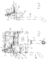
- figure 1 one recognizes an essentially conventional concealed built-in cistern 1, the interior of which opens into a flushing water pipe 2 with an underside bend 3 for connection to the flushing water connection of a toilet.
- the cistern 1 In its upper central front wall area, the cistern 1 has an inspection opening 4, to which figure 1 left and left below is an area in which the front wall is omitted only for illustration and drawing, but for example in Figure 3b can be seen in full.
- the water pipe sections 5 and 6 each contain a shut-off valve 7 and 8 in the form of a ball valve, the cold water pipe section 6 including a forward-facing filling valve connection 9. This is used in a manner known per se to connect a filling valve that can be actuated by the cistern mechanism.
- the two line sections 5 and 6 each have a flow sensor 10 or 11 and below them a bistable solenoid valve 12 or 13.
- the solenoid valves 12 and 13 can be controlled via electrical control lines by a controller not shown here.
- the control lines with the reference numerals 14 and 15 are only drawn straight further to the right.
- the controller can, for example, in figure 1 to the left of the flow sensors 10 and 11 and the solenoid valves 12 and 13, but inside the cistern 1, in the remaining cavity, for which purpose they are encapsulated to protect them from water, can be connected to an electrical supply and, in addition to the control lines 14 and 15, also have signal lines (not shown) of the flow sensors is connected or connectable.
- control could also be arranged in or in front of the inspection opening 4, for example as part of an actuating panel 5.
- the line sections 5 and 6 together with the respective flow sensor 10 or 11 and solenoid valve 12 or 13 are each a prefabricated integrated construction module.
- the two modules can also be preassembled with the controller before they are preassembled or installed in the cistern.
- a clearly visible free fall section as a system separating device, which is prescribed at least in Europe for reasons of drinking water protection.
- the water falls into a cup 16 of an immersion siphon 17.
- any form of odor trap can be used here, for example a duckbill siphon, a membrane seal or a pipe elbow siphon. It is important that the odor trap within the cup 16 is a separate odor trap 17 for the hygiene flushing device and is independent of that of the toilet.
- the cistern also serves as an overflow for the cup 16.
- a splash guard or the like can be provided around the free fall distance between the solenoid valves 12 and 13 and the cup 16, but this is not absolutely necessary and is not shown in the present case for the sake of clarity.
- a splash guard or the like can be provided around the free fall distance between the solenoid valves 12 and 13 and the cup 16, but this is not absolutely necessary and is not shown in the present case for the sake of clarity.
- the water collected in the cup 16 is then discharged further to the left via the odor trap, ie it runs off into the downpipe 18 drawn on the left outside the cistern.
- This downpipe 18 is connected to the sewage system, as will be explained with reference to the second embodiment.
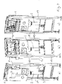
- FIGs 3a to c is the hygiene flushing device from the Figures 1 and 2 combined with a mounting frame 19 of conventional design, in which case one can speak overall of a hygienic flushing device according to the invention (with cistern and mounting frame).
- the parts of the hygiene flushing device, such as the Figures 1 and 2 show, first mounted on the cistern, namely its upper and left lateral edge, and only indirectly via the attachment of the cistern to the mounting frame on the latter. In principle, however, one could also imagine this the other way around.
- the aforementioned sewage downpipe 18 runs behind a vertical strut of the mounting frame 19 down, wherein in the Figures 3a to c the connection to the sewage line is no longer shown. All that can be seen is how the lower sheet 3 of the flushing water pipe 2 is held in a transverse support plate 20 of the mounting frame, as is known per se and is conventional.
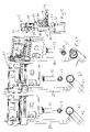
- the second exemplary embodiment shows a variant in which the odor trap, now designated 21, is arranged outside the cistern.
- the two solenoid valves thus form hygiene flushing valves and are each arranged with a flow sensor in a pipe section.
- they are therefore designed to be integrated, ie they form a uniform component which is connected to the above-mentioned fittings on the top and which is to be arranged over the cup 16 .
- the controller which is not shown, can also be attached to this component, as already mentioned.
- both the cold water line and the hot water line are covered by the hygiene flushing device and water stagnation in both line systems is counteracted in this respect.
- the hygiene flushing device there is little qualitative change in the exemplary embodiment if only one of the two lines is covered by the hygienic flushing device.
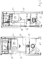
- the Figures 4a to c and 6 show that the flushing cistern 21 is narrower in its lower and central area, with the left edge, as it were, missing approximately the area occupied by the cup 16 in the first embodiment (and the area below).
- you can see an odor trap 37 which figure 5 below and in Figure 4b and c is drawn in without an outer enveloping sleeve of the downpipe 38 .
- a part of the cistern 21 is connected to an upper flange of the aforementioned dip tube of the odor trap 37 and the enveloping sleeve of the downpipe 38 under the respective outlets of the solenoid valves 34 and 35 so that they can drain into the odor trap 37. Accordingly, the water released during hygiene flushing then runs down through the downpipe 38 outside the cistern 21 .
- the upper left part of the cistern 1 forms a kind of housing for the hygiene flushing device (apart from the mounting frame and the cistern itself), this housing being integrated with the rest of the cistern.
- the second exemplary embodiment also shows how the downpipe 38 is connected at the bottom via an inclined piece to a waste water connection elbow 42 of a waste water pipe, to which the odor trap of the toilet to be connected is also to be connected (but not shown).
- This manifold 42 is held in the mounting frame 39 in a manner that is also known per se. The water from the odor trap 37 and the waste water from the toilet are therefore brought together again downstream of the odor traps and connected to the same waste water system.
- the invention thus offers good accessibility to essential components of the hygiene flushing device.
- the odor trap 37 can also be reached through the inspection opening for cleaning purposes.
- the toilet is not affected by hygiene flushing processes, which is advantageous in the manner already explained with regard to noise, limescale deposits and other possible soiling.
Landscapes
- Health & Medical Sciences (AREA)
- Life Sciences & Earth Sciences (AREA)
- Engineering & Computer Science (AREA)
- Hydrology & Water Resources (AREA)
- Public Health (AREA)
- Water Supply & Treatment (AREA)
- Sanitary Device For Flush Toilet (AREA)
Priority Applications (1)
| Application Number | Priority Date | Filing Date | Title |
|---|---|---|---|
| EP21179468.0A EP4105393B1 (fr) | 2021-06-15 | 2021-06-15 | Dispositif de rinçage d'hygiène |
Applications Claiming Priority (1)
| Application Number | Priority Date | Filing Date | Title |
|---|---|---|---|
| EP21179468.0A EP4105393B1 (fr) | 2021-06-15 | 2021-06-15 | Dispositif de rinçage d'hygiène |
Publications (2)
| Publication Number | Publication Date |
|---|---|
| EP4105393A1 true EP4105393A1 (fr) | 2022-12-21 |
| EP4105393B1 EP4105393B1 (fr) | 2025-03-19 |
Family
ID=76483079
Family Applications (1)
| Application Number | Title | Priority Date | Filing Date |
|---|---|---|---|
| EP21179468.0A Active EP4105393B1 (fr) | 2021-06-15 | 2021-06-15 | Dispositif de rinçage d'hygiène |
Country Status (1)
| Country | Link |
|---|---|
| EP (1) | EP4105393B1 (fr) |
Citations (5)
| Publication number | Priority date | Publication date | Assignee | Title |
|---|---|---|---|---|
| EP1964983A1 (fr) * | 2007-03-01 | 2008-09-03 | Geberit Technik Ag | Dispositif destiné au lavage automatique de conduites d'eau |
| DE202012102881U1 (de) * | 2012-07-31 | 2012-11-23 | Wolfgang Behm | Hygienespülvorrichtung |
| WO2018145878A1 (fr) | 2017-02-08 | 2018-08-16 | Viega Technology Gmbh & Co. Kg | Chasse d'eau pour un équipement sanitaire ainsi que chasse d'eau pour toilettes ou urinoir |
| DE202017007225U1 (de) * | 2017-03-27 | 2020-02-13 | Tece Gmbh | Hygienestation |
| DE202021102529U1 (de) * | 2021-05-10 | 2021-06-09 | Gebr. Kemper Gmbh + Co. Kg | Toilettenspülmodul und Toilette |
-
2021
- 2021-06-15 EP EP21179468.0A patent/EP4105393B1/fr active Active
Patent Citations (5)
| Publication number | Priority date | Publication date | Assignee | Title |
|---|---|---|---|---|
| EP1964983A1 (fr) * | 2007-03-01 | 2008-09-03 | Geberit Technik Ag | Dispositif destiné au lavage automatique de conduites d'eau |
| DE202012102881U1 (de) * | 2012-07-31 | 2012-11-23 | Wolfgang Behm | Hygienespülvorrichtung |
| WO2018145878A1 (fr) | 2017-02-08 | 2018-08-16 | Viega Technology Gmbh & Co. Kg | Chasse d'eau pour un équipement sanitaire ainsi que chasse d'eau pour toilettes ou urinoir |
| DE202017007225U1 (de) * | 2017-03-27 | 2020-02-13 | Tece Gmbh | Hygienestation |
| DE202021102529U1 (de) * | 2021-05-10 | 2021-06-09 | Gebr. Kemper Gmbh + Co. Kg | Toilettenspülmodul und Toilette |
Also Published As
| Publication number | Publication date |
|---|---|
| EP4105393B1 (fr) | 2025-03-19 |
Similar Documents
| Publication | Publication Date | Title |
|---|---|---|
| EP2067901A1 (fr) | Installation dotée d'un dispositif de lavage et d'une cuvette de W.-C., kit de montage destiné au montage d'une telle installation et procédé de montage d'une telle installation | |
| EP3580394B1 (fr) | Chasse d'eau pour un équipement sanitaire ainsi que chasse d'eau pour toilettes ou urinoir | |
| EP3705635B1 (fr) | Réservoir de chasse d'eau, en particulier réservoir de chasse d'eau encastré, pour des toilettes ou un urinoir, ainsi que système de conduite d'eau potable doté d'un réservoir de chasse d'eau | |
| DE69409792T2 (de) | Geruchverschlussbildende vorrichtung und spülklosettbecken versehen mit einer derartigen vorrichtung | |
| EP4089240A2 (fr) | Module de chasse d'eau de toilettes et toilettes | |
| EP4105393B1 (fr) | Dispositif de rinçage d'hygiène | |
| EP1382758A2 (fr) | Urinoir | |
| DE202021103206U1 (de) | Hygienespülvorrichtung | |
| EP4036326B1 (fr) | Système sanitaire et procédés de fabrication et d'utilisation de celui-ci | |
| EP1780343B1 (fr) | Chasse d'eau avec un dispositif pour fournir un détergent et/ou un parfum | |
| DE102018133514A1 (de) | WC-Anschlussvorrichtung zum wandseitigen Anschluss eines Dusch-WC und Verfahren zur Installation eines Dusch-WC unter Verwendung einer WC-Anschlussvorrichtung | |
| DE202017007225U1 (de) | Hygienestation | |
| WO2022029106A1 (fr) | Citerne pour un dispositif sanitaire | |
| EP4056767B1 (fr) | Station de rinçage | |
| WO1998055706A1 (fr) | Systeme de toilettes a aspiration par le vide | |
| DE19716168C2 (de) | Anlage und Verfahren zur Abwassernutzung | |
| EP1075572B1 (fr) | Cuvette de w.-c. | |
| EP0757135A1 (fr) | Réservoir de chasse d'eau | |
| EP4187028B1 (fr) | Dispositif de filtration pour un réservoir de chasse d'eau et réservoir de chasse d'eau pour un dispositif sanitaire | |
| EP1255896A1 (fr) | Kit d'une installation d'angle a paroi avant d'un w.c. ou equivalent | |
| EP4060135B1 (fr) | Chasse d'eau encastrée de construction basse | |
| DE102017106557A1 (de) | Hygienestation | |
| EP4317623A1 (fr) | Dispositif de chasse sous pression d'un cuvette de wc, cuvette de wc dotée d'un tel dispositif et son utilisation | |
| WO2023052419A1 (fr) | Dispositif de filtration pour un réservoir de chasse d'eau et réservoir de chasse d'eau pour un équipement sanitaire | |
| AT1671U1 (de) | Vorrichtung zu einem spülkasten |
Legal Events
| Date | Code | Title | Description |
|---|---|---|---|
| PUAI | Public reference made under article 153(3) epc to a published international application that has entered the european phase |
Free format text: ORIGINAL CODE: 0009012 |
|
| STAA | Information on the status of an ep patent application or granted ep patent |
Free format text: STATUS: THE APPLICATION HAS BEEN PUBLISHED |
|
| AK | Designated contracting states |
Kind code of ref document: A1 Designated state(s): AL AT BE BG CH CY CZ DE DK EE ES FI FR GB GR HR HU IE IS IT LI LT LU LV MC MK MT NL NO PL PT RO RS SE SI SK SM TR |
|
| STAA | Information on the status of an ep patent application or granted ep patent |
Free format text: STATUS: REQUEST FOR EXAMINATION WAS MADE |
|
| 17P | Request for examination filed |
Effective date: 20230619 |
|
| RBV | Designated contracting states (corrected) |
Designated state(s): AL AT BE BG CH CY CZ DE DK EE ES FI FR GB GR HR HU IE IS IT LI LT LU LV MC MK MT NL NO PL PT RO RS SE SI SK SM TR |
|
| GRAP | Despatch of communication of intention to grant a patent |
Free format text: ORIGINAL CODE: EPIDOSNIGR1 |
|
| STAA | Information on the status of an ep patent application or granted ep patent |
Free format text: STATUS: GRANT OF PATENT IS INTENDED |
|
| RIC1 | Information provided on ipc code assigned before grant |
Ipc: E03D 11/18 20060101ALI20240926BHEP Ipc: E03D 11/14 20060101ALI20240926BHEP Ipc: E03D 11/00 20060101ALI20240926BHEP Ipc: E03D 1/012 20060101ALI20240926BHEP Ipc: E03B 7/08 20060101AFI20240926BHEP |
|
| INTG | Intention to grant announced |
Effective date: 20241008 |
|
| GRAS | Grant fee paid |
Free format text: ORIGINAL CODE: EPIDOSNIGR3 |
|
| GRAA | (expected) grant |
Free format text: ORIGINAL CODE: 0009210 |
|
| STAA | Information on the status of an ep patent application or granted ep patent |
Free format text: STATUS: THE PATENT HAS BEEN GRANTED |
|
| AK | Designated contracting states |
Kind code of ref document: B1 Designated state(s): AL AT BE BG CH CY CZ DE DK EE ES FI FR GB GR HR HU IE IS IT LI LT LU LV MC MK MT NL NO PL PT RO RS SE SI SK SM TR |
|
| REG | Reference to a national code |
Ref country code: GB Ref legal event code: FG4D Free format text: NOT ENGLISH |
|
| REG | Reference to a national code |
Ref country code: CH Ref legal event code: EP |
|
| P01 | Opt-out of the competence of the unified patent court (upc) registered |
Free format text: CASE NUMBER: APP_10029/2025 Effective date: 20250227 |
|
| REG | Reference to a national code |
Ref country code: IE Ref legal event code: FG4D Free format text: LANGUAGE OF EP DOCUMENT: GERMAN |
|
| REG | Reference to a national code |
Ref country code: DE Ref legal event code: R096 Ref document number: 502021006956 Country of ref document: DE |
|
| PG25 | Lapsed in a contracting state [announced via postgrant information from national office to epo] |
Ref country code: RS Free format text: LAPSE BECAUSE OF FAILURE TO SUBMIT A TRANSLATION OF THE DESCRIPTION OR TO PAY THE FEE WITHIN THE PRESCRIBED TIME-LIMIT Effective date: 20250619 |
|
| PG25 | Lapsed in a contracting state [announced via postgrant information from national office to epo] |
Ref country code: FI Free format text: LAPSE BECAUSE OF FAILURE TO SUBMIT A TRANSLATION OF THE DESCRIPTION OR TO PAY THE FEE WITHIN THE PRESCRIBED TIME-LIMIT Effective date: 20250319 |
|
| PGFP | Annual fee paid to national office [announced via postgrant information from national office to epo] |
Ref country code: DE Payment date: 20250618 Year of fee payment: 5 |
|
| REG | Reference to a national code |
Ref country code: LT Ref legal event code: MG9D |
|
| PG25 | Lapsed in a contracting state [announced via postgrant information from national office to epo] |
Ref country code: NO Free format text: LAPSE BECAUSE OF FAILURE TO SUBMIT A TRANSLATION OF THE DESCRIPTION OR TO PAY THE FEE WITHIN THE PRESCRIBED TIME-LIMIT Effective date: 20250619 |
|
| PG25 | Lapsed in a contracting state [announced via postgrant information from national office to epo] |
Ref country code: HR Free format text: LAPSE BECAUSE OF FAILURE TO SUBMIT A TRANSLATION OF THE DESCRIPTION OR TO PAY THE FEE WITHIN THE PRESCRIBED TIME-LIMIT Effective date: 20250319 |
|
| PG25 | Lapsed in a contracting state [announced via postgrant information from national office to epo] |
Ref country code: LV Free format text: LAPSE BECAUSE OF FAILURE TO SUBMIT A TRANSLATION OF THE DESCRIPTION OR TO PAY THE FEE WITHIN THE PRESCRIBED TIME-LIMIT Effective date: 20250319 |
|
| PG25 | Lapsed in a contracting state [announced via postgrant information from national office to epo] |
Ref country code: GR Free format text: LAPSE BECAUSE OF FAILURE TO SUBMIT A TRANSLATION OF THE DESCRIPTION OR TO PAY THE FEE WITHIN THE PRESCRIBED TIME-LIMIT Effective date: 20250620 Ref country code: BG Free format text: LAPSE BECAUSE OF FAILURE TO SUBMIT A TRANSLATION OF THE DESCRIPTION OR TO PAY THE FEE WITHIN THE PRESCRIBED TIME-LIMIT Effective date: 20250319 |
|
| PGFP | Annual fee paid to national office [announced via postgrant information from national office to epo] |
Ref country code: AT Payment date: 20250721 Year of fee payment: 5 |
|
| REG | Reference to a national code |
Ref country code: NL Ref legal event code: MP Effective date: 20250319 |
|
| PG25 | Lapsed in a contracting state [announced via postgrant information from national office to epo] |
Ref country code: NL Free format text: LAPSE BECAUSE OF FAILURE TO SUBMIT A TRANSLATION OF THE DESCRIPTION OR TO PAY THE FEE WITHIN THE PRESCRIBED TIME-LIMIT Effective date: 20250319 |
|
| PG25 | Lapsed in a contracting state [announced via postgrant information from national office to epo] |
Ref country code: SE Free format text: LAPSE BECAUSE OF FAILURE TO SUBMIT A TRANSLATION OF THE DESCRIPTION OR TO PAY THE FEE WITHIN THE PRESCRIBED TIME-LIMIT Effective date: 20250319 |
|
| PG25 | Lapsed in a contracting state [announced via postgrant information from national office to epo] |
Ref country code: SM Free format text: LAPSE BECAUSE OF FAILURE TO SUBMIT A TRANSLATION OF THE DESCRIPTION OR TO PAY THE FEE WITHIN THE PRESCRIBED TIME-LIMIT Effective date: 20250319 |
|
| PG25 | Lapsed in a contracting state [announced via postgrant information from national office to epo] |
Ref country code: ES Free format text: LAPSE BECAUSE OF FAILURE TO SUBMIT A TRANSLATION OF THE DESCRIPTION OR TO PAY THE FEE WITHIN THE PRESCRIBED TIME-LIMIT Effective date: 20250319 Ref country code: PT Free format text: LAPSE BECAUSE OF FAILURE TO SUBMIT A TRANSLATION OF THE DESCRIPTION OR TO PAY THE FEE WITHIN THE PRESCRIBED TIME-LIMIT Effective date: 20250721 |
|
| PG25 | Lapsed in a contracting state [announced via postgrant information from national office to epo] |
Ref country code: IT Free format text: LAPSE BECAUSE OF FAILURE TO SUBMIT A TRANSLATION OF THE DESCRIPTION OR TO PAY THE FEE WITHIN THE PRESCRIBED TIME-LIMIT Effective date: 20250319 Ref country code: PL Free format text: LAPSE BECAUSE OF FAILURE TO SUBMIT A TRANSLATION OF THE DESCRIPTION OR TO PAY THE FEE WITHIN THE PRESCRIBED TIME-LIMIT Effective date: 20250319 |
|
| PGFP | Annual fee paid to national office [announced via postgrant information from national office to epo] |
Ref country code: CH Payment date: 20250701 Year of fee payment: 5 |
|
| PG25 | Lapsed in a contracting state [announced via postgrant information from national office to epo] |
Ref country code: CZ Free format text: LAPSE BECAUSE OF FAILURE TO SUBMIT A TRANSLATION OF THE DESCRIPTION OR TO PAY THE FEE WITHIN THE PRESCRIBED TIME-LIMIT Effective date: 20250319 Ref country code: EE Free format text: LAPSE BECAUSE OF FAILURE TO SUBMIT A TRANSLATION OF THE DESCRIPTION OR TO PAY THE FEE WITHIN THE PRESCRIBED TIME-LIMIT Effective date: 20250319 |
|
| PG25 | Lapsed in a contracting state [announced via postgrant information from national office to epo] |
Ref country code: RO Free format text: LAPSE BECAUSE OF FAILURE TO SUBMIT A TRANSLATION OF THE DESCRIPTION OR TO PAY THE FEE WITHIN THE PRESCRIBED TIME-LIMIT Effective date: 20250319 |
|
| PG25 | Lapsed in a contracting state [announced via postgrant information from national office to epo] |
Ref country code: SK Free format text: LAPSE BECAUSE OF FAILURE TO SUBMIT A TRANSLATION OF THE DESCRIPTION OR TO PAY THE FEE WITHIN THE PRESCRIBED TIME-LIMIT Effective date: 20250319 |
|
| PG25 | Lapsed in a contracting state [announced via postgrant information from national office to epo] |
Ref country code: IS Free format text: LAPSE BECAUSE OF FAILURE TO SUBMIT A TRANSLATION OF THE DESCRIPTION OR TO PAY THE FEE WITHIN THE PRESCRIBED TIME-LIMIT Effective date: 20250719 |
|
| REG | Reference to a national code |
Ref country code: DE Ref legal event code: R097 Ref document number: 502021006956 Country of ref document: DE |
|
| PG25 | Lapsed in a contracting state [announced via postgrant information from national office to epo] |
Ref country code: DK Free format text: LAPSE BECAUSE OF FAILURE TO SUBMIT A TRANSLATION OF THE DESCRIPTION OR TO PAY THE FEE WITHIN THE PRESCRIBED TIME-LIMIT Effective date: 20250319 |
|
| PLBE | No opposition filed within time limit |
Free format text: ORIGINAL CODE: 0009261 |
|
| STAA | Information on the status of an ep patent application or granted ep patent |
Free format text: STATUS: NO OPPOSITION FILED WITHIN TIME LIMIT |
|
| REG | Reference to a national code |
Ref country code: CH Ref legal event code: L10 Free format text: ST27 STATUS EVENT CODE: U-0-0-L10-L00 (AS PROVIDED BY THE NATIONAL OFFICE) Effective date: 20260128 |
|
| PG25 | Lapsed in a contracting state [announced via postgrant information from national office to epo] |
Ref country code: MC Free format text: LAPSE BECAUSE OF FAILURE TO SUBMIT A TRANSLATION OF THE DESCRIPTION OR TO PAY THE FEE WITHIN THE PRESCRIBED TIME-LIMIT Effective date: 20250319 |
|
| PG25 | Lapsed in a contracting state [announced via postgrant information from national office to epo] |
Ref country code: LU Free format text: LAPSE BECAUSE OF NON-PAYMENT OF DUE FEES Effective date: 20250615 |
|
| 26N | No opposition filed |
Effective date: 20251222 |
|
| GBPC | Gb: european patent ceased through non-payment of renewal fee |
Effective date: 20250619 |
|
| REG | Reference to a national code |
Ref country code: BE Ref legal event code: MM Effective date: 20250630 |
|
| PG25 | Lapsed in a contracting state [announced via postgrant information from national office to epo] |
Ref country code: GB Free format text: LAPSE BECAUSE OF NON-PAYMENT OF DUE FEES Effective date: 20250619 |
|
| PG25 | Lapsed in a contracting state [announced via postgrant information from national office to epo] |
Ref country code: IE Free format text: LAPSE BECAUSE OF NON-PAYMENT OF DUE FEES Effective date: 20250615 |
|
| PG25 | Lapsed in a contracting state [announced via postgrant information from national office to epo] |
Ref country code: BE Free format text: LAPSE BECAUSE OF NON-PAYMENT OF DUE FEES Effective date: 20250630 |
|
| PG25 | Lapsed in a contracting state [announced via postgrant information from national office to epo] |
Ref country code: FR Free format text: LAPSE BECAUSE OF NON-PAYMENT OF DUE FEES Effective date: 20250630 |