EP4119486A1 - Embrayage doté d'un indicateur anti-sabotage - Google Patents
Embrayage doté d'un indicateur anti-sabotage Download PDFInfo
- Publication number
- EP4119486A1 EP4119486A1 EP22184168.7A EP22184168A EP4119486A1 EP 4119486 A1 EP4119486 A1 EP 4119486A1 EP 22184168 A EP22184168 A EP 22184168A EP 4119486 A1 EP4119486 A1 EP 4119486A1
- Authority
- EP
- European Patent Office
- Prior art keywords
- clutch
- coupler
- relative
- pin
- toroidal
- Prior art date
- Legal status (The legal status is an assumption and is not a legal conclusion. Google has not performed a legal analysis and makes no representation as to the accuracy of the status listed.)
- Pending
Links
Images



Classifications
-
- B—PERFORMING OPERATIONS; TRANSPORTING
- B66—HOISTING; LIFTING; HAULING
- B66C—CRANES; LOAD-ENGAGING ELEMENTS OR DEVICES FOR CRANES, CAPSTANS, WINCHES, OR TACKLES
- B66C1/00—Load-engaging elements or devices attached to lifting or lowering gear of cranes or adapted for connection therewith for transmitting lifting forces to articles or groups of articles
- B66C1/10—Load-engaging elements or devices attached to lifting or lowering gear of cranes or adapted for connection therewith for transmitting lifting forces to articles or groups of articles by mechanical means
- B66C1/42—Gripping members engaging only the external or internal surfaces of the articles
- B66C1/44—Gripping members engaging only the external or internal surfaces of the articles and applying frictional forces
- B66C1/48—Gripping members engaging only the external or internal surfaces of the articles and applying frictional forces to vertical edge portions of sheets, tubes, or like thin or thin-walled articles
-
- B—PERFORMING OPERATIONS; TRANSPORTING
- B66—HOISTING; LIFTING; HAULING
- B66C—CRANES; LOAD-ENGAGING ELEMENTS OR DEVICES FOR CRANES, CAPSTANS, WINCHES, OR TACKLES
- B66C1/00—Load-engaging elements or devices attached to lifting or lowering gear of cranes or adapted for connection therewith for transmitting lifting forces to articles or groups of articles
- B66C1/10—Load-engaging elements or devices attached to lifting or lowering gear of cranes or adapted for connection therewith for transmitting lifting forces to articles or groups of articles by mechanical means
- B66C1/62—Load-engaging elements or devices attached to lifting or lowering gear of cranes or adapted for connection therewith for transmitting lifting forces to articles or groups of articles by mechanical means comprising article-engaging members of a shape complementary to that of the articles to be handled
- B66C1/66—Load-engaging elements or devices attached to lifting or lowering gear of cranes or adapted for connection therewith for transmitting lifting forces to articles or groups of articles by mechanical means comprising article-engaging members of a shape complementary to that of the articles to be handled for engaging holes, recesses, or abutments on articles specially provided for facilitating handling thereof
- B66C1/666—Load-engaging elements or devices attached to lifting or lowering gear of cranes or adapted for connection therewith for transmitting lifting forces to articles or groups of articles by mechanical means comprising article-engaging members of a shape complementary to that of the articles to be handled for engaging holes, recesses, or abutments on articles specially provided for facilitating handling thereof for connection to anchor inserts embedded in concrete structures
-
- B—PERFORMING OPERATIONS; TRANSPORTING
- B66—HOISTING; LIFTING; HAULING
- B66C—CRANES; LOAD-ENGAGING ELEMENTS OR DEVICES FOR CRANES, CAPSTANS, WINCHES, OR TACKLES
- B66C1/00—Load-engaging elements or devices attached to lifting or lowering gear of cranes or adapted for connection therewith for transmitting lifting forces to articles or groups of articles
- B66C1/10—Load-engaging elements or devices attached to lifting or lowering gear of cranes or adapted for connection therewith for transmitting lifting forces to articles or groups of articles by mechanical means
- B66C1/62—Load-engaging elements or devices attached to lifting or lowering gear of cranes or adapted for connection therewith for transmitting lifting forces to articles or groups of articles by mechanical means comprising article-engaging members of a shape complementary to that of the articles to be handled
-
- B—PERFORMING OPERATIONS; TRANSPORTING
- B66—HOISTING; LIFTING; HAULING
- B66C—CRANES; LOAD-ENGAGING ELEMENTS OR DEVICES FOR CRANES, CAPSTANS, WINCHES, OR TACKLES
- B66C13/00—Other constructional features or details
- B66C13/04—Auxiliary devices for controlling movements of suspended loads, or preventing cable slack
- B66C13/06—Auxiliary devices for controlling movements of suspended loads, or preventing cable slack for minimising or preventing longitudinal or transverse swinging of loads
-
- B—PERFORMING OPERATIONS; TRANSPORTING
- B66—HOISTING; LIFTING; HAULING
- B66C—CRANES; LOAD-ENGAGING ELEMENTS OR DEVICES FOR CRANES, CAPSTANS, WINCHES, OR TACKLES
- B66C13/00—Other constructional features or details
- B66C13/04—Auxiliary devices for controlling movements of suspended loads, or preventing cable slack
- B66C13/08—Auxiliary devices for controlling movements of suspended loads, or preventing cable slack for depositing loads in desired attitudes or positions
-
- B—PERFORMING OPERATIONS; TRANSPORTING
- B66—HOISTING; LIFTING; HAULING
- B66C—CRANES; LOAD-ENGAGING ELEMENTS OR DEVICES FOR CRANES, CAPSTANS, WINCHES, OR TACKLES
- B66C13/00—Other constructional features or details
- B66C13/16—Applications of indicating, registering, or weighing devices
-
- F—MECHANICAL ENGINEERING; LIGHTING; HEATING; WEAPONS; BLASTING
- F16—ENGINEERING ELEMENTS AND UNITS; GENERAL MEASURES FOR PRODUCING AND MAINTAINING EFFECTIVE FUNCTIONING OF MACHINES OR INSTALLATIONS; THERMAL INSULATION IN GENERAL
- F16B—DEVICES FOR FASTENING OR SECURING CONSTRUCTIONAL ELEMENTS OR MACHINE PARTS TOGETHER, e.g. NAILS, BOLTS, CIRCLIPS, CLAMPS, CLIPS OR WEDGES; JOINTS OR JOINTING
- F16B45/00—Hooks; Eyes
- F16B45/002—Eyes
-
- F—MECHANICAL ENGINEERING; LIGHTING; HEATING; WEAPONS; BLASTING
- F16—ENGINEERING ELEMENTS AND UNITS; GENERAL MEASURES FOR PRODUCING AND MAINTAINING EFFECTIVE FUNCTIONING OF MACHINES OR INSTALLATIONS; THERMAL INSULATION IN GENERAL
- F16B—DEVICES FOR FASTENING OR SECURING CONSTRUCTIONAL ELEMENTS OR MACHINE PARTS TOGETHER, e.g. NAILS, BOLTS, CIRCLIPS, CLAMPS, CLIPS OR WEDGES; JOINTS OR JOINTING
- F16B45/00—Hooks; Eyes
- F16B45/04—Hooks with sliding closing member
- F16B45/057—Hooks with sliding closing member the hook forming a loop or ring when interlocked with the closing member, i.e. the entire structure of the hook being loop shaped
-
- G—PHYSICS
- G09—EDUCATION; CRYPTOGRAPHY; DISPLAY; ADVERTISING; SEALS
- G09F—DISPLAYING; ADVERTISING; SIGNS; LABELS OR NAME-PLATES; SEALS
- G09F3/00—Labels, tag tickets, or similar identification or indication means; Seals; Postage or like stamps
- G09F3/02—Forms or constructions
- G09F3/03—Forms or constructions of security seals
- G09F3/0305—Forms or constructions of security seals characterised by the type of seal used
- G09F3/0317—Forms or constructions of security seals characterised by the type of seal used having bolt like sealing means
Definitions
- This invention relates to a clutch. More particularly, but not exclusively, the invention relates to an articulated clutch for lifting a concrete component by way of an anchor cast into the concrete component.
- a clutch for lifting a concrete component including a toroidal connector, a latch movable relative to the toroidal connector between a disengaged condition and an engaged condition, and a coupler for coupling the toroidal connector to a lifting apparatus, wherein the coupler includes a first part and a second part pivotal relative to the first part about a pin, and wherein the coupler includes a tamper evident indicator to indicate that the clutch has not been disassembled.
- the tamper evident indicator is arranged to indicate that the pin has not been removed from the coupler.
- the coupler is provided with a bush around a central portion of the pin. More preferably, the pin has a circular groove about its circumference and the tamper evident indicator includes a member in engagement with the circular groove to prevent movement of the pin along its longitudinal axis relative to the bush.
- the member is anchored to the bush.
- the member is in the form of a rivet.
- the member is in the form of a roll pin.
- a clutch for lifting a concrete component including a toroidal connector, a latch movable relative to the toroidal connector between a disengaged condition and an engaged condition, and a coupler for coupling the toroidal connector to a lifting apparatus, wherein the coupler is articulated.
- the coupler includes a first part and a second part pivotal relative to the first part, the first part forming a first loop engaged through the toroidal connector and the second part forming a second loop for receiving the lifting apparatus.
- the first loop is a different size to the second loop. More preferably, the first loop is smaller than the second loop.
- the second loop is adapted to allow direct fitment of a lifting chain while also allowing direct fitment of a lifting hook.
- the coupler includes an elongated pin about a longitudinal axis of which the second part is pivotal relative to the first part.
- the latch is in the form of a circular latch passing through an inner circular passage of the toroidal connector.
- a clutch for lifting a concrete component including a toroidal connector, a latch movable relative to the toroidal connector between a disengaged condition and an engaged condition, and a coupler for coupling the toroidal connector to a lifting apparatus, wherein the coupler includes a first part and a second part pivotal relative to the first part about a pin, the first part having a first circular arc and the second part having a second circular arc, and wherein the pin is located such that a longitudinal axis of the pin is perpendicular to a line connecting a centre of the first arc to a centre of the second arc.
- a clutch for lifting a concrete component including a toroidal connector, a latch in the form of a locking ring movable relative to the toroidal connector between a disengaged condition and an engaged condition, the locking ring having a handle extending radially outwardly from the toroidal connector, and a coupler for coupling the toroidal connector to a lifting apparatus, wherein the coupler includes a first part and a second part pivotal relative to the first part, the coupler being arranged to limit pivotal movement of the second part relative to the first part.
- the coupler is arranged to limit pivotal movement of the second part relative to the first part in one direction. More preferably, the coupler is arranged to limit pivotal movement of the second part relative to the first part such that said limit prevents a tip of the locking ring handle passing through an inner loop of the second part.
- the first part includes a shoulder arranged to bear against the second part at said limit.
- the second part may include a shoulder arranged to bear against the first part at said limit.
- the coupler is arranged to limit pivotal movement of the second part relative to the first part such that said limit prevents the second part from engaging with the locking ring handle to rotate the locking ring handle. More preferably, the coupler is arranged to limit pivotal movement of the second part relative to the first part such that said limit prevents the second part from engaging with the locking ring handle to rotate the locking ring handle from the engaged condition to the disengaged condition.
- a clutch for lifting a concrete component including a toroidal connector, a latch movable relative to the toroidal connector between a disengaged condition and an engaged condition, and a coupler for coupling the toroidal connector to a lifting apparatus, wherein the toroidal connector has a circular seat for sitting upon a circular upper surface of a head of and anchor coupled to the toroidal connector, wherein the circular seat terminates in a radial bearing surface for abutment with a castellation of the anchor.
- the circular seat has a first radial bearing surface for abutment with a first castellation of the anchor and a second, opposite, radial bearing surface for abutment with a second castellation of the anchor.
- the circular seat is circular about an arc having a centre at a central longitudinal axis of the latch. More preferably, the radial bearing surface is radial relative to a circle having a centre at the central longitudinal axis of the latch.
- a clutch for lifting a concrete component including a toroidal connector, a latch in the form of a locking ring movable relative to the toroidal connector between a disengaged condition and an engaged condition, the locking ring having a handle extending radially outwardly from the toroidal connector, and a coupler for coupling the toroidal connector to a lifting apparatus, wherein the locking ring handle is arranged to abut the coupler to limit rotational movement of the coupler relative to the toroidal connector.
- the locking ring handle is arranged to limit rotational movement of the coupler relative to the toroidal connector such that said limit prevents a tip of the locking ring handle passing through an inner loop of the coupler.
- the coupler is arranged to limit pivotal movement of the second part relative to the first part in two directions.
- the first part is connected to the second part by a pivotal coupling.
- the pivotal coupling includes a first hinge at one side of the coupler and a second hinge at an opposite side of the coupler.
- the first hinge and the second hinge are arranged to provide pivotal movement along a common axis.
- the coupler includes a bush between the first hinge and the second hinge. More preferably, the bush includes a stop for abutting against the first part or the second part to limit rotation of the second part relative to the first part. Even more preferably, the bush is arranged to rotate with the second part and the stop is adapted to abut against the first part to limit rotation of the second part relative to the first part.
- the first part is provided with a tab for abutment with the stop.
- the stop is in the form of a cutout having two stop surfaces, comprising a first stop surface for abutting one side of the tab and a second stop surface for abutting an opposite side of the tab for limiting rotation of the second part relative to the first part in two directions.
- the present invention may provide an articulated clutch for lifting a concrete component.
- the articulated clutch has a coupler including a first part and a second part pivotal relative to the first part.
- the first part forms a first loop and the second part forms a second loop.
- the two loops are dissimilar in size such that the top loop (when lifting) provided by the second loop will accept a crane or lifting hook but can still accept a suitable size chain fitted directly to the top loop.
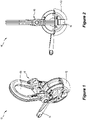
- a clutch 10 for lifting a concrete component (not shown).
- the concrete component may take several forms including, but not limited to, a concrete panel.
- the concrete component may have a cast in edge lift anchor (for example), the anchor having an eye which is used for connection to a toroidal connector of the clutch 10 for lifting the concrete panel.
- the clutch 10 includes a toroidal connector 12 and a latch 14.
- the latch 14 is movable relative to the toroidal connector 12 between a disengaged condition (in which the latch 14 is retracted into a toroidal sleeve of the toroidal connector 12) and an engaged condition (see Figure 2 ) in which the latch 14 spans a gap of the toroidal connector 12 for engagement with an eye of and anchor cast into a concrete component.
- the clutch 10 also includes a coupler 16 for coupling the toroidal connector 12 to a lifting apparatus 18, wherein the coupler 16 is articulated.
- the coupler 16 includes a first part 20 and a second part 22 pivotal relative to the first part, the first part forming a first loop 24 engaged through the toroidal connector 12 and the second part 22 forming a second loop 26 for receiving the lifting apparatus 18.
- the first loop 24 is a different size to the second loop 26. More specifically, the first loop 24 is smaller than the second loop 26.
- the second loop 26 is adapted to allow direct fitment of a lifting chain while also allowing direct fitment of a lifting hook. Accordingly, the coupler 16 allows the direct fitment of a suitable size chain like a hammerlock but also allows for direct fitment to a lifting hook as shown in Figure 5 .
- the compact size of the two loops also allows for greater head height within the factory, allowing for a gain in lifting height. This in turn allows for increased panel sizes as well as increased manoeuvrability within the factory, where lifting height is limited by the gantry height.
- the coupler 16 includes an elongated axle pin 28 about a longitudinal axis of which the second part 22 is pivotal relative to the first part 20.
- the first part 20 includes a forked end and a non-forked end. The forked end of the first part 20 engages with a non-forked end of the second part 22, whereas the non-forked end of the first part 20 engages with a forked end of the second part 22.
- the ends of the first part 20 and the second part 22 are provided with apertures through which the axle pin 28 is passed so as to hold together in pivotal relationship the first part 20 and the second part 22.
- the latch 14 is in the form of a circular latch passing through an inner circular passage of the toroidal connector 12.
- the latch 14 has a handle 30 for moving the latch 14 between the disengaged condition and the engaged condition, the handle 30 extending generally radially outwardly relative to a centre of the toroidal connector 12.
- the first part 20 has a first circular arc 32 and the second part 22 has a second circular arc 34.
- the pin 28 is located such that a longitudinal axis of the pin 28 is perpendicular to a line 36 connecting a centre 38 of the first arc 32 to a centre 40 of the second arc 34.
- axle pin 28 runs perpendicular to the centre line between the arcs of the two loops 24, 26.
- This perpendicular configuration may also assist in the articulation of the coupler 16 when it needs to be bent around the end of a concrete panel being lifted.
- the latch 14 in the form of the locking ring may have a handle 30 extending generally radially outwardly from the toroidal connector 12.
- the coupler 16 may be specifically arranged to limit pivotal movement of the second part 22 relative to the first part 20.
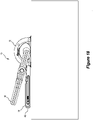
- Figure 2 the first part 20 and the second part 22 are shown in a co-planar configuration, whereas in Figures 8 to 9c there is shown a limit of pivotal movement of the second part 22 relative to the first part 20.
- the coupler 16 may be arranged to limit pivotal movement of the second part 22 relative to the first part 20 in one direction.
- the coupler 16 may also be arranged to limit pivotal movement of the second part 22 relative to the first part 20 such that the limit prevents a tip 42 of the locking ring handle passing through an inner loop 26 of the second part 22.
- the first part may include a shoulder 44 arranged to bear against the second part 22 at the limit.
- the second part 22 may include a shoulder arranged to bear against the first part 20 at the limit.
- the coupler 16 is arranged to limit pivotal movement of the second part 22 relative to the first part 20 such that the limit prevents the second part 22 from engaging with the locking ring handle 30 to rotate the locking ring handle 30.
- the coupler 16 may be arranged to limit pivotal movement of the second part 22 relative to the first part 20 such that the limit prevents the second part 22 from engaging with the locking ring handle 30 to rotate the locking ring handle 30 from the engaged condition to the disengaged condition.
- the two loops 24, 26 are limited in rotation in one direction to eliminate the large loop being able to hook under the locking ring handle 30.
- the applicant has identified that, where the upper loop (secondly 26) is large enough to accept a lifting hook, then that loop has the potential to cook under the locking ring handle 30 and could allow the clutch 10 to become disconnected from the anchor unintentionally.
- examples of the present invention are able to prevent unintentional disconnection.
- the second part 22 is pivotal relative to the first part 20 about the axle pin 28.
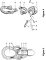
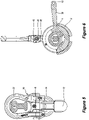
- the coupler 16 may also include a tamper evident indicator 46 to indicate that the clutch 10 has not been disassembled.
- the tamper evident indicator may be is arranged to indicate that the axle pin 28 has not been removed from the coupler 16.
- the coupler 16 is provided with a bush 48 around a central portion of the axle pin 28, the central portion being between the distal end of the first part 20 and the second part 22.
- the second part 22 may be provided with longitudinal slots which are received in corresponding longitudinal grooves of the bush 48 to keep the bush 48 aligned relative to the second part 22 and to prevent rotation of the bush 48 relative to the second part 22.
- the pin 28 may have a circular groove 50 about its circumference and the tamper evident indicator 46 may include a member in engagement with the circular groove 50 to prevent movement of the pin 28 along its longitudinal axis relative to the bush 48.
- the toroidal connector 12 may be provided with a stop pin 52 to limit rotation of the latch 14 relative to the toroidal connector 12.
- the member 46 may be anchored to the bush 48.
- the member 46 may be in the form of a rivet which passes through the bush 48 and has a flange at each end to retain the rivet relative to the bush 48.
- the member may be in the form of a roll pin.
- the bush 48 may be profiled to match the loops 24, 26, the bush 48 being secured by either a rivet or a roll pin that does not pass through the middle of the axle pin 28 but passes tangentially through the groove 50 on the axle pin 28. If secured by a rivet, the rivet will be deformed to secure it and the deformed end may have a branded logo (see Figure 5 and Figure 7 ) to indicate the handle (coupler 16) has not been tampered with. If a roll pin is used, then a seal (possibly in the form of epoxy or solder) may be used to indicate the clutch 10 has not been disassembled.
- the bush 48 has a non-cylindrical shape.
- the locking pin or rivet 46 runs tangentially through the groove 50 in the axle pin 28. Accordingly, this provides an indication to the user that the clutch 10 has not been tampered with since proof testing.
- the applicant has identified that a commercial hammerlock can be disassembled and reassembled without it being evident that this has happened. Therefore, the original proof testing and certification could be invalid as this must be conducted anytime the clutch is modified.
- the incorporation of a tamper evident feature gives the user confidence that the clutch 10 has not been tampered with since proof testing.
- the unique shape of the bush 48 allows the rivet or cross pin 46 to hold the axle 28 by the groove 50 rather than passing the centre of the axle 28. This creates far less stress concentration, making the axle 28 stronger.
- the unique shape of the bush 48 also allows the use of the tamper evident rivet 46.
- the tangentially positioned groove 50 allows for easier assembly of the system compared to that of a centrally located hole as less alignment is required (that is, alignment is only required in the x-axis and not in both x and y axes).
- the toroidal connector 12 may be provided with a circular seat 54 for sitting upon a circular upper surface 56 of a head 58 of an anchor 60 coupled to the toroidal connector 12.
- the circular seat 54 terminates in a radial bearing surface 62 for face-to-face abutment with a castellation 64 of the anchor 60.
- the circular seat 54 has a first radial bearing surface 62 for abutment with a first castellation 64 of the anchor and a second, opposite, radial bearing surface 62 for abutment with a second castellation 64 of the anchor 60.
- the circular seat 54 is circular about an arc 66 having a centre at a central longitudinal (tangential) axis 68 of the latch 14. More specifically, the radial bearing surface 62 is radial relative to a circle having a centre at the central longitudinal axis 68 of the latch 14.
- the provision of the radial bearing surfaces 62 improve the interface of the toroidal connector 12 and the anchor 60, when compared with existing connectors which abut at an edge or point.
- the applicant has identified that the face-to-face bearing provides less pressure owing to the greater surface area of contact, reducing wear on the toroidal connector 12.
- the applicant has identified that previous clutch designs for castellated anchors would see the sides of the torus bear on the castellations (or in a point or line contact where the sides of the torus meet the curved cut out).
- a new angled face interacts with the angled face of the anchor 60 to achieve a far greater bearing area resulting in less wear on the torus over time.
- the locking ring handle 30 is arranged to abut the coupler 16 to limit rotational movement of the coupler 16 relative to the toroidal connector 12.
- the locking ring handle 30 is arranged to limit rotational movement of the coupler 16 relative to the toroidal connector 12 such that the limit prevents a tip 42 of the locking ring handle 30 passing through an inner loop 26 of the coupler 16. This may be achieved by dimensioning the locking ring handle 30 such that the tip 42 of the locking ring handle 30 extends radially further from a centre of the toroidal connector 12 than an outermost edge of the coupler 16.
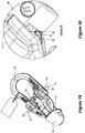
- FIG. 19 there is shown an example of the present invention in which the coupler 16 is arranged to limit pivotal movement of the second part 22 relative to the first part 20 in two directions. More specifically, as can be seen in Figure 19 , the first part 20 is connected to the second part 22 by a pivotal coupling 70.
- the pivotal coupling 70 includes a first hinge 72 at one side of the coupler 16 and a second hinge 74 at an opposite side of the coupler 16.
- the first hinge 72 and the second hinge 74 are arranged to provide pivotal movement of the second part 22 relative to the first part 21 along a common axis which may be ensured by a single axle pin 28.
- the pivotal coupling 70 includes a bush 48 between the first hinge 72 and the second hinge 74.
- the bush 48 includes a stop 76 for abutting against the first part 20 or the second part 22 to limit rotation of the second part 22 relative to the first part 20.
- the bush 48 may be arranged to rotate with the second part 22 (for example, engaged with the second part 22 by way of a tongue and groove connection) and the stop 76 may be adapted to abut against the first part 20 to limit rotation of the second part 22 relative to the first part 20.
- Figure 20 shows an enlarged and detailed view of the portion labelled "B" in Figure 19 .
- the first part 20 is provided with a tab 78 for abutment with the stop 76.
- Figure 21 shows a front view of the coupler 16
- Figure 22 shows an enlarged and detailed view of the cross-section labelled A-A in Figure 21 .
- the stop 76 may be in the form of a cutout 80 having two stop surfaces, comprising a first stop surface 82 for abutting one side of the tab 78 and a second stop surface 84 for abutting an opposite side of the tab for limiting rotation of the second part 22 relative to the first part 20 in two directions.
- this arrangement enables the limiting of angular movement of the second part 22 relative to the first part 20 in two directions and avoids a weakness which may otherwise be incurred if the limiting mechanism is attempted to be achieved within the first hinge 72 and/or the second hinge 74.
- the arrangement shown in Figures 19 to 22 takes advantage of there being no load or only little load on the coupler 16 when the rotation limiting mechanism is required to perform its duty. In other words, the arrangement shown in Figures 19 to 22 changes how rotation of the upper loop relative to the lower loop is achieved. In this revised version, this limitation of rotation is achieved between radial shoulders in the centre bush 48 that limit the movement of a lug or tab on the inside of the lower loop.
- the revised arrangement limits rotation in both directions, not just one direction. It will be understood by those skilled in the art that the two directions may be different (for example, in magnitude of limitation), thereby preventing the large loop - the second part - from interacting with the locking ring handle while allowing extra rotation in the opposite direction.
- This revised arrangement works between the lower loop - the first part 20 - and the centre bush 48, where the centre bush 48 is keyed to the upper bush to maintain alignment with the upper loop.
Landscapes
- Engineering & Computer Science (AREA)
- Mechanical Engineering (AREA)
- General Engineering & Computer Science (AREA)
- Computer Security & Cryptography (AREA)
- Physics & Mathematics (AREA)
- General Physics & Mathematics (AREA)
- Theoretical Computer Science (AREA)
- Pivots And Pivotal Connections (AREA)
- Conveying And Assembling Of Building Elements In Situ (AREA)
Applications Claiming Priority (2)
| Application Number | Priority Date | Filing Date | Title |
|---|---|---|---|
| AU2021205060A AU2021205060A1 (en) | 2021-07-14 | 2021-07-14 | Clutch having tamper evident indicator |
| AU2022204593A AU2022204593B2 (en) | 2021-07-14 | 2022-06-28 | Clutch having limited articulation |
Publications (1)
| Publication Number | Publication Date |
|---|---|
| EP4119486A1 true EP4119486A1 (fr) | 2023-01-18 |
Family
ID=82403825
Family Applications (1)
| Application Number | Title | Priority Date | Filing Date |
|---|---|---|---|
| EP22184168.7A Pending EP4119486A1 (fr) | 2021-07-14 | 2022-07-11 | Embrayage doté d'un indicateur anti-sabotage |
Country Status (3)
| Country | Link |
|---|---|
| US (1) | US12304778B2 (fr) |
| EP (1) | EP4119486A1 (fr) |
| CN (1) | CN115611142A (fr) |
Families Citing this family (1)
| Publication number | Priority date | Publication date | Assignee | Title |
|---|---|---|---|---|
| EP4119484B1 (fr) * | 2021-07-14 | 2024-09-04 | Illinois Tool Works, Inc. | Embrayage articulé |
Citations (5)
| Publication number | Priority date | Publication date | Assignee | Title |
|---|---|---|---|---|
| US4634164A (en) * | 1984-04-28 | 1987-01-06 | Siegfried Fricker | Hoisting assembly with quick-release hoisting shackle |
| US4671721A (en) * | 1984-03-12 | 1987-06-09 | Rodger Pratt | Apparatus and method for positioning an object in a building |
| US8757693B2 (en) * | 2011-09-30 | 2014-06-24 | Jergens, Inc. | Hoisting device |
| US9754469B2 (en) * | 2014-07-15 | 2017-09-05 | Savanah River Nuclear Solutions, Llc | System for tamper identification |
| CN208037866U (zh) * | 2018-02-01 | 2018-11-02 | 湖北永润建设工程有限公司 | 一种建筑设备吊装装置 |
Family Cites Families (109)
| Publication number | Priority date | Publication date | Assignee | Title |
|---|---|---|---|---|
| US474885A (en) | 1892-05-17 | Stone-lifter | ||
| DE229671C (fr) | ||||
| US821952A (en) | 1905-05-24 | 1906-05-29 | John P Murphy | Lewis-bolt. |
| US2369344A (en) * | 1941-04-21 | 1945-02-13 | Electric Steel Foundry Co | Locking device for load supporting pins |
| US2563164A (en) | 1948-07-12 | 1951-08-07 | Fletcher Co H E | Lewis |
| US2719747A (en) | 1952-04-02 | 1955-10-04 | Mark B Layne | Expansible wedge type anchor |
| US3134221A (en) | 1962-03-09 | 1964-05-26 | Jarnbirger Aktiebolag | Coupling |
| US3241309A (en) * | 1963-12-04 | 1966-03-22 | Columbus Mckinnon Corp | Connecting link |
| US3297293A (en) | 1965-01-13 | 1967-01-10 | American Drill Bushing Company | Fastening device |
| US3333388A (en) | 1965-01-13 | 1967-08-01 | Herbert J Sandin | Concrete block anchoring means for a wall plate or cap |
| US3373560A (en) * | 1966-04-18 | 1968-03-19 | Columbus Mckinnon Corp | Joiner link |
| US3404503A (en) | 1966-08-01 | 1968-10-08 | Superior Concrete Accessories | Anchor insert and releasable pick-up unit therefor |
| US3453822A (en) * | 1967-01-16 | 1969-07-08 | American Hoist & Derrick Co | Coupling link |
| US3456547A (en) | 1967-10-02 | 1969-07-22 | Gardner H Strong | Anchoring means |
| US3431012A (en) | 1967-10-23 | 1969-03-04 | Superior Concrete Accessories | Anchor insert and pickup unit for a concrete slab |
| GB1162476A (en) | 1968-02-19 | 1969-08-27 | Superior Concrete Accessories | Anchor Insert for a Concrete Slab and Pick-up Unit Therefor. |
| USRE27620E (en) * | 1971-06-28 | 1973-04-17 | Coupling link | |
| US3828550A (en) * | 1972-01-12 | 1974-08-13 | Campbell Chain Co | Coupling link |
| DE2264431C3 (de) | 1972-09-14 | 1975-06-12 | Karl 8750 Aschaffenburg Urlberger | Verankerungsvorrichtung von Geländern, Leitplanken o.dgl. in Brücken, StraBen o.dgl |
| US3846978A (en) | 1973-04-20 | 1974-11-12 | Columbus Mckinnon Corp | Joiner link pin retainer |
| US3899873A (en) * | 1974-01-07 | 1975-08-19 | Campbell Chain Co | Coupling link for chain and the like |
| US4179151A (en) | 1974-01-23 | 1979-12-18 | Superior Concrete Accessories, Inc. | Anchor insert for embedment in a concrete slab |
| US4094141A (en) * | 1974-03-12 | 1978-06-13 | August Thiele | Terminal chain link with built-in indicator |
| US4018470A (en) | 1975-06-09 | 1977-04-19 | Superior Concrete Accessories, Inc. | Anchor insert for embedment in a concrete slab |
| US4017115A (en) | 1975-12-17 | 1977-04-12 | The Burke Company | Lift system for concrete slabs |
| USRE31131E (en) | 1976-07-12 | 1983-01-25 | The Burke Company | Concrete slab hoisting apparatus |
| US4068879A (en) | 1976-07-12 | 1978-01-17 | The Burke Company | Concrete slab hoisting apparatus |
| US4107917A (en) * | 1976-09-08 | 1978-08-22 | Campbell Chain Company | Coupling link locking assembly |
| US4088361A (en) | 1976-10-06 | 1978-05-09 | A-Lok Corporation | Lifting arrangements for massive objects |
| GB1595533A (en) | 1977-02-03 | 1981-08-12 | Fricker S | Anchor for the tilt-up and transport of prefabricated building components |
| US4079983A (en) | 1977-02-04 | 1978-03-21 | W. C. Dillon And Company, Inc. | Weight lifting eye and socket |
| US4325575A (en) | 1977-03-28 | 1982-04-20 | The Burke Company | Hoisting coupling for concrete slabs |
| US4106284A (en) * | 1977-08-08 | 1978-08-15 | American Hoist & Derrick Company | Spring-biased split-sleeve coupling pin retainer |
| US4179878A (en) * | 1977-08-08 | 1979-12-25 | Baldt Incorporated | Improved coupling link |
| DE2906616A1 (de) | 1979-02-21 | 1980-08-28 | Krell | Anschlagmittel fuer zu bewegende lasten |
| US4437642A (en) * | 1980-10-23 | 1984-03-20 | The Burke Company | Lift system for tilt-up walls |
| US4367892A (en) | 1980-10-23 | 1983-01-11 | The Burke Company | Lift system for tilt-up walls |
| GB2101264A (en) * | 1981-07-01 | 1983-01-12 | Wheway Watson Holdings Limited | Pinned coupling |
| GB2139278B (en) | 1983-05-05 | 1986-07-23 | Charcon Tunnels Ltd | Connector device |
| US4512121A (en) | 1983-05-24 | 1985-04-23 | Roger Carydias | Handling system for precast units |
| US4570987A (en) | 1984-05-14 | 1986-02-18 | Hon Wong | Swivel eyebolt |
| US4525994A (en) | 1984-06-12 | 1985-07-02 | Abex Corporation | Coupling link |
| US4627198A (en) * | 1984-09-17 | 1986-12-09 | The Burke Company | Hoisting anchor assembly for use in cast concrete panels and method |
| CH668250A5 (de) | 1984-11-30 | 1988-12-15 | Deha Ankersysteme | Vorrichtung zum anhaengen eines betonfertigteils an ein hebezeug. |
| US4726561A (en) | 1986-09-15 | 1988-02-23 | Worzala Jr Edward | Concrete insert apparatus |
| US4785593A (en) | 1986-10-27 | 1988-11-22 | Munoz Jr Jose C | Structural building system |
| DE3731061A1 (de) * | 1987-09-16 | 1989-04-06 | Thiele Fa August | Verbindungsglied fuer anschlagmittel |
| WO1990010764A1 (fr) | 1989-03-07 | 1990-09-20 | Ramset Fasteners (Aust.) Pty. Limited | Ancres et griffes de levage pour dispositif de levage |
| WO1990010803A1 (fr) | 1989-03-15 | 1990-09-20 | Lars Fredriksson | Dispositif de couplage a maillon tournant |
| EP0537799A1 (fr) | 1989-05-17 | 1993-04-21 | Naka Corporation | Dispositif et structure de support pour panneaux de plancher |
| FR2651521B1 (fr) | 1989-09-05 | 1991-11-08 | Ho Dac Tinh | Crochet a bascule pour le levage de charges, tel qu'un element en beton avec anorage noye. |
| US4936612A (en) * | 1989-10-24 | 1990-06-26 | Kohn Raymond F | One-piece single engagement seal lock |
| US5261198A (en) | 1991-10-22 | 1993-11-16 | Mcmillan Larry S | Modular concrete connector |
| FR2689917A1 (fr) | 1992-04-08 | 1993-10-15 | These Ind 5 | Dispositif de sécurité pour fixation de mobilier urbain. |
| US5244243A (en) | 1992-08-24 | 1993-09-14 | Mmi Products, Inc. | Apparatus for attaching a lifting mechanism to a load |
| ES2138103T3 (es) | 1994-04-19 | 2000-01-01 | Lanchem Spa | Sistema de enganche universal para la elevacion de productos de hormigon. |
| US5732991A (en) | 1996-03-25 | 1998-03-31 | Cbc Industries, Inc. | Cast artifact handling assembly |
| AU755585B2 (en) | 1998-05-04 | 2002-12-19 | Ian Alexander Paterson | Improvements relating to the lifting of precast bodies such as concrete panels |
| AU2002320664B2 (en) | 1998-05-04 | 2004-02-12 | Ian Alexander Paterson | Improvements relating to the lifting of precast bodies such as concrete panels |
| AUPP330498A0 (en) | 1998-05-04 | 1998-05-28 | Paterson, Ian Alexander | Improvements relating to the lifting of precast bodies such as concrete panels |
| US6142546A (en) * | 1998-10-15 | 2000-11-07 | Novitec International B.V. | Ring clutch hoisting assembly |
| FR2787550B1 (fr) | 1998-12-22 | 2001-01-19 | Serac Group | Dispositif de fixation a montage-demontage rapide d'une piece mecanique en appui sur une embase de support |
| US6254300B1 (en) * | 1999-04-16 | 2001-07-03 | The Crosby Group, Inc. | Hinge pin and retention sleeve |
| JP4137531B2 (ja) | 1999-07-05 | 2008-08-20 | 株式会社日栄商事 | コンクリート製品の吊上具 |
| IT1319375B1 (it) | 2000-12-11 | 2003-10-10 | Sergio Zambelli | Inserto di sollevamento per manufatti cementizi prefabbricati constaffatura per incrementarne la resistenza a taglio |
| AUPR213600A0 (en) | 2000-12-18 | 2001-01-25 | Tiltform Design & Development Pty Ltd | Clutch assembly for tilt-up panels |
| IT1319705B1 (it) | 2000-12-21 | 2003-11-03 | Sergio Zambelli | Dispositivo di protezione di inserti di sollevamento a corpo tubolare,durante il loro inglobamento all'interno di un manufatto prefabbricato |
| EP1483466B1 (fr) | 2001-09-05 | 2008-12-24 | Austrim National Radiators Limited T/A Reid Engineering Systems | Appareil d'orientation |
| US6652012B1 (en) * | 2002-02-26 | 2003-11-25 | Jergens, Inc. | Hoist ring |
| US7065925B2 (en) | 2004-02-11 | 2006-06-27 | Universal Form Clamp Of Chicago, Inc. | Concrete anchor |
| DE202004002553U1 (de) | 2004-02-19 | 2005-03-31 | Pfeifer Holding Gmbh & Co Kg | Vorrichtung zum Anschlagen von schweren Betonfertigteilen |
| US20060248814A1 (en) | 2005-05-06 | 2006-11-09 | Yao-Chung Chen | Pedestal structure for raised access floors |
| AU2007353164B8 (en) | 2007-05-14 | 2014-05-29 | Carlos Fradera Pellicer | Cement mortar panel with prestressed biaxial reinforcement |
| PL2165029T3 (pl) * | 2007-06-21 | 2013-05-31 | Woodstock Percussion Pty Ltd | Zwalniane wieszadło |
| US7905063B2 (en) | 2008-07-15 | 2011-03-15 | Mmi Products, Inc. | Double anchor and lifting shackle for concrete slabs |
| DE102009004266A1 (de) * | 2009-01-07 | 2010-07-08 | Thiele Gmbh & Co. Kg | Kettenverbindungsglied |
| CA2788877C (fr) | 2009-02-04 | 2017-06-27 | Thomas M. Espinosa | Massif d'ancrage en beton |
| US8230931B2 (en) | 2009-12-29 | 2012-07-31 | Hydril Usa Manufacturing Llc | Lifting device and method for lifting a bonnet |
| DE102010019833B4 (de) | 2010-05-08 | 2014-02-13 | Audi Ag | Vorrichtung zum Verankern eines Anschlagmittels an einem zu transportierenden Gegenstand |
| US8381363B2 (en) * | 2010-09-27 | 2013-02-26 | The Crosby Group LLC | Securing mechanism for shackle |
| CA2988406C (fr) | 2011-03-18 | 2020-08-25 | Thomas M. Espinosa | Ensemble d'accouplement pour ancrage a beton et support de tige d'ancrage |
| US8959847B2 (en) * | 2012-06-20 | 2015-02-24 | Meadow Burke | Method and apparatus for attaching temporary lifting members to an existing lifting anchor |
| WO2014018529A1 (fr) | 2012-07-24 | 2014-01-30 | Espinosa Thomas M | Support pour ancrages de béton |
| WO2014025760A2 (fr) | 2012-08-06 | 2014-02-13 | Espinosa Thomas M | Ensembles support et ancre à béton |
| US8875471B2 (en) | 2012-08-24 | 2014-11-04 | Baltazar Siqueiros | Method and apparatus for lifting and leveling a concrete panel |
| US8708595B2 (en) | 2012-09-05 | 2014-04-29 | Hanwit Precision Industries Ltd. | Panel member locking device |
| US8966833B2 (en) | 2012-09-12 | 2015-03-03 | Mohamed R. Ally | Concrete insert |
| US8966874B2 (en) * | 2012-12-20 | 2015-03-03 | Ty-Flot, Inc. | Shackle assembly with locking pin |
| US9038360B1 (en) * | 2013-01-30 | 2015-05-26 | Ty-Flot, Inc. | Shackle assembly with locking pin |
| WO2014185911A1 (fr) | 2013-05-16 | 2014-11-20 | Illinois Tool Works Inc. | Accessoires noyés pour composants en béton et sièges de support associés |
| US9394706B2 (en) | 2013-10-08 | 2016-07-19 | Simpson Strong-Tie Company, Inc. | Concrete anchor |
| US20150167260A1 (en) | 2013-12-13 | 2015-06-18 | Baltazar Siqueiros | Method and apparatus for lifting and securing a concrete panel in place above a road bed |
| US9347232B1 (en) | 2014-03-10 | 2016-05-24 | Sidney E. Francies, III | Lifting and leveling assembly for precast concrete slabs and method |
| IN2014MU03674A (fr) | 2014-04-03 | 2015-10-09 | Hong Nam Kim | |
| US9169900B1 (en) * | 2014-06-09 | 2015-10-27 | Ty-Flot, Inc. | Shackle assembly with pin and retaining ring |
| US10724559B2 (en) * | 2014-08-29 | 2020-07-28 | Esco Group Llc | Hammerless pin assembly |
| US10767323B2 (en) | 2014-08-29 | 2020-09-08 | Illinois Tool Works Inc. | Lifting of concrete components |
| US20160230380A1 (en) | 2015-02-11 | 2016-08-11 | Black & Decker Inc. | Concrete anchor |
| EP3313769B8 (fr) | 2015-06-24 | 2023-08-16 | Woodstock Percussion Pty Ltd | Insert de levage à bord étroit |
| US10030380B2 (en) | 2015-11-20 | 2018-07-24 | ToolTech, LLC | Concrete slab anchor |
| BR112018012224B1 (pt) | 2015-12-17 | 2022-07-19 | Inventio Ag | Módulo de fixação, sistema de elevador e processo para fixação de uma sapata de trilho de um trilho de elevador |
| WO2018057577A1 (fr) * | 2016-09-21 | 2018-03-29 | Esco Corporation | Ensemble de broche |
| US11585069B2 (en) * | 2018-06-06 | 2023-02-21 | Caterpillar Inc. | Pin and retainer locking system |
| US10774523B2 (en) | 2018-02-08 | 2020-09-15 | Reubart Enterprises, LLC | Brace insert device used in the construction of concrete panels |
| US11369816B2 (en) | 2018-04-26 | 2022-06-28 | Pure Safety Group, Inc. | Positionable connector assembly |
| US10576868B1 (en) | 2018-11-07 | 2020-03-03 | Mashak Gilmour Company LLC | Cargo tie-down and a combination cargo tie-down and rail, and a method of securing the cargo tie-down to a rail |
| AU2019279923B2 (en) | 2018-12-11 | 2025-12-11 | Plastic Solutions Australia Pty Ltd | Lifting anchor |
| TWI730449B (zh) | 2019-10-15 | 2021-06-11 | 潤弘精密工程事業股份有限公司 | 吊裝裝置及使用該吊裝裝置之吊裝方法 |
| US11167957B1 (en) * | 2020-11-09 | 2021-11-09 | Suncor Stainless, Inc. | Swiveling hoist rings and methods of assembly |
-
2022
- 2022-07-11 EP EP22184168.7A patent/EP4119486A1/fr active Pending
- 2022-07-13 US US17/863,937 patent/US12304778B2/en active Active
- 2022-07-14 CN CN202210831448.2A patent/CN115611142A/zh active Pending
Patent Citations (5)
| Publication number | Priority date | Publication date | Assignee | Title |
|---|---|---|---|---|
| US4671721A (en) * | 1984-03-12 | 1987-06-09 | Rodger Pratt | Apparatus and method for positioning an object in a building |
| US4634164A (en) * | 1984-04-28 | 1987-01-06 | Siegfried Fricker | Hoisting assembly with quick-release hoisting shackle |
| US8757693B2 (en) * | 2011-09-30 | 2014-06-24 | Jergens, Inc. | Hoisting device |
| US9754469B2 (en) * | 2014-07-15 | 2017-09-05 | Savanah River Nuclear Solutions, Llc | System for tamper identification |
| CN208037866U (zh) * | 2018-02-01 | 2018-11-02 | 湖北永润建设工程有限公司 | 一种建筑设备吊装装置 |
Also Published As
| Publication number | Publication date |
|---|---|
| CN115611142A (zh) | 2023-01-17 |
| US20230021585A1 (en) | 2023-01-26 |
| US12304778B2 (en) | 2025-05-20 |
Similar Documents
| Publication | Publication Date | Title |
|---|---|---|
| CA1236143A (fr) | Appareil de levage avec poulie a degagement rapide | |
| US6729079B2 (en) | Concrete anchor | |
| EP4119487A1 (fr) | Embrayage à surfaces de butée | |
| US12304778B2 (en) | Clutch having tamper evident indicator | |
| US4940261A (en) | Pipe couplings | |
| AU2008265491B2 (en) | Releasable lifting link | |
| US4094141A (en) | Terminal chain link with built-in indicator | |
| AU2022204593B2 (en) | Clutch having limited articulation | |
| EP4119484A1 (fr) | Embrayage articulé | |
| US12630398B2 (en) | Clutch having limited articulation | |
| AU2021205059B2 (en) | Clutch having limited articulation | |
| NZ790116A (en) | Clutch having limited articulation | |
| NZ790128A (en) | Clutch having abutment surfaces | |
| AU2021205058A1 (en) | Articulated clutch | |
| AU2021205061A1 (en) | Clutch having abutment surfaces | |
| AU2021205060A1 (en) | Clutch having tamper evident indicator | |
| NZ790106A (en) | Articulated clutch | |
| NZ793753A (en) | Clutch having limited articulation | |
| JP3172534B2 (ja) | コンクリート建築要素を引上げるための負荷係合装置 | |
| JP2011219220A (ja) | 角コラム用継手の吊り上げに用いるクランプ | |
| CN207497912U (zh) | 一种用于大型单管桩翻身的吊具 | |
| JPH11208226A (ja) | タイヤチェーン用側方固定具 | |
| AU2008329539B2 (en) | Improved lifting link | |
| JP2551792Y2 (ja) | 腹起し取り付け用補助ピースのつり上げ用クランプ | |
| JP2536437Y2 (ja) | コンクリートセグメントの継手金具 |
Legal Events
| Date | Code | Title | Description |
|---|---|---|---|
| PUAI | Public reference made under article 153(3) epc to a published international application that has entered the european phase |
Free format text: ORIGINAL CODE: 0009012 |
|
| STAA | Information on the status of an ep patent application or granted ep patent |
Free format text: STATUS: THE APPLICATION HAS BEEN PUBLISHED |
|
| AK | Designated contracting states |
Kind code of ref document: A1 Designated state(s): AL AT BE BG CH CY CZ DE DK EE ES FI FR GB GR HR HU IE IS IT LI LT LU LV MC MK MT NL NO PL PT RO RS SE SI SK SM TR |
|
| STAA | Information on the status of an ep patent application or granted ep patent |
Free format text: STATUS: REQUEST FOR EXAMINATION WAS MADE |
|
| 17P | Request for examination filed |
Effective date: 20230714 |
|
| RBV | Designated contracting states (corrected) |
Designated state(s): AL AT BE BG CH CY CZ DE DK EE ES FI FR GB GR HR HU IE IS IT LI LT LU LV MC MK MT NL NO PL PT RO RS SE SI SK SM TR |
|
| GRAP | Despatch of communication of intention to grant a patent |
Free format text: ORIGINAL CODE: EPIDOSNIGR1 |
|
| STAA | Information on the status of an ep patent application or granted ep patent |
Free format text: STATUS: GRANT OF PATENT IS INTENDED |