EP4119952A1 - Automatische analysevorrichtung - Google Patents
Automatische analysevorrichtung Download PDFInfo
- Publication number
- EP4119952A1 EP4119952A1 EP21768712.8A EP21768712A EP4119952A1 EP 4119952 A1 EP4119952 A1 EP 4119952A1 EP 21768712 A EP21768712 A EP 21768712A EP 4119952 A1 EP4119952 A1 EP 4119952A1
- Authority
- EP
- European Patent Office
- Prior art keywords
- specimen
- vessel
- automatic analyzer
- dimensional code
- unit
- Prior art date
- Legal status (The legal status is an assumption and is not a legal conclusion. Google has not performed a legal analysis and makes no representation as to the accuracy of the status listed.)
- Granted
Links
Images


Classifications
-
- G—PHYSICS
- G01—MEASURING; TESTING
- G01N—INVESTIGATING OR ANALYSING MATERIALS BY DETERMINING THEIR CHEMICAL OR PHYSICAL PROPERTIES
- G01N35/00—Automatic analysis not limited to methods or materials provided for in any single one of groups G01N1/00 - G01N33/00; Handling materials therefor
- G01N35/00584—Control arrangements for automatic analysers
- G01N35/00722—Communications; Identification
- G01N35/00732—Identification of carriers, materials or components in automatic analysers
-
- G—PHYSICS
- G01—MEASURING; TESTING
- G01N—INVESTIGATING OR ANALYSING MATERIALS BY DETERMINING THEIR CHEMICAL OR PHYSICAL PROPERTIES
- G01N35/00—Automatic analysis not limited to methods or materials provided for in any single one of groups G01N1/00 - G01N33/00; Handling materials therefor
- G01N35/02—Automatic analysis not limited to methods or materials provided for in any single one of groups G01N1/00 - G01N33/00; Handling materials therefor using a plurality of sample containers moved by a conveyor system past one or more treatment or analysis stations
- G01N35/04—Details of the conveyor system
-
- G—PHYSICS
- G01—MEASURING; TESTING
- G01N—INVESTIGATING OR ANALYSING MATERIALS BY DETERMINING THEIR CHEMICAL OR PHYSICAL PROPERTIES
- G01N35/00—Automatic analysis not limited to methods or materials provided for in any single one of groups G01N1/00 - G01N33/00; Handling materials therefor
- G01N35/00584—Control arrangements for automatic analysers
- G01N35/00722—Communications; Identification
- G01N35/00732—Identification of carriers, materials or components in automatic analysers
- G01N2035/00792—Type of components bearing the codes, other than sample carriers
- G01N2035/00801—Holders for sample carriers, e.g. trays, caroussel, racks
-
- G—PHYSICS
- G01—MEASURING; TESTING
- G01N—INVESTIGATING OR ANALYSING MATERIALS BY DETERMINING THEIR CHEMICAL OR PHYSICAL PROPERTIES
- G01N35/00—Automatic analysis not limited to methods or materials provided for in any single one of groups G01N1/00 - G01N33/00; Handling materials therefor
- G01N35/02—Automatic analysis not limited to methods or materials provided for in any single one of groups G01N1/00 - G01N33/00; Handling materials therefor using a plurality of sample containers moved by a conveyor system past one or more treatment or analysis stations
- G01N35/04—Details of the conveyor system
- G01N2035/0401—Sample carriers, cuvettes or reaction vessels
- G01N2035/0412—Block or rack elements with a single row of samples
-
- G—PHYSICS
- G01—MEASURING; TESTING
- G01N—INVESTIGATING OR ANALYSING MATERIALS BY DETERMINING THEIR CHEMICAL OR PHYSICAL PROPERTIES
- G01N35/00—Automatic analysis not limited to methods or materials provided for in any single one of groups G01N1/00 - G01N33/00; Handling materials therefor
- G01N35/02—Automatic analysis not limited to methods or materials provided for in any single one of groups G01N1/00 - G01N33/00; Handling materials therefor using a plurality of sample containers moved by a conveyor system past one or more treatment or analysis stations
- G01N35/04—Details of the conveyor system
- G01N2035/0439—Rotary sample carriers, i.e. carousels
- G01N2035/0443—Rotary sample carriers, i.e. carousels for reagents
-
- G—PHYSICS
- G01—MEASURING; TESTING
- G01N—INVESTIGATING OR ANALYSING MATERIALS BY DETERMINING THEIR CHEMICAL OR PHYSICAL PROPERTIES
- G01N35/00—Automatic analysis not limited to methods or materials provided for in any single one of groups G01N1/00 - G01N33/00; Handling materials therefor
- G01N35/02—Automatic analysis not limited to methods or materials provided for in any single one of groups G01N1/00 - G01N33/00; Handling materials therefor using a plurality of sample containers moved by a conveyor system past one or more treatment or analysis stations
- G01N35/04—Details of the conveyor system
- G01N2035/0474—Details of actuating means for conveyors or pipettes
- G01N2035/0491—Position sensing, encoding; closed-loop control
Definitions
- the invention relates to an automatic analyzer.
- an automatic analyzer for analyzing a sample a sample which is put in a specimen vessel is mounted on the automatic analyzer.
- the automatic analyzer detects the mounted specimen vessel, dispenses the sample, and analyzes the component thereof, the concentration, and the like.
- Patent Literature 1 as the prior art related to the vessel detection, barcode labels are respectively attached to an inner peripheral surface and an outer peripheral surface of a supporting unit of a vessel rack.
- the Patent Literature 1 discloses a specimen analysis device in which after a barcode reader reads the barcode label on the outer peripheral surface, when the barcode label attached to the reagent vessel is read without reading the barcode label on the inner peripheral surface, the control unit determines that the vessel containing a reagent in accordance with the information read from the barcode label of the reagent vessel is supported by the supporting unit of the vessel rack.
- Patent Literature 1 Japanese Patent Laid-Open No. 2008-20335
- the automatic analyzer when a barcode label is not attached to a vessel, the automatic analyzer cannot detect the vessel and cannot perform an analysis of a sample.
- the invention aims to provide an automatic analyzer capable of detecting a specimen vessel even when a barcode label is not attached to the specimen vessel.
- the invention provides an automatic analyzer including a mounting unit for mounting a specimen vessel that stores a specimen to be analyzed, a first identifier arranged at a back position of the mounting unit, a reading unit arranged at a front position of the mounting unit and reading the first identifier, and a control unit for determining whether the specimen vessel is mounted on the mounting unit based on whether a contrast value of the like reflected from the first identifier is equal to or greater than a threshold, by using a signal read by the reading unit.
- the invention further provides an automatic analyzer including a reagent specimen disk having a mounting unit for mounting a specimen vessel that stores a specimen to be analyzed on an outer peripheral portion thereof, a two-dimensional code arranged on the reagent specimen disk at a back position of the mounting unit, a barcode arranged on a side surface of the specimen vessel, a reading unit arranged at a front position of the mounting unit and capable of reading the two-dimensional code and the barcode, and a control unit for determining whether the specimen vessel is mounted on the mounting unit based on whether a contrast value of the light reflected from the two-dimensional code is equal to or greater than a threshold set in advance, by using an output signal of the reading unit.
- the first embodiment is an automatic analyzer provided with a function of detecting the presence or absence of a specimen vessel.
- the automatic analyzer includes a mounting unit for mounting a specimen vessel that stores a specimen to be analyzed, a first identifier arranged at a back position of the mounting unit, a reading unit arranged at a front position of the mounting unit and reading the first identifier, and a control unit for determining whether the specimen vessel is mounted on the mounting unit based on whether a contrast value of the light reflected from the first identifier is equal to or greater than a threshold, by using a signal read by the reading unit.
- the automatic analyzer 1 has a reagent specimen disk 2 for mounting a reagent bottle 3 storing a reagent and a specimen vessel 4 storing a specimen and a barcode reader 5 as a reading unit for reading an identifier attached to the specimen vessel 4.
- This identifier is used to identify the specimen of the specimen vessel.
- the reagent specimen disk 2 has a transport unit 6 for delivering the specimen vessel 4 using the specimen vessel mounting rack and a reagent holding unit 7 where a plurality of the reagent bottles 3 are arranged, and the transport unit 6 can carry the specimen vessel 4 independently of the reagent holding unit 7.
- the specimen and the reagent dispensed from the reagent specimen disk 2 using dispensing arms 8 and 9 are discharged to a reaction disk 10, where reaction is performed for a required time period.
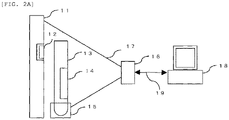
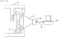
- Fig. 2A is a schematic diagram of the function of detecting the presence or absence of a specimen vessel according to this embodiment. Specifically, it shows the configuration of the automatic analyzer including a reagent specimen disk having a mounting unit for mounting a specimen vessel that stores a specimen to be analyzed on an outer peripheral portion thereof, a two-dimensional code arranged on the reagent specimen disk at a back position of the mounting unit, a barcode arranged on a side surface of the specimen vessel, a reading unit arranged at a front position of the mounting unit and capable of reading the two-dimensional code and the barcode, and a control unit for determining whether the specimen vessel is mounted on the mounting unit based on whether a contrast value of the light reflected from the two-dimensional code is equal to or greater than a threshold set in advance, by using an output signal of the reading unit.
- This automatic analyzer includes a reagent specimen disk 11 corresponding to the reagent specimen disk 2 as illustrated in Fig. 1 , a sensor 16 forming the barcode reader 5 and a sensor reading range 17, a control unit 18 for controlling the whole of the automatic analyzer, and a communication unit 19 for performing communication between the sensor 16 and the control unit 18.
- the reagent specimen disk 11 may have a top cover and a bottom and therebetween it may have the two-dimensional code 12 as the first identifier suspended from the top cover and a specimen vessel mounting rack 15 as the mounting unit for mounting the specimen vessel 13.
- the position where the two-dimensional code 12 is suspended is near the boundary between the transport unit 6 and the reagent holding unit 7 in Fig. 1 .
- the sensor 16 as the barcode reader can read the two-dimensional code 12 as the first identifier suspended from the top cover and the barcode label 14 as the second identifier attached to a side surface of the specimen vessel 13.
- the data matrix code ECC 200 is used as the two-dimensional code 12, for example.
- the control unit 18 performs the processing such as the reading information processing by running the processing program of a central processing unit (CPU) and a control of the whole system.
- CPU central processing unit
- the sensor 16 has a sensor reading range 17 for reading the barcode label 14 attached to the specimen vessel and the two-dimensional code 12 of the reagent specimen disk 11.
- the sensor 16 transmits the reading information of the barcode label 14, the reading information of the two-dimensional code 12, and further a contrast value at a time of reading the two-dimensional code 12 to the control unit 18, through the communication unit 19.
- This contrast value may be output from the sensor 16 or may be calculated from the reading information received by the control unit 18.
- Fig. 3 is a diagram showing an example of a processing flow of the automatic analyzer having the function of detecting the presence or absence of a specimen vessel according to the first embodiment.
- the subject of the processing flow is the control unit 18.
- the control unit 18 of the automatic analyzer 1 Prior to the confirming operation of the presence or absence of the specimen vessel, the control unit 18 of the automatic analyzer 1 reads the two-dimensional code 12 of the reagent specimen disk 11 by the sensor 16 with no specimen vessel mounted there and controls to acquire the contrast value of an image of the two-dimensional code 12, by using an output signal of the sensor 16 (Step 31, hereinafter referred to as S31).
- the control unit 18 calculates a threshold of the contrast value of the image of the two-dimensional code 12 (S32).
- the threshold of the contrast value is calculated by using the sensor output signal of a black portion and a white portion of the two-dimensional code.
- the contrast value of the black portion when there is no specimen vessel is 80 and when the contrast value when there is a specimen vessel is 20, the threshold may be defined as 50.
- the transport unit 6 of the reagent specimen disk 2 is moved and as illustrated in Figs. 2A and 2B , the specimen vessel mounting position on the specimen vessel mounting rack 15 is moved to in front of the two-dimensional code 12 (S33).
- the sensor 16 as the barcode reader reads the two-dimensional code 12 to acquire the contrast value (S34).
- the control unit determines that there is a specimen vessel (S38).
- the two-dimensional code can be read YES in S35
- the contrast value is lower than the threshold calculated in advance (NO in S36)
- the two-dimensional code can be read YES in S35
- the contrast value is equal to or greater than the threshold (S36)
- control unit After the above determination of the presence or absence of a specimen vessel, when the control unit does not confirm the presence or absence of a specimen vessel on all the mounting positions of the specimen vessel 13 (NO in S39), it rotates the reagent specimen disk 11 (S33) and confirms the presence or absence of a specimen vessel at the next mounting position. When confirming the above on all the mounting positions, the control unit finishes the operation of detecting the presence or absence of a specimen vessel (YES in S39).
- the function of detecting the presence or absence of a specimen vessel of the embodiment as mentioned above, it is possible to detect the presence or absence of the specimen vessel 13 by using the output signal of the sensor 16 as the barcode reader arranged to read the barcode 14 attached to the specimen vessel and thereby to reduce the cost because of saving another exclusive sensor and the like for detecting the presence or absence of a specimen vessel. It is no need to adjust the sensor and the like, hence to improve the maintenance performance.
- the second embodiment is an automatic analyzer provided with a function of detecting the presence or absence of a specimen vessel and a function of detecting a vessel type.
- a plurality of two-dimensional codes is arranged, and of the plural two-dimensional codes, based on the number of the two-dimensional codes read by the reading unit, the control unit determines each specimen vessel type.
- the automatic analyzer of the embodiment is also provided with a reagent specimen disk 2 for mounting a reagent bottle 3 storing a reagent and a specimen vessel 4 storing a specimen and a barcode reader 5 for reading a barcode attached to the specimen vessel, similarly to the first embodiment.
- a specimen vessel mounting rack 15 for mounting a reagent bottle 3 storing a reagent and a specimen vessel 4 storing a specimen and a barcode reader 5 for reading a barcode attached to the specimen vessel, similarly to the first embodiment.
- a specimen vessel mounting rack 15 as a barcode reader for reading a two-dimensional code 12 as a first identifier attached to a reagent specimen disk 11 at a predetermined position and a barcode 14 as a second identifier attached to the specimen vessel 13, a control unit 18 for controlling the automatic analyzer, and a communication unit 19 for performing communication between the sensor 16 and the control unit 18.
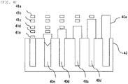
- Fig. 4 is a schematic diagram of a function of detecting the presence or absence of a specimen vessel and a function of detecting a vessel type of the automatic analyzer according to the second embodiment.
- a plurality of specimen vessels 40a to 40e of various types is mounted on a specimen vessel mounting rack 42 for mounting the specimen vessels.
- a plurality of two-dimensional codes 41a to 41e is arranged at a predetermined position of the reagent specimen disk 11.
- the predetermined position means, for example, the downwardly suspending portion of the top cover of the reagent specimen disk 2 as illustrated in Fig. 2B or an outer peripheral surface of the reagent holding unit 7.
- the vessel types of the specimen vessels 40a to 40e can be determined by the combination of the codes readable (YES in S35 of Fig. 3 ) and having the contrast value equal to or greater than a threshold (YES in S36), of the plural two-dimensional codes 41a to 41e.
- the specimen vessels 40a to 40e illustrated in Fig. 4 have various heights.
- the vessels are 100 mm tube, 75 mm tube, 50 mm tube and the like.
- the specimen vessel 40e shows a sample tube.
- the configuration of the embodiment in addition to the effect of the first embodiment, it is possible to determine the type of a specimen vessel by using the sensor 16 as the barcode reader set to read the barcode 14 attached to the specimen vessel and a sample within the specimen vessel, which makes it unnecessary to set a mechanism for exclusive use for type determination, hence to reduce the cost. Further, the maintenance performance is improved because of not requiring the adjustment of the exclusive determination mechanism.
- control unit and the like have been described mainly with the examples of creating and executing various types of processing programs for realizing one or all of the above, it is needless to say that one or all of them may be realized in hardware, for example, by designing the above in an integrated circuit.
- the whole or a part of the functions of the control unit may be realized by an integrated circuit such as, for example, ASIC (Application Specific Integrated Circuit) or FPGA (Field Programmable Gate Array), instead of the program.
- ASIC Application Specific Integrated Circuit
- FPGA Field Programmable Gate Array
Landscapes
- Physics & Mathematics (AREA)
- Health & Medical Sciences (AREA)
- Life Sciences & Earth Sciences (AREA)
- Chemical & Material Sciences (AREA)
- Analytical Chemistry (AREA)
- Biochemistry (AREA)
- General Health & Medical Sciences (AREA)
- General Physics & Mathematics (AREA)
- Immunology (AREA)
- Pathology (AREA)
- Automatic Analysis And Handling Materials Therefor (AREA)
Applications Claiming Priority (2)
| Application Number | Priority Date | Filing Date | Title |
|---|---|---|---|
| JP2020041725 | 2020-03-11 | ||
| PCT/JP2021/005818 WO2021182038A1 (ja) | 2020-03-11 | 2021-02-17 | 自動分析装置 |
Publications (3)
| Publication Number | Publication Date |
|---|---|
| EP4119952A1 true EP4119952A1 (de) | 2023-01-18 |
| EP4119952A4 EP4119952A4 (de) | 2024-03-13 |
| EP4119952B1 EP4119952B1 (de) | 2025-07-09 |
Family
ID=77672266
Family Applications (1)
| Application Number | Title | Priority Date | Filing Date |
|---|---|---|---|
| EP21768712.8A Active EP4119952B1 (de) | 2020-03-11 | 2021-02-17 | Automatische analysevorrichtung |
Country Status (5)
| Country | Link |
|---|---|
| US (1) | US20230079568A1 (de) |
| EP (1) | EP4119952B1 (de) |
| JP (1) | JP7414953B2 (de) |
| CN (1) | CN115210579A (de) |
| WO (1) | WO2021182038A1 (de) |
Families Citing this family (2)
| Publication number | Priority date | Publication date | Assignee | Title |
|---|---|---|---|---|
| US20250189550A1 (en) * | 2022-03-07 | 2025-06-12 | Hitachi High-Tech Corporation | Automatic analyzer |
| JP7649584B1 (ja) * | 2024-09-10 | 2025-03-21 | 株式会社オプトエレクトロニクス | 光学的情報読取装置及び方法 |
Family Cites Families (20)
| Publication number | Priority date | Publication date | Assignee | Title |
|---|---|---|---|---|
| JPS61275657A (ja) * | 1985-05-31 | 1986-12-05 | Hitachi Ltd | 自動分析装置の検体認識装置 |
| JPH01214764A (ja) * | 1988-02-24 | 1989-08-29 | Toshiba Corp | 自動化学分析装置 |
| US5700429A (en) * | 1995-04-19 | 1997-12-23 | Roche Diagnostic Systems, Inc. | Vessel holder for automated analyzer |
| US6329139B1 (en) * | 1995-04-25 | 2001-12-11 | Discovery Partners International | Automated sorting system for matrices with memory |
| JP3602063B2 (ja) * | 2001-03-23 | 2004-12-15 | 株式会社日立製作所 | 検出対象の寸法を自動的に検出する装置及びそれを用いた自動分析装置 |
| JP2004054645A (ja) * | 2002-07-19 | 2004-02-19 | Keyence Corp | 二次元コード読取装置、二次元コード読取方法、二次元コード読取プログラムおよびコンピュータ読取可能な記録媒体 |
| JP2006277481A (ja) * | 2005-03-30 | 2006-10-12 | Matsushita Electric Ind Co Ltd | 光学情報読取装置 |
| JP4817181B2 (ja) | 2006-07-13 | 2011-11-16 | シスメックス株式会社 | 検体分析装置および識別子読取方法 |
| JP4980671B2 (ja) * | 2006-08-18 | 2012-07-18 | シスメックス株式会社 | 血液試料分析装置 |
| JP2009031175A (ja) * | 2007-07-30 | 2009-02-12 | Hitachi High-Technologies Corp | 自動分析装置 |
| JP5183249B2 (ja) * | 2008-02-29 | 2013-04-17 | シスメックス株式会社 | 試料分析装置、及び試料分析方法 |
| US8170271B2 (en) * | 2008-06-25 | 2012-05-01 | Jadak Llc | System and method for test tube and cap identification |
| JP5280797B2 (ja) * | 2008-10-27 | 2013-09-04 | シスメックス株式会社 | 検体分析装置 |
| EP2808834B1 (de) * | 2013-05-29 | 2017-07-12 | BDT Media Automation GmbH | Verfahren und Vorrichtung zur Erkennung und Bestimmung der Anwesenheit von Objekten in Lagerstellen mithilfe eines Strichcodelesegeräts |
| JP6348816B2 (ja) * | 2014-09-30 | 2018-06-27 | 株式会社日立ハイテクノロジーズ | 自動分析装置 |
| JP2016153999A (ja) * | 2015-02-17 | 2016-08-25 | 横河電機株式会社 | 管理装置、管理システム、管理方法、管理プログラム、及び記録媒体 |
| JP2017049816A (ja) * | 2015-09-02 | 2017-03-09 | キヤノン株式会社 | 撮像装置の制御システム、制御方法、及び制御プログラム、コード読取システム、並びに生産システム |
| JP2018531391A (ja) * | 2015-10-23 | 2018-10-25 | ジェン−プローブ・インコーポレーテッド | ラック及びレセプタクル上の機械可読マークを読み取るためのシステム及び方法 |
| WO2019084468A1 (en) * | 2017-10-27 | 2019-05-02 | Beckman Coulter, Inc. | RECOGNITION OF SAMPLE CONTAINER |
| CN108985129B (zh) * | 2018-08-02 | 2021-11-23 | 谷东科技有限公司 | 二维码的定位与检出方法 |
-
2021
- 2021-02-17 EP EP21768712.8A patent/EP4119952B1/de active Active
- 2021-02-17 CN CN202180017771.XA patent/CN115210579A/zh active Pending
- 2021-02-17 JP JP2022505869A patent/JP7414953B2/ja active Active
- 2021-02-17 WO PCT/JP2021/005818 patent/WO2021182038A1/ja not_active Ceased
- 2021-02-17 US US17/802,215 patent/US20230079568A1/en active Pending
Also Published As
| Publication number | Publication date |
|---|---|
| CN115210579A (zh) | 2022-10-18 |
| JP7414953B2 (ja) | 2024-01-16 |
| WO2021182038A1 (ja) | 2021-09-16 |
| US20230079568A1 (en) | 2023-03-16 |
| EP4119952A4 (de) | 2024-03-13 |
| JPWO2021182038A1 (de) | 2021-09-16 |
| EP4119952B1 (de) | 2025-07-09 |
Similar Documents
| Publication | Publication Date | Title |
|---|---|---|
| US11630115B2 (en) | Sample testing system with automated control of sample retesting | |
| US8158058B2 (en) | Automatic analyzer | |
| EP3415920B1 (de) | Automatische analysevorrichtung | |
| EP3176587B1 (de) | Automatisierter analysator | |
| EP4119952A1 (de) | Automatische analysevorrichtung | |
| EP3789770A1 (de) | Automatische analysevorrichtung | |
| US11860177B2 (en) | Analysis method of automatic analyzer | |
| US20230258672A1 (en) | Automated Analysis Device | |
| US20130260412A1 (en) | Sample processing apparatus, sample analyzer, sample analyzing system, sample processing system and sample processing method | |
| EP2554999B1 (de) | Probenanalysevorrichtung und probenanalysesystem | |
| JP2012108010A (ja) | 自動分析装置 | |
| EP4296685A1 (de) | Automatische analysevorrichtung und verfahren zur probenabsaugung in einer automatischen analysevorrichtung | |
| EP2554998B1 (de) | Probenanalysesystem | |
| US8594836B2 (en) | Sample processing system, sample processing method, and computer program product | |
| EP4446746A1 (de) | Probenfördervorrichtung und probenförderverfahren | |
| JP7825484B2 (ja) | 自動分析装置、及び液面検出方法 | |
| CN112820390B (zh) | 一种优先程度的设置方法、测试方法和样本分析系统 | |
| JP2006292699A (ja) | 自動分析装置 | |
| EP4692803A1 (de) | Automatische analysevorrichtung | |
| US20240302396A1 (en) | Automatic analyzer | |
| JP2000241435A (ja) | 生化学自動分析装置 | |
| CN120721992A (zh) | 样本分析系统 | |
| CN120721990A (zh) | 样本分析系统及样本调度方法 | |
| CN112534269A (zh) | 自动分析装置以及自动分析系统 |
Legal Events
| Date | Code | Title | Description |
|---|---|---|---|
| STAA | Information on the status of an ep patent application or granted ep patent |
Free format text: STATUS: THE INTERNATIONAL PUBLICATION HAS BEEN MADE |
|
| PUAI | Public reference made under article 153(3) epc to a published international application that has entered the european phase |
Free format text: ORIGINAL CODE: 0009012 |
|
| STAA | Information on the status of an ep patent application or granted ep patent |
Free format text: STATUS: REQUEST FOR EXAMINATION WAS MADE |
|
| 17P | Request for examination filed |
Effective date: 20220824 |
|
| AK | Designated contracting states |
Kind code of ref document: A1 Designated state(s): AL AT BE BG CH CY CZ DE DK EE ES FI FR GB GR HR HU IE IS IT LI LT LU LV MC MK MT NL NO PL PT RO RS SE SI SK SM TR |
|
| DAV | Request for validation of the european patent (deleted) | ||
| DAX | Request for extension of the european patent (deleted) | ||
| A4 | Supplementary search report drawn up and despatched |
Effective date: 20240212 |
|
| RIC1 | Information provided on ipc code assigned before grant |
Ipc: G01N 35/02 20060101AFI20240206BHEP |
|
| GRAP | Despatch of communication of intention to grant a patent |
Free format text: ORIGINAL CODE: EPIDOSNIGR1 |
|
| STAA | Information on the status of an ep patent application or granted ep patent |
Free format text: STATUS: GRANT OF PATENT IS INTENDED |
|
| RIN1 | Information on inventor provided before grant (corrected) |
Inventor name: INABE, TOSHIYUKI Inventor name: BABA, SHUNSUKE |
|
| INTG | Intention to grant announced |
Effective date: 20250407 |
|
| GRAS | Grant fee paid |
Free format text: ORIGINAL CODE: EPIDOSNIGR3 |
|
| GRAA | (expected) grant |
Free format text: ORIGINAL CODE: 0009210 |
|
| STAA | Information on the status of an ep patent application or granted ep patent |
Free format text: STATUS: THE PATENT HAS BEEN GRANTED |
|
| AK | Designated contracting states |
Kind code of ref document: B1 Designated state(s): AL AT BE BG CH CY CZ DE DK EE ES FI FR GB GR HR HU IE IS IT LI LT LU LV MC MK MT NL NO PL PT RO RS SE SI SK SM TR |
|
| REG | Reference to a national code |
Ref country code: GB Ref legal event code: FG4D |
|
| REG | Reference to a national code |
Ref country code: CH Ref legal event code: EP |
|
| REG | Reference to a national code |
Ref country code: IE Ref legal event code: FG4D |
|
| REG | Reference to a national code |
Ref country code: DE Ref legal event code: R096 Ref document number: 602021033841 Country of ref document: DE |
|
| REG | Reference to a national code |
Ref country code: NL Ref legal event code: MP Effective date: 20250709 |
|
| PG25 | Lapsed in a contracting state [announced via postgrant information from national office to epo] |
Ref country code: PT Free format text: LAPSE BECAUSE OF FAILURE TO SUBMIT A TRANSLATION OF THE DESCRIPTION OR TO PAY THE FEE WITHIN THE PRESCRIBED TIME-LIMIT Effective date: 20251110 |
|
| PG25 | Lapsed in a contracting state [announced via postgrant information from national office to epo] |
Ref country code: NL Free format text: LAPSE BECAUSE OF FAILURE TO SUBMIT A TRANSLATION OF THE DESCRIPTION OR TO PAY THE FEE WITHIN THE PRESCRIBED TIME-LIMIT Effective date: 20250709 |
|
| REG | Reference to a national code |
Ref country code: AT Ref legal event code: MK05 Ref document number: 1812258 Country of ref document: AT Kind code of ref document: T Effective date: 20250709 |
|
| PG25 | Lapsed in a contracting state [announced via postgrant information from national office to epo] |
Ref country code: IS Free format text: LAPSE BECAUSE OF FAILURE TO SUBMIT A TRANSLATION OF THE DESCRIPTION OR TO PAY THE FEE WITHIN THE PRESCRIBED TIME-LIMIT Effective date: 20251109 |
|
| PG25 | Lapsed in a contracting state [announced via postgrant information from national office to epo] |
Ref country code: NO Free format text: LAPSE BECAUSE OF FAILURE TO SUBMIT A TRANSLATION OF THE DESCRIPTION OR TO PAY THE FEE WITHIN THE PRESCRIBED TIME-LIMIT Effective date: 20251009 |
|
| REG | Reference to a national code |
Ref country code: LT Ref legal event code: MG9D |
|
| PG25 | Lapsed in a contracting state [announced via postgrant information from national office to epo] |
Ref country code: AT Free format text: LAPSE BECAUSE OF FAILURE TO SUBMIT A TRANSLATION OF THE DESCRIPTION OR TO PAY THE FEE WITHIN THE PRESCRIBED TIME-LIMIT Effective date: 20250709 |
|
| PG25 | Lapsed in a contracting state [announced via postgrant information from national office to epo] |
Ref country code: FI Free format text: LAPSE BECAUSE OF FAILURE TO SUBMIT A TRANSLATION OF THE DESCRIPTION OR TO PAY THE FEE WITHIN THE PRESCRIBED TIME-LIMIT Effective date: 20250709 |
|
| PG25 | Lapsed in a contracting state [announced via postgrant information from national office to epo] |
Ref country code: HR Free format text: LAPSE BECAUSE OF FAILURE TO SUBMIT A TRANSLATION OF THE DESCRIPTION OR TO PAY THE FEE WITHIN THE PRESCRIBED TIME-LIMIT Effective date: 20250709 |
|
| PG25 | Lapsed in a contracting state [announced via postgrant information from national office to epo] |
Ref country code: GR Free format text: LAPSE BECAUSE OF FAILURE TO SUBMIT A TRANSLATION OF THE DESCRIPTION OR TO PAY THE FEE WITHIN THE PRESCRIBED TIME-LIMIT Effective date: 20251010 |
|
| PG25 | Lapsed in a contracting state [announced via postgrant information from national office to epo] |
Ref country code: SE Free format text: LAPSE BECAUSE OF FAILURE TO SUBMIT A TRANSLATION OF THE DESCRIPTION OR TO PAY THE FEE WITHIN THE PRESCRIBED TIME-LIMIT Effective date: 20250709 |
|
| PG25 | Lapsed in a contracting state [announced via postgrant information from national office to epo] |
Ref country code: LV Free format text: LAPSE BECAUSE OF FAILURE TO SUBMIT A TRANSLATION OF THE DESCRIPTION OR TO PAY THE FEE WITHIN THE PRESCRIBED TIME-LIMIT Effective date: 20250709 |
|
| PG25 | Lapsed in a contracting state [announced via postgrant information from national office to epo] |
Ref country code: BG Free format text: LAPSE BECAUSE OF FAILURE TO SUBMIT A TRANSLATION OF THE DESCRIPTION OR TO PAY THE FEE WITHIN THE PRESCRIBED TIME-LIMIT Effective date: 20250709 Ref country code: PL Free format text: LAPSE BECAUSE OF FAILURE TO SUBMIT A TRANSLATION OF THE DESCRIPTION OR TO PAY THE FEE WITHIN THE PRESCRIBED TIME-LIMIT Effective date: 20250709 |
|
| PG25 | Lapsed in a contracting state [announced via postgrant information from national office to epo] |
Ref country code: RS Free format text: LAPSE BECAUSE OF FAILURE TO SUBMIT A TRANSLATION OF THE DESCRIPTION OR TO PAY THE FEE WITHIN THE PRESCRIBED TIME-LIMIT Effective date: 20251009 |
|
| PG25 | Lapsed in a contracting state [announced via postgrant information from national office to epo] |
Ref country code: ES Free format text: LAPSE BECAUSE OF FAILURE TO SUBMIT A TRANSLATION OF THE DESCRIPTION OR TO PAY THE FEE WITHIN THE PRESCRIBED TIME-LIMIT Effective date: 20250709 |