EP4132667B1 - Butee arriere de fixation de randonnee a ski - Google Patents
Butee arriere de fixation de randonnee a ski Download PDFInfo
- Publication number
- EP4132667B1 EP4132667B1 EP20804175.6A EP20804175A EP4132667B1 EP 4132667 B1 EP4132667 B1 EP 4132667B1 EP 20804175 A EP20804175 A EP 20804175A EP 4132667 B1 EP4132667 B1 EP 4132667B1
- Authority
- EP
- European Patent Office
- Prior art keywords
- boot
- magnet
- touring
- heel
- mode
- Prior art date
- Legal status (The legal status is an assumption and is not a legal conclusion. Google has not performed a legal analysis and makes no representation as to the accuracy of the status listed.)
- Active
Links
Images


Classifications
-
- A—HUMAN NECESSITIES
- A63—SPORTS; GAMES; AMUSEMENTS
- A63C—SKATES; SKIS; ROLLER SKATES; DESIGN OR LAYOUT OF COURTS, RINKS OR THE LIKE
- A63C9/00—Ski bindings
- A63C9/006—Ski bindings with a climbing wedge
-
- A—HUMAN NECESSITIES
- A63—SPORTS; GAMES; AMUSEMENTS
- A63C—SKATES; SKIS; ROLLER SKATES; DESIGN OR LAYOUT OF COURTS, RINKS OR THE LIKE
- A63C9/00—Ski bindings
- A63C9/08—Ski bindings yieldable or self-releasing in the event of an accident, i.e. safety bindings
- A63C9/0802—Ski bindings yieldable or self-releasing in the event of an accident, i.e. safety bindings other than mechanically controlled, e.g. electric, electronic, hydraulic, pneumatic, magnetic, pyrotechnic devices; Remote control
-
- A—HUMAN NECESSITIES
- A63—SPORTS; GAMES; AMUSEMENTS
- A63C—SKATES; SKIS; ROLLER SKATES; DESIGN OR LAYOUT OF COURTS, RINKS OR THE LIKE
- A63C9/00—Ski bindings
- A63C9/08—Ski bindings yieldable or self-releasing in the event of an accident, i.e. safety bindings
- A63C9/0807—Ski bindings yieldable or self-releasing in the event of an accident, i.e. safety bindings for both towing and downhill skiing
-
- A—HUMAN NECESSITIES
- A63—SPORTS; GAMES; AMUSEMENTS
- A63C—SKATES; SKIS; ROLLER SKATES; DESIGN OR LAYOUT OF COURTS, RINKS OR THE LIKE
- A63C9/00—Ski bindings
- A63C9/08—Ski bindings yieldable or self-releasing in the event of an accident, i.e. safety bindings
- A63C9/086—Ski bindings yieldable or self-releasing in the event of an accident, i.e. safety bindings using parts which are fixed on the shoe of the user and are releasable from the ski binding
Definitions
- the invention relates to a heel element for a touring ski binding, which heel element has at least one base body and at least one retaining element protruding from the base body, wherein the heel element can be converted into at least a downhill mode and a touring mode, wherein the retaining element in the downhill mode is arranged in such a way as to be able to engage with a shoe held rotatably in a front element of the touring ski binding and thereby fix the shoe in the touring ski binding, and wherein the retaining element in the touring mode is arranged in such a way as to release the shoe held rotatably in the front element of the touring ski binding, according to the preamble of claim 1.
- the invention relates to a touring ski binding comprising such a heel element, a shoe for use in conjunction with such a touring ski binding and/or a sports device, a system comprising such a touring ski binding and such a shoe, and a system comprising a sports device and such a shoe.
- Touring ski bindings are usually designed as so-called pin bindings.
- a touring skier's boot is held in a rotating position in a front element of the touring ski binding, so that the touring skier has the freedom of movement necessary for the ascent; in the heel area, the boot can be freely raised and lowered.
- retaining elements of the touring ski binding usually referred to as pins - engage with the boot held in the front element and thus fix it in the touring ski binding.
- the said retaining elements are often arranged on a heel element of the touring ski binding.
- the retaining elements can be pivoted so that such engagement is not possible; alternatively, the heel element can have a pin cover which - when folded out - forms a stop for the boot and thus prevents the retaining elements from engaging with the boot.
- Such touring ski bindings It is also known to equip such touring ski bindings with climbing aids that are intended to make climbing easier by supporting the boot in the heel area.
- climbing aids are stops for the boot, which can be formed, for example, by sections of a base body of pivoting heel elements or by the pin covers of the heel elements.
- touring skis that are equipped with a spring element that acts as a dynamic climbing aid in addition to a separate climbing aid in the form of a stop, i.e. not part of the binding.
- the spring element is screwed onto the touring ski, as are the front element and the heel element of the binding, and is designed to exert a force on the boot that points away from the touring ski in touring mode, thus supporting the touring skier when climbing.
- a heel piece for a touring ski binding is known, with a foldable climbing aid arranged on the heel piece, whereby, depending on the position of the climbing aid, a heel section of a boot held rotatably in the touring ski binding can be supported on the climbing aid or not.
- Magnets - e.g. a permanent magnet and an electromagnet - are arranged on the heel piece and on the climbing aid instead of a spring in order to stabilize the climbing aid in certain positions using the force exerted on each other by the magnets, particularly when the climbing aid is moved by the user, e.g. using a pole, or to move the climbing aid from one position to another in a targeted manner.
- the functionality of the dynamic climbing aid should be guaranteed even under adverse conditions - as often prevail when touring in alpine terrain - and the structure of the touring ski binding should be kept as simple as possible; in particular, no further components should be required for the implementation of the dynamic climbing aid, which would have to be connected to the touring ski in addition to the front element and the heel element of the touring ski binding.
- the touring ski binding should be as Easy transfer of the touring ski binding from touring mode to downhill mode must be ensured.
- a heel element for a touring ski binding which heel element has at least one base body and at least one retaining element protruding from the base body, wherein the heel element can be converted into at least a downhill mode and a touring mode, wherein the retaining element in the downhill mode is arranged in such a way as to be able to engage with a shoe held rotatably in a front element of the touring ski binding and thereby fix the shoe in the touring ski binding, and wherein the retaining element in the touring mode is arranged in such a way as to release the shoe held rotatably in the front element of the touring ski binding, wherein the heel element has a magnet, wherein the heel element can be converted from the downhill mode to the touring mode by rotating the base body and the heel element has at least one climbing aid, with which climbing aid a stop for the shoe can be formed in touring mode, wherein the climbing aid has the magnet, wherein the magnet is preferably accommodated in the climbing aid and/or wherein the climbing aid particularly
- the magnet in particular a permanent magnet, is provided which is arranged and oriented in such a way that a repulsive force is exerted on the additional magnet arranged in the shoe.
- the magnet and the additional magnet In order to ensure this repulsive force, the magnet and the additional magnet must be oriented with opposite poles to each other, ie the poles of the additional magnet arranged in the shoe must be opposite to the poles of the magnet. are oriented.
- the poles of the two magnets of the same name point towards each other, so that a repulsive force is created between the magnet of the heel element and the other magnet of the shoe, which acts as a dynamic climbing aid when the touring skier raises his heels; at the same time, the lowering of the heel is dampened, so that the ergonomics and economy of the climb are significantly improved overall. Impairment of the functionality of the dynamic climbing aid by snow and other disruptive objects such as stones and the like is excluded, as the repulsive forces acting between the magnets are not affected. Even if the surface of the touring ski and/or the touring ski binding are completely covered with snow, this will not impair the dynamic climbing aid.
- the touring ski binding can still essentially consist of just two parts, namely the front element and the heel element, so that the structure of the touring ski binding is not complicated by the dynamic climbing aid according to the invention.
- the heel element can be converted from the downhill mode to the touring mode by folding out a pin cover, whereby the folded out pin cover covers the at least one retaining element in the touring mode.
- the "pin cover” could also be referred to as the "retaining element(s) cover”.
- the heel element By folding the pin cover in or out, the heel element can be converted from touring mode back to downhill mode.
- the fixation of the boot in the front element must first be released in order to release the boot from the touring ski binding. After the heel element has been transferred to touring mode, the boot is re-entered into the touring ski binding and the boot is again fixed to the front element (rotatable).
- the shoe can remain fixed in the front element.
- the at least one retaining element of the heel element can be designed to be spring-loaded, so that the at least one retaining element can slide off the section of the shoe with which it is subsequently brought into engagement when the shoe, which is rotatably fixed to the front element, is pressed (from above) against the heel element in downhill mode, more precisely against the at least one retaining element of the heel element in downhill mode, in order to finally lock into place in said section.
- the sliding off of the at least one spring-loaded retaining element can be supported by the shape of the section of the shoe, in that the section has a correspondingly shaped, in particular ramp-shaped, contact surface for the at least one retaining element.
- the pin cover has the magnet.
- the magnet is automatically arranged and oriented by folding out the pin cover in such a way that the desired repulsive force is exerted on the other magnet in touring mode.
- folding in the pin cover automatically means that no repulsive force acts on the boot when the boot is being or is being fixed in the touring ski binding. Additional manual steps are therefore not required - unlike in the prior art - to position the magnet in touring mode or to remove it in downhill mode.
- this embodiment of the invention enables easy retrofitting of pin bindings available on the market.
- the magnet is accommodated in the pin cover, wherein the pin cover preferably forms a climbing aid and/or a housing for the magnet.
- the magnet can be housed in the pin cover of the heel element in a space-saving and secure manner.
- the pin cover forms a housing in which the magnet is arranged, the magnet can be reliably secured against accidental release.
- the magnet can be attached to the housing in a known manner, e.g. by gluing.
- the pin cover can form a stop for the boot, which is held rotatably in the front element of the touring ski binding, which stop thus serves as a (static) climbing aid, since the lowering of the boot is only possible to a limited extent - up to a minimum height specified by the pin cover.
- the pin cover is made at least partially, preferably entirely, from aluminum and/or carbon. Accordingly Alloys or composite materials containing aluminium and/or carbon can also be used according to the invention.
- existing pin bindings can also be expanded in a simple and cost-effective manner with the magnet provided according to the invention, for example by subsequently providing the pin cover of the heel element of a known pin binding with a holder for the magnet, for example made of aluminum.
- the heel element can be converted from the downhill mode into the touring mode by twisting the base body, wherein the heel element has at least one climbing aid, with which climbing aid a stop for the shoe can be formed in the touring mode.
- the heel element in this design is converted into downhill mode or touring mode by twisting.
- the retaining element protruding from the base body is either positioned so that it can engage with the boot held in the front element of the touring ski binding - the heel element is then in downhill mode; or the retaining element is positioned by twisting the base body so that such engagement of the retaining element in the boot is not possible - if this is the case, the heel element is in touring mode.
- the fixation of the boot in the front element must first be released in order to release the boot from the touring ski binding. After the heel element has been transferred to touring mode, the boot is re-entered into the touring ski binding and the boot is again fixed to the front element (rotatable).
- the shoe can typically remain fixed in the front element.
- the at least one retaining element of the heel element can be designed to be spring-loaded, so that when the base body is rotated, the retaining element can slide off the section of the shoe with which it is subsequently brought into engagement, and finally locks into place in the said section after rotation has taken place.
- the sliding of the at least one spring-loaded retaining element is supported by the shape of the section of the shoe, in that the section has a correspondingly shaped, in particular ramp-shaped, contact surface for the retaining element.
- the specific angle of rotation between the position of the heel element in downhill mode on the one hand and in touring mode on the other hand can in principle assume any predetermined value, as long as it is ensured that in downhill mode the at least one retaining element is in engagement with the boot held in the front element of the touring ski binding and not in touring mode.
- the angle of rotation can be approximately 90° or in a range from 80° to 100°, or approximately 180° or in a range from 170° to 190°, or approximately 270° or in a range from 260° to 280°.
- At least one rotational position of the base body can be provided, in which rotational position at least one climbing aid of the heel element forms a stop for the shoe and the heel element is simultaneously in touring mode - an engagement of the retaining element in the shoe is therefore not possible.
- the climbing aid is activated by turning the base body.
- several rotational positions are conceivable with climbing aids of different heights.
- At least one climbing aid can be folded out when the heel element is in touring mode.
- Two or more climbing aids can also be provided, which can be folded out one after the other.
- the climbing aid can - but does not have to (especially not in the case of a foldable version of the climbing aid) - be designed integrally, in particular in one piece, with the base body.
- the at least one climbing aid has the magnet, wherein the magnet is preferably accommodated in the climbing aid and/or wherein the climbing aid particularly preferably forms a housing for the magnet.
- the magnet can be automatically brought into the correct position and orientation together with the climbing aid - to immediately act as a (dynamic) climbing aid or to be easily brought into the appropriate position for acting as a (dynamic) climbing aid (e.g. by folding it open) - when the heel element is transferred to touring mode by twisting the base body.
- no additional steps are required to remove the magnet if the boot is to be fixed in the touring ski binding in downhill mode, because the magnet is positioned by twisting the base body together with the climbing aid, i.e. automatically, so that the retaining element can engage in the boot.
- the base body comprises the magnet, wherein the magnet is preferably received in the base body and/or wherein the base body particularly preferably forms a housing for the magnet.
- the heel element can have several climbing aids, for example arranged at different heights on the base body, which can be brought into the operating position by turning the base body into different rotational positions and/or by folding out additional climbing aids. If the magnet is now in the base body itself is arranged, the repulsive force can act on the additional magnet arranged in the shoe not only in a specific, but in several rotational positions of the base body, if one of the climbing aids forms a stop for the shoe in touring mode.
- An object of the invention is also achieved by a touring ski binding comprising a heel element of the type described above and a front element for rotatably receiving a ski boot.
- the invention provides a shoe for use in conjunction with a touring ski binding according to the invention and/or a sports device, wherein the shoe has a further magnet at least in a heel section in order to achieve repulsion from the touring ski binding and/or the sports device if the touring ski binding and/or the sports device has a magnet oriented in the opposite pole.
- the additional magnet can be incorporated into the shoe bottom or the sole structure of the shoe, whereby the additional magnet can be cast, for example, into a layer of the shoe bottom, in particular into a midsole. It would also be conceivable for a recess to be provided in the heel section in which the additional magnet is arranged, whereby the recess is closed off from the outside by a midsole and/or an outsole. Corresponding recesses can also be subsequently introduced into existing shoes, so that existing shoes can also be retrofitted with an additional magnet.
- the invention also provides a system, the system comprising a touring ski binding according to the invention and a boot according to the invention.
- the boot can not only work with the touring ski binding according to the invention, but also with a piece of sports equipment which has a magnet oriented in opposite poles.
- the latter can be integrated into the piece of sports equipment or attached to the piece of sports equipment.
- a system is provided, the system comprising a piece of sports equipment and a shoe according to the invention, wherein a magnet oriented in opposite poles to the other magnet of the shoe can be connected or is connected to the piece of sports equipment in such a way that the magnet and the other magnet can exert a repulsive force on one another in an operating state of the system.
- the sports equipment does not have to be a touring ski, as in other sports, as well as touring, it is necessary for the user to lift the heel section of the boot off the sports equipment or to push off, for example when cross-country skiing - both in the classic style and in free or skating variants. Accordingly, when cross-country skiing, the magnets arranged with opposite poles provide a push-off aid. Therefore, in a preferred embodiment of the system according to the invention, the sports equipment is designed as a cross-country ski and the boot as a cross-country ski boot.
- the sports equipment mentioned is not limited to sports equipment for winter, but also includes sports equipment for summer. Similar to cross-country skiing on snow, the oppositely oriented magnets can also be used in roller skiing (particularly suitable as summer training for cross-country skiers), where roller skis or roller skis can be used in conjunction with cross-country ski boots or special roller ski boots.
- the movement sequence is similar to that of cross-country skiing, i.e. both a classic style and free or skating variants can be used.
- the oppositely oriented magnets in turn provide a type of dynamic push-off aid. Therefore, in a preferred embodiment of the system according to the invention, it is provided that the sports equipment is designed as a roller ski and the boot as a roller ski boot or cross-country ski boot.
- the oppositely oriented magnets can be used not only in the area of touring skis, but also for example in Snowshoes, whereby the same advantages described above apply. Therefore, in a preferred embodiment of the system according to the invention, the sports equipment is designed as a snowshoe and the shoe as a hiking shoe.
- hiking boot is to be understood very broadly, and snowboard boots in particular can also be considered hiking boots. This is because snowboarders are also increasingly active in touring sports and, for example, go up the mountain with snowshoes, carrying the snowboard on their back or in a backpack, and then strapping on the snowboard when skiing down and carrying the snowshoes on or in their backpack or on their back when skiing down.
- the use of splitboards has recently become increasingly established among snowboarders.
- the splitboard is split into two halves for the ascent, each of which functions or is used (especially with skins) like a touring ski.
- the two halves are put back together for the descent. This means that there is no need to carry snowshoes. Therefore, in a preferred embodiment of the system according to the invention, the sports equipment is designed as a splitboard and the shoe as a snowboard boot.
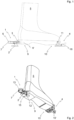
- a first embodiment of a heel element 1 according to the invention is shown in a touring ski binding according to the invention, in which touring ski binding a shoe 5 according to the invention is accommodated, wherein the heel element 1 is in a downhill mode.
- the touring ski binding comprises, in addition to the Heel element 1 a front element 4.
- the heel element 1 and the front element 4 can be mounted, in particular screwed, to a winter sports device, in particular a touring ski (not shown for reasons of clarity).
- the shoe 5 is rotatably held in the front element 4.
- retaining pins 11 also called “pins” of the front element 4 are provided, which retaining pins 11 engage in the shoe sole in a shoe tip area 10 of the shoe 5.
- known metal receptacles for the retaining pins 11 in the shoe sole are typically provided in the shoe tip area 10.
- the retaining pins 11 define a rotation axis which in Fig.1 is perpendicular to the drawing plane, or the shoe 5 can be rotated around the retaining pins 11 when the heel element 1 is in a touring mode.
- a lever mechanism 16 known per se is provided.
- the heel element 1 has a base body 2 and at least one retaining element 3 protruding from the base body 2, wherein in the embodiments shown two retaining elements 3 (usually also called “pins") are provided.
- the heel element 1 can be transferred back and forth between the downhill mode and the touring mode.
- the retaining elements 3 are arranged in such a way that they can be brought into engagement with the shoe 5 in order to fix the shoe 5 in the touring ski binding.
- a known receptacle is provided in the shoe sole in a heel area 9 of the shoe 5 for the retaining elements 3, which is typically made of metal. Accordingly, in the downhill mode, the shoe 5 cannot be rotated about the retaining pins 11.
- the heel element 1 is arranged such that the retaining elements 3 are not in engagement with the shoe 5, so that the shoe 5 is released in the heel section 9 and the shoe 5 can be rotated about the retaining pins 11 which hold the shoe 5 in the toe area 10, cf. Fig. 3 and Fig. 4 .
- the heel element 1 has a magnet 6 which is arranged in such a way that the shoe 5, which is rotatably held in the front element 4 of the touring ski binding, is repelled from the heel element 1 in touring mode if the shoe 5 has an oppositely polarized (ie repelling) oriented further magnet 6'.
- the latter is realized in the illustrated embodiments in such a way that the shoe 5 has a recess 12 in the heel section 9 in which the further magnet 6' is arranged, wherein in Fig.2 , Fig.4 , Fig.6 and Fig.8 the further magnet 6' as well as a cover or a closure of the recess 12 are not shown for reasons of clarity.
- the heel element 1 has a pin cover 7 which is rotatably or foldably mounted on the base body 2.
- the pin cover 7 can thus be folded out over the retaining elements 3 so that the pin cover 7 covers the retaining elements 3.
- the fixation of the shoe 5 in the front element 4 typically first has to be released using the lever mechanism 16 in order to release the shoe 5 from the touring ski binding.
- the touring ski binding is put back in place, with the shoe 5 being again fixed to the front element 4 using the lever mechanism 16 (rotatable).
- the pin cover 7 forms a stop for the shoe 5, see. Fig.3 , and thus functions as a climbing aid 8, which at least has a static effect.
- the pin cover 7 also forms a housing 13 in which the magnet 6 is accommodated, in which Fig.2 and Fig.4 the magnet 6 and a cover or closure of the housing 13 are not shown for reasons of clarity.
- the magnet 6 is arranged in such a way that the further magnet 6' is arranged as directly above the magnet 6 as possible when the shoe 5 is standing with its heel section 9 on the pin cover 7 or the climbing aid 8. Accordingly, due to the repulsive orientation of the poles of the magnets 6, 6', a maximum repulsive force acts between the magnets 6, 6', which prevents the user from lifting the heel section 9 of the shoe 5 (cf. Fig.4 ), which also makes the climbing aid 8 appear dynamic.
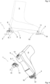
- the heel element 1 can be converted from the downhill mode to the touring mode and vice versa by rotating the base body 2 about a rotation axis 14.
- the heel element 1 has a climbing aid 8, with which a stop for the shoe 5 can be formed in the touring mode.
- the climbing aid 8 is part of the base body 2 and is preferably made in one piece with the base body 2.
- the base body 2 or the climbing aid 8 forms a housing 13 for the magnet 6, wherein in Fig.6 and Fig.8 the magnet 6 is not shown for reasons of clarity.
- Fig.5 the heel element 1 is shown in downhill mode, ie the heel element 1 is rotated so that the retaining elements 3 are in engagement with the shoe 5 in order to fix the shoe 5 in the touring ski binding.
- the heel element 1 is rotated about the rotation axis 14 into the touring mode, whereby the shoe 5 is first released from the front element 4 and thus from the touring ski binding by means of the lever mechanism 16.
- the heel element 1 is then rotated by 180° about the rotation axis 14, cf. Fig. 7 and Fig. 8 opposite Fig. 5 and Fig. 6 .
- the magnet 6 is also arranged so that the other magnet 6 ⁇ of the shoe 5 is arranged as directly above the magnet 6 as possible when the shoe 5 is standing with its heel section 9 on the climbing aid 8. Accordingly, due to the repulsive orientation of the poles of the magnets 6, 6', a maximum repulsive force acts between the magnets 6, 6', which prevents the user from lifting the heel section 9 of the shoe 5 (cf. Fig.8 ), which also makes the climbing aid 8 appear dynamic.
- one or more foldable climbing aids can be provided, whereby preferably at least one of the climbing aids can have a magnet in order to achieve a dynamic effect of the respective climbing aid.
- the shoe 5 can typically remain fixed in the front element 4 when the shoe is transferred from the touring mode to the downhill mode.
- the retaining elements 3 of the heel element 1 can be designed to be spring-loaded, for example.
- the retaining elements 3 in the first embodiment can slide off the section of the shoe 5 with which they are subsequently brought into engagement (or on the corresponding receptacle of the shoe 5) when the shoe 5, which is rotatably fixed to the front element 4, is pressed from above against the heel element 1 in the downhill mode, more precisely against the retaining elements 3, in order to finally lock into the said section.
- the retaining elements 3 can slide off the section of the shoe 5 with which they are subsequently brought into engagement (or on the corresponding seat of the shoe 5) and finally, after rotation, locks into the said section.
- the sliding of the spring-loaded retaining elements 3 is supported by the shape of the section of the shoe 5, in that the section has a correspondingly shaped, in particular ramp-shaped, contact surface for the retaining elements 3.
Landscapes
- Engineering & Computer Science (AREA)
- Mechanical Engineering (AREA)
- Footwear And Its Accessory, Manufacturing Method And Apparatuses (AREA)
Claims (10)
- Élément talon (1) destiné à une fixation de ski de randonnée, ledit élément talon (1) présentant au moins une partie principale (2) ainsi qu'au moins un élément de retenue (3) faisant saillie sur la partie principale (2), l'élément talon (1) étant transférable au moins en un mode descente et un mode randonnée, dans le mode descente, l'élément de retenue (3) étant disposé de façon à pouvoir être amené en prise avec une chaussure (5) retenue rotative dans un élément avant (4) de la fixation de ski de randonnée et ainsi fixer la chaussure (5) dans la fixation de ski de randonnée, et dans le mode randonnée, l'élément de retenue (3) étant disposé de façon à libérer la chaussure (5) retenue rotative dans l'élément avant (4) de la fixation de ski de randonnée, l'élément talon (1) présentant un aimant (6),l'élément talon (1) étant transférable du mode descente au mode randonnée par rotation de la partie principale (2) et l'élément talon (1) présentant au moins une aide à la montée (8), aide à la montée (8) avec laquelle une butée est formable pour la chaussure (5) en mode randonnée,l'aide à la montée (8) présentant l'aimant (6), l'aimant (6) étant de préférence logé dans l'aide à la montée (8) et/ou l'aide à la montée (8) formant plus préférablement un boîtier pour l'aimant (6),caractérisé en ce que l'aimant (6) est disposé de façon à repousser la chaussure (5) retenue rotative dans l'élément avant (4) de la fixation de ski de randonnée de l'élément talon (1) en mode randonnée, si la chaussure (5) présente un autre aimant (6') doté de pôles orientés à l'opposé, en ce que l'aimant (6) et l'autre aimant (6') de la chaussure (5) sont disposés l'un au-dessus de l'autre lorsque la chaussure (5) repose avec une section de talon (9) sur l'aide à la montée (8).
- Élément talon (1) selon la revendication 1, caractérisé en ce que la partie principale (2) présente l'aimant (6), l'aimant (6) étant de préférence logé dans la partie principale (2) et/ou la partie principale (2) formant plus préférablement un boîtier (13) pour l'aimant (6).
- Fixation de ski de randonnée comprenant un élément talon (1) selon l'une des revendications précédentes ainsi qu'un élément avant (1) destiné à recevoir de façon rotative une chaussure de ski (5).
- Chaussure (5) destinée à être utilisée en association avec une fixation de ski de randonnée selon la revendication 3 et/ou un équipement de sport, la chaussure (5) présentant au moins dans une section de talon (9) un autre aimant (6') pour obtenir une répulsion de la fixation de ski de randonnée et/ou de l'équipement de sport lorsque la fixation de ski de randonnée et/ou l'équipement de sport présente un aimant (6) doté de pôles orientés à l'opposé.
- Système comprenant une fixation de ski de randonnée selon la revendication 3 ainsi qu'une chaussure (5) selon la revendication 4.
- Système comprenant un équipement de sport ainsi qu'une chaussure (5) selon la revendication 4, un aimant (6) doté de pôles orientés à l'opposé de l'autre aimant (6') de la chaussure (5) étant reliable ou relié à l'équipement de sport de façon à ce que l'aimant (6) et l'autre aimant (6') puissent exercer une force de répulsion l'un sur l'autre dans un état de fonctionnement du système.
- Système selon la revendication 6, l'équipement de sport étant conçu comme un ski de fond et la chaussure (5) comme une chaussure de ski de fond.
- Système selon la revendication 6, l'équipement de sport étant conçu comme un ski-roller et la chaussure (5) comme une chaussure de ski-roller ou une chaussure de ski de fond.
- Système selon la revendication 6, l'équipement de sport étant conçu comme une raquette à neige et la chaussure (5) comme une chaussure de randonnée.
- Système selon la revendication 6, l'équipement de sport étant conçu comme un splitboard et la chaussure (5) comme une chaussure de snowboard.
Applications Claiming Priority (1)
| Application Number | Priority Date | Filing Date | Title |
|---|---|---|---|
| PCT/EP2020/080189 WO2022089731A1 (fr) | 2020-10-27 | 2020-10-27 | Élément talon pour fixation de ski de fond |
Publications (3)
| Publication Number | Publication Date |
|---|---|
| EP4132667A1 EP4132667A1 (fr) | 2023-02-15 |
| EP4132667C0 EP4132667C0 (fr) | 2024-05-22 |
| EP4132667B1 true EP4132667B1 (fr) | 2024-05-22 |
Family
ID=73288554
Family Applications (1)
| Application Number | Title | Priority Date | Filing Date |
|---|---|---|---|
| EP20804175.6A Active EP4132667B1 (fr) | 2020-10-27 | 2020-10-27 | Butee arriere de fixation de randonnee a ski |
Country Status (2)
| Country | Link |
|---|---|
| EP (1) | EP4132667B1 (fr) |
| WO (1) | WO2022089731A1 (fr) |
Citations (1)
| Publication number | Priority date | Publication date | Assignee | Title |
|---|---|---|---|---|
| EP2281615B1 (fr) * | 2009-08-05 | 2016-03-02 | Salewa Sport AG | Aide à la montée, fixation de ski de fond et équipement de ski |
Family Cites Families (3)
| Publication number | Priority date | Publication date | Assignee | Title |
|---|---|---|---|---|
| FR2974308A1 (fr) | 2011-04-21 | 2012-10-26 | Patrice Jean Andre Cornillon | Dispositif permettant la fixation d'un ressort aidant a la montee et a l'avancee pour planches de glisse (ski alpinisme, ski de randonnee, ski de fond) ou de marche (raquettes a neige) |
| ITTO20110598A1 (it) * | 2011-07-07 | 2013-01-08 | Elmi S R L | Puntale per attacco da sci o racchette da neve con sistema autocentrante magnetico |
| ITUB20169930A1 (it) * | 2016-01-12 | 2017-07-12 | Atk Race Srl | Talloniera con alza tacco per la pratica dello sci alpinismo |
-
2020
- 2020-10-27 WO PCT/EP2020/080189 patent/WO2022089731A1/fr not_active Ceased
- 2020-10-27 EP EP20804175.6A patent/EP4132667B1/fr active Active
Patent Citations (1)
| Publication number | Priority date | Publication date | Assignee | Title |
|---|---|---|---|---|
| EP2281615B1 (fr) * | 2009-08-05 | 2016-03-02 | Salewa Sport AG | Aide à la montée, fixation de ski de fond et équipement de ski |
Also Published As
| Publication number | Publication date |
|---|---|
| EP4132667C0 (fr) | 2024-05-22 |
| WO2022089731A1 (fr) | 2022-05-05 |
| EP4132667A1 (fr) | 2023-02-15 |
Similar Documents
| Publication | Publication Date | Title |
|---|---|---|
| AT504842B1 (de) | Multifunktionales gleitgerat | |
| EP2351603B1 (fr) | Fixation de ski dotée d'une aide à la montée | |
| DE19635250A1 (de) | Automatische Befestigungsvorrichtung | |
| DE202009019128U1 (de) | Zeheneinheit für Tourenskibindung | |
| EP3702005B1 (fr) | Talonnière | |
| DE102010029647A1 (de) | Tourenbindung | |
| DE102012208915B4 (de) | Ferseneinheit mit Steighilfe und Bremsanordnung | |
| DE102008050044B4 (de) | Skibindung | |
| EP3928842B1 (fr) | Unité avant pour une fixation de randonnée | |
| DE3151584A1 (de) | Bindungsgesamtheit eines schuhs mit einem ski, insbesondere einem langlaufski | |
| EP3195906B1 (fr) | Talonniere ayant une configuration de marche | |
| EP0581802B1 (fr) | Chaussure de sport | |
| EP4132667B1 (fr) | Butee arriere de fixation de randonnee a ski | |
| DE202013009713U1 (de) | Bremsvorrichtung für einen Tourenski mit integriertem einstellbaren Aufstiegskeil | |
| CH706664B1 (de) | Skibindung. | |
| DE69407060T2 (de) | Langlaufskischuh, -bindung und -schuheinheit | |
| EP2241355A2 (fr) | Fixation de ski | |
| EP4173682B1 (fr) | Fixation de ski, en particulier fixation de ski de randonnée | |
| EP3714952A1 (fr) | Dispositif de freinage | |
| EP2272574B1 (fr) | Aide à la montée pour un ski | |
| DE19531677A1 (de) | Snowboardbindung | |
| CH616852A5 (fr) | ||
| EP1715929A1 (fr) | Fixation de ski declenchable | |
| AT401732B (de) | Bindung für ein snowboard | |
| DE2661061C2 (de) | Langlaufbindung |
Legal Events
| Date | Code | Title | Description |
|---|---|---|---|
| STAA | Information on the status of an ep patent application or granted ep patent |
Free format text: STATUS: UNKNOWN |
|
| STAA | Information on the status of an ep patent application or granted ep patent |
Free format text: STATUS: THE INTERNATIONAL PUBLICATION HAS BEEN MADE |
|
| PUAI | Public reference made under article 153(3) epc to a published international application that has entered the european phase |
Free format text: ORIGINAL CODE: 0009012 |
|
| STAA | Information on the status of an ep patent application or granted ep patent |
Free format text: STATUS: REQUEST FOR EXAMINATION WAS MADE |
|
| 17P | Request for examination filed |
Effective date: 20221111 |
|
| AK | Designated contracting states |
Kind code of ref document: A1 Designated state(s): AL AT BE BG CH CY CZ DE DK EE ES FI FR GB GR HR HU IE IS IT LI LT LU LV MC MK MT NL NO PL PT RO RS SE SI SK SM TR |
|
| STAA | Information on the status of an ep patent application or granted ep patent |
Free format text: STATUS: EXAMINATION IS IN PROGRESS |
|
| 17Q | First examination report despatched |
Effective date: 20230619 |
|
| GRAP | Despatch of communication of intention to grant a patent |
Free format text: ORIGINAL CODE: EPIDOSNIGR1 |
|
| STAA | Information on the status of an ep patent application or granted ep patent |
Free format text: STATUS: GRANT OF PATENT IS INTENDED |
|
| DAV | Request for validation of the european patent (deleted) | ||
| DAX | Request for extension of the european patent (deleted) | ||
| INTG | Intention to grant announced |
Effective date: 20231220 |
|
| GRAS | Grant fee paid |
Free format text: ORIGINAL CODE: EPIDOSNIGR3 |
|
| GRAA | (expected) grant |
Free format text: ORIGINAL CODE: 0009210 |
|
| STAA | Information on the status of an ep patent application or granted ep patent |
Free format text: STATUS: THE PATENT HAS BEEN GRANTED |
|
| AK | Designated contracting states |
Kind code of ref document: B1 Designated state(s): AL AT BE BG CH CY CZ DE DK EE ES FI FR GB GR HR HU IE IS IT LI LT LU LV MC MK MT NL NO PL PT RO RS SE SI SK SM TR |
|
| REG | Reference to a national code |
Ref country code: GB Ref legal event code: FG4D Free format text: NOT ENGLISH |
|
| REG | Reference to a national code |
Ref country code: CH Ref legal event code: EP |
|
| REG | Reference to a national code |
Ref country code: DE Ref legal event code: R096 Ref document number: 502020008088 Country of ref document: DE |
|
| REG | Reference to a national code |
Ref country code: IE Ref legal event code: FG4D Free format text: LANGUAGE OF EP DOCUMENT: GERMAN |
|
| U01 | Request for unitary effect filed |
Effective date: 20240611 |
|
| U07 | Unitary effect registered |
Designated state(s): AT BE BG DE DK EE FI FR IT LT LU LV MT NL PT SE SI Effective date: 20240620 |
|
| PG25 | Lapsed in a contracting state [announced via postgrant information from national office to epo] |
Ref country code: IS Free format text: LAPSE BECAUSE OF FAILURE TO SUBMIT A TRANSLATION OF THE DESCRIPTION OR TO PAY THE FEE WITHIN THE PRESCRIBED TIME-LIMIT Effective date: 20240922 |
|
| PG25 | Lapsed in a contracting state [announced via postgrant information from national office to epo] |
Ref country code: HR Free format text: LAPSE BECAUSE OF FAILURE TO SUBMIT A TRANSLATION OF THE DESCRIPTION OR TO PAY THE FEE WITHIN THE PRESCRIBED TIME-LIMIT Effective date: 20240522 |
|
| PG25 | Lapsed in a contracting state [announced via postgrant information from national office to epo] |
Ref country code: GR Free format text: LAPSE BECAUSE OF FAILURE TO SUBMIT A TRANSLATION OF THE DESCRIPTION OR TO PAY THE FEE WITHIN THE PRESCRIBED TIME-LIMIT Effective date: 20240823 |
|
| PG25 | Lapsed in a contracting state [announced via postgrant information from national office to epo] |
Ref country code: ES Free format text: LAPSE BECAUSE OF FAILURE TO SUBMIT A TRANSLATION OF THE DESCRIPTION OR TO PAY THE FEE WITHIN THE PRESCRIBED TIME-LIMIT Effective date: 20240522 |
|
| PG25 | Lapsed in a contracting state [announced via postgrant information from national office to epo] |
Ref country code: PL Free format text: LAPSE BECAUSE OF FAILURE TO SUBMIT A TRANSLATION OF THE DESCRIPTION OR TO PAY THE FEE WITHIN THE PRESCRIBED TIME-LIMIT Effective date: 20240522 |
|
| PG25 | Lapsed in a contracting state [announced via postgrant information from national office to epo] |
Ref country code: PL Free format text: LAPSE BECAUSE OF FAILURE TO SUBMIT A TRANSLATION OF THE DESCRIPTION OR TO PAY THE FEE WITHIN THE PRESCRIBED TIME-LIMIT Effective date: 20240522 Ref country code: NO Free format text: LAPSE BECAUSE OF FAILURE TO SUBMIT A TRANSLATION OF THE DESCRIPTION OR TO PAY THE FEE WITHIN THE PRESCRIBED TIME-LIMIT Effective date: 20240822 Ref country code: IS Free format text: LAPSE BECAUSE OF FAILURE TO SUBMIT A TRANSLATION OF THE DESCRIPTION OR TO PAY THE FEE WITHIN THE PRESCRIBED TIME-LIMIT Effective date: 20240922 Ref country code: HR Free format text: LAPSE BECAUSE OF FAILURE TO SUBMIT A TRANSLATION OF THE DESCRIPTION OR TO PAY THE FEE WITHIN THE PRESCRIBED TIME-LIMIT Effective date: 20240522 Ref country code: GR Free format text: LAPSE BECAUSE OF FAILURE TO SUBMIT A TRANSLATION OF THE DESCRIPTION OR TO PAY THE FEE WITHIN THE PRESCRIBED TIME-LIMIT Effective date: 20240823 Ref country code: ES Free format text: LAPSE BECAUSE OF FAILURE TO SUBMIT A TRANSLATION OF THE DESCRIPTION OR TO PAY THE FEE WITHIN THE PRESCRIBED TIME-LIMIT Effective date: 20240522 Ref country code: RS Free format text: LAPSE BECAUSE OF FAILURE TO SUBMIT A TRANSLATION OF THE DESCRIPTION OR TO PAY THE FEE WITHIN THE PRESCRIBED TIME-LIMIT Effective date: 20240822 |
|
| U20 | Renewal fee for the european patent with unitary effect paid |
Year of fee payment: 5 Effective date: 20241022 |
|
| PG25 | Lapsed in a contracting state [announced via postgrant information from national office to epo] |
Ref country code: CZ Free format text: LAPSE BECAUSE OF FAILURE TO SUBMIT A TRANSLATION OF THE DESCRIPTION OR TO PAY THE FEE WITHIN THE PRESCRIBED TIME-LIMIT Effective date: 20240522 |
|
| PG25 | Lapsed in a contracting state [announced via postgrant information from national office to epo] |
Ref country code: RO Free format text: LAPSE BECAUSE OF FAILURE TO SUBMIT A TRANSLATION OF THE DESCRIPTION OR TO PAY THE FEE WITHIN THE PRESCRIBED TIME-LIMIT Effective date: 20240522 Ref country code: SK Free format text: LAPSE BECAUSE OF FAILURE TO SUBMIT A TRANSLATION OF THE DESCRIPTION OR TO PAY THE FEE WITHIN THE PRESCRIBED TIME-LIMIT Effective date: 20240522 |
|
| PG25 | Lapsed in a contracting state [announced via postgrant information from national office to epo] |
Ref country code: SK Free format text: LAPSE BECAUSE OF FAILURE TO SUBMIT A TRANSLATION OF THE DESCRIPTION OR TO PAY THE FEE WITHIN THE PRESCRIBED TIME-LIMIT Effective date: 20240522 Ref country code: RO Free format text: LAPSE BECAUSE OF FAILURE TO SUBMIT A TRANSLATION OF THE DESCRIPTION OR TO PAY THE FEE WITHIN THE PRESCRIBED TIME-LIMIT Effective date: 20240522 Ref country code: CZ Free format text: LAPSE BECAUSE OF FAILURE TO SUBMIT A TRANSLATION OF THE DESCRIPTION OR TO PAY THE FEE WITHIN THE PRESCRIBED TIME-LIMIT Effective date: 20240522 |
|
| REG | Reference to a national code |
Ref country code: DE Ref legal event code: R097 Ref document number: 502020008088 Country of ref document: DE |
|
| PLBE | No opposition filed within time limit |
Free format text: ORIGINAL CODE: 0009261 |
|
| STAA | Information on the status of an ep patent application or granted ep patent |
Free format text: STATUS: NO OPPOSITION FILED WITHIN TIME LIMIT |
|
| 26N | No opposition filed |
Effective date: 20250225 |
|
| REG | Reference to a national code |
Ref country code: CH Ref legal event code: PL |
|
| GBPC | Gb: european patent ceased through non-payment of renewal fee |
Effective date: 20241027 |
|
| PG25 | Lapsed in a contracting state [announced via postgrant information from national office to epo] |
Ref country code: MC Free format text: LAPSE BECAUSE OF FAILURE TO SUBMIT A TRANSLATION OF THE DESCRIPTION OR TO PAY THE FEE WITHIN THE PRESCRIBED TIME-LIMIT Effective date: 20240522 |
|
| PG25 | Lapsed in a contracting state [announced via postgrant information from national office to epo] |
Ref country code: GB Free format text: LAPSE BECAUSE OF NON-PAYMENT OF DUE FEES Effective date: 20241027 |
|
| PG25 | Lapsed in a contracting state [announced via postgrant information from national office to epo] |
Ref country code: CH Free format text: LAPSE BECAUSE OF NON-PAYMENT OF DUE FEES Effective date: 20241031 |
|
| PG25 | Lapsed in a contracting state [announced via postgrant information from national office to epo] |
Ref country code: IE Free format text: LAPSE BECAUSE OF NON-PAYMENT OF DUE FEES Effective date: 20241027 |
|
| U20 | Renewal fee for the european patent with unitary effect paid |
Year of fee payment: 6 Effective date: 20251023 |
|
| PG25 | Lapsed in a contracting state [announced via postgrant information from national office to epo] |
Ref country code: CY Free format text: LAPSE BECAUSE OF FAILURE TO SUBMIT A TRANSLATION OF THE DESCRIPTION OR TO PAY THE FEE WITHIN THE PRESCRIBED TIME-LIMIT; INVALID AB INITIO Effective date: 20201027 |
|
| PG25 | Lapsed in a contracting state [announced via postgrant information from national office to epo] |
Ref country code: HU Free format text: LAPSE BECAUSE OF FAILURE TO SUBMIT A TRANSLATION OF THE DESCRIPTION OR TO PAY THE FEE WITHIN THE PRESCRIBED TIME-LIMIT; INVALID AB INITIO Effective date: 20201027 |
|
| PG25 | Lapsed in a contracting state [announced via postgrant information from national office to epo] |
Ref country code: SM Free format text: LAPSE BECAUSE OF FAILURE TO SUBMIT A TRANSLATION OF THE DESCRIPTION OR TO PAY THE FEE WITHIN THE PRESCRIBED TIME-LIMIT; INVALID AB INITIO Effective date: 20201027 |