EP4134485A1 - Procédé de stabilisation du lit de ballast d'une voie - Google Patents
Procédé de stabilisation du lit de ballast d'une voie Download PDFInfo
- Publication number
- EP4134485A1 EP4134485A1 EP22186276.6A EP22186276A EP4134485A1 EP 4134485 A1 EP4134485 A1 EP 4134485A1 EP 22186276 A EP22186276 A EP 22186276A EP 4134485 A1 EP4134485 A1 EP 4134485A1
- Authority
- EP
- European Patent Office
- Prior art keywords
- track
- stabilizer
- dynamic
- residual
- vertical
- Prior art date
- Legal status (The legal status is an assumption and is not a legal conclusion. Google has not performed a legal analysis and makes no representation as to the accuracy of the status listed.)
- Granted
Links
Images



Classifications
-
- E—FIXED CONSTRUCTIONS
- E01—CONSTRUCTION OF ROADS, RAILWAYS, OR BRIDGES
- E01B—PERMANENT WAY; PERMANENT-WAY TOOLS; MACHINES FOR MAKING RAILWAYS OF ALL KINDS
- E01B27/00—Placing, renewing, working, cleaning, or taking-up the ballast, with or without concurrent work on the track; Devices therefor; Packing sleepers
- E01B27/12—Packing sleepers, with or without concurrent work on the track; Compacting track-carrying ballast
- E01B27/13—Packing sleepers, with or without concurrent work on the track
- E01B27/16—Sleeper-tamping machines
- E01B27/17—Sleeper-tamping machines combined with means for lifting, levelling or slewing the track
-
- E—FIXED CONSTRUCTIONS
- E01—CONSTRUCTION OF ROADS, RAILWAYS, OR BRIDGES
- E01B—PERMANENT WAY; PERMANENT-WAY TOOLS; MACHINES FOR MAKING RAILWAYS OF ALL KINDS
- E01B27/00—Placing, renewing, working, cleaning, or taking-up the ballast, with or without concurrent work on the track; Devices therefor; Packing sleepers
- E01B27/12—Packing sleepers, with or without concurrent work on the track; Compacting track-carrying ballast
- E01B27/20—Compacting the material of the track-carrying ballastway, e.g. by vibrating the track, by surface vibrators
-
- E—FIXED CONSTRUCTIONS
- E01—CONSTRUCTION OF ROADS, RAILWAYS, OR BRIDGES
- E01B—PERMANENT WAY; PERMANENT-WAY TOOLS; MACHINES FOR MAKING RAILWAYS OF ALL KINDS
- E01B35/00—Applications of measuring apparatus or devices for track-building purposes
- E01B35/06—Applications of measuring apparatus or devices for track-building purposes for measuring irregularities in longitudinal direction
Definitions
- the invention relates to a method for stabilizing the ballast bed of a track, with a track-mobile tamping machine, which aligns the track with a lifting device in a desired position, which fixes the track in the aligned position with a fully hydraulic tamping drive, which directional position fixed track with a dynamic track stabilizer stabilized by settlement and equipped with sensors to determine the properties of the ballast bed and a track measuring device.
- Track maintenance work such as tamping or cleaning the track reduces the resistance to lateral displacement by up to 60%.
- At temperatures above the bracing temperature there is compressive stress in the rails of the endlessly welded track. The rails tend to buckle. Trains running over the track bring in executives. If the resistance to lateral displacement is reduced, there is a risk of warping under the train. The result would be a derailment. Therefore, without using a dynamic track stabilizer, a speed-restriction section is set up after maintenance work such as tamping at high rail temperatures.
- the slow-moving trains have lower leaders, which eliminates the risk of warping.
- speed restrictions are undesirable, costly disruptions to operations.
- Rock piles such as railway ballast in particular, can be compacted efficiently, in particular by the action of horizontal vibrations, especially when the frequency is selected in such a way that the ballast adopts an elastoliquid behavior, which is the case at frequencies greater than or equal to 25 Hz.
- Dynamic track stabilization units serve to to compensate for irregular initial settlements of the track on the ballast bed through a targeted, controlled anticipation.
- Known dynamic track stabilizers are equipped with a mechanical or hydraulic vibration drive (EP2902546A1 ) fitted.
- the mechanical vibration drives have two counter-rotating eccentric masses.
- the two revolving eccentric masses are coupled via gear wheels in such a way that the masses rotate in opposite directions about assigned axes.
- the oscillating force components cancel out in the vertical direction and the oscillating force components in the horizontal direction, ie in a plane parallel to the track and transverse to the longitudinal direction of the track, amplify.
- eccentric drives in which the distance between the masses and the axis of rotation can be varied in order to be able to adjust the dynamic impact force ( WO2008009314A1 , EP3752675A1 ).
- the oscillating drive comprises at least one cylinder vibrator, which is controlled via a proportional valve or a servo valve and is formed by at least one hydraulic cylinder.
- a particular disadvantage of using the dynamic track stabilizer is that the settlements achieved are uneven.
- the use of the dynamic track stabilizer reduces the height of the track. This means a reduction in the durability of the track geometry and, associated with this, a reduction in the duration of the maintenance cycle.
- a continuous dynamic transverse displacement resistance measuring device which is based on the principle of measuring the hydraulic drive power of the mechanical oscillating unit and equating it with the friction power of the track on the ballast.
- the friction loss can be calculated by measuring the superimposed load as a normal force and the coefficient of friction of the sleeper on the ballast, which is also referred to as the transverse displacement resistance.
- the displacement resistance is not measured directly, but indirectly.
- the transverse displacement resistance is the determining, safety-critical variable for the warping safety of a continuously welded track.
- the lateral displacement resistance is usually determined at a displacement of 2 mm for a loosened, unloaded sleeper.
- the typical vibration amplitudes of the track with dynamic slide stabilizers are around 2 to 3 mm.
- the transverse displacement resistance is one of the most important safety-critical variables in track construction and is usually determined by complex individual sleeper measurements, usually under an unwanted track block.
- the stabilization frequency can be adjusted from 20Hz to 40Hz.
- the invention is based on the object of specifying a method which takes into account the influence of the ballast bed properties and the heave values in the dynamic stabilization.
- the invention is intended to take into account the remaining track defects after the tamping and the track defects occurring after the stabilization and thereby minimize the total track defects after the stabilization.
- Advantageous is the resulting greater wear reserve, the extension of the maintenance cycles, the corresponding cost savings and the reduction in operational difficulties and the associated costs.
- the invention solves the problem in that a first inertial navigation system is arranged between the tamping drive and the dynamic track stabilizer, which measures the residual track geometry error after the tamping machine, and that a second inertial navigation system is arranged in the working direction behind the dynamic track stabilizer, which measures the residual track geometry error behind the
- the track stabilizer measures that a control variable is derived from a similarity transformation of the residual track geometry errors to one another, which is linked to a setting specification and is routed via a controller whose output signal is linked to predeterminable precontrol variables and that at least one control parameter of the dynamic track stabilizer is regulated in such a way that the residual track geometry error behind the track stabilizer becomes minimal.
- the residual track geometry errors can be determined on the one hand after the tamping and before the track stabilization and on the other hand also after the track stabilization by means of the measurement data of the two inertial navigation systems.
- the residual track geometry errors are calculated from the distance between the currently measured track position and the specified target position.
- a controlled variable for the dynamic track stabilizer is derived from the residual track geometry errors in order to minimize the residual track geometry errors after the dynamic track stabilizer.
- the simplest similarity transformation for deriving a controlled variable from the residual track geometry errors would be to minimize the ratio of the root mean square values of the two residual track geometry errors, i.e. to use the least squares method, which is a standard mathematical procedure of the adjustment calculation.
- the measures according to the invention result in a method which takes both lifting values and ballast properties into account and by comparing residual track geometry errors after tamping with residual track geometry errors after stabilization and corresponding control of the track stabilizer parameters such as frequency, eccentricity and/or or vertical ballast, the minimizes residual track error with a controller, optionally including a controller with a machine learning computer.
- This computer can use statistical methods to exclude improbable parameter ranges and prioritize highly probable parameter ranges from empirical values such as the condition of the ballast, the number of kilometers of track, including empirical values from previous work processes.
- the dynamic impact force is to be controlled, this can be done by the effective eccentricity, the eccentric mass or the frequency.
- the impact power depends quadratically on the frequency and linearly on the other variables. Therefore, changing the frequency has the greatest influence on the impact force and thus on the settlement.
- the wheels of the DGS are hydraulically pressed onto the rail on both sides via telescopic axles. With the help of the lateral rollers, the rails are clamped by the DGS so that the impact force can be transferred well. If the pressure in the telescopic cylinders of the telescopic axles is measured using pressure sensors, then the dynamic impact force can be measured directly. In this way, the dynamic impact force can be easily recorded as a manipulated variable.
- An acceleration sensor mounted on the DGS housing measures the acceleration. From this, the oscillation frequency can be recorded and used as an actual value for regulation.
- the influence of the vertical track stiffness on the settlement can be recorded with the computer with machine learning capabilities and used for control.
- the influence of the vertical track stiffness is taken into account as a pre-control variable.
- a device according to the invention which influences the settlement via the oscillation frequency, allows particularly high control speeds of the system.
- traditional eccentric systems with hydraulic eccentric adjustment have a considerable adjustment time due to high time constants.
- a vertical vibration of the load cylinder not only leads to an improved controllability of the settlement differences between the left and right side of the track, but in general to a higher compaction effect and better settlements, which also increases the durability of the geometric track geometry.
- the previous lifting values and the associated loosening of the track and the properties of the ballast bed can be taken into account.
- Larger elevations undoubtedly lead to a greater disruption of the grain interlocking under the sleepers and, as a result, to higher and irregular settlements and the resulting track defects.
- the ballast properties in particular the degree of soiling and wear, there are also different track settlements.
- the invention there is the possibility of automatically adapting the track stabilizer parameters to the most varied of ballast conditions or the previous elevations. To do this, either the vertical load and/or the dynamic impact force is regulated. The track errors resulting from the stabilization or the residual errors remaining after the track has been tamped are taken into account.
- a device for tamping and stabilizing the ballast bed of a track 2 comprises a tamping machine 1 and a trailer 4 with dynamic track stabilization units 9, DGS units for short, which work in the working direction A.
- the DGS aggregates 9 are supported by vertical load cylinders 10 on the frame of the trailer 4 and with the Load cylinders 10 pressed against the rail 2.
- the tamping machine 1 and the trailer 4 rest on running gears 3.
- the tamping machine 1 has a track measuring device consisting of three measuring carriages 7a-c with a measuring chord 8 stretched between them, a tamping unit 5 and a lifting and straightening device 6.
- the measuring chord 8 of the Track surveying device with the length I has a pitch a, b.
- the rear measuring carriage of the tamping machine forms on the one hand the rear end of the measuring chord 8 and on the other hand carries a first inertial navigation system 7c with the help of which the position of the track after tamping is measured and recorded and a residual track geometry error based on a target position is evaluated.
- Another measuring car with an inertial navigation system 7d is provided for measuring the residual track geometry error after the track stabilization in the rear area of the trailer 4, ie in the working direction A behind the track stabilizer 9.
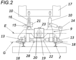
- FIG. 2 schematically represents a DGS unit 9.
- Two unbalanced masses 19 are operated in opposite directions in such a way that the vertical components cancel each other out and the forces in the horizontal direction 20 in the effective plane E add up, resulting in a track-parallel oscillation.
- the track 2 is vibrated primarily in the horizontal transverse direction.
- the wheels 13 are pressed against the rails 2 via telescopic cylinders 22 .
- the rail 2 is clamped in via external roller clamps 18 .
- the accelerations and the oscillation frequency f are measured via an acceleration sensor 23 on the DGS unit 9 .
- the dynamic impact force is measured via pressure sensors 28 .
- the rollers 18 are pressed onto the rail 2 via a lever 14 and a drive.
- Vertical load cylinders 10 are supported on the frame 17 of the trailer and press the DGS unit 9 vertically against the rails 2.
- the loading cylinders 10 are equipped with an integrated path measuring system 15 and a pressure sensor 16.
- the force with which the stabilization unit 9 is pressed against the track 2 while being supported on the machine frame 17 can thus be adjusted via the adjusting cylinder.
- the adjusting cylinders 10 form a regulated or controlled by a proportional or servo valve 21 cylinder vibrator.
- the position of the adjusting cylinder piston is measured with a sensor 15 and a pressure sensor 16 measuring the hydraulic pressure is assigned to the adjusting cylinders in order to determine a static and dynamic vertical rigidity of the track.
- FIG. 3 shows schematically a control circuit according to the invention.
- the residual track geometry error RF1 is measured downstream of the tamping machine
- the second inertial navigation system 7d arranged behind the dynamic track stabilizer 9 in working direction A
- the residual track geometry error RF2 downstream of the track stabilizer 9 is measured.
- a control variable is derived from the residual track geometry errors RF1, RF2 via a similarity transformation of the residual track geometry errors RF1, RF2, which is linked to a setting specification WS and is routed via a controller K, whose output signal is linked to predeterminable pilot variables.
- At least one control parameter OUT of the dynamic track stabilizer 9 is thus regulated in such a way that the residual track geometry error RF2 behind the track stabilizer 9 becomes minimal.
- the fully hydraulic tamping unit 5 records the ballast bed properties such as ballast bed hardness and compaction force via its sensors, in particular by measuring the power introduced into the ballast bed or its derivatives. From this, the pilot variable F(BS) (a function dependent on the hardness of the ballast bed BS) is derived and fed to the control loop.
- the pilot variable F(C) is specified via the dynamic vertical stiffness C dynvert of the track. The harder the vertical rigidity, the less settlement there is.
- the pilot control variable F(H) is calculated by the track management computer 6 as a function of the lifting values H and supplied to the control loop. The greater the heave H, the greater the settlement.
- the residual error RF1 measured with the navigation system 7c and the residual error measured with the navigation system 7d are supplied to the computer 11. This performs a similarity transformation between the residual errors with the aim of minimizing the ripples (amplitudes) of the settlements according to the DGS.
- the simplest similarity transformation would be to minimize the root mean square ratio of RF2 to RF1. The smaller this value, the more the goal of minimizing the residual error is achieved.
- the absolute settlement of the track is irrelevant - it does not affect the wheel-rail interaction of the trains running over it.
- the control loop controller K is supplied with the control deviation and uses it to generate the manipulated variable OUT for the DGS 9.
- OUT can be the controlled frequency f, the vertical dynamic (or static) load F dynvert or the eccentricity m exz / e or a combination of these.
- a target setting is specified via WS.
- the control loop regulates the system in such a way that this settlement is achieved as consistently as possible over the entire processed section.
- FIG. 4 shows a schematic of the control arrangement when using one of the controllers K, which includes a computer with machine learning capability KI/11.
- the bedding hardness BS, the heave values of the tamping machine H, the vertical dynamic stiffness C dynvert and the residual errors RF1 and RF2 are read into the machine learning network KI/11. From this, the system learns to control the DGS parameters in such a way that the settlement errors after the DGS are minimized.
- OUT can be the regulated frequency f, vertical dynamic (or static) load F dynvert or eccentricity m exz / e or a combination of these.
- the machine learning system itself evaluates the influence of the parameters ballast bed hardness BS, heave values H and dynamic track stiffness C dynvert or the relationship between these variables and the settlement.
- the algorithm works with the aim of minimizing the residual errors RF1 and RF2.
- FIG. 5 shows the interaction of the components.
- the track position computer 12 delivers the lift values to the control computer 11/KI in a location-related manner.
- the values are location-related, the distance covered on the track is measured using an odometer 24 measured.
- the compaction path and compaction force are read by the sensors 27, 26 of the tamping units.
- the ballast bed properties are calculated from this.
- the controller K controls the parameters of the DGS 9.
- the residual error signals from the inertial navigation system units 7c and 7d are read into the control computer 11/KI. This communicates bidirectionally with the controller K and supplies it with the specifications for controlling the DGS 9.
Landscapes
- Engineering & Computer Science (AREA)
- Architecture (AREA)
- Civil Engineering (AREA)
- Structural Engineering (AREA)
- Machines For Laying And Maintaining Railways (AREA)
Applications Claiming Priority (1)
| Application Number | Priority Date | Filing Date | Title |
|---|---|---|---|
| ATA50654/2021A AT525090B1 (de) | 2021-08-12 | 2021-08-12 | Verfahren zum Stabilisieren der Schotterbettung eines Gleises |
Publications (3)
| Publication Number | Publication Date |
|---|---|
| EP4134485A1 true EP4134485A1 (fr) | 2023-02-15 |
| EP4134485B1 EP4134485B1 (fr) | 2024-02-14 |
| EP4134485C0 EP4134485C0 (fr) | 2024-02-14 |
Family
ID=82656762
Family Applications (1)
| Application Number | Title | Priority Date | Filing Date |
|---|---|---|---|
| EP22186276.6A Active EP4134485B1 (fr) | 2021-08-12 | 2022-07-21 | Procédé de stabilisation du lit de ballast d'une voie |
Country Status (2)
| Country | Link |
|---|---|
| EP (1) | EP4134485B1 (fr) |
| AT (1) | AT525090B1 (fr) |
Cited By (2)
| Publication number | Priority date | Publication date | Assignee | Title |
|---|---|---|---|---|
| CN118007482A (zh) * | 2024-02-07 | 2024-05-10 | 中国铁建高新装备股份有限公司 | 一种稳定道床的控制系统、控制方法、轨道养护车及介质 |
| AT527563A1 (de) * | 2023-08-28 | 2025-03-15 | Hp3 Real Gmbh | Verfahren zur Verbesserung der Gleisberichtigungsverfahren |
Citations (7)
| Publication number | Priority date | Publication date | Assignee | Title |
|---|---|---|---|---|
| WO2008009314A1 (fr) | 2006-07-20 | 2008-01-24 | Franz Plasser Bahnbaumaschinen-Industriegesellschaft Mbh | Procédé et machine de stabilisation d'une voie |
| EP2902546A1 (fr) | 2014-01-30 | 2015-08-05 | System7-Railsupport GmbH | Dispositif de compression du lit de ballast d'une voie ferrée |
| EP3209832A1 (fr) | 2014-10-22 | 2017-08-30 | HP3 Real GmbH | Procédé permettant de mesurer et de représenter la géométrie des rails d'une voie ferrée |
| WO2018082798A1 (fr) * | 2016-11-04 | 2018-05-11 | Plasser & Theurer Export Von Bahnbaumaschinen Gesellschaft M.B.H. | Procédé et engin de pose de voie permettant de corriger des défauts de géométrie de la voie |
| WO2019140467A1 (fr) * | 2018-01-22 | 2019-07-25 | Hp3 Real Gmbh | Procédé d'amélioration de la position d'une voie ferrée par une machine de bourrage de voies pouvant circuler sur des voies ferrées |
| WO2020233933A1 (fr) * | 2019-05-23 | 2020-11-26 | Plasser & Theurer Export Von Bahnbaumaschinen Gesellschaft M.B.H. | Procédé et dispositif de commande/régulation d'un entraînement rotatif d'un organe de travail d'une machine de pose de voies |
| EP3752675A1 (fr) | 2018-02-13 | 2020-12-23 | Plasser & Theurer Export von Bahnbaumaschinen GmbH | Machine pour la stabilisation d'une voie ferrée |
-
2021
- 2021-08-12 AT ATA50654/2021A patent/AT525090B1/de active
-
2022
- 2022-07-21 EP EP22186276.6A patent/EP4134485B1/fr active Active
Patent Citations (7)
| Publication number | Priority date | Publication date | Assignee | Title |
|---|---|---|---|---|
| WO2008009314A1 (fr) | 2006-07-20 | 2008-01-24 | Franz Plasser Bahnbaumaschinen-Industriegesellschaft Mbh | Procédé et machine de stabilisation d'une voie |
| EP2902546A1 (fr) | 2014-01-30 | 2015-08-05 | System7-Railsupport GmbH | Dispositif de compression du lit de ballast d'une voie ferrée |
| EP3209832A1 (fr) | 2014-10-22 | 2017-08-30 | HP3 Real GmbH | Procédé permettant de mesurer et de représenter la géométrie des rails d'une voie ferrée |
| WO2018082798A1 (fr) * | 2016-11-04 | 2018-05-11 | Plasser & Theurer Export Von Bahnbaumaschinen Gesellschaft M.B.H. | Procédé et engin de pose de voie permettant de corriger des défauts de géométrie de la voie |
| WO2019140467A1 (fr) * | 2018-01-22 | 2019-07-25 | Hp3 Real Gmbh | Procédé d'amélioration de la position d'une voie ferrée par une machine de bourrage de voies pouvant circuler sur des voies ferrées |
| EP3752675A1 (fr) | 2018-02-13 | 2020-12-23 | Plasser & Theurer Export von Bahnbaumaschinen GmbH | Machine pour la stabilisation d'une voie ferrée |
| WO2020233933A1 (fr) * | 2019-05-23 | 2020-11-26 | Plasser & Theurer Export Von Bahnbaumaschinen Gesellschaft M.B.H. | Procédé et dispositif de commande/régulation d'un entraînement rotatif d'un organe de travail d'une machine de pose de voies |
Cited By (2)
| Publication number | Priority date | Publication date | Assignee | Title |
|---|---|---|---|---|
| AT527563A1 (de) * | 2023-08-28 | 2025-03-15 | Hp3 Real Gmbh | Verfahren zur Verbesserung der Gleisberichtigungsverfahren |
| CN118007482A (zh) * | 2024-02-07 | 2024-05-10 | 中国铁建高新装备股份有限公司 | 一种稳定道床的控制系统、控制方法、轨道养护车及介质 |
Also Published As
| Publication number | Publication date |
|---|---|
| AT525090B1 (de) | 2022-12-15 |
| EP4134485B1 (fr) | 2024-02-14 |
| AT525090A4 (de) | 2022-12-15 |
| EP4134485C0 (fr) | 2024-02-14 |
Similar Documents
| Publication | Publication Date | Title |
|---|---|---|
| EP2902546B2 (fr) | Dispositif de compression du lit de ballast d'une voie ferrée | |
| EP3870760B1 (fr) | Procédé et machine pour stabiliser une voie ferrée | |
| AT402519B (de) | Kontinuierlich verfahrbare gleisbaumaschine zum verdichten der schotterbettung eines gleises | |
| DE69423048T2 (de) | Regelung für eine verfestigungsmaschine mit messeinrichtung für die eigenschaften des grundmaterials | |
| DE4102872C2 (de) | Kontinuierlich verfahrbare Gleisbaumaschine zum Verdichten der Schotterbettung und Verfahren zur kontinuierlichen Absenkung des Gleises | |
| EP2627826B1 (fr) | Méthode pour la détermination de la rigidité et/ou de l'amortissement d'un domaine d'une solidité | |
| EP4134485B1 (fr) | Procédé de stabilisation du lit de ballast d'une voie | |
| EP0688902A1 (fr) | Méthode de mesure de la résistance aux déplacements latéraux des rails d'une voie ferrée | |
| EP2957674A1 (fr) | Procédé de réglage de voie ferrée destiné au fonctionnement d'une machine de voie pouvant se déplacer sur une installation de voie ferrée | |
| EP3743561B1 (fr) | Procédé d'amélioration de la position d'une voie ferrée par une machine de bourrage de voies pouvant circuler sur des voies ferrées | |
| DE102016004298A1 (de) | Temperaturabhängige autoadaptive Verdichtung | |
| EP3239398A1 (fr) | Unité de bourrage pour une bourreuse | |
| AT524861B1 (de) | Verfahren und Maschine zum Stopfen eines Gleises | |
| DE3132708C2 (de) | Gleisstopf-Nivellier-und Richtmaschine mit Stabilisationsaggregat und Verfahren zum Verdichten der Schotterbettung eines zu korrigierenden Gleises | |
| WO2024052306A1 (fr) | Procédé et dispositif de détermination de la qualité, en particulier du degré de compactage, d'un lit de voie | |
| EP4073318B1 (fr) | Machine et procédé de stabilisation d'une voie ferrée à ballast | |
| DE102017106559B4 (de) | Auslegung oder Durchführung einer Bewegungsaufgabe einer bewegten Masse in einer mechanischen Anlage entlang zumindest einer Bewegungsachse | |
| EP1708058B1 (fr) | Procédé pour compenser les suroscillations d'un axe principal | |
| DE102006016375B4 (de) | Verfahren und Einrichtung zum Bestimmen der Kernerstarrung und/oder der Sumpfspitze beim Stranggießen von Metallen, insbesondere von Stahlwerkstoffen | |
| EP3315668B1 (fr) | Procédé et système pour la compaction d'un sol | |
| AT524860B1 (de) | Vorrichtung und Verfahren zum Verdichten eines Gleisbettes | |
| AT372437B (de) | Verfahren zum verdichten der schotterbettung eines zu korrigierenden gleises | |
| AT503437B1 (de) | Verfahren zum unterstopfen und stabilisieren eines gleises | |
| DE102019130324A1 (de) | Verfahren zum Betrieb eines Arbeitsprozesses | |
| WO2020253899A1 (fr) | Ensemble comprenant un four à coke et un train de roulement, ainsi que procédé de positionnement d'outils d'utilisation du four par rapport à un four à coke |
Legal Events
| Date | Code | Title | Description |
|---|---|---|---|
| PUAI | Public reference made under article 153(3) epc to a published international application that has entered the european phase |
Free format text: ORIGINAL CODE: 0009012 |
|
| STAA | Information on the status of an ep patent application or granted ep patent |
Free format text: STATUS: THE APPLICATION HAS BEEN PUBLISHED |
|
| AK | Designated contracting states |
Kind code of ref document: A1 Designated state(s): AL AT BE BG CH CY CZ DE DK EE ES FI FR GB GR HR HU IE IS IT LI LT LU LV MC MK MT NL NO PL PT RO RS SE SI SK SM TR |
|
| P01 | Opt-out of the competence of the unified patent court (upc) registered |
Effective date: 20230513 |
|
| STAA | Information on the status of an ep patent application or granted ep patent |
Free format text: STATUS: REQUEST FOR EXAMINATION WAS MADE |
|
| 17P | Request for examination filed |
Effective date: 20230725 |
|
| RBV | Designated contracting states (corrected) |
Designated state(s): AL AT BE BG CH CY CZ DE DK EE ES FI FR GB GR HR HU IE IS IT LI LT LU LV MC MK MT NL NO PL PT RO RS SE SI SK SM TR |
|
| GRAP | Despatch of communication of intention to grant a patent |
Free format text: ORIGINAL CODE: EPIDOSNIGR1 |
|
| STAA | Information on the status of an ep patent application or granted ep patent |
Free format text: STATUS: GRANT OF PATENT IS INTENDED |
|
| RIC1 | Information provided on ipc code assigned before grant |
Ipc: E01B 35/06 20060101ALI20230809BHEP Ipc: E01B 27/20 20060101ALI20230809BHEP Ipc: E01B 27/17 20060101AFI20230809BHEP |
|
| INTG | Intention to grant announced |
Effective date: 20230905 |
|
| GRAS | Grant fee paid |
Free format text: ORIGINAL CODE: EPIDOSNIGR3 |
|
| GRAA | (expected) grant |
Free format text: ORIGINAL CODE: 0009210 |
|
| STAA | Information on the status of an ep patent application or granted ep patent |
Free format text: STATUS: THE PATENT HAS BEEN GRANTED |
|
| AK | Designated contracting states |
Kind code of ref document: B1 Designated state(s): AL AT BE BG CH CY CZ DE DK EE ES FI FR GB GR HR HU IE IS IT LI LT LU LV MC MK MT NL NO PL PT RO RS SE SI SK SM TR |
|
| REG | Reference to a national code |
Ref country code: GB Ref legal event code: FG4D Free format text: NOT ENGLISH |
|
| REG | Reference to a national code |
Ref country code: CH Ref legal event code: EP |
|
| REG | Reference to a national code |
Ref country code: DE Ref legal event code: R096 Ref document number: 502022000499 Country of ref document: DE |
|
| REG | Reference to a national code |
Ref country code: IE Ref legal event code: FG4D Free format text: LANGUAGE OF EP DOCUMENT: GERMAN |
|
| U01 | Request for unitary effect filed |
Effective date: 20240312 |
|
| U07 | Unitary effect registered |
Designated state(s): AT BE BG DE DK EE FI FR IT LT LU LV MT NL PT SE SI Effective date: 20240319 |
|
| P04 | Withdrawal of opt-out of the competence of the unified patent court (upc) registered |
Effective date: 20240412 |
|
| PG25 | Lapsed in a contracting state [announced via postgrant information from national office to epo] |
Ref country code: IS Free format text: LAPSE BECAUSE OF FAILURE TO SUBMIT A TRANSLATION OF THE DESCRIPTION OR TO PAY THE FEE WITHIN THE PRESCRIBED TIME-LIMIT Effective date: 20240614 |
|
| PG25 | Lapsed in a contracting state [announced via postgrant information from national office to epo] |
Ref country code: GR Free format text: LAPSE BECAUSE OF FAILURE TO SUBMIT A TRANSLATION OF THE DESCRIPTION OR TO PAY THE FEE WITHIN THE PRESCRIBED TIME-LIMIT Effective date: 20240515 |
|
| PG25 | Lapsed in a contracting state [announced via postgrant information from national office to epo] |
Ref country code: RS Free format text: LAPSE BECAUSE OF FAILURE TO SUBMIT A TRANSLATION OF THE DESCRIPTION OR TO PAY THE FEE WITHIN THE PRESCRIBED TIME-LIMIT Effective date: 20240514 Ref country code: HR Free format text: LAPSE BECAUSE OF FAILURE TO SUBMIT A TRANSLATION OF THE DESCRIPTION OR TO PAY THE FEE WITHIN THE PRESCRIBED TIME-LIMIT Effective date: 20240214 |
|
| PG25 | Lapsed in a contracting state [announced via postgrant information from national office to epo] |
Ref country code: ES Free format text: LAPSE BECAUSE OF FAILURE TO SUBMIT A TRANSLATION OF THE DESCRIPTION OR TO PAY THE FEE WITHIN THE PRESCRIBED TIME-LIMIT Effective date: 20240214 |
|
| PG25 | Lapsed in a contracting state [announced via postgrant information from national office to epo] |
Ref country code: RS Free format text: LAPSE BECAUSE OF FAILURE TO SUBMIT A TRANSLATION OF THE DESCRIPTION OR TO PAY THE FEE WITHIN THE PRESCRIBED TIME-LIMIT Effective date: 20240514 Ref country code: NO Free format text: LAPSE BECAUSE OF FAILURE TO SUBMIT A TRANSLATION OF THE DESCRIPTION OR TO PAY THE FEE WITHIN THE PRESCRIBED TIME-LIMIT Effective date: 20240514 Ref country code: IS Free format text: LAPSE BECAUSE OF FAILURE TO SUBMIT A TRANSLATION OF THE DESCRIPTION OR TO PAY THE FEE WITHIN THE PRESCRIBED TIME-LIMIT Effective date: 20240614 Ref country code: HR Free format text: LAPSE BECAUSE OF FAILURE TO SUBMIT A TRANSLATION OF THE DESCRIPTION OR TO PAY THE FEE WITHIN THE PRESCRIBED TIME-LIMIT Effective date: 20240214 Ref country code: GR Free format text: LAPSE BECAUSE OF FAILURE TO SUBMIT A TRANSLATION OF THE DESCRIPTION OR TO PAY THE FEE WITHIN THE PRESCRIBED TIME-LIMIT Effective date: 20240515 Ref country code: ES Free format text: LAPSE BECAUSE OF FAILURE TO SUBMIT A TRANSLATION OF THE DESCRIPTION OR TO PAY THE FEE WITHIN THE PRESCRIBED TIME-LIMIT Effective date: 20240214 |
|
| PG25 | Lapsed in a contracting state [announced via postgrant information from national office to epo] |
Ref country code: PL Free format text: LAPSE BECAUSE OF FAILURE TO SUBMIT A TRANSLATION OF THE DESCRIPTION OR TO PAY THE FEE WITHIN THE PRESCRIBED TIME-LIMIT Effective date: 20240214 |
|
| PG25 | Lapsed in a contracting state [announced via postgrant information from national office to epo] |
Ref country code: PL Free format text: LAPSE BECAUSE OF FAILURE TO SUBMIT A TRANSLATION OF THE DESCRIPTION OR TO PAY THE FEE WITHIN THE PRESCRIBED TIME-LIMIT Effective date: 20240214 |
|
| U20 | Renewal fee for the european patent with unitary effect paid |
Year of fee payment: 3 Effective date: 20240729 |
|
| PG25 | Lapsed in a contracting state [announced via postgrant information from national office to epo] |
Ref country code: SM Free format text: LAPSE BECAUSE OF FAILURE TO SUBMIT A TRANSLATION OF THE DESCRIPTION OR TO PAY THE FEE WITHIN THE PRESCRIBED TIME-LIMIT Effective date: 20240214 |
|
| PG25 | Lapsed in a contracting state [announced via postgrant information from national office to epo] |
Ref country code: CZ Free format text: LAPSE BECAUSE OF FAILURE TO SUBMIT A TRANSLATION OF THE DESCRIPTION OR TO PAY THE FEE WITHIN THE PRESCRIBED TIME-LIMIT Effective date: 20240214 |
|
| PG25 | Lapsed in a contracting state [announced via postgrant information from national office to epo] |
Ref country code: SK Free format text: LAPSE BECAUSE OF FAILURE TO SUBMIT A TRANSLATION OF THE DESCRIPTION OR TO PAY THE FEE WITHIN THE PRESCRIBED TIME-LIMIT Effective date: 20240214 |
|
| PG25 | Lapsed in a contracting state [announced via postgrant information from national office to epo] |
Ref country code: SM Free format text: LAPSE BECAUSE OF FAILURE TO SUBMIT A TRANSLATION OF THE DESCRIPTION OR TO PAY THE FEE WITHIN THE PRESCRIBED TIME-LIMIT Effective date: 20240214 Ref country code: SK Free format text: LAPSE BECAUSE OF FAILURE TO SUBMIT A TRANSLATION OF THE DESCRIPTION OR TO PAY THE FEE WITHIN THE PRESCRIBED TIME-LIMIT Effective date: 20240214 Ref country code: RO Free format text: LAPSE BECAUSE OF FAILURE TO SUBMIT A TRANSLATION OF THE DESCRIPTION OR TO PAY THE FEE WITHIN THE PRESCRIBED TIME-LIMIT Effective date: 20240214 Ref country code: CZ Free format text: LAPSE BECAUSE OF FAILURE TO SUBMIT A TRANSLATION OF THE DESCRIPTION OR TO PAY THE FEE WITHIN THE PRESCRIBED TIME-LIMIT Effective date: 20240214 |
|
| REG | Reference to a national code |
Ref country code: DE Ref legal event code: R097 Ref document number: 502022000499 Country of ref document: DE |
|
| PLBE | No opposition filed within time limit |
Free format text: ORIGINAL CODE: 0009261 |
|
| STAA | Information on the status of an ep patent application or granted ep patent |
Free format text: STATUS: NO OPPOSITION FILED WITHIN TIME LIMIT |
|
| 26N | No opposition filed |
Effective date: 20241115 |
|
| PG25 | Lapsed in a contracting state [announced via postgrant information from national office to epo] |
Ref country code: MC Free format text: LAPSE BECAUSE OF FAILURE TO SUBMIT A TRANSLATION OF THE DESCRIPTION OR TO PAY THE FEE WITHIN THE PRESCRIBED TIME-LIMIT Effective date: 20240214 |
|
| PG25 | Lapsed in a contracting state [announced via postgrant information from national office to epo] |
Ref country code: IE Free format text: LAPSE BECAUSE OF NON-PAYMENT OF DUE FEES Effective date: 20240721 |
|
| U20 | Renewal fee for the european patent with unitary effect paid |
Year of fee payment: 4 Effective date: 20250728 |
|
| PG25 | Lapsed in a contracting state [announced via postgrant information from national office to epo] |
Ref country code: CY Free format text: LAPSE BECAUSE OF FAILURE TO SUBMIT A TRANSLATION OF THE DESCRIPTION OR TO PAY THE FEE WITHIN THE PRESCRIBED TIME-LIMIT; INVALID AB INITIO Effective date: 20220721 |
|
| REG | Reference to a national code |
Ref country code: CH Ref legal event code: H13 Free format text: ST27 STATUS EVENT CODE: U-0-0-H10-H13 (AS PROVIDED BY THE NATIONAL OFFICE) Effective date: 20260224 |
|
| PG25 | Lapsed in a contracting state [announced via postgrant information from national office to epo] |
Ref country code: HU Free format text: LAPSE BECAUSE OF FAILURE TO SUBMIT A TRANSLATION OF THE DESCRIPTION OR TO PAY THE FEE WITHIN THE PRESCRIBED TIME-LIMIT; INVALID AB INITIO Effective date: 20220721 |
|
| PG25 | Lapsed in a contracting state [announced via postgrant information from national office to epo] |
Ref country code: CH Free format text: LAPSE BECAUSE OF NON-PAYMENT OF DUE FEES Effective date: 20250731 |
|
| PG25 | Lapsed in a contracting state [announced via postgrant information from national office to epo] |
Ref country code: TR Free format text: LAPSE BECAUSE OF FAILURE TO SUBMIT A TRANSLATION OF THE DESCRIPTION OR TO PAY THE FEE WITHIN THE PRESCRIBED TIME-LIMIT Effective date: 20240214 |
|
| PG25 | Lapsed in a contracting state [announced via postgrant information from national office to epo] |
Ref country code: CH Free format text: THE PATENT HAS BEEN ANNULLED BY A DECISION OF A NATIONAL AUTHORITY Effective date: 20250731 |