EP4134504A1 - Schalungsplatte mit einem dichtungselement - Google Patents
Schalungsplatte mit einem dichtungselement Download PDFInfo
- Publication number
- EP4134504A1 EP4134504A1 EP22189457.9A EP22189457A EP4134504A1 EP 4134504 A1 EP4134504 A1 EP 4134504A1 EP 22189457 A EP22189457 A EP 22189457A EP 4134504 A1 EP4134504 A1 EP 4134504A1
- Authority
- EP
- European Patent Office
- Prior art keywords
- formwork
- zone
- sealing member
- formwork panel
- negative
- Prior art date
- Legal status (The legal status is an assumption and is not a legal conclusion. Google has not performed a legal analysis and makes no representation as to the accuracy of the status listed.)
- Granted
Links
Images


Classifications
-
- E—FIXED CONSTRUCTIONS
- E04—BUILDING
- E04G—SCAFFOLDING; FORMS; SHUTTERING; BUILDING IMPLEMENTS OR AIDS, OR THEIR USE; HANDLING BUILDING MATERIALS ON THE SITE; REPAIRING, BREAKING-UP OR OTHER WORK ON EXISTING BUILDINGS
- E04G17/00—Connecting or other auxiliary members for forms, falsework structures, or shutterings
- E04G17/004—Strips for creating a chamfered edge
-
- B—PERFORMING OPERATIONS; TRANSPORTING
- B28—WORKING CEMENT, CLAY, OR STONE
- B28B—SHAPING CLAY OR OTHER CERAMIC COMPOSITIONS; SHAPING SLAG; SHAPING MIXTURES CONTAINING CEMENTITIOUS MATERIAL, e.g. PLASTER
- B28B7/00—Moulds; Cores; Mandrels
- B28B7/0002—Auxiliary parts or elements of the mould
- B28B7/0011—Mould seals
-
- B—PERFORMING OPERATIONS; TRANSPORTING
- B28—WORKING CEMENT, CLAY, OR STONE
- B28B—SHAPING CLAY OR OTHER CERAMIC COMPOSITIONS; SHAPING SLAG; SHAPING MIXTURES CONTAINING CEMENTITIOUS MATERIAL, e.g. PLASTER
- B28B7/00—Moulds; Cores; Mandrels
- B28B7/0064—Moulds characterised by special surfaces for producing a desired surface of a moulded article, e.g. profiled or polished moulding surfaces
- B28B7/0085—Moulds characterised by special surfaces for producing a desired surface of a moulded article, e.g. profiled or polished moulding surfaces with surfaces for moulding chamfers
-
- B—PERFORMING OPERATIONS; TRANSPORTING
- B28—WORKING CEMENT, CLAY, OR STONE
- B28B—SHAPING CLAY OR OTHER CERAMIC COMPOSITIONS; SHAPING SLAG; SHAPING MIXTURES CONTAINING CEMENTITIOUS MATERIAL, e.g. PLASTER
- B28B7/00—Moulds; Cores; Mandrels
- B28B7/20—Moulds for making shaped articles with undercut recesses, e.g. dovetails
Definitions
- the present invention relates to a formwork panel for a formwork intended in particular for the manufacture of a construction element by pouring a hydraulic filling material into said formwork, said formwork panel comprising at least one formwork face and a support separated from said formwork face by an angle between 0° and 180°, extreme values being excluded, said formwork panel comprising in said support face at least one housing for receiving at least said sealing member of an elongated profile comprising an assembly zone arranged to be housed in a housing, and a joint zone arranged to deform elastically and ensure contact sealing at the level of a joint plane between said formwork panel and a another adjacent formwork panel, said sealing member further comprising a negative formwork zone integrated into said elongated profile, disposed substantially in the extension of said joint zone, and t arranged to create an imprint in said molded construction element.
- the aim is to break the angles to avoid sharp edges. This is particularly the case for angles at the ends or ends of walls or slabs, angles for posts or beams, stair nosings, etc.
- One of the solutions consists in using permanent formwork made of cardboard, polystyrene, or the like, the interior surface of which comprises formwork negatives. These lost formwork are mainly used for the manufacture of posts with chamfered corners.
- Another solution consists in using negative formwork profiles, which can be made of cardboard, PVC, polyurethane, steel or the like, and which are added to the formwork.
- These negative formwork profiles generally include a wing which must be fixed at the junction between two formwork panels, by nailing, riveting, gluing or the like, before closing the formwork.
- the publication WO 2005/116365 A1 proposes a side formwork panel for molding bench, provided at its ends with a cover insert and a base insert, both removable and configured to create in the upper and lower edges of the molded concrete panel, chamfers or any other negative fingerprints.
- the present invention aims to overcome these drawbacks by proposing a solution for a versatile sealing member, that is to say one that can both provide a sealing function alone, or a combined sealing and impression function. making it possible to treat the angles of any type of molded construction element and/or to create negative shapes in said molded element, which is simple, economical, easy to implement, recoverable and reusable, which can be 100% recycled at the end of its life if necessary, thus entering into an eco-responsible approach.
- the invention relates to a formwork panel of the kind indicated in the preamble, characterized in that it comprises in said bearing face a cavity adjacent to said housing, and in that said sealing member is reversible and can adopt two mounting positions, including a first mounting position in which said negative formwork zone is intended to be retracted inside said support face of the formwork panel in said cavity and has no effect on said molded construction element, and a second mounting position in which said negative formwork zone protrudes outside of said formwork face of the formwork panel and creates said imprint in said molded construction element.
- the housing of said formwork panel is symmetrical with respect to a median plane
- the mounting zone of said sealing member is symmetrical with respect to a median plane corresponding to the median plane of said housing, so as to be able to mount said sealing member in said housing in one or the other of said two mounting positions separated from each other by an angle of 180°.
- the housing of said formwork panel is advantageously delimited by two parallel walls, the thickness of each of said walls being at most equal to an interval separating the assembly zone and the negative formwork zone of said sealing member.
- the negative formwork zone of said sealing member may have a section chosen from the group comprising a triangle with a flat base, a triangle with a curved base, a square, a rectangle, a trapezium, a quarter round, without these shapes be limiting.
- the seal zone and the negative formwork zone of said sealing member comprise a common face arranged to deform elastically and ensure contact sealing at the level of said joint plane between said formwork panel and another adjacent formwork panel.
- said common face is mostly planar and may end with a curved end zone in the direction of said joint plane.
- the negative formwork zone of said sealing member may be symmetrical with respect to a plane of symmetry passing through said joint zone and arranged to create two symmetrical indentations or a groove in said molded construction element.
- Said sealing member according to the invention can be made of a thermoplastic elastomer material having properties of resistance to external aging and of resistance to said hydraulic filler material and formwork oils.
- the object of the invention is also achieved by the use of the formwork panel defined above to manufacture a construction element chosen from the group comprising a wall, a floor slab, a post, a beam, a staircase, said construction element whether or not comprising an indentation in at least one of its corners and/or in at least one of its faces.
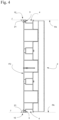
- the sealing member 10 consists of an elongated profile arranged to be mounted on or in a formwork panel 1, preferably along at least one of the edges of the formwork panel 1, 2 , as illustrated in the figure 2 , 3 And 4 . It comprises for this purpose a mounting zone 15 arranged to be received in a housing 3 provided in the formwork panel 1.
- the mounting zone 15 of the sealing member 10 and the corresponding housing 3 provided in the panel of sealing 1 have complementary shapes to be able to fit one inside the other. In addition, these shapes are symmetrical with respect to a median plane P, P' in order to be able to assemble the sealing member 10 to the mounting panel 1 both in one direction and in the other direction.
- the assembly zone 15 comprises a central part 16 delimited by a quadrilateral, extended by a T-shaped end part 17, delimiting two grooves 18 substantially in opposition.
- the mounting zone 15 of the sealing member 10 can have any other shape, the main thing being that it is adapted to that of the housing 3 provided in the formwork panel 1.
- the sealing member 10 also includes a joint zone 19 arranged to deform elastically and provide contact sealing at a joint plane J between the formwork panel 1 and another adjacent formwork panel (not shown ).
- This joint zone 19 extends the assembly zone 15 by a lip 20 positioned outside the formwork panel 1.
- the joint zone 19 extends perpendicularly to the median plane P of the assembly zone. 15 and parallel to the joint plane J, the lip 20 projecting on either side of the assembly zone 15.
- the sealing member 10 is characterized in that it further comprises a negative formwork zone 21 integrated into said elongated profile, and arranged to create an imprint in a molded construction element (not shown), such that including a cut angle.
- this negative formwork zone 21 is an integral part of the formwork panel 1, since it includes said sealing member 10, without the need to add or report in said formwork a chamfer or any other negative formwork profile.
- the negative formwork zone 21 is arranged substantially in the extension of the joint zone 19 and connected to it by the lip 20. It is also arranged adjacent to the assembly zone 15 and extends substantially parallel to it by means of a interval I. It presents with reference to the figure 1 a substantially triangular section with a flat base.
- This section more particularly corresponds to a right-angled isosceles triangle to create a flat-faced 45° chamfer in the corner of the molded construction element.
- the negative formwork zone 21 can of course have any other shape or section depending on the imprint to be made in the molded construction element. Certain variant embodiments are illustrated by way of example in the figures 5 to 8 , which will be detailed later.
- the joint zone 19 and the negative formwork zone 21 comprise a common face 22 arranged to deform elastically and ensure contact sealing at the joint plane J between two adjacent formwork panels.
- the common face 22 is mostly flat and smooth. It may end with an end zone 23 curved in the direction of the joint plane J. When the formwork is closed, this curved end zone 23 is compressed, retracts and aligns itself in the joint plane J. It promotes the pressing of the negative formwork zone 21 against the adjacent formwork panel, and thus allows the production of a clear and qualitative imprint in the molded construction element.
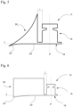
- FIG. 2 And 3 illustrate an example of a formwork panel 1 equipped with the sealing member 10 of the invention.
- This formwork panel 1 consists of a metal profile comprising a formwork face FC and two opposite bearing faces FA, at least one of which is intended to come into contact with another adjacent formwork panel via the zone of seal 19 of the sealing member 10.
- the formwork face FC is separated from each bearing face FA by a right angle.
- This example is of course not limiting given that the formwork face FC and at the at least one of the bearing faces FA can be separated by an angle between 0° and 180°, extreme values being excluded, depending on the construction element to be manufactured.
- the formwork panel 1 as shown corresponds to a wall or wall end formwork panel, used in a vertical direction, and intended to be held between two formwork panels by magnets (not shown) or any other adequate fixing device.
- the invention is of course not limited to this type of formwork panel, but extends to any other form of formwork panel, suitable for the construction element to be manufactured, such as, for example, a formwork panel for beams or slabs, used in a horizontal direction, in the factory or on site.
- the formwork panel 1 of the invention comprises in at least one of its bearing faces FA the housing 3 to receive the mounting zone 15 of a sealing member 10 according to the invention. It also comprises a cavity 4 adjacent to housing 3 and separated from said housing 3 by a wall 5 belonging to the profile. The cavity 4 makes it possible to receive the negative formwork zone 21 of the sealing member 10 when it is not in use.
- the housing 3 provided in the formwork panel 1 is delimited by two parallel walls 5 belonging to the section.
- the thickness of the wall 5 is at most equal to the interval I separating the assembly zone 15 and the negative formwork zone 21 from the sealing member 10.
- the housing 3 has a shape complementary to that of the mounting zone 15 of the sealing member 10 as mentioned above. It also has a symmetry with respect to a median plane P′ so as to be able to mount the sealing member 10 in the housing 3 in one or the other of the two mounting positions separated from each other by a 180° angle.
- the housing 3 comprises for this purpose an entry zone 6 delimited by a quadrilateral to accommodate the central part 16 of the assembly zone 15, followed by a bottom zone 7 separated from the entry zone 6 by two ribs 8 in opposition to accommodate the T-shaped end part 17 of the mounting zone 15.
- the housing 3 can have any other shape, the main thing being that it is complementary to that of the mounting zone 15 of the sealing member 10.
- the cavity 4 provided in the formwork panel 1 has an opening and a sufficient depth to accommodate the negative formwork zone 21 therein without constraining it, and this regardless of the shape of the zone negative formwork 21, 24, 25, 26 and 27, in accordance with the non-limiting examples illustrated in the figures 1 to 4 , 5 , 6 , 7 and 8 .
- the sealing member 10 is assembled to the formwork panel 1 preferably by a drawer-type sliding connection, the ribs 8 of the housing 3 forming with the grooves 18 of the mounting zone 15 of the slides.
- This sliding connection makes it possible to assemble the sealing member 10 to the formwork panel 1 by a movement of longitudinal translation from one end to the other of the formwork panel 1.
- the sealing member 10 is therefore mounted and easily disassembled so as to be able to modify its mounting position depending on whether or not it is desired to create an indentation or a broken angle in a molded construction element.
- the sealing member 10 thus combines two functions due to its reversibility: a sealing function alone in the first mounting position, and a sealing and impression function in the second mounting position.
- FIG 4 illustrates another formwork panel 2 for producing, for example, a post (not shown), this formwork panel 2 being able to be obtained by juxtaposition of two formwork panels 1.
- Four identical formwork panels 2 can be used, assembled in a square to delimit the section of the post to be manufactured.
- This formwork panel 2 has a greater longitudinal dimension than the formwork panel 1 of the figure 2 And 3 . It is equipped with two opposing sealing members 10 and mounted in the housings 3 provided for this purpose. They are mounted in the second mounting position making it possible to project the negative formwork zones 21 to create a chamfer in each corner of the post.
- each sealing member 10 can be easily dismantled, turned 180° and reassembled in the first position of assembly allowing the negative formwork zone 21 to be retracted into the cavity 4 provided for this purpose.
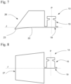
- the negative formwork zone 21 of the sealing member 10 can have different shapes and sections.
- the sealing member 11 comprises a negative formwork zone 24 having a substantially triangular section with a curved base, to create a 45° chamfer with a convex face in the corner of the molded construction element.
- the sealing member 12 comprises a negative formwork zone 25 having a substantially square or rectangular section, to create a square or rectangular recess in the corner of the molded construction element.
- the sealing member 13 comprises a negative formwork zone 26 having a substantially trapezoidal section, to create a trapezoidal recess in the corner of the molded construction element.
- the sealing member 14 comprises a negative formwork zone 27 symmetrical with respect to a plane of symmetry passing through the joint zone 19.
- This sealing member 14 makes it possible to produce a negative between two juxtaposed formwork panels 1, like the example shown in figure 4 , forming a groove on the formwork face FC to create a groove in the molded construction element.
- the hardness and density of the sealing member 10 to 14 give it sufficient rigidity to be able to be slid into the housing 3 of the formwork panel 1, 2 and to produce a sliding drawer connection allowing it to be easily reversible.
Landscapes
- Engineering & Computer Science (AREA)
- Mechanical Engineering (AREA)
- Manufacturing & Machinery (AREA)
- Chemical & Material Sciences (AREA)
- Ceramic Engineering (AREA)
- Architecture (AREA)
- Civil Engineering (AREA)
- Structural Engineering (AREA)
- Forms Removed On Construction Sites Or Auxiliary Members Thereof (AREA)
Applications Claiming Priority (1)
| Application Number | Priority Date | Filing Date | Title |
|---|---|---|---|
| FR2108687A FR3126133B1 (fr) | 2021-08-13 | 2021-08-13 | Organe d’étanchéité pour coffrage et panneau de coffrage équipé d’un tel organe d’étanchéité |
Publications (3)
| Publication Number | Publication Date |
|---|---|
| EP4134504A1 true EP4134504A1 (de) | 2023-02-15 |
| EP4134504B1 EP4134504B1 (de) | 2024-03-13 |
| EP4134504C0 EP4134504C0 (de) | 2024-03-13 |
Family
ID=77913277
Family Applications (1)
| Application Number | Title | Priority Date | Filing Date |
|---|---|---|---|
| EP22189457.9A Active EP4134504B1 (de) | 2021-08-13 | 2022-08-09 | Schalungsplatte mit einem dichtungselement |
Country Status (2)
| Country | Link |
|---|---|
| EP (1) | EP4134504B1 (de) |
| FR (1) | FR3126133B1 (de) |
Citations (3)
| Publication number | Priority date | Publication date | Assignee | Title |
|---|---|---|---|---|
| DE7310403U (de) | 1973-03-20 | 1973-07-19 | Mannesmann Leichtbau Gmbh | Fasenleiste |
| DE202004009596U1 (de) | 2004-06-17 | 2004-09-09 | Norz, Dieter | Dichtungs-Vorrichtung |
| WO2005116365A1 (en) | 2004-05-24 | 2005-12-08 | Srb Construction Technologies | Concrete sideform system |
-
2021
- 2021-08-13 FR FR2108687A patent/FR3126133B1/fr active Active
-
2022
- 2022-08-09 EP EP22189457.9A patent/EP4134504B1/de active Active
Patent Citations (3)
| Publication number | Priority date | Publication date | Assignee | Title |
|---|---|---|---|---|
| DE7310403U (de) | 1973-03-20 | 1973-07-19 | Mannesmann Leichtbau Gmbh | Fasenleiste |
| WO2005116365A1 (en) | 2004-05-24 | 2005-12-08 | Srb Construction Technologies | Concrete sideform system |
| DE202004009596U1 (de) | 2004-06-17 | 2004-09-09 | Norz, Dieter | Dichtungs-Vorrichtung |
Also Published As
| Publication number | Publication date |
|---|---|
| FR3126133A1 (fr) | 2023-02-17 |
| FR3126133B1 (fr) | 2023-12-22 |
| EP4134504B1 (de) | 2024-03-13 |
| EP4134504C0 (de) | 2024-03-13 |
Similar Documents
| Publication | Publication Date | Title |
|---|---|---|
| WO2009056775A2 (fr) | Ensemble d'un caisson de hayon et d'une piece destinee a etre rapportee sur le caisson | |
| EP3033463A1 (de) | Verkleidungsplatte | |
| EP4134504B1 (de) | Schalungsplatte mit einem dichtungselement | |
| FR2498666A1 (fr) | Dalles ou panneaux en un materiau deformable elastiquement, assemblables de facon etanche, notamment pour le revetement de sols ou de murs | |
| FR2813624A1 (fr) | Profile de raccord et d'etancheite, dispositif de raccord, panneau a structure sandwich, et ensemble de facade, de cloison ou de couverture | |
| FR2699576A1 (fr) | Eléments de cloison à briques de verre. | |
| FR2934194A1 (fr) | Procede de fabrication d'un element de vehicule, notamment d'une face avant technique | |
| FR2956135A1 (fr) | Dispositif d'isolation pour plancher a poutrelles | |
| FR2643099A1 (fr) | Bloc de construction a assemblage a sec et construction edifiee a l'aide de tels blocs | |
| FR2762041A1 (fr) | Portail a ossature metallique munie de profiles d'habillage | |
| WO2022008617A1 (fr) | Règle de maçon | |
| FR2672918A1 (fr) | Element d'encadrement de plaque; notamment pour la realisation de parois de batiment. | |
| EP0835387B1 (de) | Befestigungsvorrichtung zum verbinden der randstege von platten | |
| FR2989720A1 (fr) | Caisson tunnel de volet roulant | |
| FR3007785A1 (fr) | Chassis dormant pour ouverture de batiment | |
| FR2979367A1 (fr) | Mannequin pour la fabrication d'ouverture dans du beton coule | |
| WO2018060146A1 (fr) | Pièce de liaison intérieure pour structure sandwich et procédé d'assemblage correspondant | |
| EP3074641B1 (de) | Verbindung einer führung mit einer länglichen lippe in einem länglichen schlitz und anwendung auf eine verbindung einer luftführung mit einer düse | |
| EP1790786A1 (de) | Montierbare Gerüststruktur zum Aufbau eines Zeltgerüsts oder einer anderen Abdeckung in verschiedenen Formen | |
| EP4446516A1 (de) | Verbesserte vorrichtung zum verbinden von aneinanderliegenden und in der kante angeordneten platten oder platten an einer boden- oder wandabdeckung | |
| BE1023202B1 (fr) | Profilé dormant | |
| FR3128482A1 (fr) | élément préfabriqué d’appui ou de seuil amélioré | |
| FR2893962A1 (fr) | Panneau de construction, destine a constituer un element de paroi d'une structure constructible. | |
| CH711860A2 (fr) | Bouteille multi-usages. | |
| FR2964180A1 (fr) | Conduit de ventilation |
Legal Events
| Date | Code | Title | Description |
|---|---|---|---|
| PUAI | Public reference made under article 153(3) epc to a published international application that has entered the european phase |
Free format text: ORIGINAL CODE: 0009012 |
|
| STAA | Information on the status of an ep patent application or granted ep patent |
Free format text: STATUS: THE APPLICATION HAS BEEN PUBLISHED |
|
| AK | Designated contracting states |
Kind code of ref document: A1 Designated state(s): AL AT BE BG CH CY CZ DE DK EE ES FI FR GB GR HR HU IE IS IT LI LT LU LV MC MK MT NL NO PL PT RO RS SE SI SK SM TR |
|
| STAA | Information on the status of an ep patent application or granted ep patent |
Free format text: STATUS: REQUEST FOR EXAMINATION WAS MADE |
|
| 17P | Request for examination filed |
Effective date: 20230322 |
|
| RBV | Designated contracting states (corrected) |
Designated state(s): AL AT BE BG CH CY CZ DE DK EE ES FI FR GB GR HR HU IE IS IT LI LT LU LV MC MK MT NL NO PL PT RO RS SE SI SK SM TR |
|
| RIN1 | Information on inventor provided before grant (corrected) |
Inventor name: BECQUART, GUERRIC Inventor name: ALLIRAND, FREDERIC |
|
| GRAP | Despatch of communication of intention to grant a patent |
Free format text: ORIGINAL CODE: EPIDOSNIGR1 |
|
| STAA | Information on the status of an ep patent application or granted ep patent |
Free format text: STATUS: GRANT OF PATENT IS INTENDED |
|
| RIC1 | Information provided on ipc code assigned before grant |
Ipc: B28B 7/20 20060101ALI20231031BHEP Ipc: B28B 7/00 20060101ALI20231031BHEP Ipc: E04G 17/00 20060101AFI20231031BHEP |
|
| INTG | Intention to grant announced |
Effective date: 20231127 |
|
| GRAS | Grant fee paid |
Free format text: ORIGINAL CODE: EPIDOSNIGR3 |
|
| GRAA | (expected) grant |
Free format text: ORIGINAL CODE: 0009210 |
|
| STAA | Information on the status of an ep patent application or granted ep patent |
Free format text: STATUS: THE PATENT HAS BEEN GRANTED |
|
| AK | Designated contracting states |
Kind code of ref document: B1 Designated state(s): AL AT BE BG CH CY CZ DE DK EE ES FI FR GB GR HR HU IE IS IT LI LT LU LV MC MK MT NL NO PL PT RO RS SE SI SK SM TR |
|
| REG | Reference to a national code |
Ref country code: GB Ref legal event code: FG4D Free format text: NOT ENGLISH |
|
| REG | Reference to a national code |
Ref country code: CH Ref legal event code: EP |
|
| REG | Reference to a national code |
Ref country code: DE Ref legal event code: R096 Ref document number: 602022002345 Country of ref document: DE |
|
| REG | Reference to a national code |
Ref country code: IE Ref legal event code: FG4D Free format text: LANGUAGE OF EP DOCUMENT: FRENCH |
|
| U01 | Request for unitary effect filed |
Effective date: 20240313 |
|
| U07 | Unitary effect registered |
Designated state(s): AT BE BG DE DK EE FI FR IT LT LU LV MT NL PT SE SI Effective date: 20240319 |
|
| RAP4 | Party data changed (patent owner data changed or rights of a patent transferred) |
Owner name: LEVIAT |
|
| U1H | Name or address of the proprietor changed after the registration of the unitary effect |
Owner name: LEVIAT; FR |
|
| PG25 | Lapsed in a contracting state [announced via postgrant information from national office to epo] |
Ref country code: GR Free format text: LAPSE BECAUSE OF FAILURE TO SUBMIT A TRANSLATION OF THE DESCRIPTION OR TO PAY THE FEE WITHIN THE PRESCRIBED TIME-LIMIT Effective date: 20240614 |
|
| PG25 | Lapsed in a contracting state [announced via postgrant information from national office to epo] |
Ref country code: HR Free format text: LAPSE BECAUSE OF FAILURE TO SUBMIT A TRANSLATION OF THE DESCRIPTION OR TO PAY THE FEE WITHIN THE PRESCRIBED TIME-LIMIT Effective date: 20240313 Ref country code: RS Free format text: LAPSE BECAUSE OF FAILURE TO SUBMIT A TRANSLATION OF THE DESCRIPTION OR TO PAY THE FEE WITHIN THE PRESCRIBED TIME-LIMIT Effective date: 20240613 |
|
| PG25 | Lapsed in a contracting state [announced via postgrant information from national office to epo] |
Ref country code: ES Free format text: LAPSE BECAUSE OF FAILURE TO SUBMIT A TRANSLATION OF THE DESCRIPTION OR TO PAY THE FEE WITHIN THE PRESCRIBED TIME-LIMIT Effective date: 20240313 |
|
| PG25 | Lapsed in a contracting state [announced via postgrant information from national office to epo] |
Ref country code: RS Free format text: LAPSE BECAUSE OF FAILURE TO SUBMIT A TRANSLATION OF THE DESCRIPTION OR TO PAY THE FEE WITHIN THE PRESCRIBED TIME-LIMIT Effective date: 20240613 Ref country code: NO Free format text: LAPSE BECAUSE OF FAILURE TO SUBMIT A TRANSLATION OF THE DESCRIPTION OR TO PAY THE FEE WITHIN THE PRESCRIBED TIME-LIMIT Effective date: 20240613 Ref country code: HR Free format text: LAPSE BECAUSE OF FAILURE TO SUBMIT A TRANSLATION OF THE DESCRIPTION OR TO PAY THE FEE WITHIN THE PRESCRIBED TIME-LIMIT Effective date: 20240313 Ref country code: GR Free format text: LAPSE BECAUSE OF FAILURE TO SUBMIT A TRANSLATION OF THE DESCRIPTION OR TO PAY THE FEE WITHIN THE PRESCRIBED TIME-LIMIT Effective date: 20240614 Ref country code: ES Free format text: LAPSE BECAUSE OF FAILURE TO SUBMIT A TRANSLATION OF THE DESCRIPTION OR TO PAY THE FEE WITHIN THE PRESCRIBED TIME-LIMIT Effective date: 20240313 |
|
| U20 | Renewal fee for the european patent with unitary effect paid |
Year of fee payment: 3 Effective date: 20240827 |
|
| PG25 | Lapsed in a contracting state [announced via postgrant information from national office to epo] |
Ref country code: IS Free format text: LAPSE BECAUSE OF FAILURE TO SUBMIT A TRANSLATION OF THE DESCRIPTION OR TO PAY THE FEE WITHIN THE PRESCRIBED TIME-LIMIT Effective date: 20240713 |
|
| PG25 | Lapsed in a contracting state [announced via postgrant information from national office to epo] |
Ref country code: SM Free format text: LAPSE BECAUSE OF FAILURE TO SUBMIT A TRANSLATION OF THE DESCRIPTION OR TO PAY THE FEE WITHIN THE PRESCRIBED TIME-LIMIT Effective date: 20240313 |
|
| PG25 | Lapsed in a contracting state [announced via postgrant information from national office to epo] |
Ref country code: CZ Free format text: LAPSE BECAUSE OF FAILURE TO SUBMIT A TRANSLATION OF THE DESCRIPTION OR TO PAY THE FEE WITHIN THE PRESCRIBED TIME-LIMIT Effective date: 20240313 |
|
| PG25 | Lapsed in a contracting state [announced via postgrant information from national office to epo] |
Ref country code: PL Free format text: LAPSE BECAUSE OF FAILURE TO SUBMIT A TRANSLATION OF THE DESCRIPTION OR TO PAY THE FEE WITHIN THE PRESCRIBED TIME-LIMIT Effective date: 20240313 |
|
| PG25 | Lapsed in a contracting state [announced via postgrant information from national office to epo] |
Ref country code: SK Free format text: LAPSE BECAUSE OF FAILURE TO SUBMIT A TRANSLATION OF THE DESCRIPTION OR TO PAY THE FEE WITHIN THE PRESCRIBED TIME-LIMIT Effective date: 20240313 |
|
| PG25 | Lapsed in a contracting state [announced via postgrant information from national office to epo] |
Ref country code: SM Free format text: LAPSE BECAUSE OF FAILURE TO SUBMIT A TRANSLATION OF THE DESCRIPTION OR TO PAY THE FEE WITHIN THE PRESCRIBED TIME-LIMIT Effective date: 20240313 Ref country code: SK Free format text: LAPSE BECAUSE OF FAILURE TO SUBMIT A TRANSLATION OF THE DESCRIPTION OR TO PAY THE FEE WITHIN THE PRESCRIBED TIME-LIMIT Effective date: 20240313 Ref country code: RO Free format text: LAPSE BECAUSE OF FAILURE TO SUBMIT A TRANSLATION OF THE DESCRIPTION OR TO PAY THE FEE WITHIN THE PRESCRIBED TIME-LIMIT Effective date: 20240313 Ref country code: PL Free format text: LAPSE BECAUSE OF FAILURE TO SUBMIT A TRANSLATION OF THE DESCRIPTION OR TO PAY THE FEE WITHIN THE PRESCRIBED TIME-LIMIT Effective date: 20240313 Ref country code: IS Free format text: LAPSE BECAUSE OF FAILURE TO SUBMIT A TRANSLATION OF THE DESCRIPTION OR TO PAY THE FEE WITHIN THE PRESCRIBED TIME-LIMIT Effective date: 20240713 Ref country code: CZ Free format text: LAPSE BECAUSE OF FAILURE TO SUBMIT A TRANSLATION OF THE DESCRIPTION OR TO PAY THE FEE WITHIN THE PRESCRIBED TIME-LIMIT Effective date: 20240313 |
|
| REG | Reference to a national code |
Ref country code: DE Ref legal event code: R097 Ref document number: 602022002345 Country of ref document: DE |
|
| PLBE | No opposition filed within time limit |
Free format text: ORIGINAL CODE: 0009261 |
|
| STAA | Information on the status of an ep patent application or granted ep patent |
Free format text: STATUS: NO OPPOSITION FILED WITHIN TIME LIMIT |
|
| 26N | No opposition filed |
Effective date: 20241216 |
|
| PG25 | Lapsed in a contracting state [announced via postgrant information from national office to epo] |
Ref country code: MC Free format text: LAPSE BECAUSE OF FAILURE TO SUBMIT A TRANSLATION OF THE DESCRIPTION OR TO PAY THE FEE WITHIN THE PRESCRIBED TIME-LIMIT Effective date: 20240313 |
|
| PG25 | Lapsed in a contracting state [announced via postgrant information from national office to epo] |
Ref country code: IE Free format text: LAPSE BECAUSE OF NON-PAYMENT OF DUE FEES Effective date: 20240809 |
|
| U20 | Renewal fee for the european patent with unitary effect paid |
Year of fee payment: 4 Effective date: 20250825 |
|
| PG25 | Lapsed in a contracting state [announced via postgrant information from national office to epo] |
Ref country code: CY Free format text: LAPSE BECAUSE OF FAILURE TO SUBMIT A TRANSLATION OF THE DESCRIPTION OR TO PAY THE FEE WITHIN THE PRESCRIBED TIME-LIMIT; INVALID AB INITIO Effective date: 20220809 |
|
| PG25 | Lapsed in a contracting state [announced via postgrant information from national office to epo] |
Ref country code: HU Free format text: LAPSE BECAUSE OF FAILURE TO SUBMIT A TRANSLATION OF THE DESCRIPTION OR TO PAY THE FEE WITHIN THE PRESCRIBED TIME-LIMIT; INVALID AB INITIO Effective date: 20220809 |
|
| REG | Reference to a national code |
Ref country code: CH Ref legal event code: H13 Free format text: ST27 STATUS EVENT CODE: U-0-0-H10-H13 (AS PROVIDED BY THE NATIONAL OFFICE) Effective date: 20260324 |
|
| PG25 | Lapsed in a contracting state [announced via postgrant information from national office to epo] |
Ref country code: CH Free format text: LAPSE BECAUSE OF NON-PAYMENT OF DUE FEES Effective date: 20250831 |