EP4134511B1 - Store à lamelles - Google Patents
Store à lamelles Download PDFInfo
- Publication number
- EP4134511B1 EP4134511B1 EP21190861.1A EP21190861A EP4134511B1 EP 4134511 B1 EP4134511 B1 EP 4134511B1 EP 21190861 A EP21190861 A EP 21190861A EP 4134511 B1 EP4134511 B1 EP 4134511B1
- Authority
- EP
- European Patent Office
- Prior art keywords
- rail
- guides
- guide
- inclination
- devices
- Prior art date
- Legal status (The legal status is an assumption and is not a legal conclusion. Google has not performed a legal analysis and makes no representation as to the accuracy of the status listed.)
- Active
Links
Images





Classifications
-
- E—FIXED CONSTRUCTIONS
- E06—DOORS, WINDOWS, SHUTTERS, OR ROLLER BLINDS IN GENERAL; LADDERS
- E06B—FIXED OR MOVABLE CLOSURES FOR OPENINGS IN BUILDINGS, VEHICLES, FENCES OR LIKE ENCLOSURES IN GENERAL, e.g. DOORS, WINDOWS, BLINDS, GATES
- E06B9/00—Screening or protective devices for wall or similar openings, with or without operating or securing mechanisms; Closures of similar construction
- E06B9/24—Screens or other constructions affording protection against light, especially against sunshine; Similar screens for privacy or appearance; Slat blinds
- E06B9/26—Lamellar or like blinds, e.g. venetian blinds
- E06B9/28—Lamellar or like blinds, e.g. venetian blinds with horizontal lamellae, e.g. non-liftable
- E06B9/30—Lamellar or like blinds, e.g. venetian blinds with horizontal lamellae, e.g. non-liftable liftable
- E06B9/302—Lamellar or like blinds, e.g. venetian blinds with horizontal lamellae, e.g. non-liftable liftable without ladder-tape, e.g. with lazy-tongs, with screw spindle
-
- E—FIXED CONSTRUCTIONS
- E06—DOORS, WINDOWS, SHUTTERS, OR ROLLER BLINDS IN GENERAL; LADDERS
- E06B—FIXED OR MOVABLE CLOSURES FOR OPENINGS IN BUILDINGS, VEHICLES, FENCES OR LIKE ENCLOSURES IN GENERAL, e.g. DOORS, WINDOWS, BLINDS, GATES
- E06B9/00—Screening or protective devices for wall or similar openings, with or without operating or securing mechanisms; Closures of similar construction
- E06B9/24—Screens or other constructions affording protection against light, especially against sunshine; Similar screens for privacy or appearance; Slat blinds
- E06B9/26—Lamellar or like blinds, e.g. venetian blinds
- E06B9/28—Lamellar or like blinds, e.g. venetian blinds with horizontal lamellae, e.g. non-liftable
- E06B9/30—Lamellar or like blinds, e.g. venetian blinds with horizontal lamellae, e.g. non-liftable liftable
- E06B9/32—Operating, guiding, or securing devices therefor
- E06B9/322—Details of operating devices, e.g. pulleys, brakes, spring drums, drives
-
- E—FIXED CONSTRUCTIONS
- E06—DOORS, WINDOWS, SHUTTERS, OR ROLLER BLINDS IN GENERAL; LADDERS
- E06B—FIXED OR MOVABLE CLOSURES FOR OPENINGS IN BUILDINGS, VEHICLES, FENCES OR LIKE ENCLOSURES IN GENERAL, e.g. DOORS, WINDOWS, BLINDS, GATES
- E06B9/00—Screening or protective devices for wall or similar openings, with or without operating or securing mechanisms; Closures of similar construction
- E06B9/24—Screens or other constructions affording protection against light, especially against sunshine; Similar screens for privacy or appearance; Slat blinds
- E06B9/26—Lamellar or like blinds, e.g. venetian blinds
- E06B9/28—Lamellar or like blinds, e.g. venetian blinds with horizontal lamellae, e.g. non-liftable
- E06B9/30—Lamellar or like blinds, e.g. venetian blinds with horizontal lamellae, e.g. non-liftable liftable
- E06B9/32—Operating, guiding, or securing devices therefor
- E06B9/325—Immobilising devices preventing raising
-
- E—FIXED CONSTRUCTIONS
- E06—DOORS, WINDOWS, SHUTTERS, OR ROLLER BLINDS IN GENERAL; LADDERS
- E06B—FIXED OR MOVABLE CLOSURES FOR OPENINGS IN BUILDINGS, VEHICLES, FENCES OR LIKE ENCLOSURES IN GENERAL, e.g. DOORS, WINDOWS, BLINDS, GATES
- E06B9/00—Screening or protective devices for wall or similar openings, with or without operating or securing mechanisms; Closures of similar construction
- E06B9/24—Screens or other constructions affording protection against light, especially against sunshine; Similar screens for privacy or appearance; Slat blinds
- E06B9/26—Lamellar or like blinds, e.g. venetian blinds
- E06B9/28—Lamellar or like blinds, e.g. venetian blinds with horizontal lamellae, e.g. non-liftable
- E06B9/30—Lamellar or like blinds, e.g. venetian blinds with horizontal lamellae, e.g. non-liftable liftable
- E06B9/32—Operating, guiding, or securing devices therefor
- E06B9/327—Guides for raisable lamellar blinds with horizontal lamellae
-
- E—FIXED CONSTRUCTIONS
- E06—DOORS, WINDOWS, SHUTTERS, OR ROLLER BLINDS IN GENERAL; LADDERS
- E06B—FIXED OR MOVABLE CLOSURES FOR OPENINGS IN BUILDINGS, VEHICLES, FENCES OR LIKE ENCLOSURES IN GENERAL, e.g. DOORS, WINDOWS, BLINDS, GATES
- E06B9/00—Screening or protective devices for wall or similar openings, with or without operating or securing mechanisms; Closures of similar construction
- E06B9/24—Screens or other constructions affording protection against light, especially against sunshine; Similar screens for privacy or appearance; Slat blinds
- E06B9/26—Lamellar or like blinds, e.g. venetian blinds
- E06B9/38—Other details
- E06B9/388—Details of bottom or upper slats or their attachment
-
- E—FIXED CONSTRUCTIONS
- E06—DOORS, WINDOWS, SHUTTERS, OR ROLLER BLINDS IN GENERAL; LADDERS
- E06B—FIXED OR MOVABLE CLOSURES FOR OPENINGS IN BUILDINGS, VEHICLES, FENCES OR LIKE ENCLOSURES IN GENERAL, e.g. DOORS, WINDOWS, BLINDS, GATES
- E06B9/00—Screening or protective devices for wall or similar openings, with or without operating or securing mechanisms; Closures of similar construction
- E06B9/24—Screens or other constructions affording protection against light, especially against sunshine; Similar screens for privacy or appearance; Slat blinds
- E06B9/26—Lamellar or like blinds, e.g. venetian blinds
- E06B9/28—Lamellar or like blinds, e.g. venetian blinds with horizontal lamellae, e.g. non-liftable
- E06B9/30—Lamellar or like blinds, e.g. venetian blinds with horizontal lamellae, e.g. non-liftable liftable
- E06B9/32—Operating, guiding, or securing devices therefor
- E06B9/322—Details of operating devices, e.g. pulleys, brakes, spring drums, drives
- E06B2009/3222—Cordless, i.e. user interface without cords
Definitions
- the invention relates to a slatted blind according to the preamble of claim 1.
- the slatted blind is a blind with movable slats for sun and weather protection as well as privacy and, if necessary, security.
- the slatted blind is also referred to as the Raffstore or the slatted blind.
- Slatted blinds with side guides, slats and an end rail are used to close and open building openings such as windows and doors.
- the end rail is lowered and raised using lifting straps, for example.
- the inclination of the slats is adjusted using adjusting cords, for example, whereby the adjusting cords are attached to the edges of the slats on both sides of the longitudinal axis of the slats.
- Slatted blinds enable the complete opening, covering of an upper area and the complete covering of building openings by positioning the end rail arranged under the slats accordingly.
- the inclination of the slats can be adjusted to a horizontal level.
- the same drive device is used for adjusting the slat inclination.
- EP 1 213 437 A2 describes slatted blinds that can expose an upper area of the building opening while covering the remaining lower area.
- a slatted blind comprises a top rail, slats, an end rail, two guides and two drive devices arranged on the guides for moving the top rail or the end rail and for adjusting the inclination of the top rail.
- the guides and the drive devices When installed, the guides and the drive devices extend over a height range at the opposite longitudinal ends of the top rail and the end rail.
- the drive devices comprise closed chains with two support elements each running around an upper and a lower deflection device.
- the support elements make two top rail brackets with the top rail arranged therebetween displaceable between an upper and a lower top rail end position or end rail brackets with the end rail arranged therebetween displaceable between an upper and a lower end rail end position along the guides, wherein the end rail is at the lower end rail end position when the top rail is moved and the top rail is at the upper top rail end position when the end rail is moved.
- the solution according to EP 1 213 437 A2 The inclination of the slats that are not stacked on the end rail can be adjusted by adjusting the inclination of the top rail. To do this, adjusting cords on both sides of the longitudinal axis of the top rail lead from the top rail edges to the corresponding slat edges that are attached to the adjusting cords at equal intervals.
- the solution according to EP 1 213 437 A2 The inclination of the slats cannot be set to any desired angle.
- an inclination of around 45° to the horizontal plane is specified so that the slats can be placed without interference on the end rail positioned at the lower end rail end position or on the slats lying on it when lowered.
- the top rail moves upwards, the slats are in the open position with an inclination of around 0°.
- the object of the invention is to find a solution in which the slats above the stack on the end rail can be adjusted between an open orientation that deviates only slightly from the horizontal orientation and a substantially vertical or closed orientation when the top rail is positioned below the upper top rail end position.
- the upper rail brackets which hold the upper rail and move it along the guides, must enable a change in function from the movement of the upper rail to the adjustment of the inclination of the upper rail or vice versa at any position between an upper and a lower upper rail end position.
- a reversal of the direction of movement of the Drive devices or their supporting elements that support the top rail brackets do not move the top rail along the guides in the opposite direction, but rather the inclination of the top rail is adjusted.
- the top rail should only be moved after the inclination of the top rail has been adjusted to a predetermined closed or open state.
- the change in function when changing the direction of movement of the support elements can be achieved if the upper rail holders comprise inclination adjustment devices with clamping devices.
- the clamping devices can be clamped to the guides to adjust the inclination of the upper rail and can be moved along the guides to move the upper rail.
- the two states “clampable” and “movable” are achieved with a device that can apply and release a braking force or a holding force between the upper rail holders and the guides.
- the clamping devices can be designed as braking devices or, if necessary, as latching devices and the clamping thus comprises frictional contacts and engagement contacts.
- the end of the adjustment of the inclination is signalled by a movement of the supporting elements according to a predetermined
- the adjustment of the clamping devices and the associated release of the clamping on the guides are achieved by the movement distance. After the clamping is released, the further movement of the support elements causes a movement of the top rail brackets and thus of the top rail along the guides.
- both top rail holders comprise guide parts that are slidably guided on the guides and on which the clamping devices of the inclination adjustment devices are arranged so that they can move between two end positions.
- the support elements move the guide parts along the guides and the clamping devices that are movably arranged on the guide parts cannot be moved along with them, but remain at the clamping points on the guides.
- the clamping devices remain in the positions of the guides determined by the clamping until the guide elements are moved relative to the clamped clamping devices to such an extent that the further movement of the guide elements results in an adjustment of the clamping devices.
- This adjustment causes the clamping on the guides to be released and a movement the guide parts together with the clamping devices along the guides.
- the clamping devices are designed in such a way that the described function change can be achieved for both directions of movement of the top rail brackets and for both pivoting directions of the inclination adjustment.
- the clamping and the displaceability of the clamping devices on the guides depends on the position of the clamping devices relative to the guide parts. If the clamping devices are positioned in a range between two end positions on the guide parts that limit the range of relative movement, the clamping is set and if the clamping devices are positioned at one of the two end positions on the guide parts, the displaceability is set.
- the clamping devices each comprise a base plate on the guide part that can be moved in the direction of the associated guide and two movable clamping elements on the base plate.
- the two movable clamping elements are pre-tensioned to clamp onto the associated guide for one of the two directions of movement of the guide.
- the clamping elements can be used as braking elements or, if necessary, are designed as snap-in elements and the clamping thus includes friction contacts or engagement contacts with the associated guide.
- the movable clamping elements can be adjusted against the preload by a release device on the guide part to release the clamping.
- the base plate with the guide part can be moved by the support element along the guide.
- the two end positions of the clamping devices or base plates on the guide parts define the maximum range of relative movement.
- the relative movement between the guide part and the base plate can be used to adjust the inclination of the top rail.
- the guide parts comprise inclination adjusters connected to the top rail, which are movably mounted on the guide parts and are adjustable via a coupling according to the relative position between the guide part and the base plate on the guide parts. With this adjustability, the inclination of the top rail can be set as desired from completely open to completely closed. As soon as the desired inclination is reached when adjusting the inclination, the movements of the support elements and the guide parts moved with them are stopped.
- the coupling transfers the relative movement between the guide parts and the base plates guided on them into a movement of the inclination adjusters.
- the coupling on the clamping devices in particular on the base plate, comprises curved guides and the inclination adjusters can be rotated about an axis of rotation running parallel to the longitudinal axis of the top rail.
- the couplings also comprise swivel arms that are firmly connected to the inclination adjusters and are guided on the curved guide with a guide engagement spaced from the axis of rotation.
- the relative movement between the guide parts and the base plates guided on them leads to a movement of the guide engagements along the curved guides.
- the swivel arms, the curved guides and the end positions of the Base plates on the guide parts are designed relative to the position of the rotation axis of the tilt adjuster so that the rotational movement of the tilt adjuster required for tilt adjustment between open and closed can be achieved.
- the support elements on the top rail brackets engage in holding arms that are movably attached to the swivel arms of the couplings.
- the holding arms have receptacles at their free ends for receiving the support elements. So that the holding arms can be hooked onto supports at the upper ends of the guides, the holding arms have hooking elements at the free ends.
- the support elements are arranged on the closed drive elements that run around an upper and a lower deflection device.
- the support elements move the holding arms of the upper rail brackets held on them in accordance with the movement of the drive elements up to the upper deflection device, around which they move and slightly downwards, the holding arms are hooked onto the supports of the guides with the hooking elements at the end of this movement.
- the drive elements move further, the support elements are moved downwards and emerge from the holders on the holding arms.
- the upper rail remains at the upper end of the guides.
- the clamping devices are clamped to the guides and the inclination adjustment devices adjust the inclination of the top rail.
- the position of the supports relative to the upper deflection devices is selected so that the inclination adjustment devices align the top rail with a predetermined inclination when the top rail brackets move downwards leading to the hooking. This predetermined inclination of the top rail corresponds to a desired working position of the slats when the end rail moves.
- the holding arms are provided with anti-release devices which prevent the support elements from coming out of the holders when the upper rail is lifted manually.
- the devices include, for example, safety plates which only allow the support elements to be removed from the holders when the upper deflection device is used.
- the support elements for moving the end rail are arranged opposite the support elements for moving the upper rail on the closed drive elements. If the support elements for moving the upper rail are at the upper deflection device, the end rail is at the lower end rail end position and the support elements for moving the end rail are at the lower deflection device.
- the support elements for the end rail engage in the end rail brackets and move the end rail upwards along the guides. If the direction of movement of the drive elements is changed when the end rail is raised, the end rail moves downwards.
- the upper rail does not change its inclination and the slats are in the working position as long as the end rail is above the lower end rail end position or as long as the upper rail is held by the support arms on the supports.
- the end rail brackets comprise guide areas guided on the guides and end rail supports connected to the end rails.
- one advantageous embodiment uses anti-impact devices.
- the anti-impact devices prevent the end rail from being pushed upwards by hand.
- the end rail supports are positioned at the guide areas in the direction of the Guides are held so that they can move between a lower and an upper stop.
- the high-impact protection is activated.
- the end rail brackets or the guide areas are moved upwards by the support elements, the end rail supports are at the lower stop, the high-impact protection is deactivated and the end rail is moved with the end rail brackets moved upwards from the lower end rail end position towards the upper end rail end position.
- An advantageous anti-lifting device comprises at least one spring element on each of the end rail brackets.
- the spring elements When the end rail support is in a position spaced from the lower stop, the spring elements are deflected from the deflection areas of the guide areas from release positions to engagement positions. In the engagement positions, when an attempt is made to push up, the spring elements engage in securing elements that are firmly connected to the guides, which prevents further pushing up. In the release positions, the support elements can move the end rail brackets upwards because the spring elements do not engage in the securing elements.
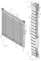
- the Figures 1 to 6 show a slatted blind 1 in different application positions.
- an upper area of a building opening is released and the remaining lower area is covered.
- the use position according to the Figures 3 and 4 The entire building opening is covered.
- an upper area of a building opening is covered and the remaining lower area is exposed.
- the slatted blind 1 comprises a top rail 2, slats 3, an end rail 4, two guides 5 and two drive devices 6 arranged on the guides 5 for moving the top rail 2 or the end rail 4 and for adjusting the inclination of the top rail 2.
- the guides 5 and the drive devices 6 extend over a height range at the opposite longitudinal ends of the top rail 2 and the end rail 4.
- the drive devices 6 each comprise closed drive elements 9, for example chains, running around an upper and a lower deflection device 7 or 8, each with two support elements 10.
- the two guides 5 are connected at the upper end with a connecting profile V.
- a drive motor for driving the two drive devices 6 and a shaft which drives the drive elements 9 in the two upper deflection devices 7. It goes without saying that the shaft can also be driven by a manually operated crank.
- the support elements 10 make two top rail brackets 11 with the top rail 2 arranged therebetween displaceable between an upper and a lower top rail end position or end rail brackets 12 with the end rail 4 arranged therebetween displaceable between an upper and a lower end rail end position along the guides 5, wherein the end rail 4 is at the lower end rail end position when the top rail 2 is moved and the top rail 2 is at the upper top rail end position when the end rail 4 is moved.
- the upper rail holders 11 comprise inclination adjustment devices 13, which make the inclination of the upper rail 2 adjustable when the upper rail 2 is in a position spaced from the upper upper rail end position and when the drive devices 6 are moved, wherein the inclination adjustment devices 13 comprise clamping devices 14, which can be clamped to the guides 5 for adjusting the inclination of the upper rail 2 and can be displaced along the guides 5 for moving the upper rail 2.
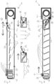
- FIG. 7 shows that the support elements 10 for moving the end rail 4 are opposite the support elements 10 for moving the upper rail 2 at the closed drive elements 9 are arranged.
- Fig. 7 shows the upper rail 2 slightly below the upper deflection device 7.
- Holding arms 15 with receptacles 16 formed at their free ends are suspended on the support elements 10.
- the holding arms 15 are movably attached to the upper rail brackets 11.
- Fig. 7 shows that the slats 3 are closed when the top rail 2 changes to the upward movement and are opened when the top rail 2 changes to the downward movement.
- a desired inclination of the slats 3 is set by stopping the movement of the top rail 2 at the desired inclination. During the sustained downward movement the slats 3 are open and during the sustained upward movement they are closed.
- the inclination of the upper rail 2 is transmitted via adjusting cords S to the slats 3, which do not belong to the stack on the end rail 4.
- the adjusting cords S lead on both sides of the longitudinal axis of the upper rail 2 from the upper rail edges to the corresponding slat edges attached to the adjusting cords at equal intervals.
- the holding arms 15 of the upper rail brackets 11 held thereon over the upper deflection devices 7 are hooked with their arm ends 17 onto supports 18 of the guides 5 (cf. Fig. 8 ).
- the clamping devices 14 are clamped to the guides 5 and the top rail 2 is aligned with a predetermined inclination by the inclination adjustment devices 13. This predetermined inclination of the top rail 2, which corresponds to the length of the downward movement, corresponds to the desired working position of the slats 3 when the end rail 4 is moved.
- Fig. 8 shows that the support elements 10 for moving the end rail 4 are at the lower deflection device 8 when the support elements 10 for moving the upper rail 2 are at the upper deflection device 7. With a further movement of the drive elements 9 in the same In the direction of rotation, the end rail 4 is moved upwards by the holding elements 10 engaging in the end rail brackets 12.
- the upper rail holders 11 move slightly upwards at the upper deflection devices 7.
- the clamping devices 14 can clamp onto the guides 5 and the upper rail 2 is moved into the closed positions by the inclination adjustment device 13. After the transition over the upper deflection devices 7, the upper rail holders 11 are moved downwards, the clamping holders 14 are clamped onto the guides 5 and the inclination adjustment devices 13 bring the upper rail 2 into the open position.
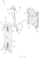
- Fig. 9 to 16 show the details and functionality of the upper rail holders 11 of an advantageous embodiment.
- the upper rail holders 11 comprise guide parts 19, which are slidably guided on the guides 5.
- the clamping devices 14 of the inclination adjustment devices 13 are arranged on the guide parts 19 so that they can move between two end positions. When the clamping devices 14 are clamped to the guides 5, the support elements 10 move the guide parts 19 along the guides 5 and the clamping devices 14 movably arranged on the guide parts 19 cannot be moved along with them, but remain at the clamping points on the guides 5.
- the clamping devices 14 remain in the positions of the guides 5 determined by the clamping until the guide elements 19 are moved relative to the clamped clamping devices 14 to such an extent that the further movement of the guide elements 19 achieves an adjustment of the clamping devices 14. This adjustment causes the clamping on the guides 5 to be released and a movement of the guide parts 19 together with the clamping devices 14 along the guides 5.
- the clamping devices 14 are designed so that the described function change for both
- the clamping devices 14 each comprise a base plate 20 which can be moved on the guide part 19 in the direction of the associated guide 5 and two movable clamping elements 21 on the base plate 20, which can preferably be pivoted about pivot axes.
- the two movable clamping elements 21 are pre-tensioned with a spring 22 for clamping to the associated guide 5 for one of the two directions of movement of the guide 5.
- a guide 5 according to Fig. 13 For example, it comprises a web 23 which, according to Fig. 14 between two clamping projections 24 of the clamping elements 21.
- the movable clamping elements 21 are connected to a release device 25 of the guide part 19 to release the clamping adjustable against the preload.
- the base plate 20 with the guide part 19 can be moved by the support element 10 along the guide 5.
- the two end positions of the clamping devices 14 or base plates 20 on the guide parts 19 determine the maximum range of the relative movement.
- the guide parts 19 comprise inclination adjusters 26 connected to the upper rail 2, which are movably mounted on the guide parts 19 and can be adjusted via a coupling according to the relative position between the guide part 19 and the base plate 20 on the guide parts 19.
- the inclination of the upper rail 2 can be set as desired from completely open to completely closed. As soon as the desired inclination is reached when adjusting the inclination, the movements of the support elements 10 and the guide parts 19 moved with them are stopped.
- the coupling transfers the relative movement between the guide parts 19 and the base plates 20 guided thereon into a movement of the inclination adjusters.
- the coupling on the base plates comprises curved guides 27 and the inclination adjusters 26 can be rotated about an axis of rotation running parallel to the longitudinal axis of the upper rail 2.
- the couplings also comprise swivel arms 28 which are firmly connected to the inclination adjusters 26 and are guided on the curved guide 27 with a guide engagement 29 spaced from the axis of rotation.
- the relative movement between the guide parts 19 and the base plates 20 guided thereon leads to a movement of the guide engagements 29 along the curved guides 27.
- the pivot arms 28, the curved guides 27 and the end positions of the base plates 20 on the guide parts 19 are designed relative to the position of the axis of rotation of the inclination adjusters 26 such that the rotational movement of the inclination adjusters 26 required for the inclination adjustment between open and closed can be achieved.
- the support elements 10 engage in the upper rail brackets 11 in the holding arms 15, which are movably attached to the swivel arms 28 of the couplings.
- the holding arms 15 comprise their free ends have receptacles 16 for receiving the support elements 10. So that the holding arms 15 can be hooked onto supports 18 at the upper ends of the guides 5, these include hooking elements 30 at the free ends.
- Fig. 17 to 19 show advantageous end rail holders 12 with a guide area 31 guided on the guides 5 and with an end rail support 32 connected to an end rail 4. So that the end rail support 32 can only be moved upwards by a support element 10 or by a drive element 9, the embodiment shown includes a push-up safety device.
- the push-up safety device prevents the end rail 4 from being pushed upwards by hand.
- the high impact protection is achieved by the end rail support 32 being held so that it can move on the guide area 31 in the direction of the guides 5 between a lower and an upper stop.
- the high impact protection is activated.
- the end rail holder 32 or the guide area 31 is moved upwards by a support element 10
- the end rail support 32 is at the lower stop, the high impact protection is deactivated and the end rail 4 is moved upwards with the end rail holder 32. from the lower end rail end position towards the upper end rail end position.
- the end rail holder 12 comprises at least one spring element 33.
- the spring elements 33 are deflected from the release position into the engagement position by deflection areas 34 of the guide areas 31.
- engagement areas 35 of the spring elements 33 engage in securing elements 36 that are firmly connected to the guides 5, which prevents further pushing up.
- release position the support elements 10 can move the end rail holders 12 upwards because the spring elements 33 do not engage in the securing elements 36.
- the holding arms 15 are provided with anti-release devices 37 which prevent the support elements 10 from coming out of the receptacles 16 when the upper rail 2 is lifted manually.
- the anti-release devices 37 comprise, for example, securing plates which only allow the support elements to be removed from the receptacles at the upper deflection device 7.
Landscapes
- Engineering & Computer Science (AREA)
- Structural Engineering (AREA)
- Architecture (AREA)
- Civil Engineering (AREA)
- Blinds (AREA)
Claims (10)
- Store à lamelles (1) pour ouvertures de bâtiment, avec un rail supérieur (2), deux supports de rail supérieur (11), des lamelles (3), un rail d'extrémité (4), deux supports de rail d'extrémité (12), deux guides (5) et, pour chaque guide (5), avec un dispositif d'entraînement (6) pour déplacer le rail supérieur (2) ou le rail d'extrémité (4) et pour régler l'inclinaison du rail supérieur (2) et, en conséquence, d'au moins une des lamelles (3), les guides (5) et les dispositifs d'entraînement (6) s'étendant, à l'état monté, sur une plage de hauteurs aux extrémités longitudinales détournées l'une de l'autre du rail supérieur (2) ainsi que du rail d'extrémité (4), et les dispositifs d'entraînement (6) comprenant chacun des éléments d'entraînement (9) avec chacun deux éléments porteurs (10), circulant autour d'un dispositif de renvoi supérieur et d'un dispositif de renvoi inférieur (7, 8), lesquels éléments porteurs (10) rendant aptes à coulisser les supports de rail supérieur (11) avec le rail supérieur (2) agencé entre eux entre une position d'extrémité supérieure et une position d'extrémité inférieure du rail supérieur ou les supports de rail d'extrémité (12) avec le rail d'extrémité (4) agencé entre eux entre une position d'extrémité supérieure et une position d'extrémité inférieure du rail d'extrémité le long des guides (5), le rail d'extrémité (4) étant à la position d'extrémité inférieure du rail d'extrémité lorsque le rail supérieur (2) est déplacé, et le rail supérieur (2) étant à la position d'extrémité supérieure du rail supérieur lorsque le rail d'extrémité (4) est déplacé, les supports de rail supérieur (11) comprenant des dispositifs de réglage d'inclinaison (13), qui, dans des positions du rail supérieur (2) espacées de la position d'extrémité supérieure du rail supérieur et lors d'un déplacement des dispositifs d'entraînement (6), rendent réglable l'inclinaison du rail supérieur (2), caractérisé en ce que les dispositifs de réglage d'inclinaison (13) comprennent des appareils de serrage (14), qui peuvent être bloqués par serrage sur les guides (5) pour le réglage de l'inclinaison du rail supérieur (2) et qui sont aptes à coulisser le long des guides (5) pour le déplacement du rail supérieur (2).
- Store à lamelles (1) selon la revendication 1, caractérisé en ce que les deux supports de rail supérieur (11) comprennent des parties de guidage (19) qui sont guidées de manière apte à coulisser sur les guides (5) et sur lesquelles les appareils de serrage (14) des dispositifs de réglage d'inclinaison (13) sont agencés de manière mobile entre deux positions d'extrémité.
- Store à lamelles (1) selon la revendication 2, caractérisé en ce que le blocage par serrage et l'aptitude à coulisser des appareils de serrage (14) sur les guides (5) sont ajustables en fonction de la position des appareils de serrage (14) par rapport aux parties de guidage (19) : lorsque les appareils de serrage (14) sont positionnés dans une zone entre les deux positions d'extrémité sur les parties de guidage (19), le blocage par serrage est ajusté et, lorsque les appareils de serrage (14) sont positionnés dans l'une des deux positions d'extrémité sur les parties de guidage (19), l'aptitude à coulisser est ajustée.
- Store à lamelles selon la revendication 3, caractérisé en ce que les appareils de serrage (14) comprennent une plaque de base (20) apte à coulisser sur la partie de guidage (19) en direction du guide (5) associé et deux éléments de serrage mobiles (21) sur la plaque de base (20), les deux éléments de serrage mobiles (21) étant précontraints pour le blocage par serrage sur le guide associé (5) pour respectivement l'une des deux directions de déplacement du guide (5) et pouvant être réglés dans les deux positions d'extrémité des appareils de serrage (14) par un appareil de libération (25) de la partie de guidage (19) pour supprimer le blocage par serrage à l'encontre de la précontrainte.
- Store à lamelles (1) selon l'une quelconque des revendications 2 à 4, caractérisé en ce que les parties de guidage (19) comprennent des régleurs d'inclinaison (26) reliés au rail supérieur (2), qui sont montés mobiles sur les parties de guidage (19) et sont réglables par l'intermédiaire d'un couplage en conséquence de la position des appareils de serrage (14) sur les parties de guidage (19), les inclinaisons du rail supérieur (2) étant ajustables de complètement ouvert à complètement fermé et, pour régler l'inclinaison, les appareils de serrage (14) étant bloqués par serrage sur les guides (5) et les parties de guidage (19) étant déplacées par les dispositifs d'entraînement (6).
- Store à lamelles (1) selon la revendication 5, caractérisé en ce que les appareils de serrage (14) comprennent des guides de came (27), les régleurs d'inclinaison (26) peuvent tourner autour d'un axe de rotation parallèle à l'axe longitudinal du rail supérieur (2) et les accouplements comprennent des bras pivotants (28) qui sont reliés de manière fixe aux régleurs d'inclinaison (26) et sont guidés sur le guide de came (27) par un engagement de guidage (29) espacé de l'axe de rotation.
- Store à lamelles (1) selon la revendication 6, caractérisé en ce que des bras de support (15) sont fixés de manière mobile aux bras pivotants (28) des accouplements, les bras de support (15) comprenant à leurs extrémités libres des logements (16) destinés à recevoir les éléments porteurs (10) et des éléments d'accrochage (30) destinés à être accrochés à des appuis (18) aux extrémités supérieures des guides (5).
- Store à lamelles (1) selon l'une quelconque des revendications 1 à 7, caractérisé en ce que les supports de rail d'extrémité (12) comprennent des zones de guidage (31) guidées sur les guides (5) et des supports de rail d'extrémité (32) reliés aux rails d'extrémité (4).
- Store à lamelles (1) selon l'une quelconque des revendications 1 à 8, caractérisé en ce que les supports de rail d'extrémité (32) sont maintenus sur les zones de guidage (31) de manière mobile dans la direction des guides (5) entre une butée inférieure et une butée supérieure des zones de guidage (31) et activent des sécurités antichoc des supports de rail d'extrémité (12) dans une position espacée de la butée inférieure, de telle sorte que le rail d'extrémité (4), lorsque les supports de rail d'extrémité (4) sont déplacés vers le haut, peut être déplacé de la position d'extrémité inférieure du rail d'extrémité à la position d'extrémité supérieure du rail d'extrémité, mais ne peut être soulevé manuellement de la position d'extrémité inférieure du rail d'extrémité que jusqu'à une hauteur prédéfinie par la sécurité antichoc.
- Store à lamelles (1) selon la revendication 9, caractérisé en ce que les sécurités antichoc comprennent chacune au moins un élément élastique (33), lesquels éléments élastiques (33) peuvent être déviés élastiquement, dans la position du support de rail d'extrémité (4) espacée de la butée inférieure, par des zones de déviation (34) des zones de guidage (31), de positions de libération en positions d'engagement, des zones d'engagement (35) dans les positions d'engagement s'engageant dans des éléments de sécurité (36) reliés de manière fixe aux guides (5).
Priority Applications (2)
| Application Number | Priority Date | Filing Date | Title |
|---|---|---|---|
| EP21190861.1A EP4134511B1 (fr) | 2021-08-11 | 2021-08-11 | Store à lamelles |
| ES21190861T ES3010732T3 (en) | 2021-08-11 | 2021-08-11 | Venetian blind |
Applications Claiming Priority (1)
| Application Number | Priority Date | Filing Date | Title |
|---|---|---|---|
| EP21190861.1A EP4134511B1 (fr) | 2021-08-11 | 2021-08-11 | Store à lamelles |
Publications (3)
| Publication Number | Publication Date |
|---|---|
| EP4134511A1 EP4134511A1 (fr) | 2023-02-15 |
| EP4134511C0 EP4134511C0 (fr) | 2024-12-18 |
| EP4134511B1 true EP4134511B1 (fr) | 2024-12-18 |
Family
ID=77300861
Family Applications (1)
| Application Number | Title | Priority Date | Filing Date |
|---|---|---|---|
| EP21190861.1A Active EP4134511B1 (fr) | 2021-08-11 | 2021-08-11 | Store à lamelles |
Country Status (2)
| Country | Link |
|---|---|
| EP (1) | EP4134511B1 (fr) |
| ES (1) | ES3010732T3 (fr) |
Family Cites Families (2)
| Publication number | Priority date | Publication date | Assignee | Title |
|---|---|---|---|---|
| CH700254B1 (de) * | 2000-12-07 | 2010-07-30 | Griesser Holding Ag | Abdeckvorrichtung. |
| CH699424B1 (de) | 2000-12-07 | 2010-03-15 | Griesser Holding Ag | Lamellenstore mit Wendevorrichtung. |
-
2021
- 2021-08-11 EP EP21190861.1A patent/EP4134511B1/fr active Active
- 2021-08-11 ES ES21190861T patent/ES3010732T3/es active Active
Also Published As
| Publication number | Publication date |
|---|---|
| EP4134511C0 (fr) | 2024-12-18 |
| EP4134511A1 (fr) | 2023-02-15 |
| ES3010732T3 (en) | 2025-04-04 |
Similar Documents
| Publication | Publication Date | Title |
|---|---|---|
| EP0338362B1 (fr) | Dispositif de protection solaire | |
| CH653090A5 (de) | Rafflamellenstore. | |
| EP1092074A1 (fr) | Porte articulee au plafond pour hauteurs de chute particulierement faibles | |
| EP0127749A2 (fr) | Dispositif de sécurité contre le levage et store à lamelles comportant un tel dispositif | |
| CH653093A5 (de) | Rafflamellenstore. | |
| CH653091A5 (de) | Rafflamellenstore. | |
| EP3658734A1 (fr) | Système de porte | |
| EP4134511B1 (fr) | Store à lamelles | |
| DE69606561T2 (de) | Abschirmvorrichtung | |
| EP0322355B1 (fr) | Store vénitien | |
| EP0887509B1 (fr) | Store vénitien avec lamelles horizontales | |
| DE102012210584B4 (de) | Schiebetüranlage | |
| CH690402A5 (de) | Anhebesicherung für die Lamellen von Rolladen oder Storen. | |
| DE1810014C3 (de) | Lamellenvorhang | |
| DE19930785A1 (de) | Rolladen | |
| WO1998051895A1 (fr) | Porte coulissante | |
| CH653095A5 (en) | Gatherable lamellar blind with an arrangement for approximately horizontal alignment of the lowest lamella | |
| AT502509B1 (de) | Jalousie | |
| DE102019135879A1 (de) | Verriegelungsvorrichtung, Raffstorevorrichtung und Verfahren zum Betätigen der Verriegelungsvorrichtung | |
| CH653096A5 (en) | Gatherable lamellar blind with guide members arranged on the lamella ends | |
| DE29801334U1 (de) | Rolladensicherung | |
| DE1509336A1 (de) | Plattenjalousietor,insbesondere fuer Garagen | |
| DE102008055745A1 (de) | Beschattungsvorrichtung und Lamellenführungsbolzen | |
| WO2000005472A2 (fr) | Porte basculante ou sectionnee a actionnement motorise ou manuel | |
| DE10252668B4 (de) | Schrägrolladen mit Führung |
Legal Events
| Date | Code | Title | Description |
|---|---|---|---|
| PUAI | Public reference made under article 153(3) epc to a published international application that has entered the european phase |
Free format text: ORIGINAL CODE: 0009012 |
|
| STAA | Information on the status of an ep patent application or granted ep patent |
Free format text: STATUS: THE APPLICATION HAS BEEN PUBLISHED |
|
| AK | Designated contracting states |
Kind code of ref document: A1 Designated state(s): AL AT BE BG CH CY CZ DE DK EE ES FI FR GB GR HR HU IE IS IT LI LT LU LV MC MK MT NL NO PL PT RO RS SE SI SK SM TR |
|
| STAA | Information on the status of an ep patent application or granted ep patent |
Free format text: STATUS: REQUEST FOR EXAMINATION WAS MADE |
|
| 17P | Request for examination filed |
Effective date: 20230808 |
|
| RBV | Designated contracting states (corrected) |
Designated state(s): AL AT BE BG CH CY CZ DE DK EE ES FI FR GB GR HR HU IE IS IT LI LT LU LV MC MK MT NL NO PL PT RO RS SE SI SK SM TR |
|
| GRAP | Despatch of communication of intention to grant a patent |
Free format text: ORIGINAL CODE: EPIDOSNIGR1 |
|
| STAA | Information on the status of an ep patent application or granted ep patent |
Free format text: STATUS: GRANT OF PATENT IS INTENDED |
|
| RIC1 | Information provided on ipc code assigned before grant |
Ipc: E06B 9/388 20060101ALI20240808BHEP Ipc: E06B 9/327 20060101ALI20240808BHEP Ipc: E06B 9/325 20060101ALI20240808BHEP Ipc: E06B 9/322 20060101ALI20240808BHEP Ipc: E06B 9/302 20060101AFI20240808BHEP |
|
| INTG | Intention to grant announced |
Effective date: 20240911 |
|
| GRAS | Grant fee paid |
Free format text: ORIGINAL CODE: EPIDOSNIGR3 |
|
| GRAA | (expected) grant |
Free format text: ORIGINAL CODE: 0009210 |
|
| STAA | Information on the status of an ep patent application or granted ep patent |
Free format text: STATUS: THE PATENT HAS BEEN GRANTED |
|
| AK | Designated contracting states |
Kind code of ref document: B1 Designated state(s): AL AT BE BG CH CY CZ DE DK EE ES FI FR GB GR HR HU IE IS IT LI LT LU LV MC MK MT NL NO PL PT RO RS SE SI SK SM TR |
|
| REG | Reference to a national code |
Ref country code: CH Ref legal event code: EP |
|
| REG | Reference to a national code |
Ref country code: DE Ref legal event code: R096 Ref document number: 502021006137 Country of ref document: DE |
|
| REG | Reference to a national code |
Ref country code: IE Ref legal event code: FG4D Free format text: LANGUAGE OF EP DOCUMENT: GERMAN |
|
| U01 | Request for unitary effect filed |
Effective date: 20241223 |
|
| U07 | Unitary effect registered |
Designated state(s): AT BE BG DE DK EE FI FR IT LT LU LV MT NL PT RO SE SI Effective date: 20250114 |
|
| REG | Reference to a national code |
Ref country code: ES Ref legal event code: FG2A Ref document number: 3010732 Country of ref document: ES Kind code of ref document: T3 Effective date: 20250404 |
|
| PG25 | Lapsed in a contracting state [announced via postgrant information from national office to epo] |
Ref country code: HR Free format text: LAPSE BECAUSE OF FAILURE TO SUBMIT A TRANSLATION OF THE DESCRIPTION OR TO PAY THE FEE WITHIN THE PRESCRIBED TIME-LIMIT Effective date: 20241218 |
|
| PG25 | Lapsed in a contracting state [announced via postgrant information from national office to epo] |
Ref country code: NO Free format text: LAPSE BECAUSE OF FAILURE TO SUBMIT A TRANSLATION OF THE DESCRIPTION OR TO PAY THE FEE WITHIN THE PRESCRIBED TIME-LIMIT Effective date: 20250318 |
|
| PG25 | Lapsed in a contracting state [announced via postgrant information from national office to epo] |
Ref country code: GR Free format text: LAPSE BECAUSE OF FAILURE TO SUBMIT A TRANSLATION OF THE DESCRIPTION OR TO PAY THE FEE WITHIN THE PRESCRIBED TIME-LIMIT Effective date: 20250319 |
|
| PG25 | Lapsed in a contracting state [announced via postgrant information from national office to epo] |
Ref country code: RS Free format text: LAPSE BECAUSE OF FAILURE TO SUBMIT A TRANSLATION OF THE DESCRIPTION OR TO PAY THE FEE WITHIN THE PRESCRIBED TIME-LIMIT Effective date: 20250318 |
|
| PG25 | Lapsed in a contracting state [announced via postgrant information from national office to epo] |
Ref country code: SM Free format text: LAPSE BECAUSE OF FAILURE TO SUBMIT A TRANSLATION OF THE DESCRIPTION OR TO PAY THE FEE WITHIN THE PRESCRIBED TIME-LIMIT Effective date: 20241218 |
|
| PG25 | Lapsed in a contracting state [announced via postgrant information from national office to epo] |
Ref country code: PL Free format text: LAPSE BECAUSE OF FAILURE TO SUBMIT A TRANSLATION OF THE DESCRIPTION OR TO PAY THE FEE WITHIN THE PRESCRIBED TIME-LIMIT Effective date: 20241218 |
|
| PG25 | Lapsed in a contracting state [announced via postgrant information from national office to epo] |
Ref country code: IS Free format text: LAPSE BECAUSE OF FAILURE TO SUBMIT A TRANSLATION OF THE DESCRIPTION OR TO PAY THE FEE WITHIN THE PRESCRIBED TIME-LIMIT Effective date: 20250418 |
|
| PG25 | Lapsed in a contracting state [announced via postgrant information from national office to epo] |
Ref country code: SK Free format text: LAPSE BECAUSE OF FAILURE TO SUBMIT A TRANSLATION OF THE DESCRIPTION OR TO PAY THE FEE WITHIN THE PRESCRIBED TIME-LIMIT Effective date: 20241218 |
|
| PG25 | Lapsed in a contracting state [announced via postgrant information from national office to epo] |
Ref country code: CZ Free format text: LAPSE BECAUSE OF FAILURE TO SUBMIT A TRANSLATION OF THE DESCRIPTION OR TO PAY THE FEE WITHIN THE PRESCRIBED TIME-LIMIT Effective date: 20241218 |
|
| U20 | Renewal fee for the european patent with unitary effect paid |
Year of fee payment: 5 Effective date: 20250826 |
|
| PGFP | Annual fee paid to national office [announced via postgrant information from national office to epo] |
Ref country code: ES Payment date: 20250917 Year of fee payment: 5 |
|
| PGFP | Annual fee paid to national office [announced via postgrant information from national office to epo] |
Ref country code: GB Payment date: 20250822 Year of fee payment: 5 |
|
| PGFP | Annual fee paid to national office [announced via postgrant information from national office to epo] |
Ref country code: CH Payment date: 20250901 Year of fee payment: 5 |
|
| PLBE | No opposition filed within time limit |
Free format text: ORIGINAL CODE: 0009261 |
|
| STAA | Information on the status of an ep patent application or granted ep patent |
Free format text: STATUS: NO OPPOSITION FILED WITHIN TIME LIMIT |
|
| 26N | No opposition filed |
Effective date: 20250919 |
|
| PG25 | Lapsed in a contracting state [announced via postgrant information from national office to epo] |
Ref country code: MC Free format text: LAPSE BECAUSE OF FAILURE TO SUBMIT A TRANSLATION OF THE DESCRIPTION OR TO PAY THE FEE WITHIN THE PRESCRIBED TIME-LIMIT Effective date: 20241218 |