EP4134562B1 - Geriffelte welle - Google Patents
Geriffelte welle Download PDFInfo
- Publication number
- EP4134562B1 EP4134562B1 EP22186961.3A EP22186961A EP4134562B1 EP 4134562 B1 EP4134562 B1 EP 4134562B1 EP 22186961 A EP22186961 A EP 22186961A EP 4134562 B1 EP4134562 B1 EP 4134562B1
- Authority
- EP
- European Patent Office
- Prior art keywords
- splines
- pitch
- splined shaft
- periphery
- difference
- Prior art date
- Legal status (The legal status is an assumption and is not a legal conclusion. Google has not performed a legal analysis and makes no representation as to the accuracy of the status listed.)
- Active
Links
Images



Classifications
-
- F—MECHANICAL ENGINEERING; LIGHTING; HEATING; WEAPONS; BLASTING
- F16—ENGINEERING ELEMENTS AND UNITS; GENERAL MEASURES FOR PRODUCING AND MAINTAINING EFFECTIVE FUNCTIONING OF MACHINES OR INSTALLATIONS; THERMAL INSULATION IN GENERAL
- F16D—COUPLINGS FOR TRANSMITTING ROTATION; CLUTCHES; BRAKES
- F16D1/00—Couplings for rigidly connecting two coaxial shafts or other movable machine elements
- F16D1/10—Quick-acting couplings in which the parts are connected by simply bringing them together axially
- F16D1/101—Quick-acting couplings in which the parts are connected by simply bringing them together axially without axial retaining means rotating with the coupling
-
- F—MECHANICAL ENGINEERING; LIGHTING; HEATING; WEAPONS; BLASTING
- F02—COMBUSTION ENGINES; HOT-GAS OR COMBUSTION-PRODUCT ENGINE PLANTS
- F02C—GAS-TURBINE PLANTS; AIR INTAKES FOR JET-PROPULSION PLANTS; CONTROLLING FUEL SUPPLY IN AIR-BREATHING JET-PROPULSION PLANTS
- F02C7/00—Features, components parts, details or accessories, not provided for in, or of interest apart form groups F02C1/00 - F02C6/00; Air intakes for jet-propulsion plants
- F02C7/36—Power transmission arrangements between the different shafts of the gas turbine plant, or between the gas-turbine plant and the power user
-
- F—MECHANICAL ENGINEERING; LIGHTING; HEATING; WEAPONS; BLASTING
- F16—ENGINEERING ELEMENTS AND UNITS; GENERAL MEASURES FOR PRODUCING AND MAINTAINING EFFECTIVE FUNCTIONING OF MACHINES OR INSTALLATIONS; THERMAL INSULATION IN GENERAL
- F16H—GEARING
- F16H57/00—General details of gearing
- F16H57/08—General details of gearing of gearings with members having orbital motion
- F16H57/082—Planet carriers
-
- F—MECHANICAL ENGINEERING; LIGHTING; HEATING; WEAPONS; BLASTING
- F05—INDEXING SCHEMES RELATING TO ENGINES OR PUMPS IN VARIOUS SUBCLASSES OF CLASSES F01-F04
- F05D—INDEXING SCHEME FOR ASPECTS RELATING TO NON-POSITIVE-DISPLACEMENT MACHINES OR ENGINES, GAS-TURBINES OR JET-PROPULSION PLANTS
- F05D2240/00—Components
- F05D2240/60—Shafts
-
- F—MECHANICAL ENGINEERING; LIGHTING; HEATING; WEAPONS; BLASTING
- F05—INDEXING SCHEMES RELATING TO ENGINES OR PUMPS IN VARIOUS SUBCLASSES OF CLASSES F01-F04
- F05D—INDEXING SCHEME FOR ASPECTS RELATING TO NON-POSITIVE-DISPLACEMENT MACHINES OR ENGINES, GAS-TURBINES OR JET-PROPULSION PLANTS
- F05D2250/00—Geometry
- F05D2250/10—Two-dimensional
- F05D2250/18—Two-dimensional patterned
- F05D2250/184—Two-dimensional patterned sinusoidal
-
- F—MECHANICAL ENGINEERING; LIGHTING; HEATING; WEAPONS; BLASTING
- F05—INDEXING SCHEMES RELATING TO ENGINES OR PUMPS IN VARIOUS SUBCLASSES OF CLASSES F01-F04
- F05D—INDEXING SCHEME FOR ASPECTS RELATING TO NON-POSITIVE-DISPLACEMENT MACHINES OR ENGINES, GAS-TURBINES OR JET-PROPULSION PLANTS
- F05D2260/00—Function
- F05D2260/40—Transmission of power
- F05D2260/403—Transmission of power through the shape of the drive components
- F05D2260/4031—Transmission of power through the shape of the drive components as in toothed gearing
- F05D2260/40311—Transmission of power through the shape of the drive components as in toothed gearing of the epicyclical, planetary or differential type
-
- F—MECHANICAL ENGINEERING; LIGHTING; HEATING; WEAPONS; BLASTING
- F16—ENGINEERING ELEMENTS AND UNITS; GENERAL MEASURES FOR PRODUCING AND MAINTAINING EFFECTIVE FUNCTIONING OF MACHINES OR INSTALLATIONS; THERMAL INSULATION IN GENERAL
- F16C—SHAFTS; FLEXIBLE SHAFTS; ELEMENTS OR CRANKSHAFT MECHANISMS; ROTARY BODIES OTHER THAN GEARING ELEMENTS; BEARINGS
- F16C2226/00—Joining parts; Fastening; Assembling or mounting parts
- F16C2226/50—Positive connections
- F16C2226/80—Positive connections with splines, serrations or similar profiles to prevent movement between joined parts
-
- F—MECHANICAL ENGINEERING; LIGHTING; HEATING; WEAPONS; BLASTING
- F16—ENGINEERING ELEMENTS AND UNITS; GENERAL MEASURES FOR PRODUCING AND MAINTAINING EFFECTIVE FUNCTIONING OF MACHINES OR INSTALLATIONS; THERMAL INSULATION IN GENERAL
- F16D—COUPLINGS FOR TRANSMITTING ROTATION; CLUTCHES; BRAKES
- F16D1/00—Couplings for rigidly connecting two coaxial shafts or other movable machine elements
- F16D1/10—Quick-acting couplings in which the parts are connected by simply bringing them together axially
- F16D2001/103—Quick-acting couplings in which the parts are connected by simply bringing them together axially the torque is transmitted via splined connections
Definitions
- the invention relates to a splined shaft and a planet carrier for a planetary gear set, comprising at least one support shaft for mounting a planetary gear and at least one splined shaft.
- a planetary gear set is in particular intended to form a speed reducer, in particular for a turbomachine.
- the role of a speed reducer is to change the speed ratio and torque between an input shaft and an output shaft of the reducer.
- New generations of dual-flow turbomachines particularly those with a high bypass ratio, include a speed reducer for driving a fan shaft.
- the speed reducer is intended to transform the so-called fast rotation speed of a power turbine shaft of the turbomachine into a slower rotation speed for driving the fan shaft.
- Such a speed reducer comprises a central pinion, called a sun gear, a crown gear and pinions called satellites, which are engaged between the sun gear and the crown gear.
- the satellites are held by a member called a planet carrier.
- the sun gear, the crown gear and the planet carrier are so-called planetary elements, their axes of revolution coinciding with the longitudinal axis X of the turbomachine.
- the satellites have distinct axes of revolution, regularly distributed on the same diameter around the axis of the planet gears.
- the axes of the satellites are parallel to the longitudinal axis X.
- the reducers are of the planetary or epicyclic type.
- differential reducers In the case of a planetary reducer, the planet carrier is fixed, the sun gear is connected to the input shaft and the crown is connected to the output shaft, the output shaft rotating in the opposite direction to the input shaft.
- the crown In the case of an epicyclic reducer, the crown is fixed, the sun gear is connected to the input shaft and the planet carrier is connected to the output shaft, the output shaft rotating in the same direction as the input shaft.
- no element is not fixed in rotation and the crown rotates in the opposite direction of the solar and the planet carrier.
- Gearboxes can consist of one or more meshing stages. This meshing can be ensured in different ways, for example by contact, by friction or by magnetic field. There are also several types of contact meshing, such as the use of straight or herringbone teeth.
- the planet carrier is for example connected to the output shaft by means of a splined shaft.
- the planet carrier comprises a shaft comprising so-called male splines on its periphery, cooperating with complementary so-called female splines, of a driven shaft, or vice versa.
- the document JP20140774474A describes a spline connection whose pitch is not constant around the circumference of the shaft.
- the document US5098358A shows a planetary type reducer with splined connections.
- the torque transits radially along directions or lines each connecting one of the satellite support axes and the axis of the planet carrier.
- the invention aims to remedy this drawback in a simple, reliable and inexpensive manner.
- the invention relates to a splined shaft having a periphery and comprising splines regularly distributed over the periphery, the splines being spaced from each other, at least part of the splines being spaced by a modified pitch p relative to the nominal pitch pn of the splines, the ratio of the absolute value of the difference between the modified pitch and the nominal pitch, to the nominal pitch, i.e.
- the pitch p expressed for example in mm, is defined as the module for the groove concerned, namely as the value of the perimeter of the sector between two homologous points of two consecutive grooves divided by pi ( ⁇ ).
- the nominal pitch can be defined as the average pitch of all the splines on the shaft.
- the shaft may be a hollow shaft.
- the above deformations appear more marked on a hollow shaft, compared to a solid shaft.
- Modifying the pitch of at least some splines makes it possible to make some splines less active and to make other splines more active, so as to better distribute the forces over all the splines distributed around the circumference or periphery of the splined shaft.
- the difference between the modified pitch and the nominal pitch may be positive, said splines being said to be ahead, and for at least some of the other splines, the difference between the modified pitch and the nominal pitch may be negative, said splines being said to be behind.
- leading splines can then be arranged at the areas having splines that are passive in the case of the prior art, and the lagging splines can be arranged at the areas having splines that are active in the case of the prior art. In this way, it is possible to make all of the splines active, i.e. to obtain a good distribution of the mechanical stresses on all of the splines of the shaft.
- the splined shaft may have, along the periphery, at least one alternation of leading splines and lagging splines.
- the splined shaft may have at least one zone with several leading splines, followed by a zone with several lagging splines.
- the splined shaft may have at least one zone with several leading splines, followed by a zone with several lagging splines.
- the splined shaft may have several successive alternations of leading splines and lagging splines along the periphery.
- the difference between the nominal pitch pn between the splines relative to the modified pitch p, along the periphery increases or decreases progressively from one spline to another, as one travels along the periphery of the splined shaft, said difference increasing to a maximum before decreasing to a minimum.
- the pn-p difference evolves with respect to the circumference following an alternately increasing and decreasing function.
- the evolution of the difference in pitch between the splines compared to the nominal pitch, along the periphery, can be a stepwise evolution.
- several successive grooves can have the same pitch.
- Such an evolution can be easily obtained by machining at least one flank of each groove for example, during the manufacture of the grooves.
- Several distinct levels can exist, for example a minimum level, a maximum level and optionally at least one intermediate level.
- the invention also comprises a planet carrier for a planetary gear, comprising at least one support axis intended for mounting a satellite and at least one splined shaft according to one of the preceding claims.
- the invention is also applicable to any structural part comprising a splined shaft, in particular a hollow splined shaft.
- At least one lagging spline may be located on or near the line connecting the splined shaft or planet carrier axis, on the one hand, and the planet carrier support axis, on the other hand, and/or at least one leading spline may be spaced from said line.
- Such a structure makes it possible to arrange the splines in advance at the level of the areas comprising splines which are passive in the case of the prior art, and the splines in delay at the level of the areas comprising splines which are active in the case of the prior art. In this way, it is possible to make all the splines active, that is to say to obtain a good distribution of the mechanical stresses on all the splines of the shaft.
- the invention also relates to a planetary gear for a turbomachine, comprising at least one planet carrier of the aforementioned type.
- the invention also relates to a turbomachine comprising a planetary gear set of the aforementioned type.
- the turbomachine may be a turbojet or a turboprop.
- the turbomachine may be a dual-flow turbojet.
- the planetary gear set is capable of forming a speed reducer between a turbine shaft, for example a low-pressure turbine shaft, and a shaft intended to drive a fan.
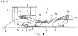
- FIG. 1 illustrates a turbomachine 1 which comprises, in a conventional manner, a fan S, a low-pressure compressor 1a, a high-pressure compressor 1b, an annular combustion chamber 1c, a high-pressure turbine 1d, a low-pressure turbine 1e and an exhaust nozzle 1h.
- the high-pressure compressor 1b and the high-pressure turbine 1d are connected by a high-pressure shaft 2 and form with it a high-pressure (HP) body.
- the low-pressure compressor 1a and the low-pressure turbine 1e are connected by a low-pressure shaft 3 and form with it a low-pressure (LP) body.
- the blower S is driven by a blower shaft 4 which is driven to the BP shaft 3 by means of a reducer 6.
- This reducer is generally of the planetary or epicyclic type.
- the reducer 6 is positioned in the upstream part of the turbomachine.
- a fixed structure schematically comprising, here, an upstream part 5a and a downstream part 5b which composes the motor casing or stator 5 is arranged so as to form an enclosure E surrounding the reducer 6.
- This enclosure E is here closed upstream by seals at a bearing allowing the fan shaft 4 to pass through, and downstream by seals at the crossing of the LP shaft 3.
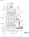
- FIG 2 illustrates a reducer 6 which can take the form of different architectures depending on whether certain parts are fixed or rotating.
- the reducer 6 is connected to the BP shaft 3, for example by means of splines 7a.
- the BP shaft 3 drives a pinion planetary called the solar 7.
- the number of satellites 8 is generally between three and seven for this type of application.
- the set of satellites 8 is held by a satellite carrier 10. Each satellite 8 rotates around its own Y axis, and meshes with the crown 9.
- all of the planet gears 8 rotate the planet carrier 10 about the axis X of the turbomachine.
- the ring gear is fixed to the engine casing or stator 5 via a ring gear carrier 12 and the planet carrier 10 is fixed to the fan shaft 4.
- all of the planet gears 8 are held by a ring gear carrier 10 which is fixed to the engine casing or stator 5.
- Each planet gear drives the ring gear which is attached to the fan shaft 4 via a ring gear carrier 12.
- Each satellite 8 is mounted to rotate freely using a bearing 11, for example of the rolling bearing or hydrostatic bearing type.
- Each bearing 11 is mounted on one of the axes 10b of the planet carrier 10 and all the axes are positioned relative to each other using one or more structural frames 10a of the planet carrier 10.
- the half-clamp 9ab of the front crown 9a and the half-clamp 9bb of the rear crown 9b form the crown mounting flange 9c.
- the crown 9 is fixed to a crown carrier by assembling the crown mounting flange 9c and the crown carrier mounting flange 12a using a bolted assembly for example.
- the arrows of the figure 2 describe the routing of the oil in the reducer 6.
- the oil arrives in the reducer 6 from the stator part 5 in the distributor 13 by different means which will not be specified in this view because they are specific to one or more types of architecture.
- the distributor is separated into 2 parts in general, each repeated by the same number of satellites.
- the injectors 13a have the function of lubricating the teeth and the arms 13b have the function of lubricating the bearings.
- the oil is supplied to the injector 13a to exit through the end 13c in order to lubricate the teeth.
- the oil is also supplied to the arm 13b and circulates via the supply mouth 13d of the bearing.
- the oil then circulates through the axis in one or more buffer zones 10c to then exit through the orifices 10d in order to lubricate the bearings of the satellites.
- FIG. 3 illustrates a planet carrier 10 devoid of such lubrication means or for which said lubrication means are not shown.
- the planet carrier 10 is here intended to form an output (epicyclic configuration) and comprises a splined male shaft 14, that is to say for which the splines 15 are external.
- Said shaft 14 is here a hollow shaft.
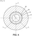
- the splines 15 of the shaft 14 of the planet carrier 10 are intended to cooperate with complementary splines 16 of an output shaft 17 connected to the fan S of the turbomachine 1, as illustrated in figures 4 And 5 .
- Each groove 15, 16 has a base 18, a top 19 and two sides 20.
- the sides 20 can be in the form of a circle, as illustrated in Figures 4 to 7 , or rights.
- a clearance j is formed between the bottoms 18 and the tops 19 of the grooves 15, 16.
- torque passes through the planet carrier 10 radially along directions or lines L each connecting one of the axes 10b of the planet carriers 8 and the axis X of the planet carrier 10.
- the invention proposes modifying the pitch of at least some of the splines 15 of the shaft 14.
- FIGs 8 and 9 illustrate the variation of ⁇ p as a function of the position of the groove 15.
- circle 21 represents the implantation diameter of the grooves 15 and curve C illustrates the evolution of ⁇ p as a function of the position of the corresponding groove 15 on the circumference.
- figure 9 is another type of representation illustrating in two dimensions the variation of ⁇ p (on the ordinate) relative to the position of the groove 15 (on the abscissa).
- the steps p of the grooves 15 are in particular modified so that the variation of ⁇ p as a function of the position of the corresponding groove 15 on the circumference generally follows a sinusoidal law oscillating between a maximum value ⁇ pmax and a minimum value ⁇ pmin and comprising three periods T on the circumference.
- the grooves 15 whose steps have a value of ⁇ p equal to or close to ⁇ pmin are located at the level of the aforementioned lines L.
- the grooves 15 whose steps have a value of ⁇ p equal to or close to ⁇ pmax are located circumferentially distant from the aforementioned lines L.
- FIGS. 10 and 11 correspond respectively to the Figures 8 and 9 and illustrate another type of variation of the difference ⁇ p, namely a variation in steps, here two steps: a minimum step ⁇ pmin and a maximum step ⁇ pmax.
- Several grooves 15 can thus have the same value ⁇ pmin, in the vicinity of the aforementioned lines L, and several grooves 15 can have the same value ⁇ pmax, at a distance from said lines L.
- the variation between the two steps can follow a continuous progressive law, for example linear.
- said variation by step can have more than two steps, for example four steps, namely a step of value ⁇ pmax, a step of value ⁇ pmin, a negative intermediate step, of value greater than ⁇ pmin and a positive intermediate step, of value less than ⁇ pmax.
- modifying the pitch p of at least some splines 15 makes it possible to make some splines 15 less active and to make other splines 15 more active, so as to better distribute the forces over all of the splines 15 distributed over the circumference of the splined hollow shaft 14.
- ⁇ pmax can be equal to - ⁇ pmin.
- ⁇ pmax can be between -100 microns and +100 microns, for example, for a nominal pitch of 7.98 mm, for example.
- ⁇ pmax can be between -500 microns and +500 microns, in particular between -200 microns and +200.
- the modification of the pitch of the grooves 15 can be obtained directly at the time of production of the grooves 15 or obtained after machining of at least part of the grooves 15, for example by grinding.
Landscapes
- Engineering & Computer Science (AREA)
- General Engineering & Computer Science (AREA)
- Mechanical Engineering (AREA)
- Chemical & Material Sciences (AREA)
- Combustion & Propulsion (AREA)
- Retarders (AREA)
- Shafts, Cranks, Connecting Bars, And Related Bearings (AREA)
Claims (9)
- Keilwelle (14) für Turbomaschinen bzw. Turbotriebwerke, die einen Umfang aufweist und Keilnuten (15) umfasst, die gleichmäßig über den Umfang verteilt sind, wobei die Keilnuten (15) voneinander beabstandet sind, zumindest ein Teil der Keilnuten (15) um eine modifizierte Teilung p in Bezug auf die nominale Teilung pn der Keilnuten (15) beabstandet ist, wobei das Verhältnis des Betrags der Differenz zwischen der modifizierten Teilung und der nominalen Teilung zur nominalen Teilung, d.h. |pn - p| / pn, ungleich Null ist, vorzugsweise zwischen 0,5 und 5 % liegt,
dadurch gekennzeichnet, dass über den Umfang der Keilwelle (14) gesehen die Differenz (Δp) zwischen der nominalen Teilung pn zwischen den Keilnuten (15) und der modifizierten Teilung p entlang des Umfangs von einer Keilnut (15) zur anderen allmählich zunimmt oder abnimmt, wobei die Differenz bis zu einem Maximum (Δpmax) zunimmt, bevor sie bis zu einem Minimum (Δpmin) abnimmt. - Keilwelle (14) nach dem vorhergehenden Anspruch,
wobei für zumindest einen Teil der Keilnuten (15) die Differenz (Δp) zwischen der modifizierten Teilung und der nominalen Teilung positiv ist, wobei die Keilnuten (15) als voreilend bezeichnet werden, und für zumindest einen anderen Teil der Keilnuten (15) die Differenz (Δp) zwischen der modifizierten Teilung und der nominalen Teilung negativ ist, wobei die Keilnuten (15) als nacheilend bezeichnet werden. - Keilwelle (14) nach einem der vorhergehenden Ansprüche,
wobei sie entlang des Umfangs zumindest eine Wechselfolge von voreilenden und nacheilenden Keilnuten (15) aufweist. - Keilwelle (14) nach dem vorhergehenden Anspruch,
wobei sie entlang des Umfangs mehrere aufeinanderfolgende Wechselfolgen von voreilenden und nacheilenden Keilnuten (15) aufweist. - Keilwelle (14) nach einem der vorhergehenden Ansprüche,
wobei die Differenz der Teilung zwischen den Keilnuten (15) zur nominalen Teilung entlang des Umfangs einen insgesamt sinusförmigen Verlauf zeigt. - Keilwelle (14) nach einem der Ansprüche 1 bis 4,
dadurch gekennzeichnet, dass die Differenz der Teilung zwischen den Keilnuten (15) zur nominalen Teilung entlang des Umfangs einen stufenweisen Verlauf zeigt. - Planetenradträger (10) für Planetengetriebe, mit zumindest einer Lagerachse (10b) zur Lagerung eines Planetenrads (8) und zumindest einer Keilwelle (14) nach einem der vorhergehenden Ansprüche.
- Planetenradträger nach Anspruch 7,
wobei zumindest eine nacheilende Keilnut (15) auf oder in der Nähe der Linie (L) liegt, die die Keilwelle (14) bzw. die Achse (X) des Planetenradträgers (10) einerseits und die Lagerachse (10b) des Planetenrads (8) andererseits verbindet, und/oder zumindest eine nacheilende Keilnut (15) von der Linie (L) entfernt liegt. - Planetengetriebe für Turbomaschinen bzw. Turbotriebwerke (1), mit zumindest einem Planetenradträger (10) nach einem der Ansprüche 7 oder 8.
Applications Claiming Priority (1)
| Application Number | Priority Date | Filing Date | Title |
|---|---|---|---|
| FR2108617A FR3126145B1 (fr) | 2021-08-10 | 2021-08-10 | Arbre cannelé |
Publications (2)
| Publication Number | Publication Date |
|---|---|
| EP4134562A1 EP4134562A1 (de) | 2023-02-15 |
| EP4134562B1 true EP4134562B1 (de) | 2024-08-21 |
Family
ID=77711235
Family Applications (1)
| Application Number | Title | Priority Date | Filing Date |
|---|---|---|---|
| EP22186961.3A Active EP4134562B1 (de) | 2021-08-10 | 2022-07-26 | Geriffelte welle |
Country Status (3)
| Country | Link |
|---|---|
| US (1) | US11927139B2 (de) |
| EP (1) | EP4134562B1 (de) |
| FR (1) | FR3126145B1 (de) |
Family Cites Families (12)
| Publication number | Priority date | Publication date | Assignee | Title |
|---|---|---|---|---|
| US2749086A (en) * | 1951-08-23 | 1956-06-05 | Rolls Royce | Rotor constructions for turbo machines |
| BE541360A (de) * | 1954-09-28 | |||
| FR2178431A5 (de) * | 1972-03-28 | 1973-11-09 | Renk Ag Zahnraeder | |
| JPS60124338U (ja) * | 1984-01-31 | 1985-08-22 | いすゞ自動車株式会社 | 自動車の動力分配装置 |
| JPH01105039A (ja) * | 1987-10-16 | 1989-04-21 | Shiyouji Igaku | 一体型非対称遊星歯車装置 |
| GB9302359D0 (en) * | 1993-02-06 | 1993-03-24 | Gkn Technology Ltd | Torque transmitting assemblies |
| JPH0673520U (ja) * | 1993-03-26 | 1994-10-18 | 日産ディーゼル工業株式会社 | 燃料噴射ポンプの軸受部分の構造 |
| JP2006307654A (ja) * | 2005-04-26 | 2006-11-09 | Fuji Heavy Ind Ltd | エンジンのマグネト取付構造 |
| JP6018472B2 (ja) * | 2012-10-10 | 2016-11-02 | アイシン・エーアイ株式会社 | スプライン連結構造 |
| DE202013004236U1 (de) * | 2013-05-04 | 2013-07-10 | Gkn Driveline International Gmbh | Welle-Nabe-Verbindung |
| US10683773B2 (en) * | 2018-05-25 | 2020-06-16 | Pratt & Whitney Canada Corp. | Planetary gearbox having compliant journal bearings |
| US11642913B2 (en) * | 2019-03-22 | 2023-05-09 | Shimano Inc. | Sprocket support body and bicycle hub assembly |
-
2021
- 2021-08-10 FR FR2108617A patent/FR3126145B1/fr active Active
-
2022
- 2022-07-26 EP EP22186961.3A patent/EP4134562B1/de active Active
- 2022-08-10 US US17/884,730 patent/US11927139B2/en active Active
Also Published As
| Publication number | Publication date |
|---|---|
| US20230051474A1 (en) | 2023-02-16 |
| FR3126145B1 (fr) | 2024-01-05 |
| EP4134562A1 (de) | 2023-02-15 |
| FR3126145A1 (fr) | 2023-02-17 |
| US11927139B2 (en) | 2024-03-12 |
Similar Documents
| Publication | Publication Date | Title |
|---|---|---|
| FR3095251A1 (fr) | Reducteur mecanique de turbomachine d’aeronef | |
| FR3111390A1 (fr) | Reducteur mecanique de turbomachine d’aeronef | |
| FR3095252A1 (fr) | Reducteur mecanique de turbomachine d’aeronef | |
| EP4303468B1 (de) | Sonnenrad für ein reduktionsgetriebe eines turbotriebwerks eines luftfahrzeugs | |
| FR3093550A1 (fr) | Reducteur mecanique de turbomachine d’aeronef | |
| EP3763932B1 (de) | Mechanisches reduktionsgetriebe für turbotriebwerk eines luftfahrzeugs | |
| EP4382769B1 (de) | Krone für ein mechanisches reduktionsgetriebe eines flugzeugs | |
| EP4336059B1 (de) | Gleitlager für ein mechanisches reduktionsgetriebe eines turbotriebwerks eines luftfahrzeugs | |
| EP4336070B1 (de) | Antriebsanordnung für ein mechanisches reduktionsgetriebe einer turbomaschine eines flugzeugs | |
| EP4056829A1 (de) | Kühlung von zahnrädern eines untersetzungsgetriebes eines turbinentriebwerks | |
| EP4134562B1 (de) | Geriffelte welle | |
| EP4033086A1 (de) | Turbotriebwerk für luftfahrzeug mit dreifacher strömung, das mit einem leistungsübertragungsmodul ausgestattet ist | |
| EP3974677B1 (de) | Verbessertes getriebe für die haltung des hohlrades | |
| EP4242489B1 (de) | Mechanisches reduktionsgetriebe für flugzeugturbomaschine | |
| EP4123190B1 (de) | Mechanisches untersetzungsgetriebe für gasturbomaschinen mit längsachse | |
| FR3153867A1 (fr) | Reducteur mecanique de turbomachine d’aeronef | |
| FR3139602A1 (fr) | Turbomachine d’aeronef a reducteur mecanique | |
| FR3159197A1 (fr) | Reducteur pour un aeronef | |
| FR3150247A1 (fr) | Turbomachine d’aeronef a double helice de propulsion | |
| FR3139870A1 (fr) | Ensemble de transmission pour un reducteur mecanique de turbomachine d’aeronef | |
| WO2025168906A1 (fr) | Couronne pour un reducteur mecanique d'une turbomachine d'aeronef | |
| WO2026074246A1 (fr) | Couronne mobile pour un reducteur mecanique d'aeronef | |
| WO2026003458A1 (fr) | Reducteur mecanique pour une turbomachine d'aeronef | |
| WO2026003460A1 (fr) | Porte-satellites pour un reducteur mecanique de turbomachine d'aeronef | |
| WO2025022053A1 (fr) | Reducteur mecanique pour une turbomachine |
Legal Events
| Date | Code | Title | Description |
|---|---|---|---|
| PUAI | Public reference made under article 153(3) epc to a published international application that has entered the european phase |
Free format text: ORIGINAL CODE: 0009012 |
|
| STAA | Information on the status of an ep patent application or granted ep patent |
Free format text: STATUS: THE APPLICATION HAS BEEN PUBLISHED |
|
| AK | Designated contracting states |
Kind code of ref document: A1 Designated state(s): AL AT BE BG CH CY CZ DE DK EE ES FI FR GB GR HR HU IE IS IT LI LT LU LV MC MK MT NL NO PL PT RO RS SE SI SK SM TR |
|
| STAA | Information on the status of an ep patent application or granted ep patent |
Free format text: STATUS: REQUEST FOR EXAMINATION WAS MADE |
|
| 17P | Request for examination filed |
Effective date: 20230418 |
|
| RBV | Designated contracting states (corrected) |
Designated state(s): AL AT BE BG CH CY CZ DE DK EE ES FI FR GB GR HR HU IE IS IT LI LT LU LV MC MK MT NL NO PL PT RO RS SE SI SK SM TR |
|
| GRAP | Despatch of communication of intention to grant a patent |
Free format text: ORIGINAL CODE: EPIDOSNIGR1 |
|
| STAA | Information on the status of an ep patent application or granted ep patent |
Free format text: STATUS: GRANT OF PATENT IS INTENDED |
|
| INTG | Intention to grant announced |
Effective date: 20240325 |
|
| RIN1 | Information on inventor provided before grant (corrected) |
Inventor name: PIGOTT, QUENTIN, PIERRE, HENRI Inventor name: MARCOS IZQUIERDO, JUAN-LUIS |
|
| GRAS | Grant fee paid |
Free format text: ORIGINAL CODE: EPIDOSNIGR3 |
|
| GRAA | (expected) grant |
Free format text: ORIGINAL CODE: 0009210 |
|
| STAA | Information on the status of an ep patent application or granted ep patent |
Free format text: STATUS: THE PATENT HAS BEEN GRANTED |
|
| AK | Designated contracting states |
Kind code of ref document: B1 Designated state(s): AL AT BE BG CH CY CZ DE DK EE ES FI FR GB GR HR HU IE IS IT LI LT LU LV MC MK MT NL NO PL PT RO RS SE SI SK SM TR |
|
| REG | Reference to a national code |
Ref country code: GB Ref legal event code: FG4D Free format text: NOT ENGLISH |
|
| REG | Reference to a national code |
Ref country code: CH Ref legal event code: EP |
|
| REG | Reference to a national code |
Ref country code: IE Ref legal event code: FG4D Free format text: LANGUAGE OF EP DOCUMENT: FRENCH |
|
| REG | Reference to a national code |
Ref country code: DE Ref legal event code: R096 Ref document number: 602022005444 Country of ref document: DE |
|
| REG | Reference to a national code |
Ref country code: LT Ref legal event code: MG9D |
|
| REG | Reference to a national code |
Ref country code: NL Ref legal event code: MP Effective date: 20240821 |
|
| PG25 | Lapsed in a contracting state [announced via postgrant information from national office to epo] |
Ref country code: NO Free format text: LAPSE BECAUSE OF FAILURE TO SUBMIT A TRANSLATION OF THE DESCRIPTION OR TO PAY THE FEE WITHIN THE PRESCRIBED TIME-LIMIT Effective date: 20241121 |
|
| REG | Reference to a national code |
Ref country code: AT Ref legal event code: MK05 Ref document number: 1715739 Country of ref document: AT Kind code of ref document: T Effective date: 20240821 |
|
| PG25 | Lapsed in a contracting state [announced via postgrant information from national office to epo] |
Ref country code: FI Free format text: LAPSE BECAUSE OF FAILURE TO SUBMIT A TRANSLATION OF THE DESCRIPTION OR TO PAY THE FEE WITHIN THE PRESCRIBED TIME-LIMIT Effective date: 20240821 Ref country code: NL Free format text: LAPSE BECAUSE OF FAILURE TO SUBMIT A TRANSLATION OF THE DESCRIPTION OR TO PAY THE FEE WITHIN THE PRESCRIBED TIME-LIMIT Effective date: 20240821 Ref country code: GR Free format text: LAPSE BECAUSE OF FAILURE TO SUBMIT A TRANSLATION OF THE DESCRIPTION OR TO PAY THE FEE WITHIN THE PRESCRIBED TIME-LIMIT Effective date: 20241122 Ref country code: PL Free format text: LAPSE BECAUSE OF FAILURE TO SUBMIT A TRANSLATION OF THE DESCRIPTION OR TO PAY THE FEE WITHIN THE PRESCRIBED TIME-LIMIT Effective date: 20240821 Ref country code: PT Free format text: LAPSE BECAUSE OF FAILURE TO SUBMIT A TRANSLATION OF THE DESCRIPTION OR TO PAY THE FEE WITHIN THE PRESCRIBED TIME-LIMIT Effective date: 20241223 |
|
| PG25 | Lapsed in a contracting state [announced via postgrant information from national office to epo] |
Ref country code: BG Free format text: LAPSE BECAUSE OF FAILURE TO SUBMIT A TRANSLATION OF THE DESCRIPTION OR TO PAY THE FEE WITHIN THE PRESCRIBED TIME-LIMIT Effective date: 20240821 |
|
| PG25 | Lapsed in a contracting state [announced via postgrant information from national office to epo] |
Ref country code: LV Free format text: LAPSE BECAUSE OF FAILURE TO SUBMIT A TRANSLATION OF THE DESCRIPTION OR TO PAY THE FEE WITHIN THE PRESCRIBED TIME-LIMIT Effective date: 20240821 |
|
| PG25 | Lapsed in a contracting state [announced via postgrant information from national office to epo] |
Ref country code: IS Free format text: LAPSE BECAUSE OF FAILURE TO SUBMIT A TRANSLATION OF THE DESCRIPTION OR TO PAY THE FEE WITHIN THE PRESCRIBED TIME-LIMIT Effective date: 20241221 Ref country code: AT Free format text: LAPSE BECAUSE OF FAILURE TO SUBMIT A TRANSLATION OF THE DESCRIPTION OR TO PAY THE FEE WITHIN THE PRESCRIBED TIME-LIMIT Effective date: 20240821 |
|
| PG25 | Lapsed in a contracting state [announced via postgrant information from national office to epo] |
Ref country code: HR Free format text: LAPSE BECAUSE OF FAILURE TO SUBMIT A TRANSLATION OF THE DESCRIPTION OR TO PAY THE FEE WITHIN THE PRESCRIBED TIME-LIMIT Effective date: 20240821 |
|
| PG25 | Lapsed in a contracting state [announced via postgrant information from national office to epo] |
Ref country code: RS Free format text: LAPSE BECAUSE OF FAILURE TO SUBMIT A TRANSLATION OF THE DESCRIPTION OR TO PAY THE FEE WITHIN THE PRESCRIBED TIME-LIMIT Effective date: 20241121 Ref country code: ES Free format text: LAPSE BECAUSE OF FAILURE TO SUBMIT A TRANSLATION OF THE DESCRIPTION OR TO PAY THE FEE WITHIN THE PRESCRIBED TIME-LIMIT Effective date: 20240821 |
|
| PG25 | Lapsed in a contracting state [announced via postgrant information from national office to epo] |
Ref country code: RS Free format text: LAPSE BECAUSE OF FAILURE TO SUBMIT A TRANSLATION OF THE DESCRIPTION OR TO PAY THE FEE WITHIN THE PRESCRIBED TIME-LIMIT Effective date: 20241121 Ref country code: PT Free format text: LAPSE BECAUSE OF FAILURE TO SUBMIT A TRANSLATION OF THE DESCRIPTION OR TO PAY THE FEE WITHIN THE PRESCRIBED TIME-LIMIT Effective date: 20241223 Ref country code: PL Free format text: LAPSE BECAUSE OF FAILURE TO SUBMIT A TRANSLATION OF THE DESCRIPTION OR TO PAY THE FEE WITHIN THE PRESCRIBED TIME-LIMIT Effective date: 20240821 Ref country code: NO Free format text: LAPSE BECAUSE OF FAILURE TO SUBMIT A TRANSLATION OF THE DESCRIPTION OR TO PAY THE FEE WITHIN THE PRESCRIBED TIME-LIMIT Effective date: 20241121 Ref country code: NL Free format text: LAPSE BECAUSE OF FAILURE TO SUBMIT A TRANSLATION OF THE DESCRIPTION OR TO PAY THE FEE WITHIN THE PRESCRIBED TIME-LIMIT Effective date: 20240821 Ref country code: LV Free format text: LAPSE BECAUSE OF FAILURE TO SUBMIT A TRANSLATION OF THE DESCRIPTION OR TO PAY THE FEE WITHIN THE PRESCRIBED TIME-LIMIT Effective date: 20240821 Ref country code: IS Free format text: LAPSE BECAUSE OF FAILURE TO SUBMIT A TRANSLATION OF THE DESCRIPTION OR TO PAY THE FEE WITHIN THE PRESCRIBED TIME-LIMIT Effective date: 20241221 Ref country code: HR Free format text: LAPSE BECAUSE OF FAILURE TO SUBMIT A TRANSLATION OF THE DESCRIPTION OR TO PAY THE FEE WITHIN THE PRESCRIBED TIME-LIMIT Effective date: 20240821 Ref country code: GR Free format text: LAPSE BECAUSE OF FAILURE TO SUBMIT A TRANSLATION OF THE DESCRIPTION OR TO PAY THE FEE WITHIN THE PRESCRIBED TIME-LIMIT Effective date: 20241122 Ref country code: FI Free format text: LAPSE BECAUSE OF FAILURE TO SUBMIT A TRANSLATION OF THE DESCRIPTION OR TO PAY THE FEE WITHIN THE PRESCRIBED TIME-LIMIT Effective date: 20240821 Ref country code: ES Free format text: LAPSE BECAUSE OF FAILURE TO SUBMIT A TRANSLATION OF THE DESCRIPTION OR TO PAY THE FEE WITHIN THE PRESCRIBED TIME-LIMIT Effective date: 20240821 Ref country code: BG Free format text: LAPSE BECAUSE OF FAILURE TO SUBMIT A TRANSLATION OF THE DESCRIPTION OR TO PAY THE FEE WITHIN THE PRESCRIBED TIME-LIMIT Effective date: 20240821 Ref country code: AT Free format text: LAPSE BECAUSE OF FAILURE TO SUBMIT A TRANSLATION OF THE DESCRIPTION OR TO PAY THE FEE WITHIN THE PRESCRIBED TIME-LIMIT Effective date: 20240821 |
|
| PG25 | Lapsed in a contracting state [announced via postgrant information from national office to epo] |
Ref country code: SM Free format text: LAPSE BECAUSE OF FAILURE TO SUBMIT A TRANSLATION OF THE DESCRIPTION OR TO PAY THE FEE WITHIN THE PRESCRIBED TIME-LIMIT Effective date: 20240821 Ref country code: DK Free format text: LAPSE BECAUSE OF FAILURE TO SUBMIT A TRANSLATION OF THE DESCRIPTION OR TO PAY THE FEE WITHIN THE PRESCRIBED TIME-LIMIT Effective date: 20240821 Ref country code: RO Free format text: LAPSE BECAUSE OF FAILURE TO SUBMIT A TRANSLATION OF THE DESCRIPTION OR TO PAY THE FEE WITHIN THE PRESCRIBED TIME-LIMIT Effective date: 20240821 |
|
| PG25 | Lapsed in a contracting state [announced via postgrant information from national office to epo] |
Ref country code: EE Free format text: LAPSE BECAUSE OF FAILURE TO SUBMIT A TRANSLATION OF THE DESCRIPTION OR TO PAY THE FEE WITHIN THE PRESCRIBED TIME-LIMIT Effective date: 20240821 |
|
| PG25 | Lapsed in a contracting state [announced via postgrant information from national office to epo] |
Ref country code: CZ Free format text: LAPSE BECAUSE OF FAILURE TO SUBMIT A TRANSLATION OF THE DESCRIPTION OR TO PAY THE FEE WITHIN THE PRESCRIBED TIME-LIMIT Effective date: 20240821 |
|
| PG25 | Lapsed in a contracting state [announced via postgrant information from national office to epo] |
Ref country code: SK Free format text: LAPSE BECAUSE OF FAILURE TO SUBMIT A TRANSLATION OF THE DESCRIPTION OR TO PAY THE FEE WITHIN THE PRESCRIBED TIME-LIMIT Effective date: 20240821 Ref country code: IT Free format text: LAPSE BECAUSE OF FAILURE TO SUBMIT A TRANSLATION OF THE DESCRIPTION OR TO PAY THE FEE WITHIN THE PRESCRIBED TIME-LIMIT Effective date: 20240821 |
|
| REG | Reference to a national code |
Ref country code: DE Ref legal event code: R097 Ref document number: 602022005444 Country of ref document: DE |
|
| PLBE | No opposition filed within time limit |
Free format text: ORIGINAL CODE: 0009261 |
|
| STAA | Information on the status of an ep patent application or granted ep patent |
Free format text: STATUS: NO OPPOSITION FILED WITHIN TIME LIMIT |
|
| 26N | No opposition filed |
Effective date: 20250522 |
|
| PG25 | Lapsed in a contracting state [announced via postgrant information from national office to epo] |
Ref country code: SE Free format text: LAPSE BECAUSE OF FAILURE TO SUBMIT A TRANSLATION OF THE DESCRIPTION OR TO PAY THE FEE WITHIN THE PRESCRIBED TIME-LIMIT Effective date: 20240821 |
|
| PGFP | Annual fee paid to national office [announced via postgrant information from national office to epo] |
Ref country code: DE Payment date: 20250722 Year of fee payment: 4 |
|
| PGFP | Annual fee paid to national office [announced via postgrant information from national office to epo] |
Ref country code: FR Payment date: 20250722 Year of fee payment: 4 |
|
| REG | Reference to a national code |
Ref country code: CH Ref legal event code: H13 Free format text: ST27 STATUS EVENT CODE: U-0-0-H10-H13 (AS PROVIDED BY THE NATIONAL OFFICE) Effective date: 20260224 |
|
| PG25 | Lapsed in a contracting state [announced via postgrant information from national office to epo] |
Ref country code: LU Free format text: LAPSE BECAUSE OF NON-PAYMENT OF DUE FEES Effective date: 20250726 |
|
| REG | Reference to a national code |
Ref country code: BE Ref legal event code: MM Effective date: 20250731 |
|
| PG25 | Lapsed in a contracting state [announced via postgrant information from national office to epo] |
Ref country code: BE Free format text: LAPSE BECAUSE OF NON-PAYMENT OF DUE FEES Effective date: 20250731 |
|
| PG25 | Lapsed in a contracting state [announced via postgrant information from national office to epo] |
Ref country code: CH Free format text: LAPSE BECAUSE OF NON-PAYMENT OF DUE FEES Effective date: 20250731 |