EP4134930B1 - Dispositif et système de sécurité électrique - Google Patents
Dispositif et système de sécurité électrique Download PDFInfo
- Publication number
- EP4134930B1 EP4134930B1 EP22199191.2A EP22199191A EP4134930B1 EP 4134930 B1 EP4134930 B1 EP 4134930B1 EP 22199191 A EP22199191 A EP 22199191A EP 4134930 B1 EP4134930 B1 EP 4134930B1
- Authority
- EP
- European Patent Office
- Prior art keywords
- electrical
- sensor
- hazard
- electrical safety
- electrical appliance
- Prior art date
- Legal status (The legal status is an assumption and is not a legal conclusion. Google has not performed a legal analysis and makes no representation as to the accuracy of the status listed.)
- Active
Links
Images




Classifications
-
- G—PHYSICS
- G05—CONTROLLING; REGULATING
- G05B—CONTROL OR REGULATING SYSTEMS IN GENERAL; FUNCTIONAL ELEMENTS OF SUCH SYSTEMS; MONITORING OR TESTING ARRANGEMENTS FOR SUCH SYSTEMS OR ELEMENTS
- G05B19/00—Program-control systems
- G05B19/02—Program-control systems electric
- G05B19/04—Program control other than numerical control, i.e. in sequence controllers or logic controllers
- G05B19/042—Program control other than numerical control, i.e. in sequence controllers or logic controllers using digital processors
- G05B19/0428—Safety, monitoring
-
- G—PHYSICS
- G01—MEASURING; TESTING
- G01J—MEASUREMENT OF INTENSITY, VELOCITY, SPECTRAL CONTENT, POLARISATION, PHASE OR PULSE CHARACTERISTICS OF INFRARED, VISIBLE OR ULTRAVIOLET LIGHT; COLORIMETRY; RADIATION PYROMETRY
- G01J5/00—Radiation pyrometry, e.g. infrared or optical thermometry
- G01J5/0096—Radiation pyrometry, e.g. infrared or optical thermometry for measuring wires, electrical contacts or electronic systems
-
- G—PHYSICS
- G01—MEASURING; TESTING
- G01J—MEASUREMENT OF INTENSITY, VELOCITY, SPECTRAL CONTENT, POLARISATION, PHASE OR PULSE CHARACTERISTICS OF INFRARED, VISIBLE OR ULTRAVIOLET LIGHT; COLORIMETRY; RADIATION PYROMETRY
- G01J5/00—Radiation pyrometry, e.g. infrared or optical thermometry
- G01J5/10—Radiation pyrometry, e.g. infrared or optical thermometry using electric radiation detectors
- G01J5/12—Radiation pyrometry, e.g. infrared or optical thermometry using electric radiation detectors using thermoelectric elements, e.g. thermocouples
-
- G—PHYSICS
- G01—MEASURING; TESTING
- G01K—MEASURING TEMPERATURE; MEASURING QUANTITY OF HEAT; THERMALLY-SENSITIVE ELEMENTS NOT OTHERWISE PROVIDED FOR
- G01K13/00—Thermometers specially adapted for specific purposes
-
- G—PHYSICS
- G08—SIGNALLING
- G08B—SIGNALLING SYSTEMS, e.g. PERSONAL CALLING SYSTEMS; ORDER TELEGRAPHS; ALARM SYSTEMS
- G08B17/00—Fire alarms; Alarms responsive to explosion
- G08B17/06—Electric actuation of the alarm, e.g. using a thermally-operated switch
-
- G—PHYSICS
- G08—SIGNALLING
- G08B—SIGNALLING SYSTEMS, e.g. PERSONAL CALLING SYSTEMS; ORDER TELEGRAPHS; ALARM SYSTEMS
- G08B17/00—Fire alarms; Alarms responsive to explosion
- G08B17/10—Actuation by presence of smoke or gases, e.g. automatic alarm devices for analysing flowing fluid materials by the use of optical means
-
- G—PHYSICS
- G08—SIGNALLING
- G08B—SIGNALLING SYSTEMS, e.g. PERSONAL CALLING SYSTEMS; ORDER TELEGRAPHS; ALARM SYSTEMS
- G08B17/00—Fire alarms; Alarms responsive to explosion
- G08B17/12—Actuation by presence of radiation or particles, e.g. of infrared radiation or of ions
-
- G—PHYSICS
- G08—SIGNALLING
- G08B—SIGNALLING SYSTEMS, e.g. PERSONAL CALLING SYSTEMS; ORDER TELEGRAPHS; ALARM SYSTEMS
- G08B21/00—Alarms responsive to a single specified undesired or abnormal condition and not otherwise provided for
- G08B21/02—Alarms for ensuring the safety of persons
- G08B21/12—Alarms for ensuring the safety of persons responsive to undesired emission of substances, e.g. pollution alarms
- G08B21/14—Toxic gas alarms
-
- G—PHYSICS
- G08—SIGNALLING
- G08B—SIGNALLING SYSTEMS, e.g. PERSONAL CALLING SYSTEMS; ORDER TELEGRAPHS; ALARM SYSTEMS
- G08B21/00—Alarms responsive to a single specified undesired or abnormal condition and not otherwise provided for
- G08B21/18—Status alarms
-
- G—PHYSICS
- G08—SIGNALLING
- G08B—SIGNALLING SYSTEMS, e.g. PERSONAL CALLING SYSTEMS; ORDER TELEGRAPHS; ALARM SYSTEMS
- G08B21/00—Alarms responsive to a single specified undesired or abnormal condition and not otherwise provided for
- G08B21/18—Status alarms
- G08B21/182—Level alarms, e.g. alarms responsive to variables exceeding a threshold
-
- G—PHYSICS
- G08—SIGNALLING
- G08C—TRANSMISSION SYSTEMS FOR MEASURED VALUES, CONTROL OR SIMILAR SIGNALS
- G08C17/00—Arrangements for transmitting signals characterised by the use of a wireless electrical link
- G08C17/02—Arrangements for transmitting signals characterised by the use of a wireless electrical link using a radio link
-
- H—ELECTRICITY
- H01—ELECTRIC ELEMENTS
- H01R—ELECTRICALLY-CONDUCTIVE CONNECTIONS; STRUCTURAL ASSOCIATIONS OF A PLURALITY OF MUTUALLY-INSULATED ELECTRICAL CONNECTING ELEMENTS; COUPLING DEVICES; CURRENT COLLECTORS
- H01R13/00—Details of coupling devices of the kinds covered by groups H01R12/70 or H01R24/00 - H01R33/00
- H01R13/66—Structural association with built-in electrical component
- H01R13/70—Structural association with built-in electrical component with built-in switch
- H01R13/713—Structural association with built-in electrical component with built-in switch the switch being a safety switch
- H01R13/7137—Structural association with built-in electrical component with built-in switch the switch being a safety switch with thermal interrupter
-
- H—ELECTRICITY
- H02—GENERATION; CONVERSION OR DISTRIBUTION OF ELECTRIC POWER
- H02H—EMERGENCY PROTECTIVE CIRCUIT ARRANGEMENTS
- H02H1/00—Details of emergency protective circuit arrangements
- H02H1/0007—Details of emergency protective circuit arrangements concerning the detecting means
- H02H1/0015—Using arc detectors
- H02H1/0023—Using arc detectors sensing non electrical parameters, e.g. by optical, pneumatic, thermal or sonic sensors
-
- H—ELECTRICITY
- H02—GENERATION; CONVERSION OR DISTRIBUTION OF ELECTRIC POWER
- H02H—EMERGENCY PROTECTIVE CIRCUIT ARRANGEMENTS
- H02H3/00—Emergency protective circuit arrangements for automatic disconnection directly responsive to an undesired change from normal electric working condition with or without subsequent reconnection ; integrated protection
- H02H3/02—Details
- H02H3/04—Details with warning or supervision in addition to disconnection, e.g. for indicating that protective apparatus has functioned
-
- H—ELECTRICITY
- H02—GENERATION; CONVERSION OR DISTRIBUTION OF ELECTRIC POWER
- H02H—EMERGENCY PROTECTIVE CIRCUIT ARRANGEMENTS
- H02H5/00—Emergency protective circuit arrangements for automatic disconnection directly responsive to an undesired change from normal non-electric working conditions with or without subsequent reconnection
- H02H5/04—Emergency protective circuit arrangements for automatic disconnection directly responsive to an undesired change from normal non-electric working conditions with or without subsequent reconnection responsive to abnormal temperature
- H02H5/045—Emergency protective circuit arrangements for automatic disconnection directly responsive to an undesired change from normal non-electric working conditions with or without subsequent reconnection responsive to abnormal temperature using a thermal radiation sensor
-
- G—PHYSICS
- G01—MEASURING; TESTING
- G01J—MEASUREMENT OF INTENSITY, VELOCITY, SPECTRAL CONTENT, POLARISATION, PHASE OR PULSE CHARACTERISTICS OF INFRARED, VISIBLE OR ULTRAVIOLET LIGHT; COLORIMETRY; RADIATION PYROMETRY
- G01J5/00—Radiation pyrometry, e.g. infrared or optical thermometry
- G01J5/10—Radiation pyrometry, e.g. infrared or optical thermometry using electric radiation detectors
- G01J5/12—Radiation pyrometry, e.g. infrared or optical thermometry using electric radiation detectors using thermoelectric elements, e.g. thermocouples
- G01J2005/123—Thermoelectric array
-
- G—PHYSICS
- G01—MEASURING; TESTING
- G01K—MEASURING TEMPERATURE; MEASURING QUANTITY OF HEAT; THERMALLY-SENSITIVE ELEMENTS NOT OTHERWISE PROVIDED FOR
- G01K2207/00—Application of thermometers in household appliances
-
- G—PHYSICS
- G05—CONTROLLING; REGULATING
- G05B—CONTROL OR REGULATING SYSTEMS IN GENERAL; FUNCTIONAL ELEMENTS OF SUCH SYSTEMS; MONITORING OR TESTING ARRANGEMENTS FOR SUCH SYSTEMS OR ELEMENTS
- G05B2219/00—Program-control systems
- G05B2219/20—Pc systems
- G05B2219/24—Pc safety
- G05B2219/24024—Safety, surveillance
-
- G—PHYSICS
- G08—SIGNALLING
- G08B—SIGNALLING SYSTEMS, e.g. PERSONAL CALLING SYSTEMS; ORDER TELEGRAPHS; ALARM SYSTEMS
- G08B21/00—Alarms responsive to a single specified undesired or abnormal condition and not otherwise provided for
- G08B21/18—Status alarms
- G08B21/185—Electrical failure alarms
-
- G—PHYSICS
- G08—SIGNALLING
- G08B—SIGNALLING SYSTEMS, e.g. PERSONAL CALLING SYSTEMS; ORDER TELEGRAPHS; ALARM SYSTEMS
- G08B3/00—Audible signalling systems, e.g. audible personal calling systems
- G08B3/10—Audible signalling systems, e.g. audible personal calling systems using electric transmission; using electromagnetic transmission
-
- G—PHYSICS
- G08—SIGNALLING
- G08B—SIGNALLING SYSTEMS, e.g. PERSONAL CALLING SYSTEMS; ORDER TELEGRAPHS; ALARM SYSTEMS
- G08B5/00—Visible signalling systems, e.g. visible personal calling systems or remote indication of seats occupied
- G08B5/22—Visible signalling systems, e.g. visible personal calling systems or remote indication of seats occupied using electric transmission; using electromagnetic transmission
Definitions
- the present invention relates to a system comprising an electrical appliance and one or more remote devices for detecting the presence of an electrical hazard and addressing an electrical hazard.
- an electrical safety system comprising an electrical appliance and one or more remote devices, the electrical appliance comprising: a housing; electrical components within the housing configured to provide a function of the electrical appliance; a thermal sensor arranged to detect the surface temperature of the electrical components; and a processor in communication with the thermal sensor, the processor configured to determine when the sensed surface temperature exceeds a predetermined threshold.
- the electrical safety device further includes a relay switch configured to disconnect the mains current supply to an electrical appliance connected to the electrical safety device when the processor determines that the surface temperature of the plug exceeds the predetermined threshold. In this way, if the temperature of the plug of an electrical appliance reaches a level deemed to be hazardous, the electrical safety device can block the supply of current to the appliance, thereby addressing the hazard.
- At least one remote device comprises a smart user device and the smart user device is configured to provide an audio or visual alert after receiving a signal from the electrical safety device.
- a smart phone may run software configured to operate with the electrical safety system. The software may display alerts to a user, identify the location of an identified risk, provide details of the identified risk, allow a user to choose an option to address the risk such as shutting off a mains or local supply of gas, water, electricity, activate a sprinkler system, call the fire brigade or turn an appliance off.
- At least one remote device comprises a voice assistant device (such as Apple TM Siri, Google TM Assistant, Microsoft TM Cortana, Amazon TM Alexa) where the voice assistant device is configured to notify a user upon receiving a signal from the electrical safety device.
- the voice assistant device may be configured to provide one or more of: information on the type and location of the hazard, provide options for responding (e.g. call emergency services, activate an isolation device) or information on how to safely exit the building to avoid the hazard.
- At least one remote device comprises an isolation unit comprising a communications link; wherein the isolation unit is configured to restrict a flow of water, gas or electricity through the isolation unit upon receiving a signal from the electrical safety device.
- an isolation unit can receive a communication from an electrical safety device that an appliance is exhibiting behaviour indicative of a fault and the isolation device can take action to restrict or prevent the flow of services to that specific appliance, to a part of the building or to the building as a whole.
- the isolation units may take several different forms.
- at least one isolation unit comprises a local water isolation unit arranged for installation at the local water connection to an electrical appliance; the local water isolation unit comprising: a cabled or wireless connection for connecting to the electrical safety device; and a motorised valve; wherein the local water isolation unit is configured to close the motorised valve to restrict the water supply to the electrical appliance upon receiving a signal from the electrical safety device.
- the water supply to a particular appliance, group of appliances or region of a building can be restricted to prevent flooding or an electrical fault being spread by water.
- At least one isolation unit comprises a mains supply isolation unit comprising: at least one motorised valve arranged for installation in a mains water feed, a header water tank or mains gas supply; wherein the mains supply isolation unit is configured to close the motorised valve to restrict the mains supply upon receiving a signal from the electrical safety device.
- at least one isolation unit comprises a mains electrical isolation unit comprising: a mains electrical shut off switch; wherein the electrical isolation unit is configured to actuate the electrical shut off switch to shut off the mains electricity upon receiving a signal from the electrical safety device.
- the main electrical isolation unit may be connected to a mains consumer unit and is configured to actuate a main switch on the mains consumer unit to shut off the main electricity supply.
- the mains electrical isolation unit may be integrated within the consumer unit or fuse box.
- the isolation unit may include one or more local sensors to identify a local hazard.
- the isolation unit comprises a processor and one or more of: a thermal sensor; a smoke and/or gas sensor; a carbon monoxide sensor; a moisture and/or water sensor; a current sensor; wherein the isolation unit is configured restrict a flow of water, gas or electricity when the processor determines that a parameter sensed by a local sensor exceeds a predetermined threshold.
- FIG. 1 illustrates an electrical safety device 100.
- the electrical safety device 100 includes a socket 120 arranged to receive an electrical plug of an electrical appliance and a thermal sensor 110 arranged to detect the surface temperature of an electrical plug when it is received in the socket 120 of the electrical safety device 100.
- the electrical safety device 100 further includes a processor (internal to the device and not pictured) which is in communication with the thermal sensor 110 and is configured to determine when the sensed surface temperature of an electrical plug received in the socket 120 exceeds a predetermined threshold. Since the thermal sensor 110 is arranged to detect the surface temperature of an electrical plug received in the socket 120, the electrical safety device 100 allows for early detection of hazardous conditions which could result in a fire.
- a primary cause of house fires is the overheating due to an electrical fault in an electrical appliance.
- Such electrical faults can be determined by an increased in surface temperature of the mains plug connection such that, by monitoring this parameter, electrical faults can be detected before they escalate.
- the thermal sensor 110 is arranged to provide a contactless temperature measurement of the electrical plug of an electrical appliance when connected to the socket 20.
- the use of contactless thermal imaging allows for imaging of the electrical plug as a whole, allowing for temperature changes to be detected across the plug rather than from single point as necessitated by a contact measurement.
- a contact measurement requires that a contact temperature sensor is provided so as to remain in contact with the electrical plug when it is received in the socket 120. If the contact temperature sensor is dislodged out of place such that it is no longer in contact with the electrical plug it will no longer provide an accurate temperature measurement such that there is a risk that a hazardous fault in the electrical appliance will not be detected.
- An infrared array sensor also provides for the possibility of more complex processing carried out on the thermal image received by the sensor. For example, more advanced machine learning based algorithms can be used to detect temperature change patterns which are indicative of a high risk fault in the appliance.
- Figures 2 and 3 illustrate an alternative possibility in which the thermal sensor 110 is positioned on the surface of the housing 130 directed along the surface 131 of the housing 130 so as to measure the surface temperature of the electrical plug.
- the thermal sensor 110 may be moulded within the housing 130 of the electrical safety device 100.
- the housing 130 comprises an integral protruding portion 112 in the surface 131 which houses the infrared sensor so as to direct it along the face of the housing 130 towards the socket portion 120.
- Figure 2B shows a side profile view of the electrical device 100 of Figure 2A .
- the protruding housing portion 112 is visible in the surface 131 of the housing 130.
- the thermal sensor 110 is held within this protruding housing portion 112 so as to be aligned approximately parallel with the surface of the housing 130.
- the sensor 110 may be positioned at any point around the socket portion 120, for example directed at the socket 120 from the side as shown in Figure 2A , from below as shown in Figure 3 or from above. Positioning the sensor in this way so as to be directed along the surface of the housing allows the sensor to be distanced from the plug so as to image a wider field of view around the plug when received in the socket. Given the lens of the thermal sensor 110 provides a field of view of around 60°, a substantial portion of the electrical plug can be imaged to detect rising temperature gradients as they arise, allowing more accurate detection of temperature rises associated with electrical faults.
- the thermal sensor 110 is primarily configured for detection of surface temperature, which allows an early detection of possible faults, before they result in significant temperature rises leading to sparks or flames, the thermal sensor can clearly equally detect the presence of such sparks or flames as they arise in the plug due to significant emission of IR radiation.
- the thermal sensor 110 therefore allows for the early detection of temperature increases associated with possible hazardous faults within the device and the device can provide various alerts and actions to minimise the risk of such faults, as will now be described.
- FIG 2A illustrates various further functionality of an electrical safety device.
- the electrical safety device 100 shown in Figures 1 and 2A is a mains socket faceplate 100, which is configured to be mounted at an electrical connection point on a wall or other surface, for example using screws 101.
- the main socket face plate safety device 100 of Figures 1a and 2A comprises a substantially flat body defined by a housing 130, as in a conventional main socket face plate or fascia.
- the electrical safety main socket face plate 100 is configured to be positioned in place of a conventional main socket face plate at the electrical access points in a building to provide enhanced safety against the risk of fires and electrical faults.
- the main socket face plate device 100 includes switches 102 to switch on the current supply to the corresponding socket 120, as in a conventional mains socket face plate.
- the main socket face plate device 100 is attached to a wall by screwing it into place using screws 101, in place of a conventional main socket face plate.
- An electrical appliance is plugged into a socket 120 of the device 100 and current supplied by switching switch 102 to the on position.
- the surface temperature of an appliance plug plugged into the socket 120 is monitored by the thermal infrared sensor 110 facing along the surface of the housing 130 directed at the socket 120.
- the processor not shown
- the device 100 determines the presence of a possible risk and can take a number of actions.
- the electrical safety device 100 firstly comprises an internal alarm sounder 140 which is configured to sound when a hazard is detected in order to alert the occupants in the surrounding area. Furthermore, the electrical safety device comprises a wireless communications link configured to communicate with one or more remote devices. In particular, the device 100 is configured to communicate via the communications link to a user device such as a smartphone in order to alert a user of the presence of a potential electrical fault and provide further information regarding the type of hazard detected and its position within the building.
- a user device such as a smartphone in order to alert a user of the presence of a potential electrical fault and provide further information regarding the type of hazard detected and its position within the building.
- the device 100 contains a reset switch 141 for resetting the device 100 or silencing the alarm 140 when it is sounding.
- the electrical safety device 100 further comprises a series of status LEDs to indicate to a user that the device 100 is functioning correctly.
- the device of Figure 2A includes a corresponding LED to indicate the status for the network connectivity, the power to the device and the sounding of the alarm.
- the series of LEDs 142 are provided on the surface of the housing 130 to provide visual alert to the user.
- the electrical safety device may equally be configured to communicate via the wireless communications link with other user devices such as a smart TV, smart watch or other devices to indicate the presence of a potential hazard and provide details on the hazard detected.
- Each of the sensors are electrically connected to the processor within the device such that the processor can calculate whether any of the sensed parameters are indicative of a potential hazard.
- the processor is configured to determine the presence of a potential hazard by identifying when the value of a sensed parameter exceeds a predetermined threshold value. However more complex processing may be used to identify the presence of a hazard, for example by identifying a rate of change of a sensed parameter or where a sensed parameter change displays a particular behaviour or pattern associated with an increased risk of a hazard.
- the processor can also be configured to determine the presence of a hazard based on a combination of sensor outputs in order to identify a risk more reliably.
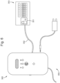
- the electrical safety device 100 can also include a water sensor 116 arranged to detect the presence of water in the vicinity of the device 100, as shown in Figure 2A .
- the water sensor 116 may comprise a water sensor body 117 arranged to lie on the ground below the electrical safety device 100 so as to detect collecting water on a surface below the device 100.
- the water sensor body 117 is connected to the device by a water sensor connection 118 as shown in Figure 2A .
- the connection 118 may comprise a plug which plugs into a corresponding socket on the side of the device to connect the water sensor to the internal processor such that the processor can receive signals from the water sensor to identify the presence of water and alert a user using the alarm or wireless communications link to a user device.
- the presence of water may be particularly hazardous when there is an electrical fault with the appliance and the additional water sensor 116 can detect the presence of a leak from a household appliance or mains water in order to identify such a hazard.
- the electrical safety device 100 also includes a relay switch within the device 100 which is configured to disconnect the current supply to an electrical appliance connected to the electrical safety device 100 when the processor determines the presence of a hazard via signals received from one or more sensors. In this way, if a fault within the appliances detected the electrical supply from the mains electricity supply through the electrical safety device 100 can be stopped immediately to prevent the hazard developing further.
- the electrical appliance also comprises a wireless communications link so it can be integrated in the above described electrical safety system to achieve the processes and advantages described above.
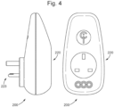
- An electrical safety plug adapter comprises a socket, arranged to receive a plug of an external device, and a plug part, arranged to be inserted to a socket of an external power supply, such as a mains wall socket.
- the plug adapter is generally arranged to provide selective electrical connection between an electrical appliance (external device) and a household power supply (mains wall socket).
- the adapter device includes at least one hazard sensor that is able to determine a potential hazard and disconnect the external device from the power supply. In this way, the adapter device can provide local detection of the hazard and prevent the external device from exacerbating the hazard. For example, if a refrigerator catches fire, the power supply to the refrigerator can be turned off which prevents the refrigerator from exacerbating the fire conditions. Additionally, earlier detection of a hazard is more likely that conventional detection systems as the sensors are closer to probably hazard causes.
- the socket and plug part are connected through an internal circuitry of the adapter.
- the internal circuit may include a relay, arranged to selectively control the current between the plug part and the socket. Alternative means for selectively turning off power supply to the external devices are also contemplated.
- the internal circuitry may also include components for wireless communication, such as Mesh Radio Network, Wi-Fi and Bluetooth chipsets.
- the adapter further comprises an integrated set of hazard detection sensors, such as CO, CO2, smoke, gas, thermal, flame and water detection sensors. Each of the sensors are connected, through the internal circuitry, to the network of the system.
- hazard detection sensors such as CO, CO2, smoke, gas, thermal, flame and water detection sensors.
- the gas sensor is arranged to sense ambient levels of hazardous gas, such as combustible, flammable and toxic gases.
- the gas sensor may comprise sensing components arranged to utilise any, or a combination, of electrochemical, pellistor, photoionisation, infrared point, semiconductor detection methods.
- the gas detector communicates with the internal circuitry to indicate a risk of gas leakage or fire.
- the carbon monoxide sensor is arranged to sense ambient levels of carbon monoxide (CO).
- the CO sensor may comprise sensing components arranged to utilise any, or a combination of, biomimetic, electrochemical, opto-chemical and semi-conductor sensing methods.
- the CO detector communicates with the internal circuitry to indicate a risk of CO leakage or fire.
- Additional thermal sensors may monitor connections within the device to identify abnormal current flow or local hazard causing conditions.
- a further IR thermal sensor may create a thermal image of a local area and identify a hazard before it spreads.
- the adapter In the event that one of the on-board sensors detects a parameter which indicates a potential hazard and/or fire, the adapter automatically actuates the relay such that the electrical connection between the plug part and the socket is interrupted. This ensures that, when a potential hazard is perceived by the adapter, electrical power supply to the potentially hazardous appliance is immediately switched off.
- the adapter may further be connected, through its Mesh Radio Network, Wi-Fi or Bluetooth chipsets, to a system network.
- the adapter may be connected using Wi-Fi to the internet or a local network, each device being in communication with one another or to a central server.
- a mesh network module may also be provided which enables the adapter to communicate with a device at a premises such as an isolation unit described below or a central hub located at the premises which communicates with all devices at the premises.
- the plug may communicate with the wireless communication device to send an alert.
- an alert may comprise a visible message and/or an audible sound.
- the adapter may further comprise one or more LEDs to indicate the status of the adapter. For example, one LED may indicate an alarm status, while another LED may indicate normal status, and another LED may indicate communications taking place.
- the adapter can be arranged to provide power from a wall supply to various household appliances.
- the adapter may be arranged to connect to a power supply, a coffee maker, a microwave, a kettle, an extension sockets, a toaster, a hair straightener, washing machine, dishwasher, wall boiler, electric oven, tumble dryer, fridge/freezer or consumer unit.
- the internal circuitry, wireless communication module and the hazard detection sensors described above may be built in to an integrated wall socket.
- the integrated wall socket In use, if a hazardous level of fire, water, CO or CO2 is detected locally or from any other remote device in the network, the integrated wall socket will automatically shut-off to isolate electrical supply to any connected appliances.
- a wireless communication module allows the integrated wall socket to wirelessly communicate via Wi-Fi and radio narrow band frequency 868 MHz on a meshed network to other devices in the network.
- the internal circuitry, wireless communication module and the hazard detection sensors described above may be installed in a docking unit.
- the docking unit may further comprise a connection member to allow a connection to an external mobile communication device such as a smartphone.
- an external mobile communication device such as a smartphone.
- the docking unit will sound an alarm from an on-board speaker.
- the docking unit can further send a signal to the mobile communication device to sound an alarm from the external device.
- a wireless communication module allows the docking unit to wirelessly communicate via Wi-Fi and radio narrow band frequency 868 MHz on a meshed network to other devices in the network.
- the internal circuitry may also be configured to provide a disconnection message to a remote device or isolation unit.
- the isolation unit may be configured to disconnect a hazard causing condition or other aspect that may exacerbate the hazard.
- the isolation unit may further comprise one or more LEDs to indicate the status of the isolation unit. For example, one LED may indicate an alarm status, while another LED may indicate normal status, and another LED may indicate communications taking place.
Landscapes
- Physics & Mathematics (AREA)
- General Physics & Mathematics (AREA)
- Emergency Management (AREA)
- Business, Economics & Management (AREA)
- Engineering & Computer Science (AREA)
- Spectroscopy & Molecular Physics (AREA)
- Toxicology (AREA)
- Health & Medical Sciences (AREA)
- General Health & Medical Sciences (AREA)
- Automation & Control Theory (AREA)
- Computer Networks & Wireless Communication (AREA)
- Chemical & Material Sciences (AREA)
- Analytical Chemistry (AREA)
- Environmental & Geological Engineering (AREA)
- Alarm Systems (AREA)
- Fire-Detection Mechanisms (AREA)
- Fire Alarms (AREA)
- Selective Calling Equipment (AREA)
Claims (13)
- Système de sécurité électrique (400) comprenant un appareil électrique et un ou plusieurs périphériques, l'appareil électrique comprenant :un boîtier ;des composants électriques internes au sein du boîtier, configurés pour assurer une fonction de l'appareil électrique ;un capteur thermique agencé pour détecter la température superficielle des composants électriques, le capteur thermique comprenant un capteur infrarouge ;un processeur en communication avec le capteur thermique, le processeur étant configuré pour établir la présence d'un risque électrique lorsqu'une température superficielle détectée des composants électriques internes a dépassé un seuil prédéterminé ;
etune liaison de communication sans fil configurée pour permettre des communications avec l'un ou plusieurs périphériques, l'appareil électrique étant configuré pour émettre un signal à un périphérique à l'aide de la liaison de communication lorsque le processeur établit la présence d'un risque électrique,l'appareil électrique et des périphériques formant un réseau maillé dans lequel l'appareil électrique et des périphériques peuvent communiquer. - Système de sécurité électrique (400) selon la revendication 1, l'appareil électrique étant :
un four à micro-ondes, à gaz ou électrique, une chaudière, un article de consommation, un lave-vaisselle, un réfrigérateur et/ou congélateur, une machine à laver, un sèche-linge ou un chargeur. - Système de sécurité électrique (400) selon la revendication 1 ou la revendication 2, les composants électriques de l'appareil électrique comprenant un ou plusieurs d'un moteur, un compresseur, un appareil de chauffage, une source d'alimentation, un fusible, des circuits électriques ou autres composants susceptibles de surchauffer.
- Système de sécurité électrique (400) selon une quelconque des revendications précédentes, le capteur thermique de l'appareil électrique étant configuré pour fournir une mesure sans contact de la température superficielle des composants électriques internes au sein du boîtier.
- Système de sécurité électrique (400) selon une quelconque des revendications précédentes, l'appareil électrique comprenant en outre une mémoire contenant des données relatives à un comportement de température superficielle relatif à un certain risque, le processeur étant configuré pour recevoir, du capteur thermique, des données sur la température superficielle et les comparer avec les données mises en mémoire afin d'établir la présence d'un risque.
- Système de sécurité électrique (400) selon une quelconque des revendications précédentes, l'appareil électrique comprenant en outre un ou plusieurs des suivants : un détecteur de fumée et/ou de gaz ; un détecteur de monoxyde de carbone ; un capteur de courant ; un détecteur d'humidité et/ou d'eau ; le processeur étant configuré pour établir si le paramètre correspondant capté par chaque capteur dépasse une valeur seuil prédéterminée.
- Système de sécurité électrique (400) selon la revendication 6, le processeur de l'appareil électrique étant configuré pour comparer le comportement d'une combinaison de paramètres captés avec des données de réponse mises en mémoire, afin d'identifier la présence d'un risque.
- Système de sécurité (400) selon la revendication 6 ou 7, l'appareil électrique comprenant un capteur de courant, le processeur étant configuré pour utiliser une combinaison de la sortie du capteur thermique et la sortie du capteur de courant afin d'établir la présence d'un défaut électrique.
- Système de sécurité (400) selon la revendication 8, le processeur étant configuré pour utiliser un algorithme d'apprentissage machine utilisant la combinaison de la sortie du capteur de courant et la sortie du capteur thermique pour identifier la présence d'un défaut électrique.
- Système de sécurité (400) selon une quelconque des revendications 6 à 9, le processeur de l'appareil électrique étant configuré pour utiliser un algorithme d'apprentissage machine d'après un réseau neuronal fonctionnant pour recevoir des données de multiples capteurs en tant qu'entrées, et, une fois formés sur un ensemble de risques simulés, identifiant un risque d'après une combinaison d'entrées provenant des capteurs.
- Système de sécurité électrique (400) selon une quelconque des revendications précédentes, la liaison de communication sans fil étant fournie de préférence par un ou plusieurs des suivants : réseau de fréquences radio à bande étroite, Wi-Fi™, et Bluetooth™.
- Système de sécurité électrique (400) selon une quelconque des revendications précédentes, l'appareil électrique et les périphériques étant configurés pour communiquer à la fois par un réseau Wi-Fi™ et un réseau de fréquences radio à bande étroite.
- Système de sécurité électrique (400) selon une quelconque des revendications précédentes, au moins un des périphériques comprenant un ou plusieurs des suivants :un périphérique utilisateur intelligent (402), le périphérique utilisateur intelligent étant configuré pour émettre une alerte audio ou visuelle après avoir reçu un signal de l'appareil électrique ;
etun dispositif d'isolation (251) comprenant une liaison de communication ; le dispositif d'isolation étant configuré pour restreindre un débit d'eau, de gaz ou d'électricité à travers le dispositif d'isolation lors de la réception d'un signal de l'appareil électrique.
Applications Claiming Priority (3)
| Application Number | Priority Date | Filing Date | Title |
|---|---|---|---|
| GBGB1811648.3A GB201811648D0 (en) | 2018-07-16 | 2018-07-16 | Electrical safety device and system |
| PCT/GB2019/051986 WO2020016570A1 (fr) | 2018-07-16 | 2019-07-16 | Dispositif et système de sécurité électrique |
| EP19745731.0A EP3824453B1 (fr) | 2018-07-16 | 2019-07-16 | Dispositif et système de sécurité électrique |
Related Parent Applications (2)
| Application Number | Title | Priority Date | Filing Date |
|---|---|---|---|
| EP19745731.0A Division EP3824453B1 (fr) | 2018-07-16 | 2019-07-16 | Dispositif et système de sécurité électrique |
| EP19745731.0A Division-Into EP3824453B1 (fr) | 2018-07-16 | 2019-07-16 | Dispositif et système de sécurité électrique |
Publications (3)
| Publication Number | Publication Date |
|---|---|
| EP4134930A1 EP4134930A1 (fr) | 2023-02-15 |
| EP4134930C0 EP4134930C0 (fr) | 2025-07-02 |
| EP4134930B1 true EP4134930B1 (fr) | 2025-07-02 |
Family
ID=63273331
Family Applications (3)
| Application Number | Title | Priority Date | Filing Date |
|---|---|---|---|
| EP22199192.0A Pending EP4134931A1 (fr) | 2018-07-16 | 2019-07-16 | Dispositif et système électrique de safety |
| EP19745731.0A Active EP3824453B1 (fr) | 2018-07-16 | 2019-07-16 | Dispositif et système de sécurité électrique |
| EP22199191.2A Active EP4134930B1 (fr) | 2018-07-16 | 2019-07-16 | Dispositif et système de sécurité électrique |
Family Applications Before (2)
| Application Number | Title | Priority Date | Filing Date |
|---|---|---|---|
| EP22199192.0A Pending EP4134931A1 (fr) | 2018-07-16 | 2019-07-16 | Dispositif et système électrique de safety |
| EP19745731.0A Active EP3824453B1 (fr) | 2018-07-16 | 2019-07-16 | Dispositif et système de sécurité électrique |
Country Status (11)
| Country | Link |
|---|---|
| US (3) | US12061456B2 (fr) |
| EP (3) | EP4134931A1 (fr) |
| JP (2) | JP7324842B2 (fr) |
| CN (3) | CN115731664A (fr) |
| AU (3) | AU2019304129B2 (fr) |
| CA (1) | CA3106426A1 (fr) |
| ES (1) | ES3035840T3 (fr) |
| GB (3) | GB201811648D0 (fr) |
| PL (1) | PL4134930T3 (fr) |
| SG (1) | SG11202100342VA (fr) |
| WO (1) | WO2020016570A1 (fr) |
Families Citing this family (22)
| Publication number | Priority date | Publication date | Assignee | Title |
|---|---|---|---|---|
| US11281877B2 (en) * | 2018-06-26 | 2022-03-22 | Columbia Insurance Company | Methods and systems for guided lock-tag-try process |
| GB201811648D0 (en) * | 2018-07-16 | 2018-08-29 | Parfitt Anthony D | Electrical safety device and system |
| US10880690B2 (en) * | 2018-09-10 | 2020-12-29 | Bby Solutions, Inc. | Multi-axis temporal motion acceleration detection for device performance monitoring |
| DE102019206026A1 (de) * | 2019-04-26 | 2020-10-29 | Robert Bosch Gmbh | Verfahren zur Ermittlung eines Sicherheitsniveaus einer Sollfunktion eines Fahrzeugs, Sicherheitssystem und Fahrzeug |
| US11183828B1 (en) * | 2020-06-12 | 2021-11-23 | hvGrid-tech Inc. | Device with health monitoring |
| EP4009235A1 (fr) * | 2020-12-07 | 2022-06-08 | ABB Schweiz AG | Système de commutation ou de surveillance des appareils de commande à moyenne tension |
| JP7226424B2 (ja) * | 2020-12-14 | 2023-02-21 | 横河電機株式会社 | 異常温度検知装置、異常温度検知方法、及び異常温度検知プログラム |
| US20220214675A1 (en) * | 2021-01-04 | 2022-07-07 | Rockwell Automation Technologies, Inc. | Dynamic risk assessment violation monitoring during a functional safety process |
| GB2610542B (en) * | 2021-01-29 | 2023-08-30 | Honeywell Int Inc | An electrical socket system and method |
| GB2603185B (en) | 2021-01-29 | 2023-02-01 | Honeywell Int Inc | An electrical socket system and method |
| GB2624845A (en) * | 2021-08-07 | 2024-06-05 | Leslie Kelly Andrew | An intelligent fire and occupant safety system and method |
| GB2602857B (en) * | 2021-08-07 | 2025-03-12 | Leslie Kelly Andrew | An intelligent fire & occupant safety system and method |
| CN113820043B (zh) * | 2021-09-29 | 2023-08-29 | 义乌建投建设发展有限公司 | 电气工程用检测装置及方法 |
| CN114023045B (zh) * | 2021-10-15 | 2023-04-18 | 深圳集流物联信息技术有限公司 | 一种基于工业互联网的设备异常预警系统及其使用方法 |
| GB2616881B (en) * | 2022-03-23 | 2024-03-20 | Connected Innovations Ltd | Smart socket device and system |
| TWI795340B (zh) * | 2022-11-11 | 2023-03-01 | 台灣松下電器股份有限公司 | 冷櫃控制系統及溫度控制主機 |
| US12431621B2 (en) | 2023-01-26 | 2025-09-30 | Honeywell International Inc. | Compact dual band antenna |
| NO20230634A1 (no) * | 2023-06-02 | 2024-12-03 | Hatool As | Brannsikringssystem |
| US20240404388A1 (en) * | 2023-06-05 | 2024-12-05 | Trey Welstad | Residence monitor system |
| USD1081582S1 (en) | 2023-12-01 | 2025-07-01 | Honeywell International Inc. | Electrical socket |
| CN118836999B (zh) * | 2024-09-19 | 2025-01-28 | 中科数据(青岛)科技信息有限公司 | 一种电缆温度检测系统 |
| KR102816308B1 (ko) * | 2024-10-21 | 2025-06-05 | 주식회사 유플러스아이티 | 인공지능 기반 전기차 충전기의 고장 예측 시스템, 장치 및 방법 |
Family Cites Families (76)
| Publication number | Priority date | Publication date | Assignee | Title |
|---|---|---|---|---|
| FR2364557A1 (fr) * | 1976-09-14 | 1978-04-07 | Seb Sa | Dispositif de securite destine a interrompre le fonctionnement d'un appareil actionne par un moteur electrique |
| US5742464A (en) | 1994-07-12 | 1998-04-21 | Ceola; Giacomo | Heat responsive power interrupting device |
| US5590010A (en) | 1994-07-12 | 1996-12-31 | Ceola; Giacomo | Heat responsive power interrupting device |
| US5600306A (en) | 1994-10-17 | 1997-02-04 | Nisso Industry Co., Ltd. | Receptacle unit and extension cord |
| JP3063053B2 (ja) * | 1994-10-17 | 2000-07-12 | 株式会社ニッソー | コンセント |
| JPH09223286A (ja) | 1996-02-16 | 1997-08-26 | Toshio Mogi | 警報機能付きプラグ受及び遠隔監視装置。 |
| JP3355920B2 (ja) | 1996-04-22 | 2002-12-09 | 三菱電機株式会社 | 閉鎖配電盤の異常過熱検出装置 |
| JP2000348825A (ja) | 1999-06-08 | 2000-12-15 | Mitsubishi Electric Corp | コンセント |
| US6552888B2 (en) * | 2001-01-22 | 2003-04-22 | Pedro J. Weinberger | Safety electrical outlet with logic control circuit |
| US7657763B2 (en) * | 2005-12-29 | 2010-02-02 | Panasonic Electric Works Co., Ltd. | Systems and methods for selectively controlling electrical outlets using power profiling |
| WO2007120914A2 (fr) * | 2006-04-17 | 2007-10-25 | Kopelman Robert Z | Prévention électrique des incendies |
| KR100827674B1 (ko) * | 2006-05-23 | 2008-05-07 | (주)한빛테크 | 자동트립 장치와 그 제어방법 |
| JP4654975B2 (ja) | 2006-05-24 | 2011-03-23 | パナソニック電工株式会社 | 収納キャビネット |
| CN101192751A (zh) * | 2007-08-15 | 2008-06-04 | 杨发生 | 智能型家用电器、电源自动重合闸保护断路器 |
| JP4966822B2 (ja) | 2007-10-30 | 2012-07-04 | パナソニック株式会社 | 充電システム、及び電池パック |
| JP4309445B2 (ja) * | 2007-10-31 | 2009-08-05 | 株式会社東芝 | 遠隔電力制御システムおよび電源タップ |
| GB0901117D0 (en) * | 2009-01-24 | 2009-03-11 | Richardson Callum S S | Flue-Gas analysis safety apparatus |
| KR100929818B1 (ko) | 2009-10-17 | 2009-12-07 | 주식회사 중원파워컨트롤스 | 화재 방지용 절전 지능 매입 콘센트 |
| TWM398237U (en) * | 2010-05-07 | 2011-02-11 | Pan Hui Ru | Intelligent socket apparatus |
| CN201840321U (zh) * | 2010-05-27 | 2011-05-25 | 宁波市镇海华泰电器厂 | 净水器防漏控制器 |
| JP2012043665A (ja) * | 2010-08-20 | 2012-03-01 | Koyo Electronics Ind Co Ltd | 過電流防止機能付き電源コンセント |
| CN101986358A (zh) * | 2010-08-31 | 2011-03-16 | 彭浩明 | 一种融合神经网络和模糊控制的电气火灾智能报警方法 |
| WO2012056084A1 (fr) * | 2010-10-29 | 2012-05-03 | Vigil Ignis Oy | Dispositif de sécurité |
| CN202004431U (zh) * | 2010-11-11 | 2011-10-05 | 瑞泽生物科技(苏州)有限公司 | 电路保护系统 |
| US8514540B2 (en) * | 2011-01-26 | 2013-08-20 | General Electric Company | Smart plug with internal condition-based demand response capability |
| US8922967B2 (en) | 2011-02-10 | 2014-12-30 | Lear Corporation | Thermal protection system for electrical device |
| FR2972542B1 (fr) | 2011-03-07 | 2013-03-08 | Delphi Tech Inc | Circuit electronique comportant un capteur de rayonnement thermique |
| JP2013004394A (ja) * | 2011-06-20 | 2013-01-07 | Hochiki Corp | 電源コンセント監視システム、その監視方法及び電源コンセント装置 |
| CN202190053U (zh) * | 2011-07-27 | 2012-04-11 | 朱波 | 一种漏水保护装置 |
| CN104106101B (zh) * | 2011-07-29 | 2017-03-29 | Adt 美国控股股份有限公司 | 安全系统和方法 |
| JP2013149059A (ja) * | 2012-01-19 | 2013-08-01 | Hochiki Corp | 電源コンセント監視システム |
| CN202840475U (zh) * | 2012-08-20 | 2013-03-27 | 江苏新安电器有限公司 | 一种防止家用电器燃烧的装置 |
| DE202012008085U1 (de) * | 2012-08-23 | 2012-09-25 | Abb Ag | Elektrische Steckdose mit Temperaturüberwachung |
| US9600645B2 (en) * | 2012-09-21 | 2017-03-21 | Google Inc. | Smart invitation handling at a smart-home |
| US9046414B2 (en) * | 2012-09-21 | 2015-06-02 | Google Inc. | Selectable lens button for a hazard detector and method therefor |
| CN102957061B (zh) * | 2012-11-30 | 2014-07-02 | 东莞市凯恩电子科技有限公司 | 手动复位的过载超温保护电源插座 |
| CN203071555U (zh) * | 2013-01-24 | 2013-07-17 | 邓建平 | 智能型节水漏水保障装置 |
| EP3022721B1 (fr) * | 2013-07-18 | 2024-04-17 | Google LLC | Systèmes de détection de danger à processeur bifurqué |
| CN104425150A (zh) * | 2013-08-20 | 2015-03-18 | 天津市至上电器有限公司 | 一种智能烟雾报警墙壁开关 |
| CN103440727B (zh) * | 2013-09-03 | 2015-11-25 | 苏州太谷电力股份有限公司 | 一种电气火灾预警方法和系统 |
| US20150253793A1 (en) * | 2014-03-04 | 2015-09-10 | LifeSmart Electronics, LLC | Appliance Shut-Off Device |
| EP3123637B1 (fr) | 2014-03-25 | 2022-05-04 | Osram Sylvania Inc. | Techniques de navigation à l'intérieur en évitant les risques via une communication basée sur la lumière |
| JP2015210826A (ja) * | 2014-04-24 | 2015-11-24 | ラムデオ プラディープ | 煙マルチガス検出警報送信装置 |
| US9418528B2 (en) * | 2014-06-20 | 2016-08-16 | Haier Us Appliance Solutions, Inc. | Oven appliance with cavity fire detection |
| CN203932535U (zh) * | 2014-07-10 | 2014-11-05 | 厦门理工学院 | 一种带有红外线温度传感器的安全排插 |
| KR101648749B1 (ko) | 2014-07-30 | 2016-08-18 | 이정환 | 디바이스에서 화재가 발생하는 것을 방지하기 위한 장치 및 그 방법 |
| CN104574788A (zh) * | 2014-12-25 | 2015-04-29 | 合肥康胜达智能科技有限公司 | 基于电力线通信的智能家电控制系统 |
| US20160252487A1 (en) * | 2015-02-26 | 2016-09-01 | Intel Corporation | Sensor hub method and apparatus for an electrical outlet |
| CN204558819U (zh) * | 2015-04-30 | 2015-08-12 | 重庆三加一科技有限公司 | 一种基于Zigbee模块的多功能智能电源控制插座 |
| CN204759237U (zh) * | 2015-07-03 | 2015-11-11 | 深圳市达特照明股份有限公司 | 具有温度检测功能的电源控制系统 |
| WO2017044947A1 (fr) | 2015-09-10 | 2017-03-16 | Lermann Jonathan | Système et appareil de détection de la température pour empêcher des feux électriques |
| FI126189B (fi) * | 2015-09-21 | 2016-08-15 | Innohome Oy | Valvonta- ja ohjausmenetelmä huonon ilmanlaadun ja tulipalon ehkäisemiseksi sekä vaarallisen tilan hälyttämiseksi |
| CN105336127A (zh) * | 2015-12-05 | 2016-02-17 | 张钦 | 一种电力电压检测过载报警系统 |
| CN205212098U (zh) * | 2015-12-24 | 2016-05-04 | 陈俊宇 | 一种智能插座 |
| CN105633903A (zh) * | 2016-01-18 | 2016-06-01 | 京东方科技集团股份有限公司 | 具有故障监控功能的电气设备、电气系统以及终端设备 |
| SE540862C2 (en) * | 2016-04-13 | 2018-12-04 | South Coast Eng Ab | Cable with sensor device and alarm unit |
| CN105844869A (zh) * | 2016-05-31 | 2016-08-10 | 北京小米移动软件有限公司 | 信息提醒方法及装置 |
| GB201611297D0 (en) | 2016-06-29 | 2016-08-10 | Ynico Products Ltd | Safety plug |
| CN106228762A (zh) * | 2016-08-04 | 2016-12-14 | 常德威迪电气有限责任公司 | 熔断装置的自动报警系统 |
| CN107689132A (zh) | 2016-08-05 | 2018-02-13 | 罗晓燕 | 一种电气火灾智能预警系统 |
| CN206627807U (zh) * | 2017-04-01 | 2017-11-10 | 贵州大学 | 一种基于at89s52单片机的家电智能控制系统 |
| CN206657458U (zh) * | 2017-04-14 | 2017-11-21 | 重庆和航科技股份有限公司 | 电气火灾远程监测预警系统 |
| CN107293085A (zh) * | 2017-04-28 | 2017-10-24 | 西安思源学院 | 一种新型无线网络的智能家居报警系统 |
| CN207166797U (zh) * | 2017-09-13 | 2018-03-30 | 广东美的生活电器制造有限公司 | 用于家用加热电器的安全保护电路和家用加热电器 |
| CN107658651A (zh) * | 2017-10-31 | 2018-02-02 | 叶逸 | 一种智能安全插座 |
| CN108022397A (zh) | 2018-01-18 | 2018-05-11 | 智慧式控股有限公司 | 一种智能家用电器的电气火灾检测系统 |
| GB2572778A (en) | 2018-04-10 | 2019-10-16 | Richard Michael Renshaw Panting | Apparatus for enhancing fire safety |
| US10931668B2 (en) | 2018-06-29 | 2021-02-23 | Oracle International Corporation | Methods, systems, and computer readable media for network node validation |
| SE543173C2 (en) * | 2018-07-02 | 2020-10-20 | Jondetech Sensors Ab Publ | Adapter device with infrared sensor and heat protection switch |
| GB201811648D0 (en) * | 2018-07-16 | 2018-08-29 | Parfitt Anthony D | Electrical safety device and system |
| US11927488B2 (en) * | 2019-01-03 | 2024-03-12 | Chia-Ling Chen | Thermal detection system capable of providing early warning and related products |
| GB2599142A (en) * | 2020-09-25 | 2022-03-30 | Connected Innovations Ltd | Fire safety system and method |
| GB2609519A (en) | 2021-08-07 | 2023-02-08 | Leslie Kelly Andrew | An intelligent fire and occupant safety system and method |
| US12300948B2 (en) * | 2021-11-03 | 2025-05-13 | Smart Power Partners LLC | Control module having a control circuit and adapted to be attached to a power adapter |
| GB2616881B (en) * | 2022-03-23 | 2024-03-20 | Connected Innovations Ltd | Smart socket device and system |
| CN117373196B (zh) * | 2023-11-17 | 2024-04-05 | 北京北元电器有限公司 | 一种电气火灾报警方法及系统 |
-
2018
- 2018-07-16 GB GBGB1811648.3A patent/GB201811648D0/en not_active Ceased
-
2019
- 2019-07-16 SG SG11202100342VA patent/SG11202100342VA/en unknown
- 2019-07-16 GB GB1918787.1A patent/GB2578238B/en active Active
- 2019-07-16 CN CN202211483829.2A patent/CN115731664A/zh active Pending
- 2019-07-16 ES ES22199191T patent/ES3035840T3/es active Active
- 2019-07-16 EP EP22199192.0A patent/EP4134931A1/fr active Pending
- 2019-07-16 EP EP19745731.0A patent/EP3824453B1/fr active Active
- 2019-07-16 PL PL22199191.2T patent/PL4134930T3/pl unknown
- 2019-07-16 GB GB1910174.0A patent/GB2576823B/en active Active
- 2019-07-16 WO PCT/GB2019/051986 patent/WO2020016570A1/fr not_active Ceased
- 2019-07-16 CA CA3106426A patent/CA3106426A1/fr active Pending
- 2019-07-16 EP EP22199191.2A patent/EP4134930B1/fr active Active
- 2019-07-16 CN CN202211483782.XA patent/CN116013021A/zh active Pending
- 2019-07-16 AU AU2019304129A patent/AU2019304129B2/en active Active
- 2019-07-16 JP JP2021525385A patent/JP7324842B2/ja active Active
- 2019-07-16 CN CN201980058889.XA patent/CN112673403A/zh active Pending
- 2019-07-16 US US17/041,520 patent/US12061456B2/en active Active
-
2022
- 2022-09-07 US US17/930,255 patent/US12147210B2/en active Active
-
2023
- 2023-05-26 JP JP2023087291A patent/JP7597855B2/ja active Active
-
2024
- 2024-07-25 AU AU2024205093A patent/AU2024205093B1/en active Active
- 2024-10-18 AU AU2024227472A patent/AU2024227472B2/en active Active
- 2024-10-21 US US18/921,308 patent/US20250044760A1/en active Pending
Also Published As
Similar Documents
| Publication | Publication Date | Title |
|---|---|---|
| AU2024227472B2 (en) | Electrical safety device and system | |
| US11839783B1 (en) | Systems and methods for electric outlet fire detection and prevention | |
| US20250210920A1 (en) | Smart socket device and system | |
| JP2018142836A (ja) | 電力監視処理システム | |
| HK40079423B (en) | Electrical safety device and system | |
| HK40079422A (en) | Electrical safety device and system | |
| HK40079423A (en) | Electrical safety device and system | |
| LU507608B1 (en) | The monitoring system for remote contactless diagnostics and control of automatic fire extinguishing devices for local protection of electrical devices | |
| RU2798128C2 (ru) | Устройство и система электробезопасности | |
| HK40089481A (zh) | 电气安全装置及系统 | |
| HK40090370A (zh) | 电气安全装置和系统 | |
| GB2599141A (en) | Ceiling mountable sensor device |
Legal Events
| Date | Code | Title | Description |
|---|---|---|---|
| PUAI | Public reference made under article 153(3) epc to a published international application that has entered the european phase |
Free format text: ORIGINAL CODE: 0009012 |
|
| STAA | Information on the status of an ep patent application or granted ep patent |
Free format text: STATUS: THE APPLICATION HAS BEEN PUBLISHED |
|
| AC | Divisional application: reference to earlier application |
Ref document number: 3824453 Country of ref document: EP Kind code of ref document: P |
|
| AK | Designated contracting states |
Kind code of ref document: A1 Designated state(s): AL AT BE BG CH CY CZ DE DK EE ES FI FR GB GR HR HU IE IS IT LI LT LU LV MC MK MT NL NO PL PT RO RS SE SI SK SM TR |
|
| REG | Reference to a national code |
Ref country code: HK Ref legal event code: DE Ref document number: 40079423 Country of ref document: HK |
|
| STAA | Information on the status of an ep patent application or granted ep patent |
Free format text: STATUS: REQUEST FOR EXAMINATION WAS MADE |
|
| 17P | Request for examination filed |
Effective date: 20230815 |
|
| RBV | Designated contracting states (corrected) |
Designated state(s): AL AT BE BG CH CY CZ DE DK EE ES FI FR GB GR HR HU IE IS IT LI LT LU LV MC MK MT NL NO PL PT RO RS SE SI SK SM TR |
|
| GRAP | Despatch of communication of intention to grant a patent |
Free format text: ORIGINAL CODE: EPIDOSNIGR1 |
|
| STAA | Information on the status of an ep patent application or granted ep patent |
Free format text: STATUS: GRANT OF PATENT IS INTENDED |
|
| RIC1 | Information provided on ipc code assigned before grant |
Ipc: G08B 17/10 20060101ALN20250120BHEP Ipc: G08B 21/18 20060101ALN20250120BHEP Ipc: G08B 17/12 20060101ALI20250120BHEP Ipc: G08B 17/06 20060101AFI20250120BHEP |
|
| INTG | Intention to grant announced |
Effective date: 20250131 |
|
| GRAS | Grant fee paid |
Free format text: ORIGINAL CODE: EPIDOSNIGR3 |
|
| GRAA | (expected) grant |
Free format text: ORIGINAL CODE: 0009210 |
|
| STAA | Information on the status of an ep patent application or granted ep patent |
Free format text: STATUS: THE PATENT HAS BEEN GRANTED |
|
| AC | Divisional application: reference to earlier application |
Ref document number: 3824453 Country of ref document: EP Kind code of ref document: P |
|
| AK | Designated contracting states |
Kind code of ref document: B1 Designated state(s): AL AT BE BG CH CY CZ DE DK EE ES FI FR GB GR HR HU IE IS IT LI LT LU LV MC MK MT NL NO PL PT RO RS SE SI SK SM TR |
|
| REG | Reference to a national code |
Ref country code: GB Ref legal event code: FG4D |
|
| REG | Reference to a national code |
Ref country code: CH Ref legal event code: EP |
|
| REG | Reference to a national code |
Ref country code: DE Ref legal event code: R096 Ref document number: 602019072174 Country of ref document: DE |
|
| REG | Reference to a national code |
Ref country code: IE Ref legal event code: FG4D |
|
| U01 | Request for unitary effect filed |
Effective date: 20250722 |
|
| U07 | Unitary effect registered |
Designated state(s): AT BE BG DE DK EE FI FR IT LT LU LV MT NL PT RO SE SI Effective date: 20250729 |
|
| REG | Reference to a national code |
Ref country code: ES Ref legal event code: FG2A Ref document number: 3035840 Country of ref document: ES Kind code of ref document: T3 Effective date: 20250910 |
|
| REG | Reference to a national code |
Ref country code: CH Ref legal event code: U11 Free format text: ST27 STATUS EVENT CODE: U-0-0-U10-U11 (AS PROVIDED BY THE NATIONAL OFFICE) Effective date: 20251017 |
|
| U20 | Renewal fee for the european patent with unitary effect paid |
Year of fee payment: 7 Effective date: 20251023 |
|
| PG25 | Lapsed in a contracting state [announced via postgrant information from national office to epo] |
Ref country code: IS Free format text: LAPSE BECAUSE OF FAILURE TO SUBMIT A TRANSLATION OF THE DESCRIPTION OR TO PAY THE FEE WITHIN THE PRESCRIBED TIME-LIMIT Effective date: 20251102 |
|
| PGFP | Annual fee paid to national office [announced via postgrant information from national office to epo] |
Ref country code: GB Payment date: 20251016 Year of fee payment: 7 |
|
| PGFP | Annual fee paid to national office [announced via postgrant information from national office to epo] |
Ref country code: NO Payment date: 20251028 Year of fee payment: 7 |
|
| PG25 | Lapsed in a contracting state [announced via postgrant information from national office to epo] |
Ref country code: HR Free format text: LAPSE BECAUSE OF FAILURE TO SUBMIT A TRANSLATION OF THE DESCRIPTION OR TO PAY THE FEE WITHIN THE PRESCRIBED TIME-LIMIT Effective date: 20250702 |
|
| PG25 | Lapsed in a contracting state [announced via postgrant information from national office to epo] |
Ref country code: GR Free format text: LAPSE BECAUSE OF FAILURE TO SUBMIT A TRANSLATION OF THE DESCRIPTION OR TO PAY THE FEE WITHIN THE PRESCRIBED TIME-LIMIT Effective date: 20251003 |
|
| PGFP | Annual fee paid to national office [announced via postgrant information from national office to epo] |
Ref country code: TR Payment date: 20251016 Year of fee payment: 7 |
|
| PGFP | Annual fee paid to national office [announced via postgrant information from national office to epo] |
Ref country code: CH Payment date: 20251017 Year of fee payment: 7 |
|
| PG25 | Lapsed in a contracting state [announced via postgrant information from national office to epo] |
Ref country code: CZ Free format text: LAPSE BECAUSE OF FAILURE TO SUBMIT A TRANSLATION OF THE DESCRIPTION OR TO PAY THE FEE WITHIN THE PRESCRIBED TIME-LIMIT Effective date: 20250702 |
|
| PGFP | Annual fee paid to national office [announced via postgrant information from national office to epo] |
Ref country code: IE Payment date: 20251024 Year of fee payment: 7 |
|
| PGFP | Annual fee paid to national office [announced via postgrant information from national office to epo] |
Ref country code: PL Payment date: 20251017 Year of fee payment: 7 |
|
| PG25 | Lapsed in a contracting state [announced via postgrant information from national office to epo] |
Ref country code: RS Free format text: LAPSE BECAUSE OF FAILURE TO SUBMIT A TRANSLATION OF THE DESCRIPTION OR TO PAY THE FEE WITHIN THE PRESCRIBED TIME-LIMIT Effective date: 20251002 |
|
| PGFP | Annual fee paid to national office [announced via postgrant information from national office to epo] |
Ref country code: ES Payment date: 20251029 Year of fee payment: 7 |
|
| PG25 | Lapsed in a contracting state [announced via postgrant information from national office to epo] |
Ref country code: SM Free format text: LAPSE BECAUSE OF FAILURE TO SUBMIT A TRANSLATION OF THE DESCRIPTION OR TO PAY THE FEE WITHIN THE PRESCRIBED TIME-LIMIT Effective date: 20250702 |
|
| PG25 | Lapsed in a contracting state [announced via postgrant information from national office to epo] |
Ref country code: SK Free format text: LAPSE BECAUSE OF FAILURE TO SUBMIT A TRANSLATION OF THE DESCRIPTION OR TO PAY THE FEE WITHIN THE PRESCRIBED TIME-LIMIT Effective date: 20250702 |