EP4136636B1 - Dispositif permettant d'atténuer la pression sonore sous-marine et utilisation d'un tel dispositif - Google Patents
Dispositif permettant d'atténuer la pression sonore sous-marine et utilisation d'un tel dispositif Download PDFInfo
- Publication number
- EP4136636B1 EP4136636B1 EP21719908.2A EP21719908A EP4136636B1 EP 4136636 B1 EP4136636 B1 EP 4136636B1 EP 21719908 A EP21719908 A EP 21719908A EP 4136636 B1 EP4136636 B1 EP 4136636B1
- Authority
- EP
- European Patent Office
- Prior art keywords
- air
- oscillator
- sound
- bubble generation
- generation unit
- Prior art date
- Legal status (The legal status is an assumption and is not a legal conclusion. Google has not performed a legal analysis and makes no representation as to the accuracy of the status listed.)
- Active
Links
Images



Classifications
-
- E—FIXED CONSTRUCTIONS
- E02—HYDRAULIC ENGINEERING; FOUNDATIONS; SOIL SHIFTING
- E02D—FOUNDATIONS; EXCAVATIONS; EMBANKMENTS; UNDERGROUND OR UNDERWATER STRUCTURES
- E02D13/00—Accessories for placing or removing piles or bulkheads, e.g. noise attenuating chambers
- E02D13/005—Sound absorbing accessories in piling
-
- G—PHYSICS
- G10—MUSICAL INSTRUMENTS; ACOUSTICS
- G10K—SOUND-PRODUCING DEVICES; METHODS OR DEVICES FOR PROTECTING AGAINST, OR FOR DAMPING, NOISE OR OTHER ACOUSTIC WAVES IN GENERAL; ACOUSTICS NOT OTHERWISE PROVIDED FOR
- G10K11/00—Methods or devices for transmitting, conducting or directing sound in general; Methods or devices for protecting against, or for damping, noise or other acoustic waves in general
- G10K11/16—Methods or devices for protecting against, or for damping, noise or other acoustic waves in general
-
- G—PHYSICS
- G10—MUSICAL INSTRUMENTS; ACOUSTICS
- G10K—SOUND-PRODUCING DEVICES; METHODS OR DEVICES FOR PROTECTING AGAINST, OR FOR DAMPING, NOISE OR OTHER ACOUSTIC WAVES IN GENERAL; ACOUSTICS NOT OTHERWISE PROVIDED FOR
- G10K11/00—Methods or devices for transmitting, conducting or directing sound in general; Methods or devices for protecting against, or for damping, noise or other acoustic waves in general
- G10K11/16—Methods or devices for protecting against, or for damping, noise or other acoustic waves in general
- G10K11/161—Methods or devices for protecting against, or for damping, noise or other acoustic waves in general in systems with fluid flow
-
- G—PHYSICS
- G10—MUSICAL INSTRUMENTS; ACOUSTICS
- G10K—SOUND-PRODUCING DEVICES; METHODS OR DEVICES FOR PROTECTING AGAINST, OR FOR DAMPING, NOISE OR OTHER ACOUSTIC WAVES IN GENERAL; ACOUSTICS NOT OTHERWISE PROVIDED FOR
- G10K2200/00—Details of methods or devices for transmitting, conducting or directing sound in general
- G10K2200/11—Underwater, e.g. transducers for generating acoustic waves underwater
Definitions
- the present invention concerns a device for attenuating underwater sound pressure.
- a known method of reducing the effect of the sound resulting from such heavy engineering works is to employ air bubble screens around the source of the sound. These bubbles reflect and absorb the acoustic energy.
- the bubbles generated are unstable and easily coalesce and/or break up depending on the local conditions. Also, the bubble size generated is highly influenced by variations in pressure and temperature of the supplied air.
- EP 2 585 364 A1 discloses a device configured for attenuating underwater sound pressure using fluidic oscillator as to generate bubbles.
- the invention aims to solve these problems and therefore provides for a device for reducing underwater sound propagation, in other words for attenuating underwater sound pressure, whereby the device comprises at least one bubble generation unit and an air conduit for supplying compressed air to the bubble generation unit, whereby the bubble generation unit comprises an oscillator for generating one or more, and preferably two, pulsating air flows from a constant air flow.
- Such an oscillator can be a well-known standard bistable two-loop fluidic oscillator, such as for instance shown in fig. 1 of 'Taxonomic trees of fluidic oscillators. Tesa ⁇ , Vaclav. (2017). EPJ Web of Conferences. 143. 02128. 10.1051/epjconf/201714302128.' or a more complex variant thereof as explained later.
- each resulting air pulse from the oscillator holds a certain amount of air, which amount is only weakly dependent on the inlet pressure of the oscillator, air bubbles with a specific, relatively uniform and constant size, can easily be generated.
- a bubble generating unit generating mainly air bubbles of a desired size can therefore easily be constructed.
- the device of the invention can thereby be optimally designed for absorbing and reflecting underwater sounds of one or more frequencies or frequency ranges known to be generated by specific underwater engineering works.
- a device according to the invention can generate a desired bubble size, increasing both the effectiveness of the device in absorbing and reflecting acoustic energy as well as reducing the amount of air needed to achieve this.
- the oscillator is an oscillator with an adjustable oscillation frequency, whereby the oscillation frequency of the oscillator is adjustable independently of the air pressure in the air conduit and the pressure at the outlet of the bubble generation unit.
- the advantage is that the amount of air per pulse, and thereby the bubble size, can be adapted depending on local conditions and specific requirements.
- the device comprises sound capturing means and a control unit, whereby the control unit is arranged to receive an input signal from the sound capturing means and to send to the oscillator a control signal for controlling the oscillation frequency, whereby the control unit is arranged to calculate the control signal using the input signal, preferably by the control unit being is arranged, eg by programmation, to calculate a sound frequency distribution from the input signal and being arranged to calculate the control signal from the sound frequency distribution.
- the device comprises at least four, and more preferably at least ten, and more preferably at least fifteen bubble generation units per air conduit.
- each bubble generation units comprises a separate oscillator, and preferably each bubble generation units comprises at least eight separate oscillators.
- the device comprises a first type of said oscillator and a second type of said oscillator, whereby the first type of said oscillator and the second type of said oscillator are designed to operate at different oscillation frequencies if they are supplied with air at the same pressure.
- both the first type and the second type of oscillator can be connected to a common air conduit, for instance in an alternating configuration, so that two frequencies or frequency ranges of acoustic energy can be absorbed and reflected.
- Said first type of oscillator and said second type of oscillator may be present in the same bubble generation unit or may be present in different bubble generation units.
- the air conduit is a flexible air hose, whereby the device comprises a plurality of said bubble generation units arranged along at least a part of the length of the air hose.
- the number of bubble generation units which may comprise one or more oscillators each, is such that the number of oscillators is at least one per meter of air conduit length, and more preferably at least three per meter of air conduit length.
- the bubble generation unit comprises a bubble generation unit body having a bubble outlet channel which is open at its top end and at its bottom end, whereby the oscillator comprises an air outlet which debouches in the bubble outlet channel.
- the bubble outlet channel at least above the point where the oscillator debouches in the bubble outlet channel, is usually vertical or mainly vertical.
- the bubbles will act as an air lift pump, and thereby establish an upward flow of water, mixed with the bubbles.
- This upward flow of water ensures that the bubbles are efficiently removed from the air outlet of the oscillator, so that coalescence of these bubbles is avoided.
- the invention also concerns the use of a device according to the invention for reducing underwater sound propagation, whereby the air conduit and the bubble generation unit are placed underwater, whereby pressurized air is supplied to the air conduit and whereby air bubbles are generated by the bubble generation unit.
- the air conduit encircles the source of underwater sound, whereby the device comprises at least four bubble generation units which are placed underwater. This way, sound propagation is reduced in all directions from a source of underwater sound.
- the device comprises at least one bubble generation unit per 5 meters of air conduit length, and more preferably at least one bubble generation unit per 2 meters of air conduit length.
- the device is a device according to claim 3 or 4, whereby the sound capturing means is placed underwater, whereby the air conduit is placed between the sound capturing means and a source of underwater sound, whereby preferably the control unit controls the oscillation frequency of the oscillator depending on the frequency distribution of the sound captured by the sound capturing means.
- control unit can, via control of the oscillation frequency, control the bubble size to ensure maximum reduction in sound propagation of the dominant sound frequencies, or alternatively of specific sound frequencies considered to be the most harmful or disturbing.
- the device comprises at least two oscillators, each having an adjustable oscillation frequency, whereby the at least two oscillators are supplied with air from the same air conduit, whereby a first of said oscillators is controlled to operate at a first oscillation frequency, whereby a second of said oscillators is controlled to operate at a second oscillation frequency.
- first device and a second device both according to the invention, are used, whereby the air conduit of the first device encircles a source of underwater sound, whereby the air conduit of the second device encircles the air conduit of the first device.
- acoustic energy not absorbed or reflected by the first device can be absorbed or reflected by the second device. If the bubble generation unit of the first device generates bubbles of a different size and size distribution than the bubble generation unit of the second device this will work even better, because acoustic energy of different frequencies or frequency ranges is then absorbed by the two devices.
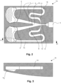
- the oscillator 1a of figures 1 to 3 is a traditional fluidic oscillator, of which the air outlets 2,3 are provided with perforated plates 4 with fifty round holes of 1.7mm diameter each.
- This oscillator 1a is further called the first oscillator and does not form part of the invention.
- the first oscillator 1a comprises a first air inlet 5 and an air inlet channel 6 leading away from the first air inlet 5.
- the air inlet channel 6 widens and diverges into two air outlet channels, more specifically a first outlet channel 7 and a second outlet channel 8 which lead to the two aforementioned air outlets 2,3, more specifically to a first air outlet 2 and to a second air outlet 3, which are provided with said perforated plates 4.
- the two outlet channels 7, 8 are separated by a splitter 9 with a concave nose 10.
- the splitter 9 and the air inlet channel 6 and the outlet channels 7, 8 jointly constitute a bistable fluidic amplifier arranged to amplify control signals, whereby in this case the control signals are fed to the fluidic amplifier via a first control port 11 and a second control port 12.
- a feedback channel 13 leads back to the control ports at the point where the air inlet channel 6 widens.
- the first oscillator 1a works as follows: A constant airflow is established at the first air inlet 5 and through the air inlet channel 6. This airflow will either flow through the first outlet channel 7 or through the second outlet channel 8, but not through both at the same time. If undisturbed, the air will continue to flow this way because of the Coanda-effect, which enhances the tendency for a fluid to follow a curved surface.
- the transition from the air inlet channel 6 to each of the outlet channels 7, 8 is such a curved surface.
- the concave nose 10 of the splitter 9 helps to create an induced secondary airflow that further stabilises the airflow through that particular outlet channel 7,8.
- a sequence of pressure control signals in other words a pressure control wave, is established at both control ports 11, 12, every time switching the airflow from the first outlet channel 7 to the second outlet channel 8 and back, thereby generating two pulsating airflows, one in each of the outlet channels 7, 8, each pulsating with the same oscillation frequency and phase shifted by half a wave period.
- the oscillation frequency of the first oscillator 1a is more or less fixed, depending on the exact design of the first oscillator 1a.
- a change in air pressure at the first air inlet 5, resulting in a change in the total air flow rate through the first oscillator 1a, will influence the oscillation frequency to a relatively small degree, but the oscillation frequency can not be controlled independently of the air flow rate
- a second oscillator 1b differs mainly from the traditional oscillator in that there are no feedback channels 13 and no control ports 11, 12. Consequently, the outer contours of the housing of the second oscillator 1b can be much smaller.
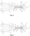
- the second oscillator 1b is instead provided with two piezo-electric bender actuators 15, which are extending in the length direction of the air inlet channel 6 and which are fixedly attached at one of their extremes 17a, near the first air inlet 5.
- the actuators 15 are each connected to a source of alternating voltage, with a controllable frequency, via electrical wires which are not shown in the figures, but which run via wire channels 16 provided in the housing of the second oscillator 1b.
- the actuators 15 can bend in two directions, depending on whether a positive or a negative voltage is applied to them. This results in a movement of the free extreme 17b of the actuators 15, so that the actuators 15 can adopt two working positions, one of which is shown in figure 4 , and the other of which is shown in figure 5 .
- the housing of the second oscillator 1b is provided with matching recesses 18.
- the actuators 15 constitute at least part of the wall of the air inlet channel 6.
- the second oscillator 1b works as follows: Like for the first oscillator 1a, a constant airflow is established at the first air inlet 5 and through the air inlet channel 6, with the actuators 15 in their neutral position. This airflow through the air inlet channel 6 establishes itself in a stable flow pattern into either the first outlet channel 7 or the second outlet channel 8, and then onward towards the corresponding air outlet 2,3.
- Oscillation of the airflow through the second oscillator 1b is induced by applying an alternating voltage to the actuators 15. These actuators 15 will then alternatingly switch between the two working positions. A movement of the actuators 15 in one direction, eg from the working position shown in fig.4 to the working position shown in fig. 5 , will then cause the airflow to switch from the first outlet channel 7 to the second outlet channel 8, and therefore constitutes a first mechanical control signal for such a switch.
- a repeated movement of the actuators 15 thereby generates a control wave of a mechanical-energy signal, which is amplified by the fluidic amplifier, every time switching the airflow from the first outlet channel 7 to the second outlet channel 8 and back, thereby generating two pulsating airflows, one in each of the outlet channels 7, 8, each pulsating with the same oscillation frequency and phase-shifted by half a wave period.
- the actuators 15 are directing the airflow from the first air inlet 5 channel towards one of the two outlet channels 7, 8, once the airflow is established in one of two outlet channels 7, 8, the actuators 15 are not needed anymore to maintain this airflow. Due to the Coanda-effect this airflow will remain stable even if the actuators 15 would be absent.
- both actuators 15 should be actuating at the same frequency. They do not necessarily need to operate exactly in phase, as, depending on the situation, a faster or slower switch from an airflow in one outlet channel 7,8 to an airflow in the other outlet channel 7,8 may be required and can be obtained by making one of the actuators 15 move slightly earlier than the other actuator 15.
- the oscillation frequency of the second oscillator 1b will be the same as the frequency of the alternating voltage. This oscillation frequency can therefore be easily controlled by electronically altering the frequency of the alternating voltage. This can be done independently of the actual airflow through the second oscillator 1b.
- a third oscillator 1c differs from the first oscillator 1a in that the feedback channels are absent. There are however, like in the first oscillator 1a, two control ports 11, 12 present in the air inlet channel 6. This part of the third oscillator 1c is essentially a traditional bistable fluidic amplifier with control ports 11, 12, and is not shown separately.
- the third oscillator 1c comprises a pressure wave generator 19, shown in figs. 6 and 7 , for generating a control signal.
- This pressure wave generator 19 comprises a second air inlet 20, which splits at a junction 21 into a first control channel 22 and a second control channel 23.
- a cavity 24 is present on the opposite side of the junction 21, compared to the second air inlet 20, a cavity 24 is present.
- a single piezo-electric bender actuator 15 is fixedly attached at one of its extremes 17a.
- the other, free, extreme 17b of the actuator 15 extends into the junction 21, and is provided with an approximately triangular valve member 25.
- the first control channel 22 is connected to the first control port 11 and the second control channel 23 is connected to the second control port 12 of the bistable fluidic amplifier.
- the actuator 15 is connected to a source of alternating voltage with a controllable frequency, via electrical wires which are not shown in the figures, but which run via a wire channel 16 provided in the housing of the pressure wave generator 19.
- the actuator 15 can bend in two directions, depending on whether a positive or a negative voltage is applied to it, and can thereby adopt two working positions, one of which is shown in figure 6 , and the other of which is shown in figure 7 . It will be clear that in case no voltage is applied, the actuator 15 adopts a neutral position, intermediate between these two working positions.
- the third oscillator 1c works as follows: Like for the first oscillator 1a, a constant airflow is established at the first air inlet 5 and through the air inlet channel 6. This airflow through the air inlet channel 6 then establishes itself, like in the first oscillator 1a, in a stable flow pattern into either the first outlet channel 7 or the second outlet channel 8 due to the Coanda-effect, and then onward towards the corresponding air outlet 2,3.
- a constant airflow is also established at the second air inlet 20, which is the air inlet of the pressure wave generator 9. This constant airflow is much smaller than the airflow through the air inlet channel 6 and is less than 10% of the airflow through the air inlet channel 6. This second airflow will be used to generate two control pressure wave signals which are fed to the control ports 11, 12.
- This actuator 15 will then alternatingly switch between the two working positions.
- a movement of the actuator 15 in one direction eg from the working position shown in fig.6 to the working position shown in fig. 7 , will cause the second control channel 23 to become blocked at the junction 21, so that the airflow from the second air inlet 20 will exclusively flow into the first control channel 22 and thereby cause a pressure signal in the first control channel 22.
- control channels 22, 23 do not necessarily need to become totally blocked. Partial blocking of the control channels 22, 23, so that the majority, preferably at least 67%, of the air will flow into the other control channel 22,23, is sufficient, although not optimal.
- a repeated movement of the actuator 15 thereby generates two pressure wave control signals, one in the first control channel 22 and one in the second control channel 23, whereby these pressure waves are phase-shifted by half a wave period.
- first control channel 22 is connected to the first control port 11 and the second control channel 23 is connected to the second control port 12 a pressure signal in the first control channel 22 causes the airflow in the air inlet channel 6 to flow into the second outlet channel 8 and so towards the second air outlet 3.
- a pressure signal in the second control channel 23 causes the airflow in the first air inlet 5 channel to flow into first outlet channel 7 and so towards the first air outlet 2.
- control waves of pressure signals in the control channels 22, 23 are amplified by the fluidic amplifier in the third oscillator 1c, every time switching the airflow from the first outlet channel 7 to the second outlet channel 8 and back, thereby generating two pulsating airflows, one in each of the outlet channels 7, 8, each pulsating with the same oscillation frequency and phase-shifted by half a wave period.
- the oscillation frequency of the third oscillator 1c will be the same as the frequency of the alternating voltage. This oscillation frequency can therefore be easily controlled by electronically altering the frequency of the alternating voltage. This can be done independently of the actual airflow through the third oscillator 1c.
- An advantageous way of using the first, second and third oscillators is in a method of generating a bubble screen to reduce the propagation of underwater sound by attenuating the sound energy of this sound, which is desirable to limit the effects of construction works on animals in the water.
- a third oscillator 1c can also be used instead of the second oscillator 1b without adaptations.
- a first oscillator 1a can also be used with some limitations, as will be described below.
- figures 8 and 9 are schematic representations and are not to scale.
- a device 30 is shown for attenuation of sound energy, in other words for reducing underwater sound propagation, originating from a source 29 of underwater sound,eg offshore/inland water construction activities, such as pile driving for building constructions or platforms.
- the device 30 comprises a flexible air hose 31, to which bubble generation units 32 are connected.
- the air hose 31 is connected to a source 33 of pressurized air.
- the bubble generation units 32 are arranged in a circle with a radius of circa 50 m around a source 29 of underwater sound, for instance a pile-driving activity.
- the bubble generation units 32 have a footprint of circa 50 cm by 100 cm, and contain two parallel rows 34a, 34b, on either side of the air hose 31, of eight identical oscillators 1b per row 34a, 34b.
- each of the bubble generation units 32 comprises a bubble generation unit body 35, typically made of rubber, in which for each oscillator a channel 36, running from close to the base of the bubble generation unit body 35 to the top of the bubble generation unit body 35, is provided.
- the device further comprises a control unit 37.
- the control unit 37 will usually be mounted on a ship, which is not shown in the figures.
- the control unit 37 is connected to the piezo-electric actuators 15 of the oscillators and is arranged to supply an alternating voltage to these actuators 15, via a cable channel 38.
- the device 30 is set up such that separate connections for applying an alternating voltage from the control unit 37 to the separate rows of oscillators are present, so that an alternating voltage with a different frequency can be supplied to the piezo-electric actuators 15 of the oscillators in the respective rows.
- the device 30 further comprises a hydrophone 39 which is connected to the control unit 37 and which is positioned outside the circle formed by the air hose 31.
- the control unit 37 is programmed to analyse a sound frequency spectrum captured by the hydrophone 39 and to determine the dominant frequency or frequencies in this sound frequency spectrum.
- the use of the device 30 in a method for attenuating sound energy or reducing sound propagation under water is as follows.
- pressurized air is supplied to the air hose 31 and an alternating voltage with a certain starting frequency is supplied by the control unit 37 to the oscillators 1b.
- the oscillators 1b will oscillate at that same frequency, and generate air pulses at the air outlets 2,3.
- air bubbles 40 are thereby generated in the channels 36.
- the air bubbles 40 will start to move up, acting as an air pump and establishing an upward water flow in the channels 36, as indicated by the arrows A in figure 10 .
- This water flow will effectively remove newly forming air bubbles 40 at the holes in the perforated plates 4, so that an equilibrium situation with a constant air bubble 40 size is quickly established.
- These air bubbles 40 are released from the channels 36 in the bubble generation unit body 35, so that these channels 36 in effect become a bubble outlet channel 36.
- the hydrophone 39 captures the sound spectrum of the underwater sound outside the circle, so the sound spectrum of the underwater sound not absorbed or reflected by the air bubbles 40 in the bubble screen.
- This sound spectrum which is analysed by the control unit 37 by means of fast fourier transform so that the sound frequency or frequencies having the highest sound pressure can be established.
- control unit 37 can actively adapt the frequency of the alternating voltage supplied to the oscillators 1b, and thereby the oscillation frequencies of the oscillators 1b, and thereby the size of the air bubbles 40 generated, in order to achieve a maximum reduction of the propagation of the underwater sound.
- a first oscillator 1a is usable in the bubble generation units 32.
- the air bubble size will then not be controllable and adjustable, but the advantage of obtaining a constant and stable flow of air bubbles 40 of a constant size out of such a bubble generation unit 32 is nevertheless present, compared to air bubbles created by random phenomena, such as occur when air is pressed out of a standard hole or nozzle, which will vary in size and in mutual distance.
- a bubble generation unit 32 having a first oscillator 1a can firstly be better designed than traditional bubble generation units to generate air bubble sizes matching the sound frequency spectrum expected from specific underwater noise-generating activities. Secondly, such air bubbles 40 will coalesce less compared to air bubbles coming out of traditional bubble generation units, so that they remain active and effective longer, in other words over a greater vertical distance as they rise through the water.
- two, or even more, of such devices 30 can be used together, either or not supplied with pressurized air from the same source 33.
- a second device 30 is placed in a circle around a first device 30.
- the oscillators 1b in the bubble generation units 32 of the second device 30 will usually work at a different oscillation frequency than the oscillators 1b in the bubble generation units 32 of the first device 30, thereby generating different bubble sizes in the inner bubble screen than in the outer bubble screen.
- both devices 30 comprise a separate hydrophone located on the other side of the respective bubble screen compared to the source of underwater sound , so that the performance of both devices 30 can be optimized independently for greater overall performance.
- first, second and third oscillators 1a,1b,1c are useful applications of the first, second and third oscillators 1a,1b,1c, either for optimising physical phenomena, such as gas-liquid or liquid-liquid material transfer, eg. by diffusion, or chemical phenomena, such as gas-liquid or liquid-liquid chemical reactions.
Landscapes
- Engineering & Computer Science (AREA)
- Physics & Mathematics (AREA)
- Civil Engineering (AREA)
- Multimedia (AREA)
- Life Sciences & Earth Sciences (AREA)
- General Life Sciences & Earth Sciences (AREA)
- Mining & Mineral Resources (AREA)
- Paleontology (AREA)
- Acoustics & Sound (AREA)
- General Engineering & Computer Science (AREA)
- Structural Engineering (AREA)
- Chemical & Material Sciences (AREA)
- Aviation & Aerospace Engineering (AREA)
- Combustion & Propulsion (AREA)
- Fluid Mechanics (AREA)
- Apparatuses For Generation Of Mechanical Vibrations (AREA)
- Soundproofing, Sound Blocking, And Sound Damping (AREA)
- Measurement Of Velocity Or Position Using Acoustic Or Ultrasonic Waves (AREA)
- Electrostatic, Electromagnetic, Magneto- Strictive, And Variable-Resistance Transducers (AREA)
Claims (13)
- Dispositif (30) configuré pour atténuer la pression acoustique sous-marine, moyennant quoi le dispositif (30) comprend au moins une unité de génération de bulles (32) et un conduit d'air (31) permettant d'alimenter de l'air sous pression à l'unité de génération de bulles (32), dans lequel l'unité de génération de bulles (32) comprend un oscillateur fluidique (1b, 1c) permettant de générer un ou plusieurs flux d'air pulsé à partir d'un flux d'air constant, dans lequel l'oscillateur est un oscillateur (1b, 1c) ayant une fréquence d'oscillation réglable, moyennant quoi la fréquence d'oscillation de l'oscillateur (1b, 1c) est réglable indépendamment de la pression d'air dans le conduit d'air (31), caractérisé en ce que le dispositif (30) comprend un moyen de capture de son (38) et une unité de commande (37), moyennant quoi l'unité de commande (37) est agencée pour recevoir un signal d'entrée du moyen de capture de son (38) et pour envoyer à l'oscillateur (1b, 1c) un signal de commande pour commander la fréquence d'oscillation, moyennant quoi l'unité de commande (37) est agencée pour calculer le signal de commande en utilisant le signal d'entrée.
- Dispositif (30) selon la revendication 1, caractérisé en ce que l'unité de commande (37) est agencée pour calculer une distribution de fréquence acoustique à partir du signal d'entrée, moyennant quoi l'unité de commande (37) est agencée pour calculer le signal de commande à partir de la distribution de fréquence sonore.
- Dispositif (30) selon l'une quelconque des revendications précédentes, caractérisé en ce que le dispositif (30) comprend un premier type dudit oscillateur (1b, 1c) et un deuxième type dudit oscillateur (1b, 1c), moyennant quoi le premier type dudit oscillateur (1b, 1c) et le deuxième type dudit oscillateur (1b, 1c) sont conçus pour fonctionner à différentes fréquences d'oscillation s'ils sont alimentés avec de l'air à la même pression.
- Dispositif (30) selon l'une quelconque des revendications précédentes, caractérisé en ce que le conduit d'air est un tuyau d'air flexible (31), moyennant quoi le dispositif (30) comprend une pluralité desdites unités de génération de bulles (32) agencées le long d'au moins une partie de la longueur dudit tuyau d'air (31).
- Dispositif (30) selon l'une quelconque des revendications précédentes, caractérisé en ce que l'unité de génération de bulles (32) comprend un corps d'unité de génération de bulles (35) comportant un canal de sortie de bulles (36) qui est ouvert à son extrémité supérieure et à son extrémité inférieure, moyennant quoi l'oscillateur (1b, 1c) comprend une sortie d'air qui débouche dans le canal de sortie de bulles (36).
- Dispositif (30) selon l'une quelconque des revendications précédentes, caractérisé en ce que l'oscillateur (1b, 1c) comprend au moins deux sorties d'air séparées (2, 3) fonctionnant à la même fréquence, mais avec un décalage de phase d'une demi période d'onde.
- Utilisation d'un dispositif (30) selon l'une quelconque des revendications précédentes pour atténuer l'énergie sonore d'un bruit sous-marin, moyennant quoi le conduit d'air (31) et l'unité de génération de bulles (32) sont placés sous l'eau, moyennant quoi de l'air sous pression est fourni au conduit d'air (31) et moyennant quoi des bulles d'air (40) sont générées par l'unité de génération de bulles (32).
- Utilisation selon la revendication 7, caractérisée en ce que le conduit d'air (31) ou les conduits d'air (31) d'un ou plusieurs tels dispositifs encerclent une source de bruit sous-marin, moyennant quoi le dispositif (30) comprend au moins quatre unités de génération de bulles (32) qui sont placées sous l'eau.
- Utilisation selon les revendications 7 ou 8, caractérisée en ce que le dispositif (30) est un dispositif (30) selon les revendications 3 ou 4, moyennant quoi le moyen de capture de son (38) est placé sous l'eau, moyennant quoi le conduit d'air (31) est placé entre le moyen de capture de son (38) et une source (29) de bruit sous-marin.
- Utilisation selon la revendication 9, caractérisée en ce que l'unité de commande (37) commande la fréquence d'oscillation de l'oscillateur (1b, 1c) en fonction de la distribution de fréquence du son capturé par le moyen de capture de son (38).
- Utilisation selon l'une quelconque des revendications 7 à 10, caractérisée en ce que le dispositif (30) comprend au moins deux oscillateurs (1b, 1c) ayant chacun une fréquence d'oscillation réglable, moyennant quoi les au moins deux oscillateurs (1b 1c) sont alimentés avec de l'air provenant du même conduit d'air (31), moyennant quoi un premier oscillateur desdits oscillateurs (1b, 1c) est commandé pour fonctionner à une première fréquence d'oscillation, moyennant quoi un deuxième oscillateur desdits oscillateurs (1b, 1c) est commandé pour fonctionner à une deuxième fréquence d'oscillation.
- Utilisation selon l'une quelconque des revendications 7 à 11, moyennant laquelle un premier dispositif (30) et un deuxième dispositif (30), tous deux selon l'une quelconque des revendications 1 à 8, sont utilisés, moyennant quoi le conduit d'air (31) du premier dispositif (30) forme au moins une partie d'un encerclement d'une source (29) de bruit sous-marin, moyennant quoi le conduit d'air (31) du deuxième dispositif (30) forme au moins une partie d'un encerclement du conduit d'air (31) du premier dispositif (30).
- Utilisation selon l'une quelconque des revendications 7 à 12, caractérisée en ce que l'unité de génération de bulles (32) du premier dispositif (30) génère des bulles (40) d'une taille différente de celles de l'unité de génération de bulles (32) du deuxième dispositif (30).
Applications Claiming Priority (2)
| Application Number | Priority Date | Filing Date | Title |
|---|---|---|---|
| EP20170186.9A EP3896685A1 (fr) | 2020-04-17 | 2020-04-17 | Dispositif permettant d'atténuer la pression sonore sous-marine et utilisation d'un tel dispositif |
| PCT/EP2021/060033 WO2021209638A1 (fr) | 2020-04-17 | 2021-04-19 | Dispositif d'atténuation de la pression sonore sous-marine et utilisation d'un tel dispositif |
Publications (2)
| Publication Number | Publication Date |
|---|---|
| EP4136636A1 EP4136636A1 (fr) | 2023-02-22 |
| EP4136636B1 true EP4136636B1 (fr) | 2024-07-17 |
Family
ID=70333778
Family Applications (2)
| Application Number | Title | Priority Date | Filing Date |
|---|---|---|---|
| EP20170186.9A Withdrawn EP3896685A1 (fr) | 2020-04-17 | 2020-04-17 | Dispositif permettant d'atténuer la pression sonore sous-marine et utilisation d'un tel dispositif |
| EP21719908.2A Active EP4136636B1 (fr) | 2020-04-17 | 2021-04-19 | Dispositif permettant d'atténuer la pression sonore sous-marine et utilisation d'un tel dispositif |
Family Applications Before (1)
| Application Number | Title | Priority Date | Filing Date |
|---|---|---|---|
| EP20170186.9A Withdrawn EP3896685A1 (fr) | 2020-04-17 | 2020-04-17 | Dispositif permettant d'atténuer la pression sonore sous-marine et utilisation d'un tel dispositif |
Country Status (7)
| Country | Link |
|---|---|
| US (1) | US12209377B2 (fr) |
| EP (2) | EP3896685A1 (fr) |
| JP (1) | JP7592749B2 (fr) |
| KR (1) | KR20220167382A (fr) |
| CN (1) | CN115715412A (fr) |
| CA (1) | CA3175378A1 (fr) |
| WO (1) | WO2021209638A1 (fr) |
Families Citing this family (4)
| Publication number | Priority date | Publication date | Assignee | Title |
|---|---|---|---|---|
| CN116320887B (zh) * | 2023-03-24 | 2025-07-18 | 厦门大学 | 一种仿江豚的水声接收装置 |
| CN117190301A (zh) * | 2023-09-01 | 2023-12-08 | 珠海格力节能环保制冷技术研究中心有限公司 | 新风出风装置及空调器 |
| WO2025226995A1 (fr) * | 2024-04-26 | 2025-10-30 | Chevron U.S.A. Inc. | Réseau de résonateurs en eau profonde avec distribution de gravité |
| CN120001234B (zh) * | 2025-04-16 | 2025-06-20 | 中南大学 | 一种两相振荡射流微纳米气泡发生器及使用方法 |
Family Cites Families (11)
| Publication number | Priority date | Publication date | Assignee | Title |
|---|---|---|---|---|
| JPH0618131Y2 (ja) * | 1986-09-04 | 1994-05-11 | 石川島播磨重工業株式会社 | 水中伝播音減衰装置 |
| US6571906B2 (en) * | 2001-08-20 | 2003-06-03 | The United States Of America As Represented By The Secretary Of The Navy | Underwater sound mitigation system for explosive testing |
| GB2443396B (en) * | 2006-10-30 | 2011-10-19 | Univ Sheffield | Bubble generation for aeration and other purposes |
| WO2010056984A2 (fr) * | 2008-11-14 | 2010-05-20 | The Regents Of The University Of Michigan | Mécanisme de régulation acoustique de fluide |
| GB2466664B (en) * | 2009-01-06 | 2015-04-01 | Perlemax Ltd | Plasma microreactor apparatus, sterilisation unit and analyser |
| DK201070283A (en) | 2010-06-22 | 2012-02-02 | Maersk Olie & Gas | Reducing drag of a hull of a ship |
| WO2013061276A1 (fr) * | 2011-10-27 | 2013-05-02 | Ramot At Tel-Aviv University Ltd. | Synchronisation d'actionneurs fluidiques |
| RU2696974C2 (ru) * | 2015-01-15 | 2019-08-08 | Дженерал Фьюжн Инк. | Устройство и способ создания вихревой воронки во вращающейся текучей среде |
| CN206921468U (zh) * | 2017-06-20 | 2018-01-23 | 屈科 | 在水下用气泡帷幕阻挡声音传播的装置 |
| GB201905126D0 (en) * | 2019-04-11 | 2019-05-29 | Perlemax Ltd | Fluidic oscilators |
| US11865556B2 (en) * | 2019-05-29 | 2024-01-09 | Ohio State Innovation Foundation | Out-of-plane curved fluidic oscillator |
-
2020
- 2020-04-17 EP EP20170186.9A patent/EP3896685A1/fr not_active Withdrawn
-
2021
- 2021-04-19 CN CN202180042779.1A patent/CN115715412A/zh active Pending
- 2021-04-19 WO PCT/EP2021/060033 patent/WO2021209638A1/fr not_active Ceased
- 2021-04-19 US US17/918,639 patent/US12209377B2/en active Active
- 2021-04-19 EP EP21719908.2A patent/EP4136636B1/fr active Active
- 2021-04-19 CA CA3175378A patent/CA3175378A1/fr active Pending
- 2021-04-19 KR KR1020227039400A patent/KR20220167382A/ko active Pending
- 2021-04-19 JP JP2022562756A patent/JP7592749B2/ja active Active
Also Published As
| Publication number | Publication date |
|---|---|
| US20230349122A1 (en) | 2023-11-02 |
| KR20220167382A (ko) | 2022-12-20 |
| EP4136636A1 (fr) | 2023-02-22 |
| CN115715412A (zh) | 2023-02-24 |
| EP3896685A1 (fr) | 2021-10-20 |
| CA3175378A1 (fr) | 2021-10-21 |
| JP7592749B2 (ja) | 2024-12-02 |
| JP2023529537A (ja) | 2023-07-11 |
| WO2021209638A1 (fr) | 2021-10-21 |
| US12209377B2 (en) | 2025-01-28 |
Similar Documents
| Publication | Publication Date | Title |
|---|---|---|
| EP4136636B1 (fr) | Dispositif permettant d'atténuer la pression sonore sous-marine et utilisation d'un tel dispositif | |
| US4681264A (en) | Enhancing liquid jet erosion | |
| CA1151073A (fr) | Oscillateur fluidique a circuit resonant a inertance et a compliance dynamique | |
| US3741481A (en) | Shower spray | |
| CA1103128A (fr) | Gicleurs a commande hydraulique pour engendrer des vibrations dans des volumes de liquides | |
| JP3020290B2 (ja) | 流体の流れを遮断する為の方法と装置 | |
| KR890702000A (ko) | 잉크젯트배열 | |
| AU705492B2 (en) | Gas dissolution in liquids | |
| US4127950A (en) | Bottom jetting device | |
| AU4937793A (en) | Method and apparatus for generating high energy acoustic pulses | |
| EP3895792B1 (fr) | Oscillateur pour générer au moins deux écoulements de fluide pulsés à partir d'un écoulement de fluide constant et procédé de génération de bulles de fluide dans un liquide | |
| HK40085060A (en) | Device for attenuating underwater sound pressure and the use of such a device | |
| JPH10245834A (ja) | クラゲ流入防止装置 | |
| WO2002004288A1 (fr) | Outil de nettoyage sous-aquatique de surfaces et buse pour outil de nettoyage | |
| US3083664A (en) | Ship sound simulator | |
| JPS5768214A (en) | Cooling water supply system for steel material | |
| JPH10280369A (ja) | クラゲ流入防止装置 | |
| KR100275262B1 (ko) | 헤름홀츠(Helmholtz)공명원리를 이용한 해수 교환형 방파제 | |
| JP2005180110A (ja) | 河川の水流を利用した淀み防止方法 | |
| RU2163169C2 (ru) | Душевая насадка | |
| RU1800133C (ru) | Жидкостно-газовый эжектор | |
| EP4476130A1 (fr) | Procédé de fourniture d'une coque d'un navire ayant des générateurs de bulles | |
| JPS6334250B2 (fr) | ||
| KR20140064315A (ko) | 마찰저항 감소장치를 포함하는 선박 | |
| JPH0734428A (ja) | 消波堤 |
Legal Events
| Date | Code | Title | Description |
|---|---|---|---|
| STAA | Information on the status of an ep patent application or granted ep patent |
Free format text: STATUS: UNKNOWN |
|
| STAA | Information on the status of an ep patent application or granted ep patent |
Free format text: STATUS: THE INTERNATIONAL PUBLICATION HAS BEEN MADE |
|
| PUAI | Public reference made under article 153(3) epc to a published international application that has entered the european phase |
Free format text: ORIGINAL CODE: 0009012 |
|
| STAA | Information on the status of an ep patent application or granted ep patent |
Free format text: STATUS: REQUEST FOR EXAMINATION WAS MADE |
|
| 17P | Request for examination filed |
Effective date: 20221110 |
|
| AK | Designated contracting states |
Kind code of ref document: A1 Designated state(s): AL AT BE BG CH CY CZ DE DK EE ES FI FR GB GR HR HU IE IS IT LI LT LU LV MC MK MT NL NO PL PT RO RS SE SI SK SM TR |
|
| DAV | Request for validation of the european patent (deleted) | ||
| DAX | Request for extension of the european patent (deleted) | ||
| RAP3 | Party data changed (applicant data changed or rights of an application transferred) |
Owner name: ALFA LAVAL ROTTERDAM B.V. |
|
| GRAP | Despatch of communication of intention to grant a patent |
Free format text: ORIGINAL CODE: EPIDOSNIGR1 |
|
| STAA | Information on the status of an ep patent application or granted ep patent |
Free format text: STATUS: GRANT OF PATENT IS INTENDED |
|
| INTG | Intention to grant announced |
Effective date: 20240411 |
|
| GRAS | Grant fee paid |
Free format text: ORIGINAL CODE: EPIDOSNIGR3 |
|
| GRAA | (expected) grant |
Free format text: ORIGINAL CODE: 0009210 |
|
| STAA | Information on the status of an ep patent application or granted ep patent |
Free format text: STATUS: THE PATENT HAS BEEN GRANTED |
|
| P01 | Opt-out of the competence of the unified patent court (upc) registered |
Free format text: CASE NUMBER: APP_33714/2024 Effective date: 20240605 |
|
| AK | Designated contracting states |
Kind code of ref document: B1 Designated state(s): AL AT BE BG CH CY CZ DE DK EE ES FI FR GB GR HR HU IE IS IT LI LT LU LV MC MK MT NL NO PL PT RO RS SE SI SK SM TR |
|
| REG | Reference to a national code |
Ref country code: CH Ref legal event code: EP |
|
| REG | Reference to a national code |
Ref country code: DE Ref legal event code: R096 Ref document number: 602021015830 Country of ref document: DE |
|
| REG | Reference to a national code |
Ref country code: IE Ref legal event code: FG4D |
|
| REG | Reference to a national code |
Ref country code: LT Ref legal event code: MG9D |
|
| REG | Reference to a national code |
Ref country code: NL Ref legal event code: MP Effective date: 20240717 |
|
| REG | Reference to a national code |
Ref country code: GR Ref legal event code: EP Ref document number: 20240402191 Country of ref document: GR Effective date: 20241111 |
|
| PG25 | Lapsed in a contracting state [announced via postgrant information from national office to epo] |
Ref country code: PT Free format text: LAPSE BECAUSE OF FAILURE TO SUBMIT A TRANSLATION OF THE DESCRIPTION OR TO PAY THE FEE WITHIN THE PRESCRIBED TIME-LIMIT Effective date: 20241118 |
|
| REG | Reference to a national code |
Ref country code: AT Ref legal event code: MK05 Ref document number: 1704916 Country of ref document: AT Kind code of ref document: T Effective date: 20240717 |
|
| PG25 | Lapsed in a contracting state [announced via postgrant information from national office to epo] |
Ref country code: NL Free format text: LAPSE BECAUSE OF FAILURE TO SUBMIT A TRANSLATION OF THE DESCRIPTION OR TO PAY THE FEE WITHIN THE PRESCRIBED TIME-LIMIT Effective date: 20240717 |
|
| PG25 | Lapsed in a contracting state [announced via postgrant information from national office to epo] |
Ref country code: PT Free format text: LAPSE BECAUSE OF FAILURE TO SUBMIT A TRANSLATION OF THE DESCRIPTION OR TO PAY THE FEE WITHIN THE PRESCRIBED TIME-LIMIT Effective date: 20241118 Ref country code: NL Free format text: LAPSE BECAUSE OF FAILURE TO SUBMIT A TRANSLATION OF THE DESCRIPTION OR TO PAY THE FEE WITHIN THE PRESCRIBED TIME-LIMIT Effective date: 20240717 |
|
| PG25 | Lapsed in a contracting state [announced via postgrant information from national office to epo] |
Ref country code: FI Free format text: LAPSE BECAUSE OF FAILURE TO SUBMIT A TRANSLATION OF THE DESCRIPTION OR TO PAY THE FEE WITHIN THE PRESCRIBED TIME-LIMIT Effective date: 20240717 Ref country code: PL Free format text: LAPSE BECAUSE OF FAILURE TO SUBMIT A TRANSLATION OF THE DESCRIPTION OR TO PAY THE FEE WITHIN THE PRESCRIBED TIME-LIMIT Effective date: 20240717 |
|
| PG25 | Lapsed in a contracting state [announced via postgrant information from national office to epo] |
Ref country code: BG Free format text: LAPSE BECAUSE OF FAILURE TO SUBMIT A TRANSLATION OF THE DESCRIPTION OR TO PAY THE FEE WITHIN THE PRESCRIBED TIME-LIMIT Effective date: 20240717 |
|
| PG25 | Lapsed in a contracting state [announced via postgrant information from national office to epo] |
Ref country code: LV Free format text: LAPSE BECAUSE OF FAILURE TO SUBMIT A TRANSLATION OF THE DESCRIPTION OR TO PAY THE FEE WITHIN THE PRESCRIBED TIME-LIMIT Effective date: 20240717 |
|
| PG25 | Lapsed in a contracting state [announced via postgrant information from national office to epo] |
Ref country code: AT Free format text: LAPSE BECAUSE OF FAILURE TO SUBMIT A TRANSLATION OF THE DESCRIPTION OR TO PAY THE FEE WITHIN THE PRESCRIBED TIME-LIMIT Effective date: 20240717 Ref country code: IS Free format text: LAPSE BECAUSE OF FAILURE TO SUBMIT A TRANSLATION OF THE DESCRIPTION OR TO PAY THE FEE WITHIN THE PRESCRIBED TIME-LIMIT Effective date: 20241117 |
|
| PG25 | Lapsed in a contracting state [announced via postgrant information from national office to epo] |
Ref country code: HR Free format text: LAPSE BECAUSE OF FAILURE TO SUBMIT A TRANSLATION OF THE DESCRIPTION OR TO PAY THE FEE WITHIN THE PRESCRIBED TIME-LIMIT Effective date: 20240717 |
|
| PG25 | Lapsed in a contracting state [announced via postgrant information from national office to epo] |
Ref country code: ES Free format text: LAPSE BECAUSE OF FAILURE TO SUBMIT A TRANSLATION OF THE DESCRIPTION OR TO PAY THE FEE WITHIN THE PRESCRIBED TIME-LIMIT Effective date: 20240717 Ref country code: RS Free format text: LAPSE BECAUSE OF FAILURE TO SUBMIT A TRANSLATION OF THE DESCRIPTION OR TO PAY THE FEE WITHIN THE PRESCRIBED TIME-LIMIT Effective date: 20241017 |
|
| PG25 | Lapsed in a contracting state [announced via postgrant information from national office to epo] |
Ref country code: RS Free format text: LAPSE BECAUSE OF FAILURE TO SUBMIT A TRANSLATION OF THE DESCRIPTION OR TO PAY THE FEE WITHIN THE PRESCRIBED TIME-LIMIT Effective date: 20241017 Ref country code: PL Free format text: LAPSE BECAUSE OF FAILURE TO SUBMIT A TRANSLATION OF THE DESCRIPTION OR TO PAY THE FEE WITHIN THE PRESCRIBED TIME-LIMIT Effective date: 20240717 Ref country code: LV Free format text: LAPSE BECAUSE OF FAILURE TO SUBMIT A TRANSLATION OF THE DESCRIPTION OR TO PAY THE FEE WITHIN THE PRESCRIBED TIME-LIMIT Effective date: 20240717 Ref country code: IS Free format text: LAPSE BECAUSE OF FAILURE TO SUBMIT A TRANSLATION OF THE DESCRIPTION OR TO PAY THE FEE WITHIN THE PRESCRIBED TIME-LIMIT Effective date: 20241117 Ref country code: HR Free format text: LAPSE BECAUSE OF FAILURE TO SUBMIT A TRANSLATION OF THE DESCRIPTION OR TO PAY THE FEE WITHIN THE PRESCRIBED TIME-LIMIT Effective date: 20240717 Ref country code: FI Free format text: LAPSE BECAUSE OF FAILURE TO SUBMIT A TRANSLATION OF THE DESCRIPTION OR TO PAY THE FEE WITHIN THE PRESCRIBED TIME-LIMIT Effective date: 20240717 Ref country code: ES Free format text: LAPSE BECAUSE OF FAILURE TO SUBMIT A TRANSLATION OF THE DESCRIPTION OR TO PAY THE FEE WITHIN THE PRESCRIBED TIME-LIMIT Effective date: 20240717 Ref country code: BG Free format text: LAPSE BECAUSE OF FAILURE TO SUBMIT A TRANSLATION OF THE DESCRIPTION OR TO PAY THE FEE WITHIN THE PRESCRIBED TIME-LIMIT Effective date: 20240717 Ref country code: AT Free format text: LAPSE BECAUSE OF FAILURE TO SUBMIT A TRANSLATION OF THE DESCRIPTION OR TO PAY THE FEE WITHIN THE PRESCRIBED TIME-LIMIT Effective date: 20240717 |
|
| PG25 | Lapsed in a contracting state [announced via postgrant information from national office to epo] |
Ref country code: SM Free format text: LAPSE BECAUSE OF FAILURE TO SUBMIT A TRANSLATION OF THE DESCRIPTION OR TO PAY THE FEE WITHIN THE PRESCRIBED TIME-LIMIT Effective date: 20240717 Ref country code: DK Free format text: LAPSE BECAUSE OF FAILURE TO SUBMIT A TRANSLATION OF THE DESCRIPTION OR TO PAY THE FEE WITHIN THE PRESCRIBED TIME-LIMIT Effective date: 20240717 Ref country code: RO Free format text: LAPSE BECAUSE OF FAILURE TO SUBMIT A TRANSLATION OF THE DESCRIPTION OR TO PAY THE FEE WITHIN THE PRESCRIBED TIME-LIMIT Effective date: 20240717 |
|
| REG | Reference to a national code |
Ref country code: DE Ref legal event code: R097 Ref document number: 602021015830 Country of ref document: DE |
|
| PG25 | Lapsed in a contracting state [announced via postgrant information from national office to epo] |
Ref country code: EE Free format text: LAPSE BECAUSE OF FAILURE TO SUBMIT A TRANSLATION OF THE DESCRIPTION OR TO PAY THE FEE WITHIN THE PRESCRIBED TIME-LIMIT Effective date: 20240717 |
|
| PG25 | Lapsed in a contracting state [announced via postgrant information from national office to epo] |
Ref country code: CZ Free format text: LAPSE BECAUSE OF FAILURE TO SUBMIT A TRANSLATION OF THE DESCRIPTION OR TO PAY THE FEE WITHIN THE PRESCRIBED TIME-LIMIT Effective date: 20240717 |
|
| PG25 | Lapsed in a contracting state [announced via postgrant information from national office to epo] |
Ref country code: SK Free format text: LAPSE BECAUSE OF FAILURE TO SUBMIT A TRANSLATION OF THE DESCRIPTION OR TO PAY THE FEE WITHIN THE PRESCRIBED TIME-LIMIT Effective date: 20240717 |
|
| PLBE | No opposition filed within time limit |
Free format text: ORIGINAL CODE: 0009261 |
|
| STAA | Information on the status of an ep patent application or granted ep patent |
Free format text: STATUS: NO OPPOSITION FILED WITHIN TIME LIMIT |
|
| 26N | No opposition filed |
Effective date: 20250422 |
|
| PGFP | Annual fee paid to national office [announced via postgrant information from national office to epo] |
Ref country code: DE Payment date: 20250305 Year of fee payment: 5 |
|
| PGFP | Annual fee paid to national office [announced via postgrant information from national office to epo] |
Ref country code: NO Payment date: 20250409 Year of fee payment: 5 |
|
| PG25 | Lapsed in a contracting state [announced via postgrant information from national office to epo] |
Ref country code: SE Free format text: LAPSE BECAUSE OF FAILURE TO SUBMIT A TRANSLATION OF THE DESCRIPTION OR TO PAY THE FEE WITHIN THE PRESCRIBED TIME-LIMIT Effective date: 20240717 |
|
| REG | Reference to a national code |
Ref country code: CH Ref legal event code: H13 Free format text: ST27 STATUS EVENT CODE: U-0-0-H10-H13 (AS PROVIDED BY THE NATIONAL OFFICE) Effective date: 20251125 |
|
| PG25 | Lapsed in a contracting state [announced via postgrant information from national office to epo] |
Ref country code: LU Free format text: LAPSE BECAUSE OF NON-PAYMENT OF DUE FEES Effective date: 20250419 |
|
| PG25 | Lapsed in a contracting state [announced via postgrant information from national office to epo] |
Ref country code: MC Free format text: LAPSE BECAUSE OF FAILURE TO SUBMIT A TRANSLATION OF THE DESCRIPTION OR TO PAY THE FEE WITHIN THE PRESCRIBED TIME-LIMIT Effective date: 20240717 |
|
| GBPC | Gb: european patent ceased through non-payment of renewal fee |
Effective date: 20250419 |
|
| REG | Reference to a national code |
Ref country code: BE Ref legal event code: MM Effective date: 20250430 |
|
| PG25 | Lapsed in a contracting state [announced via postgrant information from national office to epo] |
Ref country code: GB Free format text: LAPSE BECAUSE OF NON-PAYMENT OF DUE FEES Effective date: 20250419 |
|
| PG25 | Lapsed in a contracting state [announced via postgrant information from national office to epo] |
Ref country code: FR Free format text: LAPSE BECAUSE OF NON-PAYMENT OF DUE FEES Effective date: 20250430 |
|
| PG25 | Lapsed in a contracting state [announced via postgrant information from national office to epo] |
Ref country code: BE Free format text: LAPSE BECAUSE OF NON-PAYMENT OF DUE FEES Effective date: 20250430 |
|
| PG25 | Lapsed in a contracting state [announced via postgrant information from national office to epo] |
Ref country code: CH Free format text: LAPSE BECAUSE OF NON-PAYMENT OF DUE FEES Effective date: 20250430 |
|
| PG25 | Lapsed in a contracting state [announced via postgrant information from national office to epo] |
Ref country code: IE Free format text: LAPSE BECAUSE OF NON-PAYMENT OF DUE FEES Effective date: 20250419 |
|
| PG25 | Lapsed in a contracting state [announced via postgrant information from national office to epo] |
Ref country code: IT Free format text: LAPSE BECAUSE OF NON-PAYMENT OF DUE FEES Effective date: 20250419 |
|
| PGFP | Annual fee paid to national office [announced via postgrant information from national office to epo] |
Ref country code: GR Payment date: 20260310 Year of fee payment: 6 |