EP4137024A1 - Sauggerät mit einem verschlusselement - Google Patents
Sauggerät mit einem verschlusselement Download PDFInfo
- Publication number
- EP4137024A1 EP4137024A1 EP22186385.5A EP22186385A EP4137024A1 EP 4137024 A1 EP4137024 A1 EP 4137024A1 EP 22186385 A EP22186385 A EP 22186385A EP 4137024 A1 EP4137024 A1 EP 4137024A1
- Authority
- EP
- European Patent Office
- Prior art keywords
- suction
- suction device
- receptacle
- closure
- closure element
- Prior art date
- Legal status (The legal status is an assumption and is not a legal conclusion. Google has not performed a legal analysis and makes no representation as to the accuracy of the status listed.)
- Granted
Links
Images






Classifications
-
- A—HUMAN NECESSITIES
- A47—FURNITURE; DOMESTIC ARTICLES OR APPLIANCES; COFFEE MILLS; SPICE MILLS; SUCTION CLEANERS IN GENERAL
- A47L—DOMESTIC WASHING OR CLEANING; SUCTION CLEANERS IN GENERAL
- A47L9/00—Details or accessories of suction cleaners, e.g. mechanical means for controlling the suction or for effecting pulsating action; Storing devices specially adapted to suction cleaners or parts thereof; Carrying-vehicles specially adapted for suction cleaners
-
- A—HUMAN NECESSITIES
- A47—FURNITURE; DOMESTIC ARTICLES OR APPLIANCES; COFFEE MILLS; SPICE MILLS; SUCTION CLEANERS IN GENERAL
- A47L—DOMESTIC WASHING OR CLEANING; SUCTION CLEANERS IN GENERAL
- A47L9/00—Details or accessories of suction cleaners, e.g. mechanical means for controlling the suction or for effecting pulsating action; Storing devices specially adapted to suction cleaners or parts thereof; Carrying-vehicles specially adapted for suction cleaners
- A47L9/0072—Mechanical means for controlling the suction or for effecting pulsating action
-
- A—HUMAN NECESSITIES
- A47—FURNITURE; DOMESTIC ARTICLES OR APPLIANCES; COFFEE MILLS; SPICE MILLS; SUCTION CLEANERS IN GENERAL
- A47L—DOMESTIC WASHING OR CLEANING; SUCTION CLEANERS IN GENERAL
- A47L5/00—Structural features of suction cleaners
-
- A—HUMAN NECESSITIES
- A47—FURNITURE; DOMESTIC ARTICLES OR APPLIANCES; COFFEE MILLS; SPICE MILLS; SUCTION CLEANERS IN GENERAL
- A47L—DOMESTIC WASHING OR CLEANING; SUCTION CLEANERS IN GENERAL
- A47L5/00—Structural features of suction cleaners
- A47L5/12—Structural features of suction cleaners with power-driven air-pumps or air-compressors, e.g. driven by motor vehicle engine vacuum
- A47L5/22—Structural features of suction cleaners with power-driven air-pumps or air-compressors, e.g. driven by motor vehicle engine vacuum with rotary fans
- A47L5/36—Suction cleaners with hose between nozzle and casing; Suction cleaners for fixing on staircases; Suction cleaners for carrying on the back
- A47L5/362—Suction cleaners with hose between nozzle and casing; Suction cleaners for fixing on staircases; Suction cleaners for carrying on the back of the horizontal type, e.g. canister or sledge type
-
- A—HUMAN NECESSITIES
- A47—FURNITURE; DOMESTIC ARTICLES OR APPLIANCES; COFFEE MILLS; SPICE MILLS; SUCTION CLEANERS IN GENERAL
- A47L—DOMESTIC WASHING OR CLEANING; SUCTION CLEANERS IN GENERAL
- A47L5/00—Structural features of suction cleaners
- A47L5/12—Structural features of suction cleaners with power-driven air-pumps or air-compressors, e.g. driven by motor vehicle engine vacuum
- A47L5/22—Structural features of suction cleaners with power-driven air-pumps or air-compressors, e.g. driven by motor vehicle engine vacuum with rotary fans
- A47L5/36—Suction cleaners with hose between nozzle and casing; Suction cleaners for fixing on staircases; Suction cleaners for carrying on the back
- A47L5/365—Suction cleaners with hose between nozzle and casing; Suction cleaners for fixing on staircases; Suction cleaners for carrying on the back of the vertical type, e.g. tank or bucket type
-
- A—HUMAN NECESSITIES
- A47—FURNITURE; DOMESTIC ARTICLES OR APPLIANCES; COFFEE MILLS; SPICE MILLS; SUCTION CLEANERS IN GENERAL
- A47L—DOMESTIC WASHING OR CLEANING; SUCTION CLEANERS IN GENERAL
- A47L7/00—Suction cleaners adapted for additional purposes; Tables with suction openings for cleaning purposes; Containers for cleaning articles by suction; Suction cleaners adapted to cleaning of brushes; Suction cleaners adapted to taking-up liquids
- A47L7/0004—Suction cleaners adapted to take up liquids, e.g. wet or dry vacuum cleaners
-
- A—HUMAN NECESSITIES
- A47—FURNITURE; DOMESTIC ARTICLES OR APPLIANCES; COFFEE MILLS; SPICE MILLS; SUCTION CLEANERS IN GENERAL
- A47L—DOMESTIC WASHING OR CLEANING; SUCTION CLEANERS IN GENERAL
- A47L9/00—Details or accessories of suction cleaners, e.g. mechanical means for controlling the suction or for effecting pulsating action; Storing devices specially adapted to suction cleaners or parts thereof; Carrying-vehicles specially adapted for suction cleaners
- A47L9/10—Filters; Dust separators; Dust removal; Automatic exchange of filters
- A47L9/14—Bags or the like; Rigid filtering receptacles; Attachment of, or closures for, bags or receptacles
- A47L9/1409—Rigid filtering receptacles
-
- A—HUMAN NECESSITIES
- A47—FURNITURE; DOMESTIC ARTICLES OR APPLIANCES; COFFEE MILLS; SPICE MILLS; SUCTION CLEANERS IN GENERAL
- A47L—DOMESTIC WASHING OR CLEANING; SUCTION CLEANERS IN GENERAL
- A47L9/00—Details or accessories of suction cleaners, e.g. mechanical means for controlling the suction or for effecting pulsating action; Storing devices specially adapted to suction cleaners or parts thereof; Carrying-vehicles specially adapted for suction cleaners
- A47L9/10—Filters; Dust separators; Dust removal; Automatic exchange of filters
- A47L9/14—Bags or the like; Rigid filtering receptacles; Attachment of, or closures for, bags or receptacles
- A47L9/149—Emptying means; Reusable bags
-
- A—HUMAN NECESSITIES
- A47—FURNITURE; DOMESTIC ARTICLES OR APPLIANCES; COFFEE MILLS; SPICE MILLS; SUCTION CLEANERS IN GENERAL
- A47L—DOMESTIC WASHING OR CLEANING; SUCTION CLEANERS IN GENERAL
- A47L9/00—Details or accessories of suction cleaners, e.g. mechanical means for controlling the suction or for effecting pulsating action; Storing devices specially adapted to suction cleaners or parts thereof; Carrying-vehicles specially adapted for suction cleaners
- A47L9/22—Mountings for motor fan assemblies
Definitions
- the invention relates to a suction device with a suction device housing in which a suction turbine for generating a suction flow is arranged, the suction turbine having a suction turbine inflow opening through which the suction flow can flow into the suction turbine and at least one suction turbine outflow opening through which the suction flow can flow out of the suction turbine, wherein the suction device housing has a suction inlet for letting in the suction flow and a dust collection space for collecting dust contained in the suction flow, wherein between the dust collection space and a suction turbine inflow opening of the suction turbine a filter element for retaining dust in the dust collection chamber is arranged, wherein the suction device has a closure element with a closure body for closing the suction inlet, which closes the suction inlet in a closed position and is removed from the suction inlet in a release position.
- a suction device of the type mentioned at the outset is provided with a provision receptacle for receiving the closure body when the closure body assumes the release position.
- the suction hose advantageously forms part of the suction device and can be detachably arranged on the suction inlet.
- the delivery receptacle is arranged next to the suction inlet, for example.
- the ready receptacle represents, so to speak, a parking position or rest position receptacle for the closure body.
- the closure element is thus always on board the suction device, so to speak, and is available at any time to close the dust inlet.
- the closure element is preferably designed as a one-piece closure element.
- closure element consists of plastic or a flexible or elastic material.
- closure element to be movably mounted on the suction device housing by means of a bearing for adjustment between the supply receptacle and the suction inlet.
- the closure element is mounted directly on the suction device housing, i. H. that the suction device housing forms or has, for example, a bearing receptacle or a bearing part of the bearing for supporting the closure element.
- a bearing mount that is separate from the suction device housing is not provided or present in this embodiment.
- the bearing is or comprises a pivot bearing for pivotally mounting the closure element about a pivot axis, in particular about a single pivot axis.
- the bearing it is also possible for the bearing to comprise a sliding bearing or to be designed as a sliding bearing.
- a pivot bearing i. H. a pivot bearing.
- closure body and a bearing projection of the bearing or a bearing receptacle of the bearing are arranged on an arm body of the closure element.
- the bearing projection or the bearing seat and the closure body are advantageously in one piece with the arm body.
- the closure element is made of plastic as a whole, including the closure body and the bearing projection or bearing seat.
- a bearing receptacle in particular a bore, into which the bearing projection engages, is arranged on the suction device housing.
- an advantageous concept provides that the arm body has a plate-like or wall-like shape.
- the arm body is preferably designed in the manner of a strap.
- closure body and the bearing are arranged on opposite longitudinal end regions of the arm body.
- a preferred embodiment provides for the closure body and a bearing projection of the bearing to protrude on the same side of the arm body in the direction of the suction device housing.
- the bearing projection and the closure body protrude from the advantageously wall-like and/or plate-like in the manner of a pin.
- the provision receptacle and/or the suction inlet are advantageously designed as plug-in receptacles.
- the arm body is flexible in bending transversely to its longitudinal axis extending between the bearing and the closure body in such a way that it can be deformed transversely to the longitudinal axis out of the staging receptacle or into the staging receptacle or out of the suction inlet and into the suction inlet .
- the arm body can therefore be deformable, for example, in the manner of a flexible tab, so that, for example, an insertion movement into or out of the supply receptacle or the suction inlet is possible. It is preferred if the arm body is a Has a flat shape or a straight or planar shape when the closure body is accommodated in the suction inlet or the delivery receptacle.
- the bearing by means of which the closure body can be moved between the supply receptacle and the suction inlet, has a sliding mobility about a sliding axis that is parallel or coaxial to the pivot axis of the bearing.
- the bearing can also allow the closure body to be pivoted on multiple axes.
- the suction inlet and/or the delivery receptacle preferably have a peripheral wall.
- the closure body, in particular a peripheral wall of the closure body, advantageously rests against the respective peripheral wall when it is accommodated in the suction inlet or the delivery receptacle.
- the closure body advantageously has at least one seal on its outer circumference for sealing contact with a circumferential wall of the suction inlet and/or for clamping contact with a circumferential wall of the delivery receptacle.
- the closure body is seated in the suction inlet or in the delivery receptacle using the at least one seal with a press fit.
- the at least one seal can comprise, for example, one or more ring-shaped ring contours protruding outwards in front of the peripheral wall or a peripheral wall of the closure body.
- a seal can also easily be arranged on the rest position receptacle and/or on the suction inlet.
- the closure body it is also possible for the closure body to have a peripheral wall that is smooth or even, as it were, which does not include or have any sealing contours or sealing projections.
- the deployment receptacle advantageously has a bottom wall. It is expediently provided that a bottom wall of the closure body is the bottom wall opposite the deployment receptacle when the closure body is accommodated in the deployment receptacle.
- closure element has a handle for actuating the closure body into or out of the ready receptacle.
- the handle is preferably arranged on the closure body, in particular arranged in an interior space of the closure body.
- the closure body has a cylindrical shape.
- the handle is preferably arranged in the interior of a cylindrical peripheral wall of the closure body. It is advantageous if the handle does not protrude in front of the arm body. Thus, the handle does not form an obstacle if, for example, a container attachment or other dust collection container, as will become clear below, is stacked on a part of the suction device housing that has the closure element.
- the operator dives into the closure body, so to speak, when he grasps the handle.
- the handle can have a base wall that has a push-actuating surface for pushing the closure body into the suction inlet or the delivery receptacle.
- the operator can press on a surface of the closure body extending next to the handle, for example a bottom wall surface, for example to press the closure body into the supply receptacle or into the suction inlet.
- the handle has opposite side walls that can be gripped in the manner of a clamp handle or pliers handle and/or to reduce or eliminate a clamp fit of the closure body in the delivery receptacle or the suction inlet by a clamping operation towards one another are operable.
- the side walls extend approximately parallel or inclined at a small angle to one another from the already mentioned base wall of the handle in the direction of a bottom wall of the breech body. The operator can, for example, move the two side walls towards one another.
- the side walls are connected to a peripheral wall of the closure body via the bottom wall, for example, so that a force acting on the side walls of the handle towards one another causes the peripheral wall of the closure body to move away from a peripheral wall of the suction inlet or the delivery receptacle.
- the closure element is preferably arranged on an outer wall of the suction device housing.
- the outer wall is preferably a top wall or a wall on a lid of the suction device.
- the closure element, in particular its arm body has a flat shape, so that the closure element can lie flat against the outer wall of the suction device housing.
- a preferred measure provides that a receptacle, in particular a receptacle recess, for receiving the closure element is arranged on the outer wall.
- the closure element receptacle is designed, for example, as a receptacle trough or the like. It is preferred if the suction inlet and/or the supply receptacle extend away from the closure element receptacle or receptacle recess, in particular in the direction of an interior of the suction device housing.
- a depth of the closure element receptacle of the suction device is at least as great as a height of the portion of the closure element received in the closure element receptacle, so that the closure element, when it is received in the closure element receptacle, does not in front of a Surface of the outer wall protrudes.
- the suction device housing is preferably designed as a stacking housing designed to form a housing stack extending in the direction of a stacking axis, under which at least one stacking container can be stacked and/or on which at least one stacking container can be stacked.
- the stacking container is another suction device, for example.
- the stacking container is, for example, a transport container for a machine tool, in particular for an abrasive and/or cutting machine tool, for example a grinding machine or sawing machine. The dust or particles that occur during operation of the grinding machine or sawing machine can be sucked up using the suction device.
- the stacking housing and the further stacking container can, however, optionally engage one another in a form-fitting manner using form-fitting contours arranged on the stacking housing of the vacuum cleaner and the stacking container, so that they hold one another in a form-fitting manner transversely to the stacking axis.
- feet can be arranged on one stacking container or stacking housing and receptacles for the feet on the other, the stacking container or stacking housing supporting or receiving the feet and engaging in one another in a form-fitting manner.
- the suction device prefferably has coupling means for coupling the suction device housing to a stacking container that is stacked or stacked underneath along the stacking axis, with the coupling means of the suction device housing the suction device being designed to interact with coupling means of the stacking container, so that the suction device housing is firmly connected to the stacking container transversely to the stacking axis and parallel to the stacking axis using the coupling means.
- the coupling means advantageously comprise rear gripping contours arranged on the stacking container and stacking housing, which can be engaged and disengaged from one another transversely to the stacking axis.
- the coupling means can comprise, for example, one or more locking elements, in particular at least one pivot bolt and at least one locking projection with which the pivot bolt can be brought into engagement.
- the suction device advantageously comprises a container attachment, which can be stacked on the suction device housing along the stacking axis as a stacking container or stacked underneath the suction device housing, the container attachment and the suction device housing being the coupling means for firmly coupling the suction device housing with the container attachment parallel and transverse to the stacking axis, and wherein the container attachment has a receiving space for at least one component, in particular a suction hose, of the suction device.
- the container attachment preferably has a passage opening which is aligned with the suction inlet of the suction device housing when the container attachment is arranged on the suction device housing, the passage opening being provided and designed for pushing through and/or inserting a suction hose.
- the closure element receptacle and/or the suction inlet and/or the supply receptacle are preferably arranged on a top wall of the suction device housing which, when the housing stack is formed, is opposite a stacked stacking container, in particular the container attachment.
- the closure element receptacle and/or the provision receptacle are preferably covered or can be covered by the stacked container or container attachment.
- the suction device advantageously has a dust collection container which is arranged in the dust collection space or provides the dust collection space and can be removed from the suction device housing and is designed in particular in the manner of a cassette.
- the dust collection container When the dust collection container is accommodated in the housing, it faces the suction inlet. The suction stream flowing in via the suction inlet can thus flow into the dust collection chamber of the dust collection container.
- An energy store provided for the power supply preferably comprises an energy store housing, in the interior of which an arrangement of battery cells for providing electrical energy is arranged.
- At least one device interface for the detachable connection to an energy store interface of the energy store is provided on the housing of the suction device electrical device, the interfaces comprising contact arrangements for establishing electrical connections via the interfaces.
- the energy storage housing has, for example, longitudinal side walls that extend between end walls.
- the longitudinal side walls and the front side walls are arranged, for example, between a bottom wall and an interface wall, which lie opposite one another, and together with these walls delimit an interior space of the energy storage housing.
- the energy store advantageously includes a fan for generating a cooling air flow, which can flow into the energy store housing via an energy store inflow opening and out of the energy store housing via an energy store outflow opening.
- a suction device 10 has a suction device housing 20 in which a suction turbine 11 of the suction device 10 is accommodated.
- a suction flow S can be generated with the suction turbine 11 and can flow into the suction device housing 20 through a suction inlet 12 .
- a suction hose SL can be connected to the suction inlet 12 .
- the suction flow S flows through a dust collection chamber 21 of the suction device housing 20, in which particles contained in the suction flow S, for example dust, can be collected.
- a filter element 13 for example a plate filter, is arranged between the suction turbine 11 and the dust collection space 13 , so that particles contained in the suction flow S are retained in the dust collection space 21 .
- the suction flow S flows through the suction turbine 11 downstream of the filter element 13 and flows out of the suction device housing 20 via an air outlet 22 .
- the suction device 10 is a mobile electrical device that can be conveniently brought to its place of use.
- the suction device body 20 is box-shaped and compact.
- the suction device 10 can be parked with its underside 14 on a surface.
- the suction inlet 12 is arranged on an upper side 15 of the suction device 10 opposite to the lower side 14 .
- the suction device 10 or its suction device housing 20 has longer longitudinal sides 16 and 17, of which the longitudinal side 16 forms a front side and the longitudinal side 17 forms a rear side of the suction device 10, for example.
- the dust collection space 21 and a suction turbine part 24 are provided, in which the suction turbine 11 is accommodated.
- the suction device housing 20 comprises a bottom wall 25, from which peripheral walls protrude, namely front and rear longitudinal side walls 26, 27 on the longitudinal sides 16 and 17 and longitudinal side walls 28 and 29 on the longitudinal sides 18 and 19, which extend between the longitudinal side walls 26 and 27 enclose the housing interior 23 overall.
- An intermediate wall 30 is arranged between the suction turbine part 24 and the dust collection space 21 , which divides the housing interior 23 into the suction turbine part 24 and the dust collection space 21 , so to speak.
- a throughflow opening 32 for the suction flow S is provided on the intermediate wall 30, through which the suction flow S can flow from the dust collection chamber 21 in the direction of the suction turbine part 24, which has a suction turbine receiving space 31 in which the suction turbine 11 is received.
- the intermediate wall 30 could also be described as a bulkhead, which separates the suction turbine part 24 from the dust collection chamber 21 apart from the throughflow opening 32 and other small outflow openings 98, 108 to be described.
- the suction stream S flows out of the suction turbine receiving space 31 via the air outlet 22 .
- the suction turbine part 24 and in particular the suction turbine receiving space 31 are closed by a cover wall 34, while the dust collection space 21 is open on its side opposite the bottom wall 25, e.g. at the top in the position of use.
- the air outlet 22 is arranged, for example, on one of the peripheral walls of the suction device housing 20, for example the front longitudinal side wall 26, although the longitudinal side walls 27 or 28 could also have an air outlet. In any case, it is advantageous if the air outlet 22 is not arranged on the bottom wall 25 and/or not on the cover wall 34, both of which are possible in principle.
- the dust collection space 21 has a compartment 35 for a dust collection container 36 .
- the dust collection container 36 is used to collect dirt.
- a filter bag can also be arranged in the dust collection container 36 or the dust collection space 21 .
- the dust collection container 36 is designed, for example, as a type of cassette or module which can be removed from the suction device housing 20 in order, for example, to empty dust from the dust collection container 36 .
- the dust collection container 36 has a bottom wall 37 , side walls 38 and 39 protruding from the bottom wall and a filter receptacle 40 for the filter element 13 , which delimit an interior space 43 of the dust collection container 36 .
- the filter element 13 is opposite the side wall 39 .
- the side walls 38 extend between the filter holder 40 and the side wall 39.
- the side walls 38, 39 and an upper wall of the filter holder 40 delimit a receiving opening 41 which is opposite the bottom wall 37. Consequently, the dust collection container 36 is open at the top.
- a carrying handle 42 in the manner of a handle is pivoted to the side walls 38 by means of pivot bearings 42A, with which the dust collection container 36 can be gripped.
- the carrying handle 42 When the carrying handle 42 is swung out, it can be grasped by an operator.
- the carrying handle 42 can be pivoted in the direction of the filter mount 40 so that the carrying handle 42 does not project in front of the receiving opening 41 or only slightly.
- the filter element 13 is expediently stretched in the direction of the intermediate wall 30 so that a flow connection is established between the interior 43 of the dust collection container 36 and the flow opening 32 and thus the suction turbine 11 via the filter element 13 .
- the suction turbine part 24 and the dust collection chamber 21 form part of a lower housing part 44 of the suction device housing 20.
- the lower housing part 44 can be closed by a cover 45.
- the storage compartment 35 In the open state of the suction device housing 20 or in an open position OD of the cover 45, the storage compartment 35 is open in order to insert the dust collection container 36 into the storage compartment 35 or to remove it from it.
- the cover 45 has a cover body, for example a cover wall 46 which includes a suction turbine section 47 and a closure section 48 .
- the suction turbine section 47 is assigned to the suction turbine part 24 and is located opposite the covering wall 34 when the cover 45 is in the closed state.
- the closure section 48 has a seal 49 with which the interior 43 of the dust collection container 36 can be closed.
- the seal 49 rests, for example, on the end faces of the side walls 38 and 39 and on a side wall delimiting the filter holder 40, and in particular on these side walls 38, 39 and the outer circumference of the filter holder 40, so that the closure section 48 the dust collection container 36 closes tightly.
- the cover 45 can be locked to the lower housing part 44 in a closed position SD of the cover 45 by means of a locking device 50 .
- the locking device 50 comprises a locking element 51 which is pivotably mounted on the cover 45 and which, in a locking position, engages with a locking element 52 on the lower housing part 44 and can be pivoted into a release position in which it disengages from the locking element 52 .
- the locking element 51 is therefore designed in the manner of a swivel bolt.
- the locking element 52 is arranged on the longitudinal side wall 26 of the lower housing part 44 .
- the locking element 52 is configured as a locking projection, for example.
- the locking element 51 is arranged on a front side of the cover 45 assigned to the front side or front longitudinal side 16 of the suction device 10 .
- the cover 45 is pivoted to the lower housing part 44 by means of pivot bearings 53 and can be pivoted between its open position OD and its closed position SD.
- the pivot bearings 53 are arranged, for example, on the longitudinal side wall 27, in particular its upper end face or narrow side.
- a band 53A which is optionally present between the cover 45 and the lower housing part 44 and which is attached, for example, to the cover wall 34 and one of these opposite Wall surface of the closure portion 48 is fixed, limits the pivoting path of the lid 45 in the direction of its open position OD.
- Feet 54, 55 are arranged on the underside 14 of the suction device housing 20, with which the suction device housing 20 can be placed on a surface, but also in engagement with receptacles 56, 57 with a further suction device housing 20 of a similar suction device 10 in intervention can be brought.
- the feet 54 and the seats 56 are arranged close to the rear longitudinal side wall 27 .
- the receptacles 56 and the feet 54 have rear gripping contours 56A, 54A, which can be engaged and disengaged with one another transversely to a stacking direction or stacking axis SR and then, when they are engaged with one another, along the stacked suction device housing 20 on top of one another to connect tightly.
- the rear gripping contours 56A, 54A form components of coupling means 58.
- the coupling means 58 for coupling stacked containers or suction device housings 20 also include a locking element 59 which is arranged on the housing lower part 44 in the manner of the locking element 52, but not close to the free end face the longitudinal side wall 26, but close to the bottom wall 25. Furthermore, the locking element 51 also forms part of the coupling means 58.
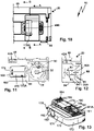
- the suction inlet 12 can be closed by a closure element 60 .
- the closure element 60 has a closure body 61 which can be inserted into the suction inlet 12 .
- the closure body 61 is therefore designed as a plug-in projection or plug-in body.
- the closure element 60 is movably mounted on the suction device housing 20 by means of a bearing 62 between a closed position V and a release position FS, the closure element 60 closing the suction inlet 12 in the closed position V and releasing it in the release position FS.
- the suction inlet 12 In the release position FS, the suction inlet 12 is free or open for arranging, in particular for inserting, the suction hose SL.
- the bearing 62 is a pivot bearing, for example, by means of which the closure element 60 is mounted pivotably about a pivot axis SC.
- the pivot axis SC is, for example, orthogonal to the top surface of the top 45A of the lid 44 or to the top surface of the suction device housing 20.
- the bearing 62 includes a bearing projection 63 on the closure element 60 which engages in a bearing receptacle 64 on the upper side 15 of the cover 44 .
- the bearing mount 64 is designed, for example, as a passage opening on the cover body or the cover wall 46 .
- the bearing projection 63 penetrates the passage opening. From the bearing projection 63, in particular at its free end area, there is a gripping contour 63A, for example a flange-like latching projection or the like, which grips the cover body or the top wall 46 on an underside of the cover 45 facing away from the top 15, so that the closure element 60 is captive, however is pivotally supported on the lid 45 or the suction device housing 20.
- the locking body 61 and the bearing projection 63 are arranged on an arm body 65 of the locking member 60 .
- the arm body 65 extends along a longitudinal axis L60 between the bearing projection 63 and the closure body 61, which are arranged at mutually opposite longitudinal end regions of the arm body 65.
- the arm body 65 is preferably plate-like and/or is designed in the manner of a strap.
- the cover 45 and thus the suction device housing 20 have a closure element receptacle 67 for the closure element 60 .
- the closure element receptacle 67 is designed as a depression on the upper side 45A of the cover 45 .
- a top 66 of the closure element 60 facing away from the top 45A of the cover 45 does not protrude in front of the top 45A of the cover 45 or is behind this top 45A, which is not shown in the exemplary embodiment, but is an option.
- the upper side 45A of the cover 45 is available for stacking another container or suction device housing 20 or also the container attachment 200, which will be explained below, without the closure element 60 representing an interfering contour.
- the closure element receptacle 67 is approximately triangular in plan view, for example, with the bearing 62 being arranged in one corner area of this triangle and the suction inlet 12 and a delivery receptacle 68 being arranged in the other corner areas.
- the supply receptacle 68 is also designed as a plug-in receptacle and has a peripheral wall 69 and a base 70 .
- the suction inlet 12 is designed as a plug-in receptacle with a peripheral wall 71 into which either the form-fit body 61 or the suction hose SL can be inserted.
- the locking body 61 protrudes in front of the arm body 65 in the manner of a locking projection and has a peripheral wall 72 and a bottom 73 .
- a handle portion 74 protrudes from the bottom 70 into an interior space delimited by the peripheral wall 72 and forms a handle 74A for grasping the closure element 60 .
- the closure body 61 preferably the closure element 60 as a whole, consists of a flexible material which, on the one hand, enables a press fit or tight fit in the suction inlet 12 or the delivery receptacle 68, but on the other hand also enables easy handling. This becomes clearer below:
- the arm body 65 is flexible so that the closure body 61 can be moved out of the suction inlet 12 or the delivery receptacle 68 while bending the arm body 65 .
- a correspondingly movable mounting or pivotable mounting on bearing 62 would also be possible in order to pivot closure element 60 not only back and forth about pivot axis SC between supply receptacle 68 and suction inlet 12, but also disengage or disengage transversely to pivot axis SC to pivot into engagement with the staging receptacle 68 and the suction inlet 12 .
- the closure element 60 can be movably mounted in the bearing receptacle 65 about a pivot axis SQ running transversely to the pivot axis SC, so that the closure element 60 can be moved away from the upper side 45A and disengaged from the suction inlet 12 or the delivery receptacle 68 .
- the bearing projection 63 can have a significantly smaller diameter than the bearing mount 64 and thus have a play of movement transversely to the pivot axis SC in the bearing mount 64.
- the handle portion 74 includes a base wall 75 from which side walls 76 project.
- the base wall 75 and side walls 76 form an approximately U-shaped or V-shaped configuration in cross section.
- the side walls 76 extend between the base wall 75 and the bottom 73 of the closure body 61.
- the base wall 75 and the bottom 70 are, for example, parallel to one another.
- the side walls 76 face the peripheral wall 72 of the closure body 61 .
- the side walls 76 are advantageously long enough for the handle section 74 to extend as far as the arm body 65 .
- the base wall 75 is approximately flush with the arm body 65 and/or with the top 45A of the lid 45. This makes it easier to grasp the handle 74A.
- a seal 77 On the outer periphery of the peripheral wall 72 of the closure body 61 is a seal 77, for example in the form of ribs or sealing projections 77A, which rests against the peripheral wall 71 or the peripheral wall 72 in a sealing fit or press fit when the closure body 61 is inserted into the delivery receptacle 68 or the Suction inlet 12 engages.
- the closure body 61 is held reliably in the provision receptacle 68 or the suction inlet 12 .
- the seal 77 ensures that the suction inlet 12 is sealed when no suction hose SL is inserted, so that no dust or other dirt from the dust collection container 36 or the dust collection space 21 can get into the environment. Nevertheless, the operator easily manages to actuate the closure element 60 from the supply receptacle 68 into the suction inlet 12 or vice versa.
- Insertion into the supply receptacle 68 or the suction inlet 12 is possible, for example, by pressing DV on the base wall 75 of the handle section 74.
- actuation from the suction inlet 12 or the delivery receptacle 68 is also easy to effect despite the press fit of the seal 77 on the peripheral wall 71 or 72 .
- the handle section 74 can namely be gripped with a clamp-like gripping movement and pulled out of the suction inlet 12 or the delivery receptacle 68 counter to the direction of actuation of the pressure actuation DV.
- the side walls 76 are parallel to one another or, as in the exemplary embodiment, are inclined at a small angle to one another, so that when an operator grips the handle section 74, he can grip the two side walls 76 like a clamp and move them towards one another, for example by means of a compressive load DO.
- sections of the peripheral wall 72 and thus the seal 77 are actuated away from the peripheral wall 71 or 72, so that the clamping fit of the closure body 61 on the delivery receptacle 68 or the suction inlet 12 is canceled or at least less tight.
- the side walls 76 yield under pressure when the operator acts on them and form recessed grips, so that handling is made even easier.
- rib structures or similar other gripping structures on the gripping section can also be used or handle of a closure member may be provided to facilitate handling.
- the suction device 10 advantageously has a container attachment 200 or is compatible with a container attachment 200 .
- the container attachment 200 preferably has the same contour on its outer circumference as the suction device housing 20.
- the container attachment 200 can be stacked on the suction device 10, namely its suction device housing 20, and connected to it using the coupling means 58 already explained.
- the container attachment 200 includes a suction device housing 220 with a bottom wall 225, from which longitudinal side walls 226, 227, 228 and 229 protrude, which altogether delimit a receiving space 223 of the container attachment 200.
- the receiving space 223 is suitable for receiving the suction hose SL.
- a handle 224 receiving space 223 protrudes from the bottom wall 225 .
- the handle 224 is designed like a handle, so that the container attachment 200 attached to the suction device housing 20 serves as a carrying handle for carrying a stack 9 consisting of the suction device 10 and container attachment 200 .
- the container attachment 200 forms a stacking container 200A.
- the suction hose SL can be wound around the handle 224 so that it serves as a winding aid.
- a passage 222 for the suction hose SL is provided on the bottom wall 225 and is aligned with the suction inlet 12 when the container attachment 200 is attached to the suction device 10 . Furthermore, a lateral opening 221 for the suction hose SL is provided on the longitudinal side wall 28 .
- locking elements 251, 259 are provided as coupling means 58, which are structurally identical to and/or compatible with the locking elements 51 and 59.
- the locking element 51 of the suction device 10 can be brought into engagement with the locking element 259 are to form the stack 9 consisting of suction device 10 and stacked container attachment 200.
- Feet corresponding to feet 54 and 55 are not visible in the drawing on the side of the bottom wall 225 facing away from the receiving space 223, which can be brought into engagement with the receptacles 56 and 57 of the suction device housing 20, so that in combination with the interlocking locking elements 51 and 259 of the coupling means 58, a secure hold of the container attachment 200 on the suction device 10 can be effected in the direction of the stacking axis SR or in the stacking direction.
- the coupling means 58 also readily bring about a fixed connection between the container attachment 200 and the suction device housing 20 transversely to the stacking axis SR.
- Further containers for example containers for transporting tools, can be stacked or stacked underneath on the stack 9, which can be coupled to the container attachment 200 or the suction device housing 20 using coupling means that are compatible with the coupling means 58.
- the container attachment 200 can also be arranged under the suction device housing 20 and connected to it by means of the coupling means 58 to form a stack.
- another container attachment 200 not shown in the drawing, or another suction device 10, not shown, can be attached, for example, to the figure 6 upper container attachment 200 stacked and coupled to form a stack with this using coupling means that are compatible with the coupling means 58.
- the suction device 10 it would now be possible for the suction device 10 to be designed as a suction device that can be operated via a power supply network.
- the suction device 10 is not only extremely compact, but can also be used flexibly, in that the suction device 10 has a power supply device 80 to which energy stores 170, for example so-called battery packs, can be connected.
- energy stores 170 of the same type also referred to below as energy stores 170A, 170B, are provided for the power supply.
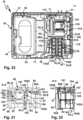
- the power supply device 80 comprises an energy storage receptacle 81 in the region of the suction turbine part 24.
- the energy storage receptacle 81 extends between the longitudinal side wall 28 and the partition wall 30 over almost the entire distance between the longitudinal side wall 28 and the partition wall 30, so that in the energy storage receptacle 81 two energy stores 170 can be arranged.
- the energy store receptacle 81 includes an insertion opening 82 through which the energy store 170 can be inserted into the energy store receptacle 81 .
- the insertion opening 82 is delimited by side walls 83, 84, which run next to the side wall 28 of the suction device housing 20 and the intermediate wall 30 of the suction device housing 20, in particular parallel to the same. Extending between the side walls 83 and 84 is a side wall or connecting wall 85 closer to the cover 45 and a side wall or thick wall 86 closer to the bottom wall 25 or formed by the bottom wall 25.
- the energy storage receptacle 81 is delimited by a bottom wall 87 which is the Insertion opening 82 is opposite.
- Interfaces 90 are arranged on the side walls 83, 84, with which the energy storage devices 170, which have energy storage device interfaces 190 matching the interfaces 90, can be connected.
- the interfaces 90, 190 include complementary longitudinal guide contours 91, 191, which can be inserted into one another along a plug-in axis SA.
- the longitudinal guide contours 91, 191 include longitudinal grooves and longitudinal projections that can engage in one another.
- the interfaces 90, 190 can be connected to one another in a form-fitting manner on the basis of the gripping contours 91A, 191A and the longitudinal guide contours 91, 191, apart from a sliding mobility along the respective plug-in axle SA.
- the interfaces 90, 190 include latching devices 92, 192 in order to latch the energy store 170 to the device interfaces 90.
- the latching devices 92 are designed, for example, as latching receptacles 93 into which the latching projections 193 of the latching devices 192 can engage in a latching manner, so that the energy stores 170 are held in a non-displaceable manner at the interfaces 90 with respect to the plug-in axle SA.
- the latching projections 193 are, for example, spring-loaded or resilient in the direction of their latching position in which they engage in the latching receptacles 93 and can be disengaged from the latching receptacles 93 against the aforementioned spring loading.
- the interfaces 90, 190 include contact arrangements 94, 194 to establish electrical connections between the energy store 170 and the suction device 10.
- the contact arrangements 94, 194 include, for example, energy supply contacts 95, 195 with different polarity, for example a positive potential and ground, as well as data contacts 96, 196 for data transmission between the suction device 10 and the respective energy store 170.
- Such a data transmission sees a digital bus data transmission, for example , especially with an I2C bus.
- Each energy storage device 171 has an energy storage device housing 171, which comprises longitudinal side walls 172 on its longitudinal sides 172A and end-side walls 173, 174 extending between these. Extending between the side walls 172-174 is a bottom wall 175 and, opposite this, an interface wall 176 on which the energy storage interface 190 is arranged.
- the interface wall 176 can have a stepped shape, so that, for example, the data contacts 196 a have a greater distance to the bottom wall 175 than the power supply contacts 195.
- the power supply contacts 195 and the data contacts 196 are arranged one behind the other in relation to the plug-in axle SA.
- the data contacts 196 are arranged at the front along the plug-in axis SA in the plug-in direction, i.e. closer to the end wall 173, while the supply contacts 195 are arranged in the plug-in direction along the plug-in axis SA at the rear, i.e. near the end side wall 174.
- the energy storage housing 171 has an interior 177 in which battery cells 178 are arranged, protected from environmental influences. However, the battery cells 178 heat up, for example, when charging or discharging, ie when the suction device 10 is operated using the energy store 170 .
- each energy store 170 has a fan 179 .
- the fan 179 generates a cooling air flow KL, which flows through an energy store inflow opening 180 into the interior space 177 and through an energy store outflow opening 181 out of the latter.
- the energy storage inflow opening 180 is arranged on the bottom wall 175 while the energy storage outflow opening 181 is arranged on the interface wall 176 .
- the energy storage inflow openings 180 and the energy storage outflow openings 181 are arranged on opposite longitudinal end regions of the energy storage 170, namely close to the end wall 174 and the end wall 173, so that the cooling air flow KL, e.g Cooling air flow KLB, a respective energy storage device 170 flows through, so to speak, from the back to the front with respect to the plug-in direction or plug-in axle SA.
- the cooling air flow KL e.g Cooling air flow KLB
- the device interfaces 90 are arranged on opposite sides of the energy storage receptacle 81, namely on the side walls 83 and 84. Accordingly, the energy stores 170 are accommodated in the energy store receptacle 81 with bottom walls 175 lying opposite one another.
- Operating elements 197 are provided on the longitudinal side walls 172 of the energy storage housing 171 to actuate the latching devices 192 . An operator can therefore grip the energy storage housing 171 laterally and/or in the manner of a clamp, so to speak, in order to simultaneously act on the two operating elements 197 arranged on the opposite longitudinal side walls 172, in order to disengage the locking projections 193 from the locking receptacles 93, so that the respective energy storage device 170 from the device interface 90 is removable.
- the receptacles 81 allow convenient handling, because between the connecting walls 85, 86 and the energy storage devices 170 inserted into the energy storage receptacle 81, there are operating spaces 88 and 89, into which an operator can actuate the operating elements 197, which, for example, have pressure surfaces or Have touch surfaces, can grasp.
- the control rooms 88 and 89 are, so to speak, uniform or continuous control rooms, because there is no separating component between the energy stores 170 accommodated in the energy store receptacle 81 .
- the energy stores 170 were accommodated in the energy store receptacle 81 with the energy store interfaces 190 facing one another, there would have to be a partition in the energy store receptacle 81 on which the device interfaces 90 are arranged.
- the operator can grasp the energy stores 170, for example on their longitudinal side walls 172, in order to remove them from the energy store receptacle 81.
- this also makes operation easier when inserting the energy storage device 170 into the energy storage device receptacle 81, because in this case too the operator can grasp the longitudinal side walls 172 in order to plug a respective energy storage device 170 into the device interface 90 assigned to it.
- the side walls 83, 84 are advantageously spaced apart from one another in such a way that the energy storage devices 170 connected to the device interfaces 90 are connected between their Bottom walls 175 a distance available, so that the cooling air flow KL can flow into the space between the bottom walls 175.
- Outflow openings 97 and 98 which are close to the device interfaces 90 and thus close to the energy storage outflow openings 181 of the energy storage 170 on the side walls 83 and 84 of the energy storage Recording 81 are arranged.
- the vents 97 and 98 are hereinafter referred to as receptacle vents because of their location in the energy storage receptacle 81 and are located close to the bottom wall 87 such that little or no heat builds up in the energy storage receptacle 81 .
- the outflow opening 98 opens directly into an intermediate space between the intermediate wall 30 and the filter element 13, so that a cooling air duct 99 is formed between the intermediate wall 30 and the filter element 13, which leads from the outflow opening 98 to the throughflow opening 32 on the intermediate wall 30 .
- a cooling air flow KLA of the energy store 170 arranged on the side wall 84 can flow out of the receiving outflow opening 98 and is sucked off by the suction turbine 11 via the cooling air duct 99 .
- the suction turbine 11 can even intensify the flow of cooling air KLA, which is indicated schematically by arrows.
- the energy store 170B can be cooled by a cooling air flow KLB, which can flow out of the energy store mount 81 through the outflow opening 97 .
- the receiving outflow opening 97 forms a duct inflow opening 97A for a cooling air duct 100.
- cooling air duct 100 does not lead directly to the through-flow opening 32, but instead opens into a further cooling air duct 101, which is used to cool further components of the suction device 10, for example for cooling an energization device 140 and also for a permanent cooling Cooling of the suction turbine 11.
- the suction turbine 11 is e.g.
- Such permanent cooling of the suction turbine 11 is particularly important when it cannot otherwise suck in sufficient air on the inflow side. Such a situation occurs, for example, when the suction inlet 12 is clogged or blocked, when the filter element 13 is no longer passable, when the dust collection space 21 is overcrowded, or the like.
- the suction turbine 11 is a so-called passage turbine.
- the suction turbine 11 has the suction turbine inflow opening 11A on its side facing the flow opening 32 and at least one, preferably several suction turbine outflow openings 11B on its side facing away from the flow opening 32 .
- a seal 11E is provided between the intermediate wall 30 on the one hand and the end face of the suction turbine 11 which faces the intermediate wall 30 and has the suction turbine inflow opening 11A on the other hand, so that it bears tightly against the intermediate wall 30 and the suction flow S can flow through the through-flow opening 32 can flow, but not in the suction turbine receiving space 31 in which the suction turbine 11 is arranged, flows.
- the suction turbine receiving space 31 is delimited by a side wall 31A in the area of the suction turbine outflow openings 11B.
- a suction turbine bearing element 11F is advantageously arranged, which is elastically flexible, so that this suction turbine bearing element 11F and the seal 11E support the suction turbine 11 in the suction device housing 20 in a vibration-damped manner.
- the suction turbine 11 has a fan 11C, shown schematically, and an electric drive motor 11D for driving the fan 11C.
- the drive motor 11D is cooled by the suction flow S during normal operation of the suction device 10, ie when the suction flow S is flowing.
- the suction device 10 has an energizing device 140 for energizing the suction turbine 11, in particular the drive motor 11D.
- the energizing device 140 includes, for example, one or more power electronic semiconductor elements 141, for example thyristors, MosFets or the like.
- the semiconductor elements 141 heat up during operation, namely when the suction turbine 11 is supplied with current.
- the energizing device 140 is arranged on a printed circuit board 104 which is arranged in a sandwich-like manner between the longitudinal side wall 28 and the side wall 83 of the energy storage receptacle 81 of the power supply device 80 .
- the printed circuit board 104 also partially extends into an intermediate space between the side wall 28 of the side wall 31A.
- the energizing device 140 is connected to the device interfaces 90A, 90B, in particular the energy supply contacts 95, by means of lines 143. Lines 144 connect the energizing device 140 to the suction turbine 11.
- the suction device 10 advantageously has a controller 150 .
- the controller 150 includes, for example, a processor 151 and memory 152, in which at least one control program 153 for controlling the suction turbine 11, for example, is provided.
- An operator can control the suction device 10 using operating elements 155 which are arranged on an operating panel 156 .
- the control panel 156 is arranged on the side wall 28 .
- the controller 150 is electrically connected to the operating elements 155 . With the operating elements 155, the suction device 10 can be switched on or off, for example. Furthermore, the power of the suction turbine 11 can be adjusted using the operating elements 155 .
- a display 157 is advantageously provided on the control panel 156, for example to display a status of the suction device 11.
- the controller 150 also generates heat, the dissipation of which is advantageously solved in the suction device 11, as will become clear below.
- the cooling air duct 101 is flow-connected to the receiving outflow opening 97 . Air can thus flow into the cooling air duct 101 via the intake/outflow opening 97, for example the cooling air flow KLB. However, the cooling air flow KLB has already been heated by the cooling of the energy store 170B.
- Ambient air that is to say generally cooler air, can flow into the cooling air duct 101 via a duct inflow opening 102 as a cooling air flow KLC.
- the channel inflow opening 102 is arranged, for example, close to the bottom wall 25 on an area of the longitudinal side wall 28 facing the bottom wall 25 .
- a protective grid 102A is advantageously arranged on the duct inflow opening 102 .
- the cooling air flow KLC flows via the duct inflow opening 102 into a duct section 103A of the cooling air duct 101, which runs between the printed circuit board 142 and the side wall 31A. Consequently, the cooling air flow KLC flows behind the printed circuit board 142 or the cooling air flow KLC flows past the printed circuit board 142 .
- the channel section 103A is selected such that the cooling air flow KLC essentially flows past the energizing device 140, ie in particular past the semiconductor elements 141, which become particularly warm during operation of the suction device 11. However, such heating and, in the worst case, heating is effectively counteracted using the cooling air flow KLC.
- the duct section 103A opens into a hose receptacle 104, in which a hose 110, thus a tubular body 110A for guiding cooling air, is accommodated.
- the hose receptacle 104 has, for example, a plug-in receptacle 105 into which the hose 110 is inserted, and an air-guiding surface 106 on a wall 107 .
- the cooling air flow KLC flowing out of the duct section 103A is guided into an inlet opening 111 of the hose 110 via the air guiding surface 106 .
- a plug-in stop 105A is advantageously located opposite the plug-in receptacle 105, against which a jacket of the cooling-air hose 110 can strike when it is inserted into the plug-in receptacle 105.
- the plug-in stop 105A is at a distance from the air-guiding surface 106 .
- the inlet opening 111 cannot be closed by the air-guiding surface 106 because of the plug-in stop 105A.
- the cooling air flow KLB can flow past the circuit board 142 and/or in a gap between the circuit board 142 and the cover wall 34 and also into the inlet opening 111 of the cooling air hose 110, so that the cooling air hose 110 flows both the cooling air flow KLB and the cooling air flow KLC in the direction of the channel outflow opening 108 leads.
- the cooling air hose 110 thus provides a common channel section 103B for the cooling air flows KLB and KLC.
- the cooling air hose 110 has a hose section 112 which carries the cooling air flow KLC and/or the cooling air flow KLB to the suction turbine receiving space 31 leads past to a channel outflow opening 108 which is arranged on the intermediate wall 30 and opens into the intermediate space between the intermediate wall 30 and the filter element 13 . There, the cooling air flow KLC and/or the cooling air flow KLB can flow in the direction of the flow opening 32 in order to be sucked off by the suction turbine 11 .
- the hose section 112 has an arcuate course. An end area 113 of the tube section 112 is held in the area of the duct outflow opening 108 in a receptacle 109 which is designed, for example, as a plug-in receptacle.
- cooling air flow KLC cools the power supply device 140, it also cools the suction turbine 11.
- the cooling air ducts 99 and 100 advantageously have smaller flow cross sections than the cooling air duct 101.
- the cooling air duct 101 namely cools the power electronics, e.g. the semiconductor elements 141. This measure helps to ensure that sufficient cooling air flows through the cooling air duct 101 and not, so to speak, past it through the cooling air ducts 99 and/or 100.
- the channel inflow openings 97A, 98A and 102 are permanently open.
- the cooling air flows KLA, KLB and KLC can thus contribute to the cooling of the suction turbine 11 in the long term.
- a sensor 154 is arranged on the suction turbine 11, the sensor signals from which are evaluated by the controller 150.
- the sensor 154 includes or is, for example, a temperature sensor and/or pressure sensor and/or flow sensor. Due to the permanent cooling of the suction turbine 11 using the cooling air flows KLA, KLB and KLC even when the suction flow S is interrupted is flowing or not, there is sufficient flow pressure at the sensor 154 so that it can report valid temperature signals to the controller 150 .
- controller 150 is designed to monitor a volume flow of suction flow S, for example using the at least one control program 153.
- the suction flow S has a volume flow VS, which has a pressure-dependent profile dependent on a pressure P.
- a characteristic VK of a volume flow of the suction flow S is in figure 28 drawn in schematically.
- the volume flow VS has values VS1, VS2 and VS3 in liters per second.
- the suction stream S should not fall below a minimum speed of 20 m/s, for example, so that a so-called dust class is maintained, according to which the suction device 10 always ensures adequate suction for this dust class.
- the required minimum speed of the suction flow S results in a minimum value VSmin for the volume flow of the suction flow S, which is approximately 10 l/s for a hose diameter of 27 mm for the suction hose SL.
- the controller 150 can calculate a characteristic VK of the volume flow of the Determine the intake flow S, because both the characteristic curve VK and the engine characteristics MK1 and MK2 in the area relevant for monitoring the volume flow or the flow rate of the intake flow S have a substantially constant, in particular substantially linear, course.
- the motor characteristics MK1 and MK2 depend on the voltages U1 and U2 with which the drive motor 11D is operated.
- the motor characteristics MK1 and MK2 are proportional to a current curve of the motor current Imot, with which the drive motor 11D is energized by the energizing device 140 .
- the controller 150 controls the energizing device 140 and receives feedback from it, for example, the motor voltage present, for example the motor voltages U1 and U2, and the respective motor current Imot for energizing the drive motor 11D.
- the controller 150 recognizes that the flow rate of the suction flow S is too low and issues a warning on the display 157, for example. In this case, as an alternative or in addition, the controller 150 can also output an acoustic warning to a loudspeaker or another acoustic output means 158 .
- a carrying strap 350 is advantageously suitable for comfortably transporting the suction device 10 or the stack 9 consisting of the suction device 10 and container attachment 200 or the container attachment 200 alone.
- the carrying strap 350 can be fastened either to the suction device 10 or to the container attachment 200.
- the carrying strap 350 has a fastening device 340 on each of its longitudinal end regions.
- the attachment devices 340 can be brought into engagement with attachment receptacles 300 of the suction device 10 or with attachment receptacles 320 of the container attachment 200 as required.
- the fastening devices 340 have base bodies 341 which are designed like plates.
- the base bodies 341 have rear gripping contours 342 on their long sides, which, in cooperation with rear gripping contours 302 of the fastening receptacle 300, serve as longitudinal guides along which the fastening devices 340 can be inserted into a respective fastening receptacle 300 along a plug-in axis S300.
- the base body 341 In the plug-in direction at the front with respect to a plug-in axle S300, the base body 341 has another rear gripping contour 343, the front section 343A of which strikes a stop 303 of the fastening receptacle 300 at the end of the plug-in movement along the plug-in axle S300.
- a bolt 304 of the fastening receptacle 300 which can be actuated using an actuating surface or actuating contour 305, can then reach its locking position, in which it reaches behind and/or over a gripping contour 344 of the fastening device 340.
- the bolt 304 is spring-loaded into its locking position, for example, and can be actuated against this spring loading by means of an actuating surface 305 with an unlocking actuation BE in the direction of its release position.
- the bolt 304 then disengages from the rear gripping contour 344 so that the fastening device 300 can be moved out of the fastening receptacle 300 designed as a plug-in receptacle.
- the rear gripping contour 343 and the rear gripping contour 344 extend between the rear gripping contours 342.
- the rear gripping contour 343 and the rear gripping contour 344 are arranged on opposite longitudinal end regions of the base body 341.
- the attachment mounts 320 are also designed as plug-in mounts.
- a fastening device can be placed in a respective fastening receptacle 320 340 are inserted along a stub axle S320 or are moved out of the mounting receptacle 320 along the stub axle S320.
- the rear gripping contours 343 and 344 of the fastening device 340 act as longitudinal guide contours which can engage with longitudinal guide contours or rear gripping contours 322 of the fastening receptacle 320 and guide the fastening device 340 along the quick-release axle S320.
- One of the rear gripping contours 342 of the fastening device 340 which is at the front in the insertion direction with respect to the stub axle S320, strikes a stop 323 on the bottom or end of the fastening receptacle 320 with respect to the stub axle S320.
- a gripping contour for receiving this gripping contour 342 can optionally be provided there.
- a bolt 346 of the fastening device 340 can then also engage with a locking contour 324 of a locking element 325 of the fastening receptacle 320, so that the fastening device 340 is locked in the fastening receptacle 320.
- the bolt 346 is designed as a resilient tongue or resilient element with respect to the base body 341 and has an actuating surface 345 with which it can be disengaged from the locking contour 324 of the fastening receptacle 320, which is indicated by an arrow or an actuation BE2 in the drawing is.
- the fastening devices 340 have strap mounts 347 for the carrying strap 350 .
- the carrying strap 350 can, for example, be pushed through a push-through opening 348 of a strap holder 347 and be held on the strap holder 347 in a frictionally engaged manner by means of appropriate sling measures.
- the attachment receptacles 320 of the container attachment 200 are located on the longitudinal side walls 228 and 229 in such a way that the carrying strap 340 can be brought into engagement with the attachment receptacles 320 bridging the receiving space 223 of the container attachment 200 .
- the stack 9 can, so to speak, hang down from the carrying strap 350 and be carried comfortably.
- the mounting receptacles 300 allow the suction device 10 to be carried in the manner of a shoulder bag.
- the fastening mounts 300 are arranged on one of the longitudinal side walls 26, 27, 28 or 29, specifically on the longitudinal side wall 26 in the exemplary embodiment. In any case, it is advantageous if the fastening mounts 300 are arranged on the narrow sides of the suction device housing 20 .
- fastening receptacle 300 is arranged in longitudinal end regions of the longitudinal side wall 26, i.e. close to the longitudinal side walls 28 and 29, so that the carrying strap 350 can serve as a strap or carrying handle suitable for hanging on a shoulder in a central section of the longitudinal side wall 26 .
Landscapes
- Engineering & Computer Science (AREA)
- Mechanical Engineering (AREA)
- Refuse Collection And Transfer (AREA)
- Cleaning In General (AREA)
- Manipulator (AREA)
- Filters For Electric Vacuum Cleaners (AREA)
- Packages (AREA)
Abstract
Description
- Die Erfindung betrifft ein Sauggerät mit einem Sauggerät-Gehäuse, in welchem eine Saugturbine zur Erzeugung eines Saugstroms angeordnet ist, wobei die Saugturbine eine Saugturbine-Einströmöffnung, über die der Saugstrom in die Saugturbine einströmen kann, und mindestens eine Saugturbine-Ausströmöffnung aufweist, über die der Saugstrom aus der Saugturbine ausströmen kann, wobei das Sauggerät-Gehäuse einen Saugeinlass zum Einlassen des Saugstroms und einen Staubsammelraum zum Sammeln von in dem Saugstrom enthaltenen Staub aufweist, wobei zwischen dem Staubsammelraum und einer Saugturbine-Einströmöffnung der Saugturbine ein Filterelement zum Zurückhalten von Staub in dem Staubsammelraum angeordnet ist, wobei das Sauggerät ein Verschlusselement mit einem Verschlusskörper zum Verschließen des Saugeinlasses aufweist, welches in einer Verschlussstellung den Saugeinlass verschließt und in einer Freigabestellung aus dem Saugeinlass entfernt ist.
- Zur Lösung der Aufgabe ist bei einem Sauggerät der eingangs genannten Art vorgesehen, dass es eine Bereitstellungsaufnahme zur Aufnahme des Verschlusskörpers aufweist, wenn der Verschlusskörper die Freigabestellung einnimmt.
- In der Freigabestellung ist der Verschlusskörper aus dem Saugeinlass entfernt, sodass der Saugeinlass zum Einstecken oder Anschließen eines Saugschlauches des Sauggeräts bereitsteht. Der Saugschlauch bildet vorteilhaft einen Bestandteil des Sauggeräts und ist lösbar an dem Saugeinlass anordenbar.
- Die Bereitstellungsaufnahme ist beispielsweise neben dem Saugeinlass angeordnet. Die Bereitstellungsaufnahme stellt sozusagen eine Parkposition oder Ruhestellungsaufnahme für den Verschlusskörper dar. Somit ist das Verschlusselement sozusagen stets an Bord des Sauggeräts und steht zum Verschließen des Staubeinlasses jederzeit zur Verfügung.
- Das Verschlusselement ist vorzugsweise als ein einstückiges Verschlusselement ausgestaltet.
- Vorteilhaft ist es, wenn das Verschlusselement aus Kunststoff oder nachgiebigem oder elastischem Material besteht.
- Vorteilhaft ist vorgesehen, dass das Verschlusselement zur Verstellung zwischen der Bereitstellungsaufnahme und dem Saugeinlass anhand eines Lagers beweglich an dem Sauggerät-Gehäuse gelagert ist.
- Insbesondere vorteilhaft ist es, wenn das Verschlusselement unmittelbar am Sauggerät-Gehäuse gelagert ist, d. h. dass das Sauggerät-Gehäuse beispielsweise eine Lageraufnahme oder ein Lagerteil des Lagers zum Lagern des Verschlusselements bildet oder aufweist. Eine vom Sauggerät-Gehäuse separate Lageraufnahme ist bei dieser Ausgestaltung nicht vorgesehen oder vorhanden.
- Vorteilhaft ist es, wenn das Lager ein Schwenklager zur schwenkbaren Lagerung des Verschlusselements um eine Schwenkachse, insbesondere um eine einzige Schwenkachse, ist oder umfasst. Es ist grundsätzlich aber auch möglich, dass das Lager ein Schiebelager umfasst oder als Schiebelager ausgestaltet ist. Bevorzugt ist jedoch eine Schwenklagerung, d. h. ein Schwenklager.
- Bei dem Verschlusselement ist es vorteilhaft, wenn der Verschlusskörper und ein Lagervorsprung des Lagers oder eine Lageraufnahme des Lagers an einem Armkörper des Verschlusselements angeordnet sind. Der Lagervorsprung oder die Lageraufnahme und der Verschlusskörper sind vorteilhaft mit dem Armkörper einstückig.
- Beispielsweise besteht das Verschlusselement als Ganzes einschließlich des Verschlusskörpers und des Lagervorsprungs oder der Lageraufnahme aus Kunststoff.
- Vorteilhaft ist beispielsweise vorgesehen, dass an dem Sauggerät-Gehäuse eine Lageraufnahme, insbesondere eine Bohrung, angeordnet ist, in die der Lagervorsprung eingreift.
- Ein vorteilhaftes Konzept sieht vor, dass der Armkörper eine plattenförmige oder wandartige Gestalt aufweist.
- Vorzugsweise ist der Armkörper in der Art einer Lasche ausgestaltet.
- Weiterhin vorteilhaft ist es, wenn der Verschlusskörper und das Lager, insbesondere der Lagervorsprung, an einander entgegengesetzten Längsendbereichen des Armkörpers angeordnet sind.
- Eine bevorzugte Ausführungsform sieht vor, der Verschlusskörper und ein Lagervorsprung des Lagers zur selben Seite des Armkörpers in Richtung des Sauggerät-Gehäuses vorstehen. Beispielsweise stehen der Lagervorsprung und der Verschlusskörper von dem vorteilhaft wandartigen und/oder plattenartigen in der Art von Zapfen ab.
- Die Bereitstellungsaufnahme und/oder der Saugeinlass sind vorteilhaft als Steckaufnahmen ausgestaltet.
- Vorzugsweise ist vorgesehen, dass der Armkörper quer zu seiner sich zwischen dem Lager und dem Verschlusskörper erstreckenden Längsachse derart biegeflexibel ist, dass er aus der Bereitstellungsaufnahme heraus oder in die Bereitstellungsaufnahme hinein oder aus dem Saugeinlass heraus und in den Saugeinlass hinein quer zu der Längsachse verformbar ist. Der Armkörper kann also beispielsweise in der Art einer Biegelasche verformbar sein, sodass beispielsweise eine Steckbewegung in die Bereitstellungsaufnahme oder den Saugeinlass hinein oder aus diesen heraus möglich ist. Bevorzugt ist es, wenn der Armkörper eine Flachgestalt oder eine geradlinige oder ebene Gestalt aufweist, wenn der Verschlusskörper in dem Saugeinlass oder der Bereitstellungsaufnahme aufgenommen ist.
- Alternativ oder ergänzend zu dem biegeflexiblen Konzept des Armkörpers sind aber auch Alternativen möglich. Beispielsweise kann vorgesehen sein, dass das Lager, anhand dessen der Verschlusskörper zwischen der Bereitstellungsaufnahme und dem Saugeinlass beweglich ist, eine Schiebebeweglichkeit um eine zur Schwenkachse des Lagers parallele oder koaxiale Schiebeachse aufweist. Weiterhin kann das Lager auch eine mehrachsige Schwenkbarkeit des Verschlusskörpers ermöglichen.
- Der Saugeinlass und/oder die Bereitstellungsaufnahme weisen vorzugsweise eine Umfangswand auf. Der Verschlusskörper, insbesondere eine Umfangswand des Verschlusskörpers, liegt vorteilhaft an der jeweiligen Umfangswand an, wenn er in dem Saugeinlass oder Bereitstellungsaufnahme aufgenommen ist.
- Der Verschlusskörper weist vorteilhaft an seinem Außenumfang mindestens eine Dichtung zur dichtenden Anlage an einer Umfangswand des Saugeinlasses und/oder zur klemmenden Anlage an einer Umfangswand der Bereitstellungsaufnahme auf. Beispielsweise sitzt der Verschlusskörper anhand der mindestens einen Dichtung im Klemmsitz in dem Saugeinlass oder der Bereitstellungsaufnahme. Die mindestens eine Dichtung kann beispielsweise einen oder mehrere ringförmige, nach außen vor die Umfangswand oder eine Umfangswand des Verschlusskörpers vorstehende Ringkonturen umfassen.
- Ohne weiteres kann aber auch eine Dichtung an der Ruhestellungsaufnahme und/oder am Saugeinlass angeordnet sein. In diesem Fall ist es auch möglich, dass der Verschlusskörper eine sozusagen glatte oder ebenmäßige Umfangswand aufweist, die keine Dichtkonturen oder dichtende Vorsprünge umfasst oder aufweist.
- Die Bereitstellungsaufnahme weist vorteilhaft eine Bodenwand auf. Zweckmäßigerweise ist vorgesehen, dass eine Bodenwand des Verschlusskörpers der Bodenwand der Bereitstellungsaufnahme gegenüberliegt, wenn der Verschlusskörper in der Bereitstellungsaufnahme aufgenommen ist.
- Ein vorteilhaftes Konzept sieht vor, dass das Verschlusselement einen Handgriff zum Betätigen des Verschlusskörpers in die Bereitstellungsaufnahme hinein oder aus der Bereitstellungsaufnahme heraus aufweist.
- Der Handgriff ist vorzugsweise an dem Verschlusskörper angeordnet, insbesondere in einem Innenraum des Verschlusskörpers angeordnet. Beispielsweise weist der Verschlusskörper eine zylindrische Gestalt auf. Im Innenraum einer zylindrischen Umfangswand des Verschlusskörpers ist vorzugsweise der Handgriff angeordnet. Vorteilhaft ist dabei, wenn der Handgriff nicht vor den Armkörper vorsteht. Somit bildet der Handgriff kein Hindernis, wenn beispielsweise ein Behälteraufsatz oder anderer Staubsammelbehälter, wie nachfolgend noch deutlich wird, auf eine das Verschlusselement aufweisende Partie des Sauggerät-Gehäuses aufgestapelt wird. Vorteilhaft taucht der Bediener zum Ergreifen sozusagen in den Verschlusskörper ein, wenn er den Handgriff ergreift.
- Der Handgriff kann beispielsweise eine Grundwand aufweisen, die eine Druck-Betätigungsfläche zum Drücken des Verschlusskörpers in den Saugeinlass oder die Bereitstellungsaufnahme hinein aufweist.
- Es ist aber auch möglich, dass der Bediener beispielsweise zum Drücken des Verschlusskörpers in die Bereitstellungsaufnahme hinein oder in den Saugeinlass hinein auf eine sich neben dem Handgriff erstreckende Fläche, beispielsweise Bodenwandfläche, des Verschlusskörpers drücken kann.
- Vorteilhaft ist vorgesehen, dass der Handgriff einander gegenüberliegende Seitenwände aufweist, die in der Art eines Klemm-Griffs oder Zangen-Griffs ergreifbar sind und/oder zur Verringerung oder Aufhebung eines Klemmsitzes des Verschlusskörpers in der Bereitstellungsaufnahme oder dem Saugeinlass durch eine Klemm-Betätigung zueinander hin betätigbar sind. Beispielsweise erstrecken sich die Seitenwände etwa parallel oder in einem geringen Winkel zueinander geneigt von der bereits erwähnten Grundwand des Handgriffs in Richtung einer Bodenwand des Verschlusskörpers. Der Bediener kann die beiden Seitenwände beispielsweise zueinander hin bewegen. Die Seitenwände sind beispielsweise über die Bodenwand mit einer Umfangswand des Verschlusskörpers verbunden, sodass eine Krafteinwirkung der Seitenwände des Handgriffs zueinander hin eine Bewegung der Umfangswand des Verschlusskörpers von einer Umfangswand des Saugeinlasses oder der Bereitstellungsaufnahme weg bewirkt.
- Vorzugsweise ist vorgesehen, dass das Verschlusselement an einer Außenwand des Sauggerät-Gehäuses angeordnet ist. Die Außenwand ist vorzugsweise eine Deckwand oder eine Wand an einem Deckel des Sauggeräts. In diesem Zusammenhang ist es vorteilhaft, wenn das Verschlusselement, insbesondere dessen Armkörper, eine Flachgestalt aufweist, sodass das Verschlusselement flach an der Außenwand des Sauggerät-Gehäuses anliegen kann.
- Eine bevorzugte Maßnahme sieht vor, dass an der Außenwand eine Aufnahme, insbesondere eine Aufnahmevertiefung, zur Aufnahme des Verschlusselements angeordnet ist. Die Verschlusselement-Aufnahme ist beispielsweise als eine Aufnahmemulde oder dergleichen ausgestaltet. Bevorzugt ist es, wenn sich von der Verschlusselement-Aufnahme oder Aufnahmevertiefung weg der Saugeinlass und/oder die Bereitstellungsaufnahme, insbesondere in Richtung eines Innenraums des Sauggerät-Gehäuses, erstrecken.
- Ein vorteilhaftes Konzept sieht vor, dass eine Tiefe der Verschlusselement-Aufnahme des Sauggeräts mindestens so groß wie eine Höhe der in der Verschlusselement-Aufnahme aufgenommenen Partie des Verschlusselements ist, sodass das Verschlusselement, wenn es in der Verschlusselement-Aufnahme aufgenommen ist, nicht vor eine Oberfläche der Außenwand vorsteht.
- Vorzugsweise ist das Sauggerät-Gehäuse als ein zur Bildung eines in Richtung einer Stapelachse erstreckenden Gehäusestapels ausgebildetes Stapelgehäuse ausgestaltet, unter welches mindestens ein Stapelbehälter unterstapelbar und/oder auf welches mindestens ein Stapelbehälter aufstapelbar ist. Der Stapelbehälter ist beispielsweise ein weiteres Sauggerät. Es ist aber auch möglich, dass der Stapelbehälter beispielsweise einen Transportbehälter für eine Werkzeugmaschine, insbesondere für eine abrasiv und/oder schneidend arbeitenden Werkzeugmaschine, zum Beispiel eine Schleifmaschine oder Sägemaschine ist. Der dann beim Betrieb der Schleifmaschine oder Sägemaschine anfallende Staub oder anfallende Partikel können anhand des Sauggeräts aufgesaugt werden.
- Es ist zwar möglich, das Sauggerät-Gehäuse auf einen Stapelbehälter sozusagen lose aufzustapeln oder ein Stapelbehälter auf das Sauggerät-Gehäuse aufzustapeln. Das Stapelgehäuse und der weitere Stapelbehälter können aber anhand von an dem Stapelgehäuse des Staubsaugers und dem Stapelbehälter angeordneter Formschlusskonturen optional formschlüssig ineinander eingreifen, sodass sie quer zu der Stapelachse formschlüssig aneinander halten. Dazu können beispielsweise Füße am einen Stapelbehälter oder Stapelgehäuse und Aufnahmen für die Füße am anderen, die Füße stützenden oder aufnehmenden Stapelbehälter oder Stapelgehäuse angeordnet sein, die formschlüssig ineinander eingreifen.
- Vorteilhaft ist bei dem Sauggerät vorgesehen, dass es Koppelmittel zum Koppeln des Sauggerät-Gehäuses mit einem entlang der Stapelachse aufgestapelten oder untergestapelten Stapelbehälter aufweist, wobei die Koppelmittel des Sauggeräts das Sauggerät-Gehäuse zur Zusammenwirkung mit Koppelmitteln des Stapelbehälters ausgestaltet sind, sodass das Sauggerät-Gehäuse mit dem Stapelbehälter quer zur Stapelachse und parallel zur Stapelachse anhand der Koppelmittel fest verbunden ist. Die Koppelmittel umfassen vorteilhaft am Stapelbehälter und Stapelgehäuse angeordnete Hintergreifkonturen, die quer zur Stapelachse in Eingriff und außer Eingriff ineinander bringbar sind. Ferner können die Koppelmittel beispielsweise eines oder mehrere Verriegelungselemente, insbesondere mindestens einen Schwenkriegel und mindestens einen Verriegelungsvorsprung, mit dem der Schwenkriegel in Eingriff bringbar ist, umfassen.
- Vorteilhaft umfasst das Sauggerät einen Behälteraufsatz, der entlang der Stapelachse als ein Stapelbehälter auf das Sauggerät-Gehäuse aufstapelbar oder unter das Sauggerät-Gehäuse unterstapelbar ist, wobei der Behälteraufsatz und das Sauggerät-Gehäuse die Koppelmittel zum festen Koppeln des Sauggerät-Gehäuses mit dem Behälteraufsatz parallel und quer zur Stapelachse aufweisen, und wobei der Behälteraufsatz einen Aufnahmeraum für mindestens eine Komponente, insbesondere einen Saugschlauch, des Sauggeräts aufweist.
- Der Behälteraufsatz weist vorzugsweise eine Durchtrittsöffnung auf, die mit dem Saugeinlass des Sauggerät-Gehäuses fluchtet, wenn der Behälteraufsatz auf dem Sauggerät-Gehäuse angeordnet ist, wobei die Durchtrittsöffnung zum Durchstecken und/oder Einstecken eines Saugschlauches vorgesehen und ausgestaltet ist.
- Die Verschlusselement-Aufnahme und/oder der Saugeinlass und/oder die Bereitstellungsaufnahme sind vorzugsweise an einer Deckwand des Sauggerät-Gehäuses angeordnet, die bei Bildung des Gehäusestapels einem aufgestapelten Stapelbehälter, insbesondere dem Behälteraufsatz, gegenüber liegt. Die Verschlusselement-Aufnahme und/oder die Bereitstellungsaufnahme sind vorzugsweise durch den aufgestapelten Stapelbehälter oder Behälteraufsatz verdeckt oder verdeckbar.
- Das Sauggerät weist vorteilhaft einen in dem Staubsammelraum angeordneten oder den Staubsammelraum bereitstellenden, aus dem Sauggerät-Gehäuse entnehmbaren, insbesondere in der Art einer Kassette ausgestalteten, Staubsammelbehälter auf. Wenn der Staubsammelbehälter in dem Gehäuse aufgenommen ist, liegt er dem Saugeinlass gegenüber. Somit kann strömt der über den Saugeinlass einströmende Saugstrom in den Staubsammelraum des Staubsammelbehälters.
- Ein zur Stromversorgung vorgesehener Energiespeicher umfasst vorzugsweise ein Energiespeicher-Gehäuse, in dessen Innenraum eine Anordnung von Batteriezellen zur Bereitstellung elektrischer Energie angeordnet ist.
- An dem Gehäuse des Sauggeräts elektrischen Geräts ist mindestens eine Geräte-Schnittstelle zur lösbaren Verbindung mit einer Energiespeicher-Schnittstelle des Energiespeichers vorgesehen, wobei die Schnittstellen Kontaktanordnungen zum Herstellen elektrischer Verbindungen über die Schnittstellen umfassen.
- Das Energiespeicher-Gehäuse weist beispielsweise Längsseitenwände auf, die sich zwischen Stirnseitenwänden erstrecken. Die Längsseitenwände und die Stirnseitenwände sind beispielsweise zwischen einer Bodenwand und einer Schnittstellenwand, die einander gegenüberliegen, angeordnet und begrenzen mit diesen Wänden zusammen einen Innenraum des Energiespeicher-Gehäuses.
- Der Energiespeicher umfasst vorteilhaft einen Ventilator zur Erzeugung eines Kühlluftstroms, welche über eine Energiespeicher-Einströmöffnung in das Energiespeicher-Gehäuse einströmen und über eine Energiespeicher-Ausströmöffnung aus dem Energiespeicher-Gehäuse ausströmen kann.
- Nachfolgend wird ein Ausführungsbeispiel der Erfindung anhand der Zeichnung erläutert. Es zeigen:
- Figur 1
- eine perspektivische Schrägansicht eines Sauggeräts von oben, wobei ein Saugeinlass des Sauggeräts offen ist,
- Figur 2
- einen vorderen Teil des Sauggeräts gemäß
Figur 1 etwa entsprechend einem Detail D1 inFigur 1 , wobei der Saugeinlass durch ein Verschlusselement verschlossen ist, - Figur 3
- perspektivische Rückansicht des Sauggeräts gemäß
Figuren 1, 2 , - Figur 4
- das Sauggerät gemäß vorstehender Figuren mit geöffnetem Sauggerät-Gehäuse und einem entfernten Staubsammelbehälter in perspektivischer Schrägansicht von vorn,
- Figur 5
- die Anordnung gemäß
Figur 4 , wobei der Staubsammelbehälter im Sauggerät-Gehäuse des Sauggeräts aufgenommen ist, - Figur 6
- das Sauggerät gemäß vorstehender Figuren mit einem Behälteraufsatz perspektivisch schräg von vorn,
- Figur 7
- eine perspektivische Teil-Rückansicht des Sauggeräts gemäß
Figur 3 , mit entnommenen Energiespeichern, etwa entsprechend einem Ausschnitt D2 inFigur 3 , - Figur 8
- den in
Figur 7 dargestellten Teil des Sauggeräts, jedoch mit anderer Schrägperspektive, - Figur 9
- den in
Figur 7 und 8 dargestellten Teil des Sauggeräts in Frontalansicht mit Energiespeichern, - Figur 10
- die Ansicht entsprechend
Figur 9 , jedoch mit nur einem Energiespeicher, - Figur 11
- einen Schnitt durch das Sauggerät gemäß
Figur 10 , etwa entlang einer Schnittlinie A-A inFigur 10 , - Figur 12
- einen Schnitt durch das Sauggerät gemäß
Figur 10 , etwa entlang einer Schnittlinie B-B inFigur 10 , - Figur 13
- eine perspektivische Schrägansicht eines Energiespeichers des Sauggeräts,
- Figur 14
- eine frontale Ansicht des Sauggeräts von oben, etwa dem Ausschnitt D1 in
Figur 1 entsprechend, wobei wie inFigur 1 der Saugeinlass offen ist, - Figur 15
- die Ansicht entsprechend
Figur 14 , wobei der Saugeinlass durch das Verschlusselement verschlossen ist, - Figur 16
- einen Schnitt durch die Ansicht der
Figur 14 , etwa entlang einer Schnittlinie C-C inFigur 14 , - Figur 17
- einen Schnitt durch die Ansicht gemäß
Figur 15 , etwa entlang einer Schnittlinie D-D inFigur 15 , - Figur 18
- eine frontale Ansicht von oben auf ein offenes Unterteil des Sauggeräts gemäß vorstehender Figuren,
- Figur 19
- einen Schnitt etwa entlang einer Schnittlinie E-E durch das Unterteil des Sauggeräts gemäß
Figur 18 , - Figur 20
- einen Schnitt durch das Sauggerät, etwa entlang einer Schnittlinie F-F in
Figur 18 , - Figur 21
- einen Schnitt durch das Sauggerät, etwa entlang einer Schnittlinie G-G in
Figur 18 , - Figur 22
- einen Schnitt durch das Sauggerät, etwa entlang einer Schnittlinie H-H in
Figur 18 , - Figur 23
- einen Schnitt durch den Teil des Sauggeräts gemäß
Figuren 18 bis 22 , etwa entlang einer Schnittlinie I-I inFigur 20 , - Figur 24
- das Sauggerät gemäß vorstehender Figuren mit einem Tragegurt,
- Figur 25
- ein Detail D3 aus
Figur 24 , jedoch mit entferntem Tragegurt und einer Befestigungseinrichtung des Traggurts, - Figur 26
- das Sauggerät gemäß vorstehender Figuren mit Behälteraufsatz in perspektivischer Schrägansicht, wobei der schematisch dargestellte Tragegurt am Behälteraufsatz befestigt ist,
- Figur 27
- ein Detail D4 aus
Figur 26 , wobei die Befestigungseinrichtung des Traggurts in einer Lösestellung dargestellt ist, - Figur 28
- eine Kennlinie eines Volumenstroms durch die Saugturbine des Sauggeräts, und
- Figur 29
- Motorkennlinien eines Antriebsmotors der Saugturbine.
- Ein Sauggerät 10 weist ein Sauggerät-Gehäuse 20 auf, in dem eine Saugturbine 11 des Sauggeräts 10 aufgenommen ist. Mit der Saugturbine 11 ist ein Saugstrom S erzeugbar, der durch einen Saugeinlass 12 in das Sauggerät-Gehäuse 20 einströmen kann. An den Saugeinlass 12 ist ein Saugschlauch SL anschließbar.
- Der Saugstrom S durchströmt einen Staubsammelraum 21 des Sauggerät-Gehäuses 20, in welchem in dem Saugstrom S enthaltene Partikel, beispielsweise Staub, gesammelt werden können. Zwischen der Saugturbine 11 und dem Staubsammelraum 13 ist ein Filterelement 13, beispielsweise ein Plattenfilter, angeordnet, so dass in dem Saugstrom S enthaltene Partikel in dem Staubsammelraum 21 zurückgehalten werden. Stromabwärts des Filterelements 13 durchströmt der Saugstrom S die Saugturbine 11 und strömt über einen Luftauslass 22 aus dem Sauggerät-Gehäuse 20 aus.
- Das Sauggerät 10 ist ein mobiles elektrisches Gerät, das bequem an seinen Einsatzort gebracht werden kann. Das Sauggerät-Gehäuse 20 ist z.B. kistenförmig und kompakt.
- Das Sauggerät 10 kann mit seiner Unterseite 14 auf einem Untergrund abgestellt werden. Der Saugeinlass 12 ist an einer zur Unterseite 14 entgegengesetzten Oberseite 15 des Sauggeräts 10 angeordnet. Zwischen der Unterseite 14 und der Oberseite 15 weist das Sauggerät 10 oder dessen Sauggerät-Gehäuse 20 längere Längsseiten 16 und 17 auf, von denen die Längsseite 16 beispielsweise eine Vorderseite und die Längsseite 17 eine Rückseite des Sauggeräts 10 bilden.
- In einem Gehäuseinnenraum 23 des Sauggerät-Gehäuses 20 sind der Staubsammelraum 21 und ein Saugturbinenteil 24 vorgesehen, in welchem die Saugturbine 11 aufgenommen ist.
- Das Sauggerät-Gehäuse 20 umfasst eine Bodenwand 25, von der Umfangswände abstehen, nämlich vordere und hintere Längsseitenwände 26, 27 an den Längsseiten 16 und 17 sowie sich zwischen den Längsseitenwänden 26 und 27 erstreckende Längsseitenwände 28 und 29 an den Längsseiten 18 und 19, die insgesamt den Gehäuseinnenraum 23 umschließen.
- Zwischen dem Saugturbinenteil 24 und dem Staubsammelraum 21 ist eine Zwischenwand 30 angeordnet, die den Gehäuseinnenraum 23 sozusagen in den Saugturbinenteil 24 sowie den Staubsammelraum 21 unterteilt.
- An der Zwischenwand 30 ist eine Durchströmöffnung 32 für der Saugstrom S vorgesehen, durch die der Saugstrom S aus dem Staubsammelraum 21 in Richtung des Saugturbinenteils 24, welches einen Saugturbinenaufnahmeraum 31 aufweist, in welchem die Saugturbine 11 aufgenommen ist, strömen kann. Die Zwischenwand 30 könnte man auch als eine Schottwand bezeichnen, die abgesehen von der Durchströmöffnung 32 sowie weiteren noch zu beschreibenden kleinen Ausströmöffnungen 98, 108 den Saugturbinenteil 24 vom Staubsammelraum 21 trennt.
- Der Saugstrom S strömt über den Luftauslass 22 aus dem Saugturbinenaufnahmeraum 31 aus. Der Saugturbinenteil 24 und insbesondere der Saugturbinenaufnahmeraum 31 sind durch eine Abdeckwand 34 verschlossen, während der Staubsammelraum 21 an seiner zu der Bodenwand 25 entgegengesetzten Seite, in Gebrauchslage z.B. oben, offen ist.
- Der Luftauslass 22 ist beispielsweise an einer der Umfangswände des Sauggerät-Gehäuses 20 angeordnet, beispielsweise der vorderen Längsseitenwand 26, wobei aber auch die Längsseitenwände 27 oder 28 einen Luftauslass aufweisen könnten. Vorteilhaft ist es jedenfalls, wenn der Luftauslass 22 nicht an der Bodenwand 25 und/oder nicht an der Abdeckwand 34 angeordnet ist, wobei beides prinzipiell möglich ist.
- Der Staubsammelraum 21 weist ein Aufnahmefach 35 für einen Staubsammelbehälter 36 auf. Der Staubsammelbehälter 36 dient zum Sammeln von Schmutz. Es kann auch ein Filtersack in dem Staubsammelbehälter 36 oder dem Staubsammelraum 21 anordenbar sein.
- Der Staubsammelbehälter 36 ist beispielsweise als eine Art Kassette oder Modul ausgestaltet, welches aus dem Sauggerät-Gehäuse 20 entnommen werden kann, um beispielsweise Staub aus dem Staubsammelbehälter 36 zu entleeren.
- Der Staubsammelbehälter 36 weist eine Bodenwand 37, von der Bodenwand abstehende Seitenwände 38 und 39 sowie eine Filter-Aufnahme 40 für das Filterelement 13 auf, die einen Innenraum 43 des Staubsammelbehälters 36 begrenzen. Das Filterelement 13 liegt der Seitenwand 39 gegenüber. Die Seitenwände 38 erstrecken sich zwischen der Filter-Aufnahme 40 und der Seitenwand 39. Die Seitenwände 38, 39 sowie eine obere Wand der Filter-Aufnahme 40 begrenzen eine Aufnahmeöffnung 41, die der Bodenwand 37 gegenüberliegt. Mithin ist also der Staubsammelbehälter 36 zu seiner Oberseite offen.
- An den Seitenwänden 38 ist ein Tragegriff 42 in der Art eines Henkels anhand von Schwenklagern 42A schwenkbar angelenkt, mit dem der Staubsammelbehälter 36 ergriffen werden kann. Wenn der Tragegriff 42 ausgeschwenkt ist, kann er von einem Bediener ergriffen werden. Wenn der Staubsammelbehälter 36 in das Aufnahmefach 35 eingesetzt ist, kann der Tragegriff 42 in Richtung der Filter-Aufnahme 40 geschwenkt werden, sodass der Tragegriff 42 nicht oder unwesentlich vor die Aufnahmeöffnung 41 vorsteht.
- Vorteilhaft ist vorgesehen, dass der in Richtung der Filteraufnahme 40 geschwenkte Tragegriff 42 den Staubsammelbehälter 36 im Aufnahmefach 35 verriegelt. Zugleich wird zweckmäßigerweise dabei das Filterelement 13 in Richtung der Zwischenwand 30 gespannt, sodass eine Strömungsverbindung zwischen dem Innenraum 43 des Staubsammelbehälters 36 und der Durchströmöffnung 32 und somit der Saugturbine 11 über das Filterelement 13 hergestellt ist.
- Das Saugturbinenteil 24 und der Staubsammelraum 21 bilden Bestandteile eines Gehäuseunterteils 44 des Sauggerät-Gehäuses 20. Das Gehäuseunterteil 44 ist durch einen Deckel 45 verschließbar. Im geöffneten Zustand des Sauggerät-Gehäuses 20 oder einer Offenstellung OD des Deckels 45 ist das Aufnahmefach 35 offen, um den Staubsammelbehälter 36 in das Aufnahmefach 35 einzusetzen oder aus diesem zu entnehmen.
- Der Deckel 45 weist einen Deckelkörper, z.B. eine Deckwand 46, auf, die einen Saugturbinenabschnitt 47 sowie einen Verschlussabschnitt 48 umfasst. Der
- Saugturbinenabschnitt 47 ist dem Saugturbinenteil 24 zugeordnet und liegt der Abdeckwand 34 im geschlossenen Zustand des Deckels 45 gegenüber.
- Der Verschlussabschnitt 48 weist eine Dichtung 49 auf, mit der der Innenraum 43 des Staubsammelbehälters 36 verschließbar ist. Die Dichtung 49 liegt im geschlossenen Zustand des Deckels 45 beispielsweise an den Stirnseiten der Seitenwände 38 und 39 sowie einer die Filter-Aufnahme 40 begrenzenden Seitenwand gegenüber und insbesondere an diesen Seitenwänden 38, 39 sowie dem Außenumfang der Filter-Aufnahme 40 an, sodass der Verschlussabschnitt 48 den Staubsammelbehälter 36 dicht verschließt.
- Der Deckel 45 ist anhand einer Verriegelungseinrichtung 50 mit dem Gehäuseunterteil 44 in einer Schließstellung SD des Deckels 45 verriegelbar.
- Die Verriegelungseinrichtung 50 umfasst ein schwenkbar am Deckel 45 gelagertes Verriegelungselement 51, das in einer Verriegelungsstellung in Eingriff mit einem Verriegelungselement 52 am Gehäuseunterteil 44 ist und in eine Lösestellung schwenkbar ist, in der es außer Eingriff mit dem Verriegelungselement 52 ist. Das Verriegelungselement 51 ist also in der Art eines Schwenkriegels ausgestaltet. Das Verriegelungselement 52 ist an der Längsseitenwand 26 des Gehäuseunterteils 44 angeordnet. Das Verriegelungselement 52 ist beispielsweise als ein Verriegelungsvorsprung ausgestaltet. Korrespondierend zu der vorderseitigen Anordnung des Verriegelungselements 52 ist das Verriegelungselement 51 an einer der Vorderseite oder vorderen Längsseite 16 des Sauggeräts 10 zugeordneten Vorderseite des Deckels 45 angeordnet.
- Der Deckel 45 ist anhand von Schwenklagern 53 schwenkbar am Gehäuseunterteil 44 angelenkt und zwischen seiner Offenstellung OD und seiner Schließstellung SD verschwenkbar. Die Schwenklager 53 sind beispielsweise an der Längsseitenwand 27, insbesondere deren oberen Stirnseite oder Schmalseite, angeordnet.
- Ein optional zwischen dem Deckel 45 und dem Gehäuseunterteil 44 vorhandenes Band 53A, welches beispielsweise an der Abdeckwand 34 und einer dieser gegenüberliegenden Wandfläche des Verschlussabschnitts 48 befestigt ist, begrenzt den Schwenkweg des Deckels 45 in Richtung seiner Offenstellung OD.
- An der Unterseite 14 des Sauggerät-Gehäuses 20 sind Füße 54, 55 angeordnet, mit denen das Sauggerät-Gehäuse 20 auf einem Untergrund abstellbar ist, aber auch in Eingriff mit Aufnahmen 56, 57 mit einem weiteren Sauggerät-Gehäuse 20 eines gleichartigen Sauggeräts 10 in Eingriff gebracht werden kann. Die Füße 54 und die Aufnahmen 56 sind nahe bei der hinteren Längsseitenwand 27 angeordnet. Die Aufnahmen 56 und die Füße 54 weisen Hintergreifkonturen 56A, 54A auf, die quer zu einer Stapelrichtung oder Stapelachse SR in Eingriff und außer Eingriff miteinander bringbar sind und dann, wenn sie in Eingriff miteinander sind, entlang der der Stapelachse SR aufeinandergestapelte Sauggerät-Gehäuse 20 zugfest zu verbinden. Die Hintergreifkonturen 56A, 54A bilden Bestandteile von Koppelmitteln 58. Die Koppelmittel 58 zum Verkoppeln von aufeinandergestapelten Behältern oder Sauggerät-Gehäusen 20 umfassen weiterhin ein Verriegelungselement 59, welches in der Art des Verriegelungselements 52 am Gehäuseunterteil 44 angeordnet ist, jedoch nicht nahe bei der freien Stirnseite der Längsseitenwand 26, sondern nahe bei der Bodenwand 25. Weiterhin bildet auch das Verriegelungselement 51 einen Bestandteil der Koppelmittel 58. Wenn das Verriegelungselement 51 eines jeweils unteren Behälters oder Sauggerät-Gehäuses 20 in Eingriff mit dem Verriegelungselement 59 gebracht wird, indem das Verriegelungselement 51 verschwenkt wird, sind die Behälter oder Sauggerät-Gehäuse 20 auch im Bereich der Vorderseite oder vorderen Längsseite 16 miteinander gekoppelt und somit eine zugfeste Verbindung dieser Sauggerät-Gehäuse 20 in Richtung der Stapelachse SR oder in Stapelrichtung hergestellt.
- Der Saugeinlass 12 ist durch ein Verschlusselement 60 verschließbar.
- Das Verschlusselement 60 weist einen Verschlusskörper 61, der in den Saugeinlass 12 einsteckbar ist. Der Verschlusskörper 61 ist also als ein Steckvorsprung oder Steckkörper ausgestaltet.
- Das Verschlusselement 60 ist anhand eines Lagers 62 zwischen einer Verschlussstellung V und einer Freigabestellung FS an dem Sauggerät-Gehäuse 20 beweglich gelagert, wobei das Verschlusselement 60 in der Verschlussstellung V den Saugeinlass 12 verschließt und in der Freigabestellung FS freigibt. In der Freigabestellung FS ist der Saugeinlass 12 zum Anordnen, insbesondere zum Einstecken des Saugschlauchs SL frei oder offen.
- Das Lager 62 ist beispielsweise ein Schwenklager, anhand dessen das Verschlusselement 60 um eine Schwenkachse SC schwenkbar gelagert ist. Die Schwenkachse SC ist beispielsweise orthogonal zur oberseitigen Fläche der Oberseite 45A des Deckels 44 bzw. zur oberseitigen Fläche des Sauggerät-Gehäuses 20.
- Das Lager 62 umfasst einen Lagervorsprung 63 am Verschlusselement 60, der in eine Lageraufnahme 64 an der Oberseite 15 des Deckels 44 eingreift. Die Lageraufnahme 64 ist beispielsweise als eine Durchtrittsöffnung an dem Deckelkörper oder der Deckwand 46 ausgestaltet. Der Lagervorsprung 63 durchdringt die Durchtrittsöffnung. Von dem Lagervorsprung 63, insbesondere an seinem freien Endbereich, ist eine Hintergreifkontur 63A, beispielsweise ein flanschartiger Rastvorsprung oder dergleichen, die den Deckelkörper oder die Deckwand 46 an einer von der Oberseite 15 abgewandten Unterseite des Deckels 45 hintergreift, sodass das Verschlusselement 60 verliersicher, jedoch schwenkbar an dem Deckel 45 oder dem Sauggerät-Gehäuse 20 gehalten ist.
- Der Verschlusskörper 61 und der Lagervorsprung 63 sind an einem Armkörper 65 des Verschlusselements 60 angeordnet. Der Armkörper 65 erstreckt sich entlang einer Längsachse L60 zwischen dem Lagervorsprung 63 und dem Verschlusskörper 61, welche an einander entgegengesetzten Längsendbereichen des Armkörpers 65 angeordnet sind.
- Der Armkörper 65 ist vorzugsweise plattenartig und/oder ist in der Art einer Lasche ausgestaltet.
- Der Deckel 45 und somit das Sauggerät-Gehäuse 20 weisen eine Verschlusselement-Aufnahme 67 für das Verschlusselement 60 auf. Die Verschlusselement-Aufnahme 67 ist als eine Vertiefung an der Oberseite 45A des Deckels 45 ausgestaltet. Eine von der Oberseite 45A des Deckels 45 abgewandte Oberseite 66 des Verschlusselements 60 steht nicht vor die Oberseite 45A des Deckels 45 vor oder steht hinter diese Oberseite 45A zurück, was jedoch beim Ausführungsbeispiel nicht dargestellt ist, jedoch eine Option darstellt. Somit steht die Oberseite 45A des Deckels 45 zum Aufstapeln eines weiteren Behälters oder Sauggerät-Gehäuses 20 oder auch des nachfolgend noch erläuterten Behälteraufsatzes 200 zur Verfügung, ohne dass das Verschlusselement 60 eine Störkontur darstellt.
- Die Verschlusselement-Aufnahme 67 ist in Draufsicht beispielsweise etwa dreieckförmig, wobei in einem Eckbereich dieses Dreiecks das Lager 62 angeordnet und in den anderen Eckbereichen der Saugeinlass 12 sowie eine Bereitstellungsaufnahme 68 angeordnet sind.
- Auch die Bereitstellungsaufnahme 68 ist als eine Steckaufnahme ausgestaltet und weist eine Umfangswand 69 sowie einen Boden 70 auf.
- Der Saugeinlass 12 ist als eine Steckaufnahme mit einer Umfangswand 71 ausgestaltet, in die wahlweise der Formschlusskörper 61 oder der Saugschlauch SL einsteckbar sind.
- Der Verschlusskörper 61 steht in der Art eines Verschlussvorsprungs vor den Armkörper 65 vor und weist eine Umfangswand 72 sowie einen Boden 73 auf. Von dem Boden 70 steht in einen von der Umfangswand 72 begrenzten Innenraum ein Griffabschnitt 74 vor, der einen Handgriff 74A zum Ergreifen des Verschlusselements 60 bildet.
- Der Verschlusskörper 61, vorzugsweise das Verschlusselement 60 als Ganzes, besteht aus einem flexiblen Material, welches zum einen einen Klemmsitz oder Dichtsitz in dem Saugeinlass 12 oder der Bereitstellungsaufnahme 68 ermöglicht, zum andern aber auch eine bequeme Handhabung ermöglicht. Dies wird nachfolgend deutlicher:
- Beispielsweise ist der Armkörper 65 flexibel, sodass der Verschlusskörper 61 unter Biegung des Armkörpers 65 aus dem Saugeinlass 12 oder der Bereitstellungsaufnahme 68 heraus bewegt werden kann.
- Alternativ oder ergänzend wäre aber auch eine entsprechend bewegliche Lagerung oder schwenkbare Lagerung am Lager 62 möglich, um das Verschlusselement 60 nicht nur um Schwenkachse SC zwischen der Bereitstellungsaufnahme 68 und dem Saugeinlass 12 hin und her zu schwenken, sondern auch quer zur Schwenkachse SC außer Eingriff oder in Eingriff mit der Bereitstellungsaufnahme 68 und dem Saugeinlass 12 zu schwenken. Beispielsweise kann das Verschlusselement 60 um eine zu der Schwenkachse SC quer verlaufende Schwenkachse SQ in der Lageraufnahme 65 beweglich gelagert sein, sodass das Verschlusselement 60 von der Oberseite 45A weg außer Eingriff mit dem Saugeinlass 12 oder der Bereitstellungsaufnahme 68 beweglich ist. Dazu kann z.B. der Lagervorsprung 63 einen deutlich kleineren Durchmesser haben als die Lageraufnahme 64 und so ein Bewegungsspiel quer zur Schwenkachse SC in der Lageraufnahme 64 aufweisen.
- Der Griffabschnitt 74 umfasst eine Grundwand 75, von der Seitenwände 76 abstehen. Die Grundwand 75 und die Seitenwände 76 bilden eine im Querschnitt etwa U-förmige oder V-förmige Konfiguration. Die Seitenwände 76 erstrecken sich zwischen der Grundwand 75 und dem Boden 73 des Verschlusskörpers 61. Die Grundwand 75 und der Boden 70 sind beispielsweise parallel zueinander. Die Seitenwände 76 liegen der Umfangswand 72 des Verschlusskörpers 61 gegenüber. Vorteilhaft sind die Seitenwände 76 derart lang, dass der Griffabschnitt 74 sich bis zum Armkörper 65 erstreckt. Beispielsweise fluchtet die Grundwand 75 etwa mit dem Armkörper 65 und/oder mit der Oberseite 45A des Deckels 45. Dadurch wird ein Ergreifen des Handgriffs 74A erleichtert.
- Am Außenumfang der Umfangswand 72 des Verschlusskörpers 61 ist eine Dichtung 77, beispielsweise in Gestalt von Rippen oder Dichtvorsprüngen 77A, die an der Umfangswand 71 oder der Umfangswand 72 im Dichtsitz oder Klemmsitz anliegt, wenn der Verschlusskörper 61 in die Bereitstellungsaufnahme 68 oder den Saugeinlass 12 eingreift. Somit wird jedenfalls der Verschlusskörper 61 in der Bereitstellungsaufnahme 68 oder dem Saugeinlass 12 zuverlässig gehalten. Insbesondere sorgt die Dichtung 77 für eine Abdichtung des Saugeinlasses 12, wenn kein Saugschlauch SL eingesteckt ist, sodass kein Staub oder dergleichen anderer Schmutz aus dem Staubsammelbehälter 36 bzw. dem Staubsammelraum 21 in die Umgebung gelangen kann. Gleichwohl gelingt es dem Bediener einfach, das Verschlusselement 60 aus der Bereitstellungsaufnahme 68 heraus in den Saugeinlass 12 zu betätigen oder umgekehrt.
- Das Einstecken in die Bereitstellungsaufnahme 68 oder den Saugeinlass 12 gelingt beispielsweise durch eine Druck-Betätigung DV auf die Grundwand 75 des Griffabschnitts 74.
- Aber auch die Betätigung aus dem Saugeinlass 12 oder der Bereitstellungsaufnahme 68 heraus ist trotz des Klemmsitzes der Dichtung 77 an der Umfangswand 71 oder 72 leicht zu bewirken. Der Griffabschnitt 74 kann nämlich mit einer klammerartigen Griffbewegung ergriffen und entgegen der Betätigungsrichtung der Druck-Betätigung DV aus dem Saugeinlass 12 oder der Bereitstellungsaufnahme 68 herausgezogen werden.
- Beispielsweise sind die Seitenwände 76 parallel zueinander oder wie beim Ausführungsbeispiel in einem kleinen Winkel schräg zueinander geneigt, sodass ein Bediener beim Ergreifen des Griffabschnitts 74 die beiden Seitenwände 76 klammerartig ergreifen und diese zueinander hin bewegen kann, beispielsweise durch eine Druckbelastung DO. Dadurch werden Abschnitte der Umfangswand 72 und somit der Dichtung 77 von der Umfangswand 71 oder 72 weg betätigt, sodass der Klemmsitz des Verschlusskörpers 61 an der Bereitstellungsaufnahme 68 oder dem Saugeinlass 12 aufgehoben oder zumindest weniger fest ist. Zudem kann es vorteilhaft sein, wenn die Seitenwände 76 bei Druckbelastung, wenn der Bediener auf sie einwirkt, nachgeben und Griffmulden ausbilden, sodass die Handhabung noch weiter erleichtert ist. An dieser Stelle sei erwähnt, dass selbstverständlich auch Rippenstrukturen oder dergleichen andere Greifstrukturen an dem Griffabschnitt oder Handgriff eines Verschlusselements vorgesehen sein können, um die Handhabung zu erleichtern.
- Das Sauggerät 10 weist vorteilhaft einen Behälteraufsatz 200 auf oder ist mit einem Behälteraufsatz 200 kompatibel. Der Behälteraufsatz 200 ist vorzugsweise an seinem Außenumfang konturgleich mit dem Sauggerät-Gehäuse 20. Der Behälteraufsatz 200 kann auf das Sauggerät 10, nämlich dessen Sauggerät-Gehäuse 20, aufgestapelt und mit diesem anhand der bereits erläuterten Koppelmittel 58 verbunden werden.
- Beispielsweise umfasst der Behälteraufsatz 200 ein Sauggerät-Gehäuse 220 mit einer Bodenwand 225, von der Längsseitenwände 226, 227, 228 und 229 abstehen, die insgesamt einen Aufnahmeraum 223 des Behälteraufsatzes 200 begrenzen. Der Aufnahmeraum 223 eignet sich zur Aufnahme des Saugschlauchs SL.
- Von der Bodenwand 225 steht ein Handgriff 224 Aufnahmeraum 223 vor. Der Handgriff 224 ist der Art eines Henkels ausgestaltet, sodass der am Sauggerät-Gehäuse 20 befestigte Behälteraufsatz 200 als ein Tragegriff zum Tragen eines Stapels 9 bestehend aus Sauggerät 10 und Behälteraufsatz 200 dient. Das bildet dabei ein Sauggerät-Gehäuse 20 Stapelgehäuse 20A. Der Behälteraufsatz 200 bildet einen Stapelbehälter 200A.
- Zugleich kann der Saugschlauch SL um den Handgriff 224 herum gewickelt werden, sodass dieser als eine Wickelhilfe dient.
- An der Bodenwand 225 ist ein Durchlass 222 für den Saugschlauch SL vorgesehen, der mit dem Saugeinlass 12 fluchtet, wenn der Behälteraufsatz 200 an dem Sauggerät 10 befestigt ist. Weiterhin ist ein seitlicher Durchlass 221 für den Saugschlauch SL an der Längsseitenwand 28 vorgesehen.
- An der Längsseitenwand 226 sind als Koppelmittel 58 Verriegelungselemente 251, 259 vorgesehen, welche baugleich und/oder kompatibel mit den Verriegelungselementen 51 und 59 sind. Somit kann also beispielsweise das Verriegelungselement 51 des Sauggeräts 10 in Eingriff mit dem Verriegelungselement 259 gebracht werden, um den Stapel 9 bestehend aus Sauggerät 10 und aufgestapelten Behälteraufsatz 200 zu bilden.
- In der Zeichnung nicht sichtbar sind den Füßen 54 und 55 entsprechende Füße an der vom Aufnahmeraum 223 abgewandten Seite der Bodenwand 225, die in Eingriff mit den Aufnahmen 56 und 57 des Sauggerät-Gehäuses 20 gebracht werden können, sodass in Kombination mit den ineinander eingreifenden Verriegelungselementen 51 und 259 der Koppelmittel 58 ein zugfester Halt des Behälteraufsatzes 200 am Sauggerät 10 in Richtung der Stapelachse SR oder in Stapelrichtung bewirkt werden kann.
- Ohne weiteres bewirken die Koppelmittel 58 aber auch eine feste Verbindung zwischen dem Behälteraufsatz 200 und dem Sauggerät-Gehäuse 20 quer zur Stapelachse SR.
- Auf den Stapel 9 können weitere Behälter, beispielsweise Behälter zum Transportieren von Werkzeugen, aufgestapelt oder untergestapelt werden, die anhand zu den Koppelmitteln 58 kompatiblen Koppelmittel mit dem Behälteraufsatz 200 oder dem Sauggerät-Gehäuse 20 koppelbar sind. So kann beispielsweise der Behälteraufsatz 200 auch unter dem Sauggerät-Gehäuse 20 angeordnet sein und mit diesem anhand der Koppelmittel 58 einen Stapel bildend verbunden werden. Weiterhin kann ein weiterer in der Zeichnung nicht dargestellte Behälteraufsatz 200 oder ein weiteres nicht dargestelltes Sauggerät 10 beispielsweise auf den in
Figur 6 oberen Behälteraufsatz 200 aufgestapelt und mit diesem anhand von Koppelmitteln, die mit den Koppelmitteln 58 kompatibel sind, einen Stapel bildend gekoppelt werden. - Nun wäre es prinzipiell möglich, dass Sauggerät 10 als ein über ein Stromversorgungsnetz betreibbares Sauggerät auszugestalten. Das Sauggerät 10 ist jedoch nicht nur äußerst kompakt, sondern auch flexibel einsetzbar, indem das Sauggerät 10 eine Stromversorgungseinrichtung 80 aufweist, an die Energiespeicher 170, beispielsweise sogenannte Akkupacks, anschließbar sind.
- Zur Stromversorgung sind beispielsweise zwei gleichartige Energiespeicher 170, nachfolgend auch als Energiespeicher 170A, 170B bezeichnet, vorhanden.
- Die Stromversorgungseinrichtung 80 umfasst eine Energiespeicher-Aufnahme 81 im Bereich des Saugturbinenteils 24. Die Energiespeicher-Aufnahme 81 erstreckt sich zwischen der Längsseitenwand 28 und der Zwischenwand 30 nahezu über den gesamten Abstand zwischen der Längsseitenwand 28 und der Zwischenwand 30, sodass in der Energiespeicher-Aufnahme 81 zwei Energiespeicher 170 anordenbar sind.
- Die Energiespeicher-Aufnahme 81 umfasst eine Einstecköffnung 82, durch die die Energiespeicher 170 in die Energiespeicher-Aufnahme 81 einsteckbar sind. Die Einstecköffnung 82 ist durch Seitenwände 83, 84 begrenzt, die neben der Seitenwand 28 des Sauggerät-Gehäuses 20 sowie der Zwischenwand 30 des Sauggerät-Gehäuses 20, insbesondere parallel zu denselben, verlaufen. Zwischen den Seitenwänden 83 und 84 erstrecken eine näher bei dem Deckel 45 befindliche Seitenwand oder Verbindungswand 85 sowie eine zur Bodenwand 25 nähere oder von der Bodenwand 25 gebildete Seitenwand oder dicken Wand 86. Die Energiespeicher-Aufnahme 81 ist durch eine Bodenwand 87 begrenzt, die der Einstecköffnung 82 gegenüber liegt.
- An den Seitenwänden 83, 84 sind Geräte-Schnittstellen 90A, 90B, nachfolgend auch einheitlich als Schnittstellen 90 bezeichnet, angeordnet, mit denen die Energiespeicher 170 verbindbar sind, die zu den Schnittstellen 90 passende Energiespeicher-Schnittstellen 190 aufweisen.
- Beispielsweise umfassen die Schnittstellen 90, 190 zueinander komplementär passende Längsführungskonturen 91, 191, die ineinander entlang einer Steckachse SA einsteckbar sind. Beispielsweise umfassen die Längsführungskonturen 91, 191 Längsnuten und Längsvorsprüngen, die ineinander eingreifen können.
- Quer zu der jeweiligen Steckachse SA erstrecken sich Hintergreifkonturen 91A, 191A der Schnittstellen 90, 191, mit denen die Energiespeicher 170 quer zur jeweiligen Steckachse SA in formschlüssigen Eingriff mit den Geräte-Schnittstellen 90 bringbar sind.
- Anhand der Hintergreifkonturen 91A, 191A und der Längsführungskonturen 91, 191 sind die Schnittstellen 90, 190 formschlüssig miteinander verbindbar abgesehen von einer Schiebebeweglichkeit entlang der jeweiligen Steckachse SA.
- Weiterhin umfassen die Schnittstellen 90, 190 Rasteinrichtungen 92, 192, um die Energiespeicher 170 an den Geräte-Schnittstellen 90 zu verrasten. Die Rasteinrichtungen 92 sind beispielsweise als Rastaufnahmen 93 ausgestaltet, in die Rastvorsprünge 193 der Rasteinrichtungen 192 rastend eingreifen können, sodass die Energiespeicher 170 an den Schnittstellen 90 bezüglich der Steckachse SA verschiebefest gehalten sind. Die Rastvorsprünge 193 sind beispielsweise federbelastet oder federnd nachgiebig in Richtung ihrer Raststellung, in der sie in die Rastaufnahmen 93 eingreifen und können entgegen der vorgenannten Federbelastung außer Eingriff mit den Rastaufnahmen 93 gebracht werden.
- Die Schnittstellen 90, 190 umfassen Kontaktanordnungen 94, 194, um elektrische Verbindungen zwischen dem Energiespeicher 170 und dem Sauggerät 10 herzustellen. Die Kontaktanordnungen 94, 194 umfassen beispielsweise Energieversorgungskontakte 95, 195 mit unterschiedlicher Polarität, beispielsweise einem positiven Potenzial und Masse, sowie Datenkontakte 96, 196 für eine Datenübertragung zwischen dem Sauggerät 10 und dem jeweiligen Energiespeicher 170. Eine derartige Datenübertragung sieht beispielsweise eine digitale Bus-Datenübertragung, insbesondere mit einem I2C-Bus vor.
- Die Energiespeicher 170 sind vorteilhaft baugleich. Jeder Energiespeicher 171 Energiespeicher-Gehäuse 171 auf, welches an seinen Längsseiten 172A Längsseitenwände 172 sowie sich zwischen diesen erstreckende Stirnseitenwände 173, 174 umfasst. Zwischen den Seitenwänden 172-174 erstrecken sich eine Bodenwand 175 sowie dieser gegenüberliegend eine Schnittstellenwand 176, an der die Energiespeicher-Schnittstelle 190 angeordnet ist. Die Schnittstellenwand 176 kann eine stufige Gestalt aufweisen, sodass beispielsweise die Datenkontakte 196 einen größeren Abstand zu der Bodenwand 175 als die Energieversorgungskontakte 195 aufweisen.
- Weiterhin sind die Energieversorgungskontakte 195 und die Datenkontakte 196 in Bezug auf die Steckachse SA hintereinander angeordnet. Beispielsweise sind die Datenkontakte 196 bezüglich der Steckrichtung entlang der Steckachse SA vorn, das heißt näher bei der Stirnseitenwand 173 angeordnet, während die Versorgungskontakte 195 in Einsteckrichtung entlang der Steckachse SA hinten, also bei der Stirnseitenwand 174 angeordnet sind. Das Energiespeicher-Gehäuse 171 weist einen Innenraum 177 auf, in dem geschützt vor Umwelteinflüssen Batteriezellen 178 angeordnet sind. Allerdings erwärmen sich die Batteriezellen 178 beispielsweise bei einem Aufladen oder Entladen, also wenn das Sauggerät 10 anhand der Energiespeicher 170 betrieben wird. Jedoch sind die Batteriezellen 178 bei den Energiespeichern 170 aktiv gekühlt, wozu jeder Energiespeicher 170 einen Ventilator 179 aufweist. Der Ventilator 179 erzeugt einen Kühlluftstrom KL, der durch eine Energiespeicher-Einströmöffnung 180 in den Innenraum 177 einströmt und durch eine Energiespeicher-Ausströmöffnung 181 aus diesem ausströmend. Beispielsweise ist die Energiespeicher-Einströmöffnung 180 an der Bodenwand 175 angeordnet, während die Energiespeicher-Ausströmöffnung 181 an der Schnittstellenwand 176 angeordnet ist. Zudem sind die Energiespeicher-Einströmöffnungen 180 und die Energiespeicher-Ausströmöffnungen 181 an einander entgegengesetzten Längsendbereichen des Energiespeichers 170, nämlich nahe bei der Stirnseitenwand 174 und der Stirnseitenwand 173 angeordnet, sodass der Kühlluftstrom KL, z.B. beim Energiespeicher 170 ein Kühlluftstrom KLA und beim Energiespeicher 170B ein Kühlluftstrom KLB, einen jeweiligen Energiespeicher 170 sozusagen von hinten nach vorn in Bezug auf die Steckrichtung oder Steckachse SA durchströmt.
- Die Geräte-Schnittstellen 90 sind an einander entgegengesetzten Seiten der Energiespeicher-Aufnahme 81, nämlich an den Seitenwänden 83 und 84 angeordnet. Dementsprechend sind die Energiespeicher 170 mit einander gegenüberliegenden Bodenwänden 175 in der Energiespeicher-Aufnahme 81 aufgenommen. Zur Betätigung der Rasteinrichtungen 192 sind Bedienelemente 197 an den Längsseitenwänden 172 der Energiespeicher-Gehäuse 171 vorgesehen. Ein Bediener kann also die Energiespeicher-Gehäuse 171 sozusagen seitlich und/oder klammerartig umgreifen, um simultan auf die beiden an den einander entgegengesetzten Längsseitenwänden 172 angeordneten Bedienelemente 197 einzuwirken, um die Rastvorsprünge 193 außer Eingriff mit den Rastaufnahmen 93 zu bringen, sodass der jeweilige Energiespeicher 170 von der Geräte-Schnittstelle 90 entfernbar ist.
- Die Aufnahmen 81 erlauben dabei eine bequeme Handhabung, weil nämlich zwischen den Verbindungswänden 85, 86 und den in die Energiespeicher-Aufnahme 81 eingesteckten Energiespeichern 170 Bedienräume 88 und 89 vorhanden sind, in die hinein ein Bediener zum Betätigen der Bedienelemente 197, die beispielsweise Druckflächen oder Tastflächen aufweisen, fassen kann. Die Bedienräume 88 und 89 sind sozusagen einheitliche oder durchgängige Bedienräume, weil zwischen den in der Energiespeicher-Aufnahme 81 aufgenommenen Energiespeichern 170 keine trennende Komponente vorhanden ist. Wenn nämlich beispielsweise die Energiespeicher 170 mit einander zugewandten Energiespeicher-Schnittstellen 190 in der Energiespeicher-Aufnahme 81 aufgenommen wären, müsste eine Zwischenwand in der Energiespeicher-Aufnahme 81 vorhanden sein, an der die Geräte-Schnittstellen 90 angeordnet sind.
- Zudem kann der Bediener aufgrund der großzügigen Auslegung der Bedienräume 88 und 89 die Energiespeicher 170 beispielsweise an deren Längsseitenwänden 172 ergreifen, um sie aus der Energiespeicher-Aufnahme 81 zu entfernen. Ohne weiteres ist die Bedienung aber auch beim Einstecken der Energiespeicher 170 in die Energiespeicher-Aufnahme 81 dadurch erleichtert, weil auch in diesem Fall der Bediener die Längsseitenwände 172 ergreifen kann, um einen jeweiligen Energiespeicher 170 an die ihm zugeordnete Geräte-Schnittstelle 90 anzustecken.
- Vorteilhaft sind die Seitenwände 83, 84 derart zueinander beabstandet, dass die an die Geräte-Schnittstellen 90 angesteckten Energiespeicher 170 zwischen ihren Bodenwänden 175 ein Abstand vorhanden, sodass der Kühlluftstrom KL in den Zwischenraum zwischen den Bodenwänden 175 einströmen kann.
- Zur Abfuhr der Kühlluftströme KL der an den Geräte-Schnittstellen 90 angeordneten Energiespeicher 170 dienen Ausströmöffnungen 97 und 98, die nahe bei den Geräte-Schnittstellen 90 und somit nahe bei den Energiespeicher-Ausströmöffnungen 181 der Energiespeicher 170 an den Seitenwänden 83 und 84 der Energiespeicher-Aufnahme 81 angeordnet sind. Die Ausströmöffnungen 97 und 98 sind nachfolgend wegen ihrer Anordnung in der Energiespeicher-Aufnahme 81 als Aufnahme-Ausströmöffnungen bezeichnet und befinden sich nahe an der Bodenwand 87, sodass sich in der Energiespeicher-Aufnahme 81 wenig oder keine Wärme aufstaut.
- Die Aufnahme-Ausströmöffnung 98 mündet direkt in einen Zwischenraum zwischen die Zwischenwand 30 und dem Filterelement 13, sodass ein Kühlluftkanal 99 zwischen der Zwischenwand 30 und dem Filterelement 13 gebildet ist, der von der Aufnahme-Ausströmöffnung 98 zu der Durchströmöffnung 32 an der Zwischenwand 30 führt. Somit kann ein Kühlluftstrom KLA des an der Seitenwand 84 angeordneten Energiespeichers 170 aus der Aufnahme-Ausströmöffnung 98 ausströmen und wird von der Saugturbine 11 über den Kühlluftkanal 99 abgesaugt. Dabei kann die Saugturbine 11 den Kühlluftstrom KLA sogar noch verstärken, der schematisch durch Pfeile angedeutet ist.
- Der Energiespeicher 170B ist durch einen Kühlluftstrom KLB kühlbar, der durch die Aufnahme-Ausströmöffnung 97 aus der Energiespeicher-Aufnahme 81 ausströmen kann. Die Aufnahme-Ausströmöffnung 97 bildet eine Kanal-Einströmöffnung 97A für einen Kühlluftkanal 100.
- Ohne weiteres ist es möglich, durch beispielsweise eine Schlauchverbindungsleitung oder dergleichen, die Aufnahme-Ausströmöffnung 97 mit der Durchströmöffnung 32 an der Zwischenwand 30 oder jedenfalls eine Saugturbine-Einströmöffnung 11A der Saugturbine 11 strömungstechnisch zu verbinden, sodass der Kühlluftstrom KLB unmittelbar zur Saugturbine 11 strömt bzw. von dieser angesaugt wird.
- Vorliegend ist jedoch eine andere Konstruktion gewählt, bei der der Kühlluftkanal 100 nicht unmittelbar zu der Durchströmöffnung 32 führt, sondern in einen weiteren Kühlluftkanal 101 einmündet, der zur Kühlung weitere Komponenten des Sauggeräts 10 dient, beispielsweise zur Kühlung einer Bestromungseinrichtung 140 sowie auch zu einer dauerhaften Kühlung der Saugturbine 11.
- Die Saugturbine 11 ist z.B. eine sogenannte Durchlassturbine oder eine Turbine die durch den von ihr geförderten Saugstrom gekühlt oder kühlbar ist.
- Eine derartige dauerhafte Kühlung der Saugturbine 11 ist insbesondere dann wesentlich, wenn diese einströmseitig ansonsten nicht ausreichend Luft ansaugen kann. Eine solche Situation tritt beispielsweise auf, wenn der Saugeinlass 12 verstopft ist oder zugehalten wird, wenn das Filterelement 13 nicht mehr durchgängig ist, wenn der Staubsammelraum 21 überfüllt ist oder dergleichen.
- Die Saugturbine 11 ist eine sogenannte Durchlassturbine. Die Saugturbine 11 weist an ihrer der Durchströmöffnung 32 zugewandten Seite die Saugturbine-Einströmöffnung 11A auf und an ihrer von der Durchströmöffnung 32 abgewandten Seite mindestens eine, vorzugsweise mehrere Saugturbine-Ausströmöffnungen 11B auf.
- Vorteilhaft ist es, wenn eine Dichtung 11E zwischen einerseits der Zwischenwand 30 und andererseits der der Zwischenwand 30 zugewandten und die Saugturbine-Einströmöffnung 11A aufweisenden Stirnseite der Saugturbine 11 vorgesehen ist, sodass diese dicht an der Zwischenwand 30 anliegt und der Saugstrom S durch die Durchströmöffnung 32 strömen kann, jedoch nicht in den Saugturbinenaufnahmeraum 31, in welchem die Saugturbine 11 angeordnet ist, strömt.
- Der Saugturbinenaufnahmeraum 31 ist im Bereich der Saugturbine-Ausströmöffnungen 11B durch eine Seitenwand 31A begrenzt. Zwischen der Seitenwand 31A und der Stirnseite der Saugturbine 11, an der oder neben der die Saugturbine-Ausströmöffnungen 11B angeordnet sind, ist vorteilhaft ein Saugturbinenlagerelement 11F angeordnet, welches elastisch nachgiebig ist, sodass dieses Saugturbinenlagerelement 11F und die Dichtung 11E die Saugturbine 11 in dem Sauggerät-Gehäuse 20 schwingungsgedämpft lagern.
- Die Saugturbine 11 weist ein schematisch dargestelltes Gebläse 11C sowie einen elektrischen Antriebsmotor 11D zum Antrieb des Gebläses 11C auf. Der Antriebsmotor 11D wird im Normalbetrieb des Sauggeräts 10, also wenn der Saugstrom S strömt, durch den Saugstrom S gekühlt.
- Zur Bestromung der Saugturbine 11, insbesondere des Antriebsmotors 11D, weist das Sauggerät 10 eine Bestromungseinrichtung 140 auf. Die Bestromungseinrichtung 140 umfasst beispielsweise eine oder mehrere leistungselektronische Halbleiterelemente 141, zum Beispiel Thyristoren, MosFets oder dergleichen. Die Halbleiterelemente 141 erwärmen sich beim Betrieb, nämlich bei der Bestromung der Saugturbine 11.
- Die Bestromungseinrichtung 140 ist an einer Leiterplatte 104 angeordnet, die sandwichartig zwischen der Längsseitenwand 28 sowie der Seitenwand 83 der Energiespeicher-Aufnahme 81 der Stromversorgungseinrichtung 80 angeordnet ist. Teilweise erstreckt sich die Leiterplatte 104 auch noch in einen Zwischenraum zwischen der Seitenwand 28 der Seitenwand 31A. Die Bestromungseinrichtung 140 ist anhand von Leitungen 143 mit den Geräte-Schnittstellen 90A, 90B, insbesondere den Energieversorgungskontakten 95, verbunden. Leitungen 144 verbinden die Bestromungseinrichtung 140 mit der Saugturbine 11.
- Weiterhin weist das Sauggerät 10 vorteilhaft eine Steuerung 150 auf. Die Steuerung 150 umfasst beispielsweise einen Prozessor 151 sowie Speicher 152, in welchem mindestens ein Steuerungsprogramm 153 zur Ansteuerung beispielsweise der Saugturbine 11 vorgesehen sind.
- Anhand von Bedienelementen 155, die an einer Bedienwand 156 angeordnet sind, kann ein Bediener das Sauggerät 10 steuern. Die Bedienwand 156 ist an der Seitenwand 28 angeordnet.
- Die Steuerung 150 ist mit den Bedienelementen 155 elektrisch verbunden. Mit den Bedienelementen 155 kann das Sauggerät 10 beispielsweise eingeschaltet werden oder ausgeschaltet werden. Weiterhin kann die Leistung der Saugturbine 11 anhand der Bedienelemente 155 einstellbar sein. Vorteilhaft ist eine Anzeige 157 an der Bedienwand 156 vorgesehen, beispielsweise um einen Status des Sauggeräts 11 anzuzeigen.
- Auch die Steuerung 150 erzeugt Wärme, deren Abfuhr beim Sauggerät 11, wie nachfolgend deutlich wird, vorteilhaft gelöst ist.
- Der Kühlluftkanal 101 ist mit der Aufnahme-Ausströmöffnung 97 strömungsverbunden. Somit kann Luft in den Kühlluftkanal 101 über die Aufnahme-Ausströmöffnung 97 einströmen, beispielsweise der Kühlluftstrom KLB. Der Kühlluftstrom KLB ist jedoch bereits durch die Kühlung des Energiespeichers 170B erwärmt.
- Umgebungsluft, also in der Regel kühlere Luft, kann als ein Kühlluftstrom KLC über eine Kanal-Einströmöffnung 102 in den Kühlluftkanal 101 einströmen. Die Kanal-Einströmöffnung 102 ist beispielsweise nahe bei der Bodenwand 25 an einem der Bodenwand 25 zugewandten Bereich der Längsseitenwand 28 angeordnet. Vorteilhaft ist an der Kanal-Einströmöffnung 102 ein Schutzgitter 102A angeordnet.
- Der Kühlluftstrom KLC strömt über die Kanal-Einströmöffnung 102 in einen Kanalabschnitt 103A des Kühlluftkanals 101 ein, der zwischen der Leiterplatte 142 und der Seitenwand 31A verläuft. Mithin wird also die Leiterplatte 142 vom Kühlluftstrom KLC hinterströmt oder der Kühlluftstrom KLC strömt an der Leiterplatte 142 vorbei. Dabei ist der Kanalabschnitt 103A so gewählt, dass der Kühlluftstrom KLC im Wesentlichen an der Bestromungseinrichtung 140 vorbeiströmt, also insbesondere an den Halbleiterelementen 141, die beim Betrieb des Sauggeräts 11 besonders warm werden. Einer solchen Erwärmung und schlimmstenfalls Erhitzung wird jedoch anhand des Kühlluftstroms KLC effektiv entgegengewirkt.
- An seinem von der Kanal-Einströmöffnung 102 entfernten mündet der Kanalabschnitt 103A in einer Schlauchaufnahme 104, in der ein Schlauch 110, mithin also ein Rohrkörper 110A zur Führung von Kühlluft, aufgenommen ist.
- Die Schlauchaufnahme 104 weist beispielsweise eine Steckaufnahme 105, in die der Schlauch 110 eingesteckt ist, sowie eine Luftleitfläche 106 an einer Wand 107 auf.
- Der aus dem Kanalabschnitt 103A ausströmende Kühlluftstrom KLC wird über die Luftleitfläche 106 in eine Einlassöffnung 111 des Schlauches 110 geleitet. Zwischen der Einlassöffnung 111 und der Luftleitfläche 106 oder der Wand 107 ist ein Abstand vorhanden, sodass der Kühlluftstrom KLC ungehindert in die Einlassöffnung 111 einströmen kann.
- Die Ausgestaltung und/oder ein Querschnitt der Steckaufnahme 105 gewährleistet, dass der Schlauch 110 nur in einem solchen Maße komprimiert wird, dass er in der Steckaufnahme 105 sicher klemmt, jedoch nicht komprimiert wird derart, dass sein Strömungsquerschnitt zum Durchleiten des Kühlluftstroms KLC nicht mehr ausreicht. Vorteilhaft liegt der Steckaufnahme 105 ein Steckanschlag 105A gegenüber, an der ein Mantel des Kühlluft-Schlauchs 110 beim Einstecken in die Steckaufnahme 105 anschlagen kann. Der Steckanschlag 105A weist einen Abstand zu der Luftleitfläche 106 auf. Die Einlassöffnung 111 kann wegen des Steckanschlags 105A nicht durch die Luftleitfläche 106 verschlossen werden.
- Der Kühlluftstrom KLB kann an der Leiterplatte 142 vorbei und/oder in einem Zwischenraum zwischen der Leiterplatte 142 und der Abdeckwand 34 auch in die Einlassöffnung 111 des Kühlluft-Schlauchs 110 einströmen, sodass der Kühlluft-Schlauch 110 sowohl den Kühlluftstrom KLB als auch den Kühlluftstrom KLC in Richtung der Kanal-Ausströmöffnung 108 führt. Der Kühlluft-Schlauch 110 stellt somit einen gemeinsamen Kanalabschnitt 103B für die Kühlluftströme KLB und KLC bereit.
- Der Kühlluft-Schlauch 110 weist einen Schlauchabschnitt 112 auf, der den Kühlluftstrom KLC und/oder den Kühlluftstrom KLB an dem Saugturbinenaufnahmeraum 31 vorbei bis zu einer Kanal-Ausströmöffnung 108 führt, die an der Zwischenwand 30 angeordnet ist und in den Zwischenraum zwischen der Zwischenwand 30 und dem Filterelement 13 ausmündet. Dort kann der Kühlluftstrom KLC und/oder der Kühlluftstrom KLB in Richtung der Durchströmöffnung 32 strömen, um von der Saugturbine 11 abgesaugt zu werden.
- Der Schlauchabschnitt 112 weist einen bogenförmigen Verlauf auf. Ein Endbereich 113 des Schlauchabschnitts 112 ist im Bereich der Kanal-Ausströmöffnung 108 in einer Aufnahme 109 gehalten, die beispielsweise als eine Steckaufnahme ausgestaltet ist.
- Die Kühlluftströme KLA, KLB kühlen zwar primär die Energiespeicher 170A, 170B, zudem aber auch die Saugturbine 11.
- Weiterhin kühlt der Kühlluftstrom KLC zwar die Bestromungseinrichtung 140, zudem aber auch die Saugturbine 11.
- Da zur Kühlung der Energiespeicher 170A, 170B kleinere Kühlluftströme notwendig sind, weisen die Kühlluftkanäle 99 und 100 vorteilhaft kleinere Strömungsquerschnitte auf als der Kühlluftkanal 101. Der Kühlluftkanal 101 kühlt nämlich die Leistungselektronik, z.B. die Halbleiterelemente 141. Diese Maßnahme trägt dazu bei, dass ausreichend Kühlluft durch den Kühlluftkanal 101 strömt und nicht sozusagen an diesem vorbei durch die Kühlluftkanäle 99 und/oder 100.
- Die Kanal-Einströmöffnungen 97A, 98A sowie 102 sind dauerhaft geöffnet. Somit können die Kühlluftströme KLA, KLB und KLC dauerhaft zur Kühlung der Saugturbine 11 beitragen.
- Weiterhin ist an der Saugturbine 11 ein Sensor 154 angeordnet, dessen Sensorsignale von der Steuerung 150 ausgewertet werden. Der Sensor 154 umfasst oder ist beispielsweise ein Temperatursensor und/oder Drucksensor und/oder Strömungssensor. Durch die dauerhafte Kühlung der Saugturbine 11 anhand der Kühlluftströme KLA, KLB und KLC auch dann, wenn der Saugstrom S unterbrochen ist oder nicht strömt, ausreichend Strömungsdruck am Sensor 154 vorhanden, sodass dieser valide Temperatursignale an die Steuerung 150 melden kann.
- Schließlich ist die Steuerung 150 zur Überwachung eines Volumenstroms des Saugstroms S ausgestaltet, beispielsweise anhand des mindestens einen Steuerungsprogramms 153.
- Beispielsweise weist der Saugstrom S einen Volumenstrom VS auf, der einen druckabhängigen Verlauf abhängig von einem Druck P aufweist. Ein Kennlinie VK eines Volumenstroms des Saugstroms S ist in
Figur 28 schematisch eingezeichnet. Bei Drücken P1, P2 und P3, die negativ sind oder Unterdrücke sind, weist der Volumenstrom VS beispielsweise Werte VS1, VS2 und VS3 in Litern pro Sekunde auf. - Der Saugstrom S soll beispielsweise nicht unter eine Minimalgeschwindigkeit von beispielsweise 20 m/s fallen, sodass beispielsweise eine sogenannte Staubklasse eingehalten wird, gemäß der das Sauggerät 10 stets eine für diese Staubklasse ausreichende Absaugung gewährleistet.
- Abhängig von einem Durchmesser des Saugschlauches SL ergibt sich aus der geforderten Minimalgeschwindigkeit des Saugstroms S ein Minimalwert VSmin für den Volumenstrom des Saugstroms S, der beispielsweise bei einem Schlauchdurchmesser von 27 mm des Saugschlauchs SL ca. 10 l/s beträgt.
- Durch den konstanten Luftstrom, der unter anderem durch die Kühlluftströme KLA, KLB und KLC bereitgestellt wird, kann die Steuerung 150 anhand von Motorkennlinien MK1 und MK2 sowie weiteren, in der Zeichnung nicht dargestellten Motorkennlinien des Antriebsmotors 11D der Saugturbine 11 eine Kennlinie VK des Volumenstroms des Saugstroms S ermitteln, weil nämlich sowohl die Kennlinie VK als auch die Motorkennlinien MK1 und MK2 in dem für die Überwachung des Volumenstroms bzw. der Strömungsgeschwindigkeit des Saugstroms S relevanten Bereich einen im Wesentlichen konstanten, insbesondere im Wesentlichen linearen, Verlauf aufweisen.
- Die Motorkennlinien MK1 und MK2 sind abhängig von Spannungen U1 und U2, mit denen der Antriebsmotor 11D betrieben wird. Die Motorkennlinien MK1 und MK2 sind proportional zu einem Stromverlauf des Motorstroms Imot, mit dem der Antriebsmotor 11D durch die Bestromungseinrichtung 140 bestromt wird.
- Die Steuerung 150, insbesondere das Steuerungsprogramm 153, steuert die Bestromungseinrichtung 140 an und erhält von dieser als Rückmeldung beispielsweise die jeweils anliegende Motorspannung, beispielsweise die Motorspannungen U1 und U2, sowie den jeweiligen Motorstrom Imot zur Bestromung des Antriebsmotors 11D.
- Wenn die Motorkennlinie MK1 bzw. der Motorstrom Imot den Wert I1min oder die Motorkennlinie MK2 bzw. der Motorstrom Imot den Wert I2min unterschreiten, die jeweils mit dem Minimalwert VSmin für den Volumenstrom des Saugstroms S korrespondieren, erkennt die Steuerung 150, dass die Strömungsgeschwindigkeit des Saugstroms S zu gering ist und gibt beispielsweise eine Warnung an der Anzeige 157 aus. Die Steuerung 150 kann in diesem Fall alternativ oder ergänzend auch eine akustische Warnung an einem Lautsprecher oder einem sonstigen akustischen Ausgabemittel 158 ausgeben.
- Zum komfortablen Transportieren des Sauggeräts 10 oder des Stapels 9 bestehend aus Sauggerät 10 und Behälteraufsatz 200 oder auch des Behälteraufsatzes 200 alleine eignet sich vorteilhaft ein Tragegurt 350. Der Tragegurt 350 kann anhand einer Längenverstelleinrichtung 351 ergonomisch an die jeweilige Tragesituation angepasst werden.
- Der Tragegurt 350 ist wahlweise am Sauggerät 10 oder am Behälteraufsatz 200 befestigbar. Dazu weist der Tragegurt 350 an seinen Längsendbereichen jeweils eine Befestigungseinrichtung 340 auf.
- Die Befestigungseinrichtungen 340 können je nach Bedarf mit Befestigungsaufnahmen 300 des Sauggeräts 10 oder mit Befestigungsaufnahmen 320 des Behälteraufsatzes 200 in Eingriff gebracht werden.
- Die Befestigungseinrichtungen 340 weisen Grundkörper 341 auf, die plattenartig ausgestaltet sind.
- Die Grundkörper 341 weisen an ihren Längsseiten Hintergreifkonturen 342 auf, die in Zusammenwirkung mit Hintergreifkonturen 302 der Befestigungsaufnahme 300 als Längsführungen dienen, entlang derer die Befestigungseinrichtungen 340 in eine jeweilige Befestigungsaufnahme 300 entlang einer Steckachse S300 einsteckbar sind.
- In Steckrichtung vorn bezüglich einer Steckachse S300 weist der Grundkörper 341 eine weitere Hintergreifkontur 343 auf, deren vorderer Abschnitt 343A an einem Anschlag 303 der Befestigungsaufnahme 300 am Ende der Steckbewegung entlang der Steckachse S300 anschlägt.
- Dann kann ein Riegel 304 der Befestigungsaufnahme 300, der anhand einer Betätigungsfläche oder Betätigungskontur 305 betätigbar ist, in seine Verriegelungsstellung gelangen, in der er hinter und/oder über eine Hintergreifkontur 344 der Befestigungseinrichtung 340 gelangt.
- Der Riegel 304 ist in seine Verriegelungsstellung beispielsweise federbelastet und kann entgegen dieser Federbelastung anhand einer Betätigungsfläche 305 mit einer Entriegelungsbetätigung BE in Richtung seiner Freigabestellung betätigt werden. Dann gelangt der Riegel 304 außer Eingriff mit der Hintergreifkontur 344, sodass die Befestigungseinrichtung 300 wieder aus der als Steckaufnahme ausgestalteten Befestigungsaufnahme 300 heraus bewegt werden kann.
- Die Hintergreifkontur 343 und die Hintergreifkontur 344 erstrecken sich zwischen den Hintergreifkonturen 342. Die Hintergreifkontur 343 und die Hintergreifkontur 344 sind an einander entgegengesetzten Längsendbereichen des Grundkörpers 341 angeordnet.
- Die Befestigungsaufnahmen 320 sind ebenfalls als Steckaufnahmen ausgestaltet. In eine jeweilige Befestigungsaufnahme 320 kann eine Befestigungseinrichtung 340 entlang einer Steckachse S320 eingesteckt werden oder aus der Befestigungsaufnahme 320 entlang der Steckachse S320 heraus bewegt werden.
- Bezüglich der Befestigungsaufnahme 320 wirken die Hintergreifkonturen 343 und 344 der Befestigungseinrichtung 340 als Längsführungskonturen, die in Eingriff mit Längsführungskonturen oder Hintergreifkonturen 322 der Befestigungsaufnahme 320 gelangen können und die Befestigungseinrichtung 340 entlang der Steckachse S320 führen.
- Eine der Hintergreifkonturen 342 der Befestigungseinrichtung 340, die in Steckrichtung bezüglich der Steckachse S320 vorn ist, schlägt an einem Anschlag 323 am Boden oder Ende der Befestigungsaufnahme 320 bezüglich der Steckachse S320 an. Dort kann optional eine Hintergreifkontur zur Aufnahme dieser Hintergreifkontur 342 vorgesehen sein. Dann kann auch ein Riegel 346 der Befestigungseinrichtung 340 in Eingriff mit einer Verriegelungskontur 324 eines Verriegelungselements 325 der Befestigungsaufnahme 320 gelangen, sodass die Befestigungseinrichtung 340 in der Befestigungsaufnahme 320 verriegelt ist.
- Der Riegel 346 ist als federnde Zunge oder federndes Element bezüglich des Grundkörpers 341 ausgestaltet und weist eine Betätigungsfläche 345 auf, mit der er außer Eingriff mit der Verriegelungskontur 324 der Befestigungsaufnahme 320 gebracht werden kann, was durch einen Pfeil oder eine Betätigung BE2 in der Zeichnung angedeutet ist.
- Die Befestigungseinrichtungen 340 weisen Gurtaufnahmen 347 für den Tragegurt 350 auf. Der Tragegurt 350 kann beispielsweise durch eine Durchstecköffnung 348 einer Gurtaufnahme 347 durchgesteckt werden und durch entsprechende Schlingenmaßnahmen an der Gurtaufnahme 347 reibschlüssig gehalten sein.
- Die Befestigungsaufnahmen 320 des Behälteraufsatzes 200 befinden sich an den Längsseitenwänden 228 und 229 derart, dass der Tragegurt 340 den Aufnahmeraum 223 des Behälteraufsatzes 200 überbrückend in Eingriff mit den Befestigungsaufnahmen 320 bringbar ist. Somit kann der Stapel 9 sozusagen vom Tragegurt 350 nach unten hängen und bequem getragen werden.
- Die Befestigungsaufnahmen 300 hingegen ermöglichen ein Tragen des Sauggeräts 10 in der Art einer Umhängetasche. Beispielsweise sind die Befestigungsaufnahme 300 an einer der Längsseitenwände 26, 27,28 oder 29, beim Ausführungsbeispiel konkret an der Längsseitenwand 26 angeordnet. Jedenfalls ist es vorteilhaft, wenn die Befestigungsaufnahmen 300 an Schmalseiten des Sauggerät-Gehäuses 20 angeordnet sind.
- Vorteilhaft ist es, wenn die Befestigungsaufnahme 300 an Längsendbereichen der Längsseitenwand 26 angeordnet ist, also nahe bei den Längsseitenwänden 28 und 29, sodass der Tragegurt 350 einen mittleren Abschnitt der Längsseitenwand 26 als ein zum Umhängen an einer Schulter geeigneter Gurt oder Hand-Tragegriff dienen kann.
Claims (15)
- Sauggerät (10) mit einem Sauggerät-Gehäuse (20), in welchem eine Saugturbine (11) zur Erzeugung eines Saugstroms (S) angeordnet ist, wobei die Saugturbine (11) eine Saugturbine-Einströmöffnung (11A), über die der Saugstrom (S) in die Saugturbine (11) einströmen kann, und mindestens eine Saugturbine-Ausströmöffnung (11B) aufweist, über die der Saugstrom (S) aus der Saugturbine (11) ausströmen kann, wobei das Sauggerät-Gehäuse (20) einen Saugeinlass (12) zum Einlassen des Saugstroms (S) und einen Staubsammelraum (21) zum Sammeln von in dem Saugstrom (S) enthaltenen Staub aufweist, wobei zwischen dem Staubsammelraum (21) und einer Saugturbine-Einströmöffnung (11A) der Saugturbine (11) ein Filterelement (13) zum Zurückhalten von Staub in dem Staubsammelraum (21) angeordnet ist, wobei das Sauggerät (10) ein Verschlusselement (60) mit einem Verschlusskörper (61) zum Verschließen des Saugeinlasses (12) aufweist, welches in einer Verschlussstellung (V) den Saugeinlass (12) verschließt und in einer Freigabestellung (FS) aus dem Saugeinlass (12) entfernt ist, dadurch gekennzeichnet, dass es eine Bereitstellungsaufnahme (68) zur Aufnahme des Verschlusskörpers (61) aufweist, wenn der Verschlusskörper (61) die Freigabestellung (FS) einnimmt.
- Sauggerät nach Anspruch 1, dadurch gekennzeichnet, dass das Verschlusselement (60) zur Verstellung zwischen der Bereitstellungsaufnahme (68) und dem Saugeinlass (12) anhand eines Lagers (62) beweglich an dem Sauggerät-Gehäuse (20) gelagert ist.
- Sauggerät nach Anspruch 2, dadurch gekennzeichnet, dass das Lager (62) ein Schwenklager zur schwenkbaren Lagerung des Verschlusselements (60) um eine Schwenkachse (SC), insbesondere um eine einzige Schwenkachse (SC), ist oder umfasst.
- Sauggerät nach Anspruch 2 oder 3, dadurch gekennzeichnet, dass der Verschlusskörper (61) und ein Lagervorsprung (63) oder eine Lageraufnahme des Lagers (62) an einem Armkörper (65) des Verschlusselements (60) angeordnet sind.
- Sauggerät nach Anspruch 4, dadurch gekennzeichnet, dass der Armkörper (65) eine plattenförmige oder wandartige Gestalt aufweist.
- Sauggerät nach Anspruch 4 oder 5, dadurch gekennzeichnet, dass der Verschlusskörper (61) und das Lager (62), insbesondere der Lagervorsprung (63), an einander entgegengesetzten Längsendbereichen des Armkörpers (65) angeordnet sind und/oder dass der Verschlusskörper (61) und ein Lagervorsprung (63) des Lagers (62) zur selben Seite des Armkörpers (65) in Richtung des Sauggerät-Gehäuses (20) vorstehen.
- Sauggerät nach einem der Ansprüche 4 bis 6, dadurch gekennzeichnet, dass der Armkörper (65) quer zu seiner sich zwischen dem Lager (62) und dem Verschlusskörper (61) erstreckenden Längsachse (L60) derart biegeflexibel ist, dass er aus der Bereitstellungsaufnahme (68) heraus oder in die Bereitstellungsaufnahme (68) hinein oder aus dem Saugeinlass (12) heraus und in den Saugeinlass (12) hinein quer zu der Längsachse (L60) verformbar ist.
- Sauggerät nach einem der vorhergehenden Ansprüche, dadurch gekennzeichnet, dass die Bereitstellungsaufnahme (68) und/oder der Saugeinlass (12) als Steckaufnahmen ausgestaltet sind.
- Sauggerät nach einem der vorhergehenden Ansprüche, dadurch gekennzeichnet, dass der Verschlusskörper (61) an seinem Außenumfang mindestens eine Dichtung (77) zur dichtenden Anlage an einer Umfangswand des Saugeinlasses (12) und/oder zur klemmenden Anlage an einer Umfangswand der Bereitstellungsaufnahme (68) aufweist.
- Sauggerät nach einem der vorhergehenden Ansprüche, dadurch gekennzeichnet, dass das Verschlusselement (60) einen Handgriff (74A) zum Betätigen des Verschlusskörpers (61) in die Bereitstellungsaufnahme (68) hinein oder aus der Bereitstellungsaufnahme (68) heraus aufweist.
- Sauggerät nach Anspruch 10, dadurch gekennzeichnet, dass der Handgriff (74A) an dem Verschlusskörper (61), insbesondere einem Innenraum des Verschlusskörpers (61), angeordnet ist und/oder dass der Handgriff (74A) einander gegenüberliegende Seitenwände (76) aufweist, die in der Art eines Klemm-Griffs oder Zangen-Griffs ergreifbar sind und/oder zur Verringerung oder Aufhebung eines Klemmsitzes des Verschlusskörpers (61) in der Bereitstellungsaufnahme (68) oder dem Saugeinlass (12) durch eine Klemm-Betätigung zueinander hin betätigbar sind.
- Sauggerät nach einem der vorhergehenden Ansprüche, dadurch gekennzeichnet, dass es einen in dem Staubsammelraum (21) angeordneten oder den Staubsammelraum (21) bereitstellenden, aus dem Sauggerät-Gehäuse (20) entnehmbaren, insbesondere in der Art einer Kassette ausgestalteten, Staubsammelbehälter (36) aufweist, und/oder dass das Verschlusselement (60) an einer Außenwand, insbesondere einer Deckwand (46), des Sauggerät-Gehäuses (20) angeordnet ist.
- Sauggerät nach einem der vorhergehenden Ansprüche, dadurch gekennzeichnet, dass es an der Außenwand eine Verschlusselement-Aufnahme (67), insbesondere eine Aufnahmevertiefung, zur Aufnahme des Verschlusselements (60) aufweist, wobei vorteilhaft vorgesehen ist, dass eine Tiefe der Verschlusselement-Aufnahme (67) des Sauggeräts (10) mindestens so groß wie eine Höhe der in der Verschlusselement-Aufnahme (67) aufgenommenen Partie des Verschlusselements (60) ist, sodass das Verschlusselement (60), wenn es in der Verschlusselement-Aufnahme (67) aufgenommen ist, nicht vor eine Oberfläche der Außenwand vorsteht.
- Sauggerät nach einem der vorhergehenden Ansprüche, dadurch gekennzeichnet, dass das Sauggerät-Gehäuse (20) als ein zur Bildung eines in Richtung einer Stapelachse (SR) erstreckenden Gehäusestapels (9) ausgebildetes Stapelgehäuse (20A) ausgestaltet ist, unter welches mindestens ein Stapelbehälter (200A) unterstapelbar und/oder auf welches mindestens ein Stapelbehälter (200A) aufstapelbar ist.
- Sauggerät nach Anspruch 14, dadurch gekennzeichnet, dass es Koppelmittel (58) zum Koppeln des Sauggerät-Gehäuses (20) mit einem entlang der Stapelachse (SR) aufgestapelten oder untergestapelten Stapelbehälter (200A) aufweist, wobei die Koppelmittel (58) des Sauggeräts (10) das Sauggerät-Gehäuse (20) zur Zusammenwirkung mit Koppelmitteln (58) des Stapelbehälters (200A) ausgestaltet sind, sodass das Sauggerät-Gehäuse (20) mit dem Stapelbehälter (200A) quer zur Stapelachse (SR) und parallel zur Stapelachse (SR) anhand der Koppelmittel (58) fest verbunden ist, und/oder dass es einen Behälteraufsatz (200) aufweist, der entlang der Stapelachse (SR) als ein Stapelbehälter (200A) auf das Sauggerät-Gehäuse (20) aufstapelbar oder unter das Sauggerät-Gehäuse (20) unterstapelbar ist, wobei der Behälteraufsatz (200) und das Sauggerät-Gehäuse (20) die Koppelmittel (58) zum festen Koppeln des Sauggerät-Gehäuses (20) mit dem Behälteraufsatz (200) parallel und quer zur Stapelachse (SR) aufweisen, und wobei der Behälteraufsatz (200) einen Aufnahmeraum für mindestens eine Komponente, insbesondere einen Saugschlauch (SL), des Sauggeräts (10) aufweist.
Applications Claiming Priority (1)
| Application Number | Priority Date | Filing Date | Title |
|---|---|---|---|
| DE102021121709.1A DE102021121709A1 (de) | 2021-08-20 | 2021-08-20 | Sauggerät mit einem Verschlusselement |
Publications (2)
| Publication Number | Publication Date |
|---|---|
| EP4137024A1 true EP4137024A1 (de) | 2023-02-22 |
| EP4137024B1 EP4137024B1 (de) | 2024-07-17 |
Family
ID=82701725
Family Applications (1)
| Application Number | Title | Priority Date | Filing Date |
|---|---|---|---|
| EP22186385.5A Active EP4137024B1 (de) | 2021-08-20 | 2022-07-22 | Sauggerät mit einem verschlusselement |
Country Status (8)
| Country | Link |
|---|---|
| US (1) | US20230073581A1 (de) |
| EP (1) | EP4137024B1 (de) |
| JP (1) | JP2023029314A (de) |
| CN (1) | CN115919183A (de) |
| AU (1) | AU2022209262A1 (de) |
| DE (1) | DE102021121709A1 (de) |
| DK (1) | DK4137024T3 (de) |
| FI (1) | FI4137024T3 (de) |
Families Citing this family (4)
| Publication number | Priority date | Publication date | Assignee | Title |
|---|---|---|---|---|
| DE102020215390A1 (de) * | 2020-12-04 | 2022-06-09 | Festool Gmbh | Tragbare Energiestation, Stapelanordnung und Verfahren zur Herstellung einer tragbaren Energiestation |
| USD1091990S1 (en) * | 2021-11-05 | 2025-09-02 | Festool Gmbh | Vacuum cleaner |
| US20250286351A1 (en) * | 2024-03-05 | 2025-09-11 | Hong Liu Co., Ltd. | Dust-proof filter structure for power supply panel |
| EP4681588A1 (de) * | 2024-07-19 | 2026-01-21 | Hilti Aktiengesellschaft | Ventilanordnung für eine saugvorrichtung |
Citations (3)
| Publication number | Priority date | Publication date | Assignee | Title |
|---|---|---|---|---|
| DE19753668A1 (de) * | 1997-05-12 | 1998-11-19 | Kwang Ju Electronics Co Ltd | Ferngesteuerter Staubsauger |
| EP1166705A1 (de) * | 2000-06-14 | 2002-01-02 | WAP Reinigungssysteme GmbH & Co. | Verfahren und Vorrichtung zur Filterabreinigung für Staubsauger mittels Druckstoss |
| DE102011015574A1 (de) * | 2011-03-30 | 2012-10-04 | Festool Gmbh | Sauggerät mit einem Motorsensor |
Family Cites Families (8)
| Publication number | Priority date | Publication date | Assignee | Title |
|---|---|---|---|---|
| US2780395A (en) * | 1952-11-14 | 1957-02-05 | Raymond M Schlabach | Container closure construction |
| JPH0355431Y2 (de) * | 1986-01-17 | 1991-12-10 | ||
| JPH089609Y2 (ja) * | 1989-03-01 | 1996-03-21 | 株式会社ソキア | 測量機の壁面開口部の防水キャップ |
| DE4138223C1 (en) * | 1991-11-21 | 1993-02-18 | Alfred Kaercher Gmbh & Co, 7057 Winnenden, De | Vacuum cleaner with cleaning unit for filter - has separate filters closing through holes in parallel between dust collector and suction unit |
| US8833587B2 (en) * | 2011-12-12 | 2014-09-16 | Keepcup Pty Ltd. | Reusable beverage cup |
| DE102012100047B4 (de) | 2012-01-04 | 2021-12-09 | Miele & Cie. Kg | Akkutischsauger mit einem Staubrückhalteventil |
| DE102013012242A1 (de) | 2013-07-23 | 2015-01-29 | Festool Gmbh | Sauggerät mit einem Saugeinlass |
| US10494151B2 (en) * | 2014-04-01 | 2019-12-03 | Gpcp Ip Holdings Llc | Reclosable cup lid |
-
2021
- 2021-08-20 DE DE102021121709.1A patent/DE102021121709A1/de active Pending
-
2022
- 2022-07-22 FI FIEP22186385.5T patent/FI4137024T3/fi active
- 2022-07-22 DK DK22186385.5T patent/DK4137024T3/da active
- 2022-07-22 EP EP22186385.5A patent/EP4137024B1/de active Active
- 2022-07-27 AU AU2022209262A patent/AU2022209262A1/en active Pending
- 2022-08-18 US US17/890,334 patent/US20230073581A1/en active Pending
- 2022-08-19 JP JP2022130921A patent/JP2023029314A/ja active Pending
- 2022-08-19 CN CN202210999379.6A patent/CN115919183A/zh active Pending
Patent Citations (3)
| Publication number | Priority date | Publication date | Assignee | Title |
|---|---|---|---|---|
| DE19753668A1 (de) * | 1997-05-12 | 1998-11-19 | Kwang Ju Electronics Co Ltd | Ferngesteuerter Staubsauger |
| EP1166705A1 (de) * | 2000-06-14 | 2002-01-02 | WAP Reinigungssysteme GmbH & Co. | Verfahren und Vorrichtung zur Filterabreinigung für Staubsauger mittels Druckstoss |
| DE102011015574A1 (de) * | 2011-03-30 | 2012-10-04 | Festool Gmbh | Sauggerät mit einem Motorsensor |
Also Published As
| Publication number | Publication date |
|---|---|
| AU2022209262A1 (en) | 2023-03-09 |
| JP2023029314A (ja) | 2023-03-03 |
| DE102021121709A1 (de) | 2023-02-23 |
| FI4137024T3 (fi) | 2024-09-27 |
| US20230073581A1 (en) | 2023-03-09 |
| EP4137024B1 (de) | 2024-07-17 |
| DK4137024T3 (da) | 2024-08-19 |
| CN115919183A (zh) | 2023-04-07 |
Similar Documents
| Publication | Publication Date | Title |
|---|---|---|
| EP4137024B1 (de) | Sauggerät mit einem verschlusselement | |
| EP4137029B1 (de) | Elektrisches gerät, insbesondere sauggerät oder werkzeugmaschine | |
| EP2637542B1 (de) | Sauggerät | |
| DE102013012215B4 (de) | Sauggerät mit einem Hauptfilter | |
| EP2897513B1 (de) | Staubsauger mit batteriedeckel | |
| DE19831383A1 (de) | Handwerkzeugmaschine mit Staubabsaugung | |
| EP2895045A1 (de) | Staubsauger | |
| DE202015004939U1 (de) | Staubsammler | |
| DE102016105330A1 (de) | Staubsammelvorrichtung mit einer Stützeinrichtung | |
| WO2022122280A1 (de) | Sauggerät mit mindestens einer aufnahme für eine batterie | |
| EP4137023B1 (de) | Sauggerät | |
| EP4258965B1 (de) | Sauggerät mit batterieeinrichtung und filterabreinigungseinrichtung | |
| DE102013012241A1 (de) | Sauggerät mit einem Schmutzsammelbehälter | |
| DE102013012242A1 (de) | Sauggerät mit einem Saugeinlass | |
| DE102016105331A1 (de) | Staubsammelvorrichtung mit einem Deckel für eine Hand-Werkzeugmaschine | |
| EP1429891B1 (de) | Handwerkzeugmaschine mit staubbox | |
| DE102021129515A1 (de) | Elektrisches Gerät, insbesondere Sauggerät oder Werkzeugmaschine | |
| EP0140234B1 (de) | Staubsauger | |
| DE102023135330A1 (de) | Selbstfahrende und selbstlenkende Bodenreinigungsmaschine mit Tragegriff | |
| DE4042371A1 (de) | Akkustaubsauger | |
| EP3332684B1 (de) | Sauggerät mit einem filterelement | |
| DE102023135324A1 (de) | Selbstlenkende und selbstfahrende Bodenreinigungsmaschine mit Gehäuseteilen | |
| DE4030347A1 (de) | Akkustaubsauger | |
| DE9018055U1 (de) | Akkustaubsauger | |
| DE102016105457A1 (de) | Übertragungseinrichtung und damit ausgestatteter Stapelbehälter |
Legal Events
| Date | Code | Title | Description |
|---|---|---|---|
| PUAI | Public reference made under article 153(3) epc to a published international application that has entered the european phase |
Free format text: ORIGINAL CODE: 0009012 |
|
| STAA | Information on the status of an ep patent application or granted ep patent |
Free format text: STATUS: THE APPLICATION HAS BEEN PUBLISHED |
|
| AK | Designated contracting states |
Kind code of ref document: A1 Designated state(s): AL AT BE BG CH CY CZ DE DK EE ES FI FR GB GR HR HU IE IS IT LI LT LU LV MC MK MT NL NO PL PT RO RS SE SI SK SM TR |
|
| STAA | Information on the status of an ep patent application or granted ep patent |
Free format text: STATUS: REQUEST FOR EXAMINATION WAS MADE |
|
| 17P | Request for examination filed |
Effective date: 20230323 |
|
| RBV | Designated contracting states (corrected) |
Designated state(s): AL AT BE BG CH CY CZ DE DK EE ES FI FR GB GR HR HU IE IS IT LI LT LU LV MC MK MT NL NO PL PT RO RS SE SI SK SM TR |
|
| GRAP | Despatch of communication of intention to grant a patent |
Free format text: ORIGINAL CODE: EPIDOSNIGR1 |
|
| STAA | Information on the status of an ep patent application or granted ep patent |
Free format text: STATUS: GRANT OF PATENT IS INTENDED |
|
| INTG | Intention to grant announced |
Effective date: 20240222 |
|
| GRAS | Grant fee paid |
Free format text: ORIGINAL CODE: EPIDOSNIGR3 |
|
| GRAA | (expected) grant |
Free format text: ORIGINAL CODE: 0009210 |
|
| STAA | Information on the status of an ep patent application or granted ep patent |
Free format text: STATUS: THE PATENT HAS BEEN GRANTED |
|
| AK | Designated contracting states |
Kind code of ref document: B1 Designated state(s): AL AT BE BG CH CY CZ DE DK EE ES FI FR GB GR HR HU IE IS IT LI LT LU LV MC MK MT NL NO PL PT RO RS SE SI SK SM TR |
|
| REG | Reference to a national code |
Ref country code: CH Ref legal event code: EP |
|
| REG | Reference to a national code |
Ref country code: DE Ref legal event code: R096 Ref document number: 502022001245 Country of ref document: DE |
|
| P01 | Opt-out of the competence of the unified patent court (upc) registered |
Free format text: CASE NUMBER: APP_40161/2024 Effective date: 20240705 |
|
| REG | Reference to a national code |
Ref country code: IE Ref legal event code: FG4D Free format text: LANGUAGE OF EP DOCUMENT: GERMAN |
|
| REG | Reference to a national code |
Ref country code: DK Ref legal event code: T3 Effective date: 20240812 |
|
| REG | Reference to a national code |
Ref country code: FI Ref legal event code: FGE |
|
| REG | Reference to a national code |
Ref country code: NL Ref legal event code: FP |
|
| REG | Reference to a national code |
Ref country code: LT Ref legal event code: MG9D |
|
| PG25 | Lapsed in a contracting state [announced via postgrant information from national office to epo] |
Ref country code: PT Free format text: LAPSE BECAUSE OF FAILURE TO SUBMIT A TRANSLATION OF THE DESCRIPTION OR TO PAY THE FEE WITHIN THE PRESCRIBED TIME-LIMIT Effective date: 20241118 |
|
| PG25 | Lapsed in a contracting state [announced via postgrant information from national office to epo] |
Ref country code: PT Free format text: LAPSE BECAUSE OF FAILURE TO SUBMIT A TRANSLATION OF THE DESCRIPTION OR TO PAY THE FEE WITHIN THE PRESCRIBED TIME-LIMIT Effective date: 20241118 |
|
| PG25 | Lapsed in a contracting state [announced via postgrant information from national office to epo] |
Ref country code: NO Free format text: LAPSE BECAUSE OF FAILURE TO SUBMIT A TRANSLATION OF THE DESCRIPTION OR TO PAY THE FEE WITHIN THE PRESCRIBED TIME-LIMIT Effective date: 20241017 |
|
| PG25 | Lapsed in a contracting state [announced via postgrant information from national office to epo] |
Ref country code: GR Free format text: LAPSE BECAUSE OF FAILURE TO SUBMIT A TRANSLATION OF THE DESCRIPTION OR TO PAY THE FEE WITHIN THE PRESCRIBED TIME-LIMIT Effective date: 20241018 Ref country code: PL Free format text: LAPSE BECAUSE OF FAILURE TO SUBMIT A TRANSLATION OF THE DESCRIPTION OR TO PAY THE FEE WITHIN THE PRESCRIBED TIME-LIMIT Effective date: 20240717 |
|
| PG25 | Lapsed in a contracting state [announced via postgrant information from national office to epo] |
Ref country code: BG Free format text: LAPSE BECAUSE OF FAILURE TO SUBMIT A TRANSLATION OF THE DESCRIPTION OR TO PAY THE FEE WITHIN THE PRESCRIBED TIME-LIMIT Effective date: 20240717 |
|
| PG25 | Lapsed in a contracting state [announced via postgrant information from national office to epo] |
Ref country code: LV Free format text: LAPSE BECAUSE OF FAILURE TO SUBMIT A TRANSLATION OF THE DESCRIPTION OR TO PAY THE FEE WITHIN THE PRESCRIBED TIME-LIMIT Effective date: 20240717 |
|
| PG25 | Lapsed in a contracting state [announced via postgrant information from national office to epo] |
Ref country code: IS Free format text: LAPSE BECAUSE OF FAILURE TO SUBMIT A TRANSLATION OF THE DESCRIPTION OR TO PAY THE FEE WITHIN THE PRESCRIBED TIME-LIMIT Effective date: 20241117 |
|
| PG25 | Lapsed in a contracting state [announced via postgrant information from national office to epo] |
Ref country code: HR Free format text: LAPSE BECAUSE OF FAILURE TO SUBMIT A TRANSLATION OF THE DESCRIPTION OR TO PAY THE FEE WITHIN THE PRESCRIBED TIME-LIMIT Effective date: 20240717 |
|
| PG25 | Lapsed in a contracting state [announced via postgrant information from national office to epo] |
Ref country code: ES Free format text: LAPSE BECAUSE OF FAILURE TO SUBMIT A TRANSLATION OF THE DESCRIPTION OR TO PAY THE FEE WITHIN THE PRESCRIBED TIME-LIMIT Effective date: 20240717 Ref country code: RS Free format text: LAPSE BECAUSE OF FAILURE TO SUBMIT A TRANSLATION OF THE DESCRIPTION OR TO PAY THE FEE WITHIN THE PRESCRIBED TIME-LIMIT Effective date: 20241017 |
|
| PG25 | Lapsed in a contracting state [announced via postgrant information from national office to epo] |
Ref country code: RS Free format text: LAPSE BECAUSE OF FAILURE TO SUBMIT A TRANSLATION OF THE DESCRIPTION OR TO PAY THE FEE WITHIN THE PRESCRIBED TIME-LIMIT Effective date: 20241017 Ref country code: PL Free format text: LAPSE BECAUSE OF FAILURE TO SUBMIT A TRANSLATION OF THE DESCRIPTION OR TO PAY THE FEE WITHIN THE PRESCRIBED TIME-LIMIT Effective date: 20240717 Ref country code: NO Free format text: LAPSE BECAUSE OF FAILURE TO SUBMIT A TRANSLATION OF THE DESCRIPTION OR TO PAY THE FEE WITHIN THE PRESCRIBED TIME-LIMIT Effective date: 20241017 Ref country code: LV Free format text: LAPSE BECAUSE OF FAILURE TO SUBMIT A TRANSLATION OF THE DESCRIPTION OR TO PAY THE FEE WITHIN THE PRESCRIBED TIME-LIMIT Effective date: 20240717 Ref country code: IS Free format text: LAPSE BECAUSE OF FAILURE TO SUBMIT A TRANSLATION OF THE DESCRIPTION OR TO PAY THE FEE WITHIN THE PRESCRIBED TIME-LIMIT Effective date: 20241117 Ref country code: HR Free format text: LAPSE BECAUSE OF FAILURE TO SUBMIT A TRANSLATION OF THE DESCRIPTION OR TO PAY THE FEE WITHIN THE PRESCRIBED TIME-LIMIT Effective date: 20240717 Ref country code: GR Free format text: LAPSE BECAUSE OF FAILURE TO SUBMIT A TRANSLATION OF THE DESCRIPTION OR TO PAY THE FEE WITHIN THE PRESCRIBED TIME-LIMIT Effective date: 20241018 Ref country code: ES Free format text: LAPSE BECAUSE OF FAILURE TO SUBMIT A TRANSLATION OF THE DESCRIPTION OR TO PAY THE FEE WITHIN THE PRESCRIBED TIME-LIMIT Effective date: 20240717 Ref country code: BG Free format text: LAPSE BECAUSE OF FAILURE TO SUBMIT A TRANSLATION OF THE DESCRIPTION OR TO PAY THE FEE WITHIN THE PRESCRIBED TIME-LIMIT Effective date: 20240717 |
|
| PG25 | Lapsed in a contracting state [announced via postgrant information from national office to epo] |
Ref country code: LU Free format text: LAPSE BECAUSE OF NON-PAYMENT OF DUE FEES Effective date: 20240722 |
|
| PG25 | Lapsed in a contracting state [announced via postgrant information from national office to epo] |
Ref country code: LU Free format text: LAPSE BECAUSE OF NON-PAYMENT OF DUE FEES Effective date: 20240722 |
|
| PG25 | Lapsed in a contracting state [announced via postgrant information from national office to epo] |
Ref country code: SM Free format text: LAPSE BECAUSE OF FAILURE TO SUBMIT A TRANSLATION OF THE DESCRIPTION OR TO PAY THE FEE WITHIN THE PRESCRIBED TIME-LIMIT Effective date: 20240717 Ref country code: RO Free format text: LAPSE BECAUSE OF FAILURE TO SUBMIT A TRANSLATION OF THE DESCRIPTION OR TO PAY THE FEE WITHIN THE PRESCRIBED TIME-LIMIT Effective date: 20240717 |
|
| REG | Reference to a national code |
Ref country code: DE Ref legal event code: R097 Ref document number: 502022001245 Country of ref document: DE |
|
| PG25 | Lapsed in a contracting state [announced via postgrant information from national office to epo] |
Ref country code: BE Free format text: LAPSE BECAUSE OF NON-PAYMENT OF DUE FEES Effective date: 20240731 Ref country code: EE Free format text: LAPSE BECAUSE OF FAILURE TO SUBMIT A TRANSLATION OF THE DESCRIPTION OR TO PAY THE FEE WITHIN THE PRESCRIBED TIME-LIMIT Effective date: 20240717 Ref country code: MC Free format text: LAPSE BECAUSE OF FAILURE TO SUBMIT A TRANSLATION OF THE DESCRIPTION OR TO PAY THE FEE WITHIN THE PRESCRIBED TIME-LIMIT Effective date: 20240717 |
|
| PG25 | Lapsed in a contracting state [announced via postgrant information from national office to epo] |
Ref country code: CZ Free format text: LAPSE BECAUSE OF FAILURE TO SUBMIT A TRANSLATION OF THE DESCRIPTION OR TO PAY THE FEE WITHIN THE PRESCRIBED TIME-LIMIT Effective date: 20240717 |
|
| PG25 | Lapsed in a contracting state [announced via postgrant information from national office to epo] |
Ref country code: SK Free format text: LAPSE BECAUSE OF FAILURE TO SUBMIT A TRANSLATION OF THE DESCRIPTION OR TO PAY THE FEE WITHIN THE PRESCRIBED TIME-LIMIT Effective date: 20240717 |
|
| PLBE | No opposition filed within time limit |
Free format text: ORIGINAL CODE: 0009261 |
|
| STAA | Information on the status of an ep patent application or granted ep patent |
Free format text: STATUS: NO OPPOSITION FILED WITHIN TIME LIMIT |
|
| REG | Reference to a national code |
Ref country code: BE Ref legal event code: MM Effective date: 20240731 |
|
| 26N | No opposition filed |
Effective date: 20250422 |
|
| PGFP | Annual fee paid to national office [announced via postgrant information from national office to epo] |
Ref country code: FR Payment date: 20250618 Year of fee payment: 4 |
|
| PG25 | Lapsed in a contracting state [announced via postgrant information from national office to epo] |
Ref country code: IE Free format text: LAPSE BECAUSE OF NON-PAYMENT OF DUE FEES Effective date: 20240722 |
|
| PGFP | Annual fee paid to national office [announced via postgrant information from national office to epo] |
Ref country code: NL Payment date: 20250721 Year of fee payment: 4 |
|
| PG25 | Lapsed in a contracting state [announced via postgrant information from national office to epo] |
Ref country code: SE Free format text: LAPSE BECAUSE OF FAILURE TO SUBMIT A TRANSLATION OF THE DESCRIPTION OR TO PAY THE FEE WITHIN THE PRESCRIBED TIME-LIMIT Effective date: 20240717 |
|
| PGFP | Annual fee paid to national office [announced via postgrant information from national office to epo] |
Ref country code: FI Payment date: 20250725 Year of fee payment: 4 |
|
| PGFP | Annual fee paid to national office [announced via postgrant information from national office to epo] |
Ref country code: DK Payment date: 20250725 Year of fee payment: 4 Ref country code: DE Payment date: 20250618 Year of fee payment: 4 |
|
| PGFP | Annual fee paid to national office [announced via postgrant information from national office to epo] |
Ref country code: AT Payment date: 20251020 Year of fee payment: 4 |
|
| PGFP | Annual fee paid to national office [announced via postgrant information from national office to epo] |
Ref country code: IT Payment date: 20250731 Year of fee payment: 4 |
|
| PG25 | Lapsed in a contracting state [announced via postgrant information from national office to epo] |
Ref country code: IT Free format text: LAPSE BECAUSE OF NON-PAYMENT OF DUE FEES Effective date: 20240722 |
|
| PG25 | Lapsed in a contracting state [announced via postgrant information from national office to epo] |
Ref country code: CY Free format text: LAPSE BECAUSE OF FAILURE TO SUBMIT A TRANSLATION OF THE DESCRIPTION OR TO PAY THE FEE WITHIN THE PRESCRIBED TIME-LIMIT; INVALID AB INITIO Effective date: 20220722 |
|
| REG | Reference to a national code |
Ref country code: CH Ref legal event code: H13 Free format text: ST27 STATUS EVENT CODE: U-0-0-H10-H13 (AS PROVIDED BY THE NATIONAL OFFICE) Effective date: 20260224 |
|
| PG25 | Lapsed in a contracting state [announced via postgrant information from national office to epo] |
Ref country code: HU Free format text: LAPSE BECAUSE OF FAILURE TO SUBMIT A TRANSLATION OF THE DESCRIPTION OR TO PAY THE FEE WITHIN THE PRESCRIBED TIME-LIMIT; INVALID AB INITIO Effective date: 20220722 |
|
| PG25 | Lapsed in a contracting state [announced via postgrant information from national office to epo] |
Ref country code: IT Free format text: LAPSE BECAUSE OF NON-PAYMENT OF DUE FEES Effective date: 20240722 |
|
| PGRI | Patent reinstated in contracting state [announced from national office to epo] |
Ref country code: IT Effective date: 20240731 |
|
| PG25 | Lapsed in a contracting state [announced via postgrant information from national office to epo] |
Ref country code: CH Free format text: LAPSE BECAUSE OF NON-PAYMENT OF DUE FEES Effective date: 20250731 |