EP4137024A1 - Appareil d'aspiration doté d'un élément de fermeture - Google Patents
Appareil d'aspiration doté d'un élément de fermeture Download PDFInfo
- Publication number
- EP4137024A1 EP4137024A1 EP22186385.5A EP22186385A EP4137024A1 EP 4137024 A1 EP4137024 A1 EP 4137024A1 EP 22186385 A EP22186385 A EP 22186385A EP 4137024 A1 EP4137024 A1 EP 4137024A1
- Authority
- EP
- European Patent Office
- Prior art keywords
- suction
- suction device
- receptacle
- closure
- closure element
- Prior art date
- Legal status (The legal status is an assumption and is not a legal conclusion. Google has not performed a legal analysis and makes no representation as to the accuracy of the status listed.)
- Granted
Links
Images


Classifications
-
- A—HUMAN NECESSITIES
- A47—FURNITURE; DOMESTIC ARTICLES OR APPLIANCES; COFFEE MILLS; SPICE MILLS; SUCTION CLEANERS IN GENERAL
- A47L—DOMESTIC WASHING OR CLEANING; SUCTION CLEANERS IN GENERAL
- A47L9/00—Details or accessories of suction cleaners, e.g. mechanical means for controlling the suction or for effecting pulsating action; Storing devices specially adapted to suction cleaners or parts thereof; Carrying-vehicles specially adapted for suction cleaners
- A47L9/0072—Mechanical means for controlling the suction or for effecting pulsating action
-
- A—HUMAN NECESSITIES
- A47—FURNITURE; DOMESTIC ARTICLES OR APPLIANCES; COFFEE MILLS; SPICE MILLS; SUCTION CLEANERS IN GENERAL
- A47L—DOMESTIC WASHING OR CLEANING; SUCTION CLEANERS IN GENERAL
- A47L5/00—Structural features of suction cleaners
-
- A—HUMAN NECESSITIES
- A47—FURNITURE; DOMESTIC ARTICLES OR APPLIANCES; COFFEE MILLS; SPICE MILLS; SUCTION CLEANERS IN GENERAL
- A47L—DOMESTIC WASHING OR CLEANING; SUCTION CLEANERS IN GENERAL
- A47L5/00—Structural features of suction cleaners
- A47L5/12—Structural features of suction cleaners with power-driven air-pumps or air-compressors, e.g. driven by motor vehicle engine vacuum
- A47L5/22—Structural features of suction cleaners with power-driven air-pumps or air-compressors, e.g. driven by motor vehicle engine vacuum with rotary fans
- A47L5/36—Suction cleaners with hose between nozzle and casing; Suction cleaners for fixing on staircases; Suction cleaners for carrying on the back
- A47L5/362—Suction cleaners with hose between nozzle and casing; Suction cleaners for fixing on staircases; Suction cleaners for carrying on the back of the horizontal type, e.g. canister or sledge type
-
- A—HUMAN NECESSITIES
- A47—FURNITURE; DOMESTIC ARTICLES OR APPLIANCES; COFFEE MILLS; SPICE MILLS; SUCTION CLEANERS IN GENERAL
- A47L—DOMESTIC WASHING OR CLEANING; SUCTION CLEANERS IN GENERAL
- A47L5/00—Structural features of suction cleaners
- A47L5/12—Structural features of suction cleaners with power-driven air-pumps or air-compressors, e.g. driven by motor vehicle engine vacuum
- A47L5/22—Structural features of suction cleaners with power-driven air-pumps or air-compressors, e.g. driven by motor vehicle engine vacuum with rotary fans
- A47L5/36—Suction cleaners with hose between nozzle and casing; Suction cleaners for fixing on staircases; Suction cleaners for carrying on the back
- A47L5/365—Suction cleaners with hose between nozzle and casing; Suction cleaners for fixing on staircases; Suction cleaners for carrying on the back of the vertical type, e.g. tank or bucket type
-
- A—HUMAN NECESSITIES
- A47—FURNITURE; DOMESTIC ARTICLES OR APPLIANCES; COFFEE MILLS; SPICE MILLS; SUCTION CLEANERS IN GENERAL
- A47L—DOMESTIC WASHING OR CLEANING; SUCTION CLEANERS IN GENERAL
- A47L7/00—Suction cleaners adapted for additional purposes; Tables with suction openings for cleaning purposes; Containers for cleaning articles by suction; Suction cleaners adapted to cleaning of brushes; Suction cleaners adapted to taking-up liquids
- A47L7/0004—Suction cleaners adapted to take up liquids, e.g. wet or dry vacuum cleaners
-
- A—HUMAN NECESSITIES
- A47—FURNITURE; DOMESTIC ARTICLES OR APPLIANCES; COFFEE MILLS; SPICE MILLS; SUCTION CLEANERS IN GENERAL
- A47L—DOMESTIC WASHING OR CLEANING; SUCTION CLEANERS IN GENERAL
- A47L9/00—Details or accessories of suction cleaners, e.g. mechanical means for controlling the suction or for effecting pulsating action; Storing devices specially adapted to suction cleaners or parts thereof; Carrying-vehicles specially adapted for suction cleaners
- A47L9/10—Filters; Dust separators; Dust removal; Automatic exchange of filters
- A47L9/14—Bags or the like; Rigid filtering receptacles; Attachment of, or closures for, bags or receptacles
- A47L9/1409—Rigid filtering receptacles
-
- A—HUMAN NECESSITIES
- A47—FURNITURE; DOMESTIC ARTICLES OR APPLIANCES; COFFEE MILLS; SPICE MILLS; SUCTION CLEANERS IN GENERAL
- A47L—DOMESTIC WASHING OR CLEANING; SUCTION CLEANERS IN GENERAL
- A47L9/00—Details or accessories of suction cleaners, e.g. mechanical means for controlling the suction or for effecting pulsating action; Storing devices specially adapted to suction cleaners or parts thereof; Carrying-vehicles specially adapted for suction cleaners
- A47L9/10—Filters; Dust separators; Dust removal; Automatic exchange of filters
- A47L9/14—Bags or the like; Rigid filtering receptacles; Attachment of, or closures for, bags or receptacles
- A47L9/149—Emptying means; Reusable bags
-
- A—HUMAN NECESSITIES
- A47—FURNITURE; DOMESTIC ARTICLES OR APPLIANCES; COFFEE MILLS; SPICE MILLS; SUCTION CLEANERS IN GENERAL
- A47L—DOMESTIC WASHING OR CLEANING; SUCTION CLEANERS IN GENERAL
- A47L9/00—Details or accessories of suction cleaners, e.g. mechanical means for controlling the suction or for effecting pulsating action; Storing devices specially adapted to suction cleaners or parts thereof; Carrying-vehicles specially adapted for suction cleaners
- A47L9/22—Mountings for motor fan assemblies
Definitions
- the invention relates to a suction device with a suction device housing in which a suction turbine for generating a suction flow is arranged, the suction turbine having a suction turbine inflow opening through which the suction flow can flow into the suction turbine and at least one suction turbine outflow opening through which the suction flow can flow out of the suction turbine, wherein the suction device housing has a suction inlet for letting in the suction flow and a dust collection space for collecting dust contained in the suction flow, wherein between the dust collection space and a suction turbine inflow opening of the suction turbine a filter element for retaining dust in the dust collection chamber is arranged, wherein the suction device has a closure element with a closure body for closing the suction inlet, which closes the suction inlet in a closed position and is removed from the suction inlet in a release position.
- a suction device of the type mentioned at the outset is provided with a provision receptacle for receiving the closure body when the closure body assumes the release position.
- the suction hose advantageously forms part of the suction device and can be detachably arranged on the suction inlet.
- the delivery receptacle is arranged next to the suction inlet, for example.
- the ready receptacle represents, so to speak, a parking position or rest position receptacle for the closure body.
- the closure element is thus always on board the suction device, so to speak, and is available at any time to close the dust inlet.
- the closure element is preferably designed as a one-piece closure element.
- closure element consists of plastic or a flexible or elastic material.
- closure element to be movably mounted on the suction device housing by means of a bearing for adjustment between the supply receptacle and the suction inlet.
- the closure element is mounted directly on the suction device housing, i. H. that the suction device housing forms or has, for example, a bearing receptacle or a bearing part of the bearing for supporting the closure element.
- a bearing mount that is separate from the suction device housing is not provided or present in this embodiment.
- the bearing is or comprises a pivot bearing for pivotally mounting the closure element about a pivot axis, in particular about a single pivot axis.
- the bearing it is also possible for the bearing to comprise a sliding bearing or to be designed as a sliding bearing.
- a pivot bearing i. H. a pivot bearing.
- closure body and a bearing projection of the bearing or a bearing receptacle of the bearing are arranged on an arm body of the closure element.
- the bearing projection or the bearing seat and the closure body are advantageously in one piece with the arm body.
- the closure element is made of plastic as a whole, including the closure body and the bearing projection or bearing seat.
- a bearing receptacle in particular a bore, into which the bearing projection engages, is arranged on the suction device housing.
- an advantageous concept provides that the arm body has a plate-like or wall-like shape.
- the arm body is preferably designed in the manner of a strap.
- closure body and the bearing are arranged on opposite longitudinal end regions of the arm body.
- a preferred embodiment provides for the closure body and a bearing projection of the bearing to protrude on the same side of the arm body in the direction of the suction device housing.
- the bearing projection and the closure body protrude from the advantageously wall-like and/or plate-like in the manner of a pin.
- the provision receptacle and/or the suction inlet are advantageously designed as plug-in receptacles.
- the arm body is flexible in bending transversely to its longitudinal axis extending between the bearing and the closure body in such a way that it can be deformed transversely to the longitudinal axis out of the staging receptacle or into the staging receptacle or out of the suction inlet and into the suction inlet .
- the arm body can therefore be deformable, for example, in the manner of a flexible tab, so that, for example, an insertion movement into or out of the supply receptacle or the suction inlet is possible. It is preferred if the arm body is a Has a flat shape or a straight or planar shape when the closure body is accommodated in the suction inlet or the delivery receptacle.
- the bearing by means of which the closure body can be moved between the supply receptacle and the suction inlet, has a sliding mobility about a sliding axis that is parallel or coaxial to the pivot axis of the bearing.
- the bearing can also allow the closure body to be pivoted on multiple axes.
- the suction inlet and/or the delivery receptacle preferably have a peripheral wall.
- the closure body, in particular a peripheral wall of the closure body, advantageously rests against the respective peripheral wall when it is accommodated in the suction inlet or the delivery receptacle.
- the closure body advantageously has at least one seal on its outer circumference for sealing contact with a circumferential wall of the suction inlet and/or for clamping contact with a circumferential wall of the delivery receptacle.
- the closure body is seated in the suction inlet or in the delivery receptacle using the at least one seal with a press fit.
- the at least one seal can comprise, for example, one or more ring-shaped ring contours protruding outwards in front of the peripheral wall or a peripheral wall of the closure body.
- a seal can also easily be arranged on the rest position receptacle and/or on the suction inlet.
- the closure body it is also possible for the closure body to have a peripheral wall that is smooth or even, as it were, which does not include or have any sealing contours or sealing projections.
- the deployment receptacle advantageously has a bottom wall. It is expediently provided that a bottom wall of the closure body is the bottom wall opposite the deployment receptacle when the closure body is accommodated in the deployment receptacle.
- closure element has a handle for actuating the closure body into or out of the ready receptacle.
- the handle is preferably arranged on the closure body, in particular arranged in an interior space of the closure body.
- the closure body has a cylindrical shape.
- the handle is preferably arranged in the interior of a cylindrical peripheral wall of the closure body. It is advantageous if the handle does not protrude in front of the arm body. Thus, the handle does not form an obstacle if, for example, a container attachment or other dust collection container, as will become clear below, is stacked on a part of the suction device housing that has the closure element.
- the operator dives into the closure body, so to speak, when he grasps the handle.
- the handle can have a base wall that has a push-actuating surface for pushing the closure body into the suction inlet or the delivery receptacle.
- the operator can press on a surface of the closure body extending next to the handle, for example a bottom wall surface, for example to press the closure body into the supply receptacle or into the suction inlet.
- the handle has opposite side walls that can be gripped in the manner of a clamp handle or pliers handle and/or to reduce or eliminate a clamp fit of the closure body in the delivery receptacle or the suction inlet by a clamping operation towards one another are operable.
- the side walls extend approximately parallel or inclined at a small angle to one another from the already mentioned base wall of the handle in the direction of a bottom wall of the breech body. The operator can, for example, move the two side walls towards one another.
- the side walls are connected to a peripheral wall of the closure body via the bottom wall, for example, so that a force acting on the side walls of the handle towards one another causes the peripheral wall of the closure body to move away from a peripheral wall of the suction inlet or the delivery receptacle.
- the closure element is preferably arranged on an outer wall of the suction device housing.
- the outer wall is preferably a top wall or a wall on a lid of the suction device.
- the closure element, in particular its arm body has a flat shape, so that the closure element can lie flat against the outer wall of the suction device housing.
- a preferred measure provides that a receptacle, in particular a receptacle recess, for receiving the closure element is arranged on the outer wall.
- the closure element receptacle is designed, for example, as a receptacle trough or the like. It is preferred if the suction inlet and/or the supply receptacle extend away from the closure element receptacle or receptacle recess, in particular in the direction of an interior of the suction device housing.
- a depth of the closure element receptacle of the suction device is at least as great as a height of the portion of the closure element received in the closure element receptacle, so that the closure element, when it is received in the closure element receptacle, does not in front of a Surface of the outer wall protrudes.
- the suction device housing is preferably designed as a stacking housing designed to form a housing stack extending in the direction of a stacking axis, under which at least one stacking container can be stacked and/or on which at least one stacking container can be stacked.
- the stacking container is another suction device, for example.
- the stacking container is, for example, a transport container for a machine tool, in particular for an abrasive and/or cutting machine tool, for example a grinding machine or sawing machine. The dust or particles that occur during operation of the grinding machine or sawing machine can be sucked up using the suction device.
- the stacking housing and the further stacking container can, however, optionally engage one another in a form-fitting manner using form-fitting contours arranged on the stacking housing of the vacuum cleaner and the stacking container, so that they hold one another in a form-fitting manner transversely to the stacking axis.
- feet can be arranged on one stacking container or stacking housing and receptacles for the feet on the other, the stacking container or stacking housing supporting or receiving the feet and engaging in one another in a form-fitting manner.
- the suction device prefferably has coupling means for coupling the suction device housing to a stacking container that is stacked or stacked underneath along the stacking axis, with the coupling means of the suction device housing the suction device being designed to interact with coupling means of the stacking container, so that the suction device housing is firmly connected to the stacking container transversely to the stacking axis and parallel to the stacking axis using the coupling means.
- the coupling means advantageously comprise rear gripping contours arranged on the stacking container and stacking housing, which can be engaged and disengaged from one another transversely to the stacking axis.
- the coupling means can comprise, for example, one or more locking elements, in particular at least one pivot bolt and at least one locking projection with which the pivot bolt can be brought into engagement.
- the suction device advantageously comprises a container attachment, which can be stacked on the suction device housing along the stacking axis as a stacking container or stacked underneath the suction device housing, the container attachment and the suction device housing being the coupling means for firmly coupling the suction device housing with the container attachment parallel and transverse to the stacking axis, and wherein the container attachment has a receiving space for at least one component, in particular a suction hose, of the suction device.
- the container attachment preferably has a passage opening which is aligned with the suction inlet of the suction device housing when the container attachment is arranged on the suction device housing, the passage opening being provided and designed for pushing through and/or inserting a suction hose.
- the closure element receptacle and/or the suction inlet and/or the supply receptacle are preferably arranged on a top wall of the suction device housing which, when the housing stack is formed, is opposite a stacked stacking container, in particular the container attachment.
- the closure element receptacle and/or the provision receptacle are preferably covered or can be covered by the stacked container or container attachment.
- the suction device advantageously has a dust collection container which is arranged in the dust collection space or provides the dust collection space and can be removed from the suction device housing and is designed in particular in the manner of a cassette.
- the dust collection container When the dust collection container is accommodated in the housing, it faces the suction inlet. The suction stream flowing in via the suction inlet can thus flow into the dust collection chamber of the dust collection container.
- An energy store provided for the power supply preferably comprises an energy store housing, in the interior of which an arrangement of battery cells for providing electrical energy is arranged.
- At least one device interface for the detachable connection to an energy store interface of the energy store is provided on the housing of the suction device electrical device, the interfaces comprising contact arrangements for establishing electrical connections via the interfaces.
- the energy storage housing has, for example, longitudinal side walls that extend between end walls.
- the longitudinal side walls and the front side walls are arranged, for example, between a bottom wall and an interface wall, which lie opposite one another, and together with these walls delimit an interior space of the energy storage housing.
- the energy store advantageously includes a fan for generating a cooling air flow, which can flow into the energy store housing via an energy store inflow opening and out of the energy store housing via an energy store outflow opening.
- a suction device 10 has a suction device housing 20 in which a suction turbine 11 of the suction device 10 is accommodated.
- a suction flow S can be generated with the suction turbine 11 and can flow into the suction device housing 20 through a suction inlet 12 .
- a suction hose SL can be connected to the suction inlet 12 .
- the suction flow S flows through a dust collection chamber 21 of the suction device housing 20, in which particles contained in the suction flow S, for example dust, can be collected.
- a filter element 13 for example a plate filter, is arranged between the suction turbine 11 and the dust collection space 13 , so that particles contained in the suction flow S are retained in the dust collection space 21 .
- the suction flow S flows through the suction turbine 11 downstream of the filter element 13 and flows out of the suction device housing 20 via an air outlet 22 .
- the suction device 10 is a mobile electrical device that can be conveniently brought to its place of use.
- the suction device body 20 is box-shaped and compact.
- the suction device 10 can be parked with its underside 14 on a surface.
- the suction inlet 12 is arranged on an upper side 15 of the suction device 10 opposite to the lower side 14 .
- the suction device 10 or its suction device housing 20 has longer longitudinal sides 16 and 17, of which the longitudinal side 16 forms a front side and the longitudinal side 17 forms a rear side of the suction device 10, for example.
- the dust collection space 21 and a suction turbine part 24 are provided, in which the suction turbine 11 is accommodated.
- the suction device housing 20 comprises a bottom wall 25, from which peripheral walls protrude, namely front and rear longitudinal side walls 26, 27 on the longitudinal sides 16 and 17 and longitudinal side walls 28 and 29 on the longitudinal sides 18 and 19, which extend between the longitudinal side walls 26 and 27 enclose the housing interior 23 overall.
- An intermediate wall 30 is arranged between the suction turbine part 24 and the dust collection space 21 , which divides the housing interior 23 into the suction turbine part 24 and the dust collection space 21 , so to speak.
- a throughflow opening 32 for the suction flow S is provided on the intermediate wall 30, through which the suction flow S can flow from the dust collection chamber 21 in the direction of the suction turbine part 24, which has a suction turbine receiving space 31 in which the suction turbine 11 is received.
- the intermediate wall 30 could also be described as a bulkhead, which separates the suction turbine part 24 from the dust collection chamber 21 apart from the throughflow opening 32 and other small outflow openings 98, 108 to be described.
- the suction stream S flows out of the suction turbine receiving space 31 via the air outlet 22 .
- the suction turbine part 24 and in particular the suction turbine receiving space 31 are closed by a cover wall 34, while the dust collection space 21 is open on its side opposite the bottom wall 25, e.g. at the top in the position of use.
- the air outlet 22 is arranged, for example, on one of the peripheral walls of the suction device housing 20, for example the front longitudinal side wall 26, although the longitudinal side walls 27 or 28 could also have an air outlet. In any case, it is advantageous if the air outlet 22 is not arranged on the bottom wall 25 and/or not on the cover wall 34, both of which are possible in principle.
- the dust collection space 21 has a compartment 35 for a dust collection container 36 .
- the dust collection container 36 is used to collect dirt.
- a filter bag can also be arranged in the dust collection container 36 or the dust collection space 21 .
- the dust collection container 36 is designed, for example, as a type of cassette or module which can be removed from the suction device housing 20 in order, for example, to empty dust from the dust collection container 36 .
- the dust collection container 36 has a bottom wall 37 , side walls 38 and 39 protruding from the bottom wall and a filter receptacle 40 for the filter element 13 , which delimit an interior space 43 of the dust collection container 36 .
- the filter element 13 is opposite the side wall 39 .
- the side walls 38 extend between the filter holder 40 and the side wall 39.
- the side walls 38, 39 and an upper wall of the filter holder 40 delimit a receiving opening 41 which is opposite the bottom wall 37. Consequently, the dust collection container 36 is open at the top.
- a carrying handle 42 in the manner of a handle is pivoted to the side walls 38 by means of pivot bearings 42A, with which the dust collection container 36 can be gripped.
- the carrying handle 42 When the carrying handle 42 is swung out, it can be grasped by an operator.
- the carrying handle 42 can be pivoted in the direction of the filter mount 40 so that the carrying handle 42 does not project in front of the receiving opening 41 or only slightly.
- the filter element 13 is expediently stretched in the direction of the intermediate wall 30 so that a flow connection is established between the interior 43 of the dust collection container 36 and the flow opening 32 and thus the suction turbine 11 via the filter element 13 .
- the suction turbine part 24 and the dust collection chamber 21 form part of a lower housing part 44 of the suction device housing 20.
- the lower housing part 44 can be closed by a cover 45.
- the storage compartment 35 In the open state of the suction device housing 20 or in an open position OD of the cover 45, the storage compartment 35 is open in order to insert the dust collection container 36 into the storage compartment 35 or to remove it from it.
- the cover 45 has a cover body, for example a cover wall 46 which includes a suction turbine section 47 and a closure section 48 .
- the suction turbine section 47 is assigned to the suction turbine part 24 and is located opposite the covering wall 34 when the cover 45 is in the closed state.
- the closure section 48 has a seal 49 with which the interior 43 of the dust collection container 36 can be closed.
- the seal 49 rests, for example, on the end faces of the side walls 38 and 39 and on a side wall delimiting the filter holder 40, and in particular on these side walls 38, 39 and the outer circumference of the filter holder 40, so that the closure section 48 the dust collection container 36 closes tightly.
- the cover 45 can be locked to the lower housing part 44 in a closed position SD of the cover 45 by means of a locking device 50 .
- the locking device 50 comprises a locking element 51 which is pivotably mounted on the cover 45 and which, in a locking position, engages with a locking element 52 on the lower housing part 44 and can be pivoted into a release position in which it disengages from the locking element 52 .
- the locking element 51 is therefore designed in the manner of a swivel bolt.
- the locking element 52 is arranged on the longitudinal side wall 26 of the lower housing part 44 .
- the locking element 52 is configured as a locking projection, for example.
- the locking element 51 is arranged on a front side of the cover 45 assigned to the front side or front longitudinal side 16 of the suction device 10 .
- the cover 45 is pivoted to the lower housing part 44 by means of pivot bearings 53 and can be pivoted between its open position OD and its closed position SD.
- the pivot bearings 53 are arranged, for example, on the longitudinal side wall 27, in particular its upper end face or narrow side.
- a band 53A which is optionally present between the cover 45 and the lower housing part 44 and which is attached, for example, to the cover wall 34 and one of these opposite Wall surface of the closure portion 48 is fixed, limits the pivoting path of the lid 45 in the direction of its open position OD.
- Feet 54, 55 are arranged on the underside 14 of the suction device housing 20, with which the suction device housing 20 can be placed on a surface, but also in engagement with receptacles 56, 57 with a further suction device housing 20 of a similar suction device 10 in intervention can be brought.
- the feet 54 and the seats 56 are arranged close to the rear longitudinal side wall 27 .
- the receptacles 56 and the feet 54 have rear gripping contours 56A, 54A, which can be engaged and disengaged with one another transversely to a stacking direction or stacking axis SR and then, when they are engaged with one another, along the stacked suction device housing 20 on top of one another to connect tightly.
- the rear gripping contours 56A, 54A form components of coupling means 58.
- the coupling means 58 for coupling stacked containers or suction device housings 20 also include a locking element 59 which is arranged on the housing lower part 44 in the manner of the locking element 52, but not close to the free end face the longitudinal side wall 26, but close to the bottom wall 25. Furthermore, the locking element 51 also forms part of the coupling means 58.
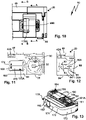
- the suction inlet 12 can be closed by a closure element 60 .
- the closure element 60 has a closure body 61 which can be inserted into the suction inlet 12 .
- the closure body 61 is therefore designed as a plug-in projection or plug-in body.
- the closure element 60 is movably mounted on the suction device housing 20 by means of a bearing 62 between a closed position V and a release position FS, the closure element 60 closing the suction inlet 12 in the closed position V and releasing it in the release position FS.
- the suction inlet 12 In the release position FS, the suction inlet 12 is free or open for arranging, in particular for inserting, the suction hose SL.
- the bearing 62 is a pivot bearing, for example, by means of which the closure element 60 is mounted pivotably about a pivot axis SC.
- the pivot axis SC is, for example, orthogonal to the top surface of the top 45A of the lid 44 or to the top surface of the suction device housing 20.
- the bearing 62 includes a bearing projection 63 on the closure element 60 which engages in a bearing receptacle 64 on the upper side 15 of the cover 44 .
- the bearing mount 64 is designed, for example, as a passage opening on the cover body or the cover wall 46 .
- the bearing projection 63 penetrates the passage opening. From the bearing projection 63, in particular at its free end area, there is a gripping contour 63A, for example a flange-like latching projection or the like, which grips the cover body or the top wall 46 on an underside of the cover 45 facing away from the top 15, so that the closure element 60 is captive, however is pivotally supported on the lid 45 or the suction device housing 20.
- the locking body 61 and the bearing projection 63 are arranged on an arm body 65 of the locking member 60 .
- the arm body 65 extends along a longitudinal axis L60 between the bearing projection 63 and the closure body 61, which are arranged at mutually opposite longitudinal end regions of the arm body 65.
- the arm body 65 is preferably plate-like and/or is designed in the manner of a strap.
- the cover 45 and thus the suction device housing 20 have a closure element receptacle 67 for the closure element 60 .
- the closure element receptacle 67 is designed as a depression on the upper side 45A of the cover 45 .
- a top 66 of the closure element 60 facing away from the top 45A of the cover 45 does not protrude in front of the top 45A of the cover 45 or is behind this top 45A, which is not shown in the exemplary embodiment, but is an option.
- the upper side 45A of the cover 45 is available for stacking another container or suction device housing 20 or also the container attachment 200, which will be explained below, without the closure element 60 representing an interfering contour.
- the closure element receptacle 67 is approximately triangular in plan view, for example, with the bearing 62 being arranged in one corner area of this triangle and the suction inlet 12 and a delivery receptacle 68 being arranged in the other corner areas.
- the supply receptacle 68 is also designed as a plug-in receptacle and has a peripheral wall 69 and a base 70 .
- the suction inlet 12 is designed as a plug-in receptacle with a peripheral wall 71 into which either the form-fit body 61 or the suction hose SL can be inserted.
- the locking body 61 protrudes in front of the arm body 65 in the manner of a locking projection and has a peripheral wall 72 and a bottom 73 .
- a handle portion 74 protrudes from the bottom 70 into an interior space delimited by the peripheral wall 72 and forms a handle 74A for grasping the closure element 60 .
- the closure body 61 preferably the closure element 60 as a whole, consists of a flexible material which, on the one hand, enables a press fit or tight fit in the suction inlet 12 or the delivery receptacle 68, but on the other hand also enables easy handling. This becomes clearer below:
- the arm body 65 is flexible so that the closure body 61 can be moved out of the suction inlet 12 or the delivery receptacle 68 while bending the arm body 65 .
- a correspondingly movable mounting or pivotable mounting on bearing 62 would also be possible in order to pivot closure element 60 not only back and forth about pivot axis SC between supply receptacle 68 and suction inlet 12, but also disengage or disengage transversely to pivot axis SC to pivot into engagement with the staging receptacle 68 and the suction inlet 12 .
- the closure element 60 can be movably mounted in the bearing receptacle 65 about a pivot axis SQ running transversely to the pivot axis SC, so that the closure element 60 can be moved away from the upper side 45A and disengaged from the suction inlet 12 or the delivery receptacle 68 .
- the bearing projection 63 can have a significantly smaller diameter than the bearing mount 64 and thus have a play of movement transversely to the pivot axis SC in the bearing mount 64.
- the handle portion 74 includes a base wall 75 from which side walls 76 project.
- the base wall 75 and side walls 76 form an approximately U-shaped or V-shaped configuration in cross section.
- the side walls 76 extend between the base wall 75 and the bottom 73 of the closure body 61.
- the base wall 75 and the bottom 70 are, for example, parallel to one another.
- the side walls 76 face the peripheral wall 72 of the closure body 61 .
- the side walls 76 are advantageously long enough for the handle section 74 to extend as far as the arm body 65 .
- the base wall 75 is approximately flush with the arm body 65 and/or with the top 45A of the lid 45. This makes it easier to grasp the handle 74A.
- a seal 77 On the outer periphery of the peripheral wall 72 of the closure body 61 is a seal 77, for example in the form of ribs or sealing projections 77A, which rests against the peripheral wall 71 or the peripheral wall 72 in a sealing fit or press fit when the closure body 61 is inserted into the delivery receptacle 68 or the Suction inlet 12 engages.
- the closure body 61 is held reliably in the provision receptacle 68 or the suction inlet 12 .
- the seal 77 ensures that the suction inlet 12 is sealed when no suction hose SL is inserted, so that no dust or other dirt from the dust collection container 36 or the dust collection space 21 can get into the environment. Nevertheless, the operator easily manages to actuate the closure element 60 from the supply receptacle 68 into the suction inlet 12 or vice versa.
- Insertion into the supply receptacle 68 or the suction inlet 12 is possible, for example, by pressing DV on the base wall 75 of the handle section 74.
- actuation from the suction inlet 12 or the delivery receptacle 68 is also easy to effect despite the press fit of the seal 77 on the peripheral wall 71 or 72 .
- the handle section 74 can namely be gripped with a clamp-like gripping movement and pulled out of the suction inlet 12 or the delivery receptacle 68 counter to the direction of actuation of the pressure actuation DV.
- the side walls 76 are parallel to one another or, as in the exemplary embodiment, are inclined at a small angle to one another, so that when an operator grips the handle section 74, he can grip the two side walls 76 like a clamp and move them towards one another, for example by means of a compressive load DO.
- sections of the peripheral wall 72 and thus the seal 77 are actuated away from the peripheral wall 71 or 72, so that the clamping fit of the closure body 61 on the delivery receptacle 68 or the suction inlet 12 is canceled or at least less tight.
- the side walls 76 yield under pressure when the operator acts on them and form recessed grips, so that handling is made even easier.
- rib structures or similar other gripping structures on the gripping section can also be used or handle of a closure member may be provided to facilitate handling.
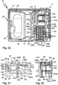
- the suction device 10 advantageously has a container attachment 200 or is compatible with a container attachment 200 .
- the container attachment 200 preferably has the same contour on its outer circumference as the suction device housing 20.
- the container attachment 200 can be stacked on the suction device 10, namely its suction device housing 20, and connected to it using the coupling means 58 already explained.
- the container attachment 200 includes a suction device housing 220 with a bottom wall 225, from which longitudinal side walls 226, 227, 228 and 229 protrude, which altogether delimit a receiving space 223 of the container attachment 200.
- the receiving space 223 is suitable for receiving the suction hose SL.
- a handle 224 receiving space 223 protrudes from the bottom wall 225 .
- the handle 224 is designed like a handle, so that the container attachment 200 attached to the suction device housing 20 serves as a carrying handle for carrying a stack 9 consisting of the suction device 10 and container attachment 200 .
- the container attachment 200 forms a stacking container 200A.
- the suction hose SL can be wound around the handle 224 so that it serves as a winding aid.
- a passage 222 for the suction hose SL is provided on the bottom wall 225 and is aligned with the suction inlet 12 when the container attachment 200 is attached to the suction device 10 . Furthermore, a lateral opening 221 for the suction hose SL is provided on the longitudinal side wall 28 .
- locking elements 251, 259 are provided as coupling means 58, which are structurally identical to and/or compatible with the locking elements 51 and 59.
- the locking element 51 of the suction device 10 can be brought into engagement with the locking element 259 are to form the stack 9 consisting of suction device 10 and stacked container attachment 200.
- Feet corresponding to feet 54 and 55 are not visible in the drawing on the side of the bottom wall 225 facing away from the receiving space 223, which can be brought into engagement with the receptacles 56 and 57 of the suction device housing 20, so that in combination with the interlocking locking elements 51 and 259 of the coupling means 58, a secure hold of the container attachment 200 on the suction device 10 can be effected in the direction of the stacking axis SR or in the stacking direction.
- the coupling means 58 also readily bring about a fixed connection between the container attachment 200 and the suction device housing 20 transversely to the stacking axis SR.
- Further containers for example containers for transporting tools, can be stacked or stacked underneath on the stack 9, which can be coupled to the container attachment 200 or the suction device housing 20 using coupling means that are compatible with the coupling means 58.
- the container attachment 200 can also be arranged under the suction device housing 20 and connected to it by means of the coupling means 58 to form a stack.
- another container attachment 200 not shown in the drawing, or another suction device 10, not shown, can be attached, for example, to the figure 6 upper container attachment 200 stacked and coupled to form a stack with this using coupling means that are compatible with the coupling means 58.
- the suction device 10 it would now be possible for the suction device 10 to be designed as a suction device that can be operated via a power supply network.
- the suction device 10 is not only extremely compact, but can also be used flexibly, in that the suction device 10 has a power supply device 80 to which energy stores 170, for example so-called battery packs, can be connected.
- energy stores 170 of the same type also referred to below as energy stores 170A, 170B, are provided for the power supply.
- the power supply device 80 comprises an energy storage receptacle 81 in the region of the suction turbine part 24.
- the energy storage receptacle 81 extends between the longitudinal side wall 28 and the partition wall 30 over almost the entire distance between the longitudinal side wall 28 and the partition wall 30, so that in the energy storage receptacle 81 two energy stores 170 can be arranged.
- the energy store receptacle 81 includes an insertion opening 82 through which the energy store 170 can be inserted into the energy store receptacle 81 .
- the insertion opening 82 is delimited by side walls 83, 84, which run next to the side wall 28 of the suction device housing 20 and the intermediate wall 30 of the suction device housing 20, in particular parallel to the same. Extending between the side walls 83 and 84 is a side wall or connecting wall 85 closer to the cover 45 and a side wall or thick wall 86 closer to the bottom wall 25 or formed by the bottom wall 25.
- the energy storage receptacle 81 is delimited by a bottom wall 87 which is the Insertion opening 82 is opposite.
- Interfaces 90 are arranged on the side walls 83, 84, with which the energy storage devices 170, which have energy storage device interfaces 190 matching the interfaces 90, can be connected.
- the interfaces 90, 190 include complementary longitudinal guide contours 91, 191, which can be inserted into one another along a plug-in axis SA.
- the longitudinal guide contours 91, 191 include longitudinal grooves and longitudinal projections that can engage in one another.
- the interfaces 90, 190 can be connected to one another in a form-fitting manner on the basis of the gripping contours 91A, 191A and the longitudinal guide contours 91, 191, apart from a sliding mobility along the respective plug-in axle SA.
- the interfaces 90, 190 include latching devices 92, 192 in order to latch the energy store 170 to the device interfaces 90.
- the latching devices 92 are designed, for example, as latching receptacles 93 into which the latching projections 193 of the latching devices 192 can engage in a latching manner, so that the energy stores 170 are held in a non-displaceable manner at the interfaces 90 with respect to the plug-in axle SA.
- the latching projections 193 are, for example, spring-loaded or resilient in the direction of their latching position in which they engage in the latching receptacles 93 and can be disengaged from the latching receptacles 93 against the aforementioned spring loading.
- the interfaces 90, 190 include contact arrangements 94, 194 to establish electrical connections between the energy store 170 and the suction device 10.
- the contact arrangements 94, 194 include, for example, energy supply contacts 95, 195 with different polarity, for example a positive potential and ground, as well as data contacts 96, 196 for data transmission between the suction device 10 and the respective energy store 170.
- Such a data transmission sees a digital bus data transmission, for example , especially with an I2C bus.
- Each energy storage device 171 has an energy storage device housing 171, which comprises longitudinal side walls 172 on its longitudinal sides 172A and end-side walls 173, 174 extending between these. Extending between the side walls 172-174 is a bottom wall 175 and, opposite this, an interface wall 176 on which the energy storage interface 190 is arranged.
- the interface wall 176 can have a stepped shape, so that, for example, the data contacts 196 a have a greater distance to the bottom wall 175 than the power supply contacts 195.
- the power supply contacts 195 and the data contacts 196 are arranged one behind the other in relation to the plug-in axle SA.
- the data contacts 196 are arranged at the front along the plug-in axis SA in the plug-in direction, i.e. closer to the end wall 173, while the supply contacts 195 are arranged in the plug-in direction along the plug-in axis SA at the rear, i.e. near the end side wall 174.
- the energy storage housing 171 has an interior 177 in which battery cells 178 are arranged, protected from environmental influences. However, the battery cells 178 heat up, for example, when charging or discharging, ie when the suction device 10 is operated using the energy store 170 .
- each energy store 170 has a fan 179 .
- the fan 179 generates a cooling air flow KL, which flows through an energy store inflow opening 180 into the interior space 177 and through an energy store outflow opening 181 out of the latter.
- the energy storage inflow opening 180 is arranged on the bottom wall 175 while the energy storage outflow opening 181 is arranged on the interface wall 176 .
- the energy storage inflow openings 180 and the energy storage outflow openings 181 are arranged on opposite longitudinal end regions of the energy storage 170, namely close to the end wall 174 and the end wall 173, so that the cooling air flow KL, e.g Cooling air flow KLB, a respective energy storage device 170 flows through, so to speak, from the back to the front with respect to the plug-in direction or plug-in axle SA.
- the cooling air flow KL e.g Cooling air flow KLB
- the device interfaces 90 are arranged on opposite sides of the energy storage receptacle 81, namely on the side walls 83 and 84. Accordingly, the energy stores 170 are accommodated in the energy store receptacle 81 with bottom walls 175 lying opposite one another.
- Operating elements 197 are provided on the longitudinal side walls 172 of the energy storage housing 171 to actuate the latching devices 192 . An operator can therefore grip the energy storage housing 171 laterally and/or in the manner of a clamp, so to speak, in order to simultaneously act on the two operating elements 197 arranged on the opposite longitudinal side walls 172, in order to disengage the locking projections 193 from the locking receptacles 93, so that the respective energy storage device 170 from the device interface 90 is removable.
- the receptacles 81 allow convenient handling, because between the connecting walls 85, 86 and the energy storage devices 170 inserted into the energy storage receptacle 81, there are operating spaces 88 and 89, into which an operator can actuate the operating elements 197, which, for example, have pressure surfaces or Have touch surfaces, can grasp.
- the control rooms 88 and 89 are, so to speak, uniform or continuous control rooms, because there is no separating component between the energy stores 170 accommodated in the energy store receptacle 81 .
- the energy stores 170 were accommodated in the energy store receptacle 81 with the energy store interfaces 190 facing one another, there would have to be a partition in the energy store receptacle 81 on which the device interfaces 90 are arranged.
- the operator can grasp the energy stores 170, for example on their longitudinal side walls 172, in order to remove them from the energy store receptacle 81.
- this also makes operation easier when inserting the energy storage device 170 into the energy storage device receptacle 81, because in this case too the operator can grasp the longitudinal side walls 172 in order to plug a respective energy storage device 170 into the device interface 90 assigned to it.
- the side walls 83, 84 are advantageously spaced apart from one another in such a way that the energy storage devices 170 connected to the device interfaces 90 are connected between their Bottom walls 175 a distance available, so that the cooling air flow KL can flow into the space between the bottom walls 175.
- Outflow openings 97 and 98 which are close to the device interfaces 90 and thus close to the energy storage outflow openings 181 of the energy storage 170 on the side walls 83 and 84 of the energy storage Recording 81 are arranged.
- the vents 97 and 98 are hereinafter referred to as receptacle vents because of their location in the energy storage receptacle 81 and are located close to the bottom wall 87 such that little or no heat builds up in the energy storage receptacle 81 .
- the outflow opening 98 opens directly into an intermediate space between the intermediate wall 30 and the filter element 13, so that a cooling air duct 99 is formed between the intermediate wall 30 and the filter element 13, which leads from the outflow opening 98 to the throughflow opening 32 on the intermediate wall 30 .
- a cooling air flow KLA of the energy store 170 arranged on the side wall 84 can flow out of the receiving outflow opening 98 and is sucked off by the suction turbine 11 via the cooling air duct 99 .
- the suction turbine 11 can even intensify the flow of cooling air KLA, which is indicated schematically by arrows.
- the energy store 170B can be cooled by a cooling air flow KLB, which can flow out of the energy store mount 81 through the outflow opening 97 .
- the receiving outflow opening 97 forms a duct inflow opening 97A for a cooling air duct 100.
- cooling air duct 100 does not lead directly to the through-flow opening 32, but instead opens into a further cooling air duct 101, which is used to cool further components of the suction device 10, for example for cooling an energization device 140 and also for a permanent cooling Cooling of the suction turbine 11.
- the suction turbine 11 is e.g.
- Such permanent cooling of the suction turbine 11 is particularly important when it cannot otherwise suck in sufficient air on the inflow side. Such a situation occurs, for example, when the suction inlet 12 is clogged or blocked, when the filter element 13 is no longer passable, when the dust collection space 21 is overcrowded, or the like.
- the suction turbine 11 is a so-called passage turbine.
- the suction turbine 11 has the suction turbine inflow opening 11A on its side facing the flow opening 32 and at least one, preferably several suction turbine outflow openings 11B on its side facing away from the flow opening 32 .
- a seal 11E is provided between the intermediate wall 30 on the one hand and the end face of the suction turbine 11 which faces the intermediate wall 30 and has the suction turbine inflow opening 11A on the other hand, so that it bears tightly against the intermediate wall 30 and the suction flow S can flow through the through-flow opening 32 can flow, but not in the suction turbine receiving space 31 in which the suction turbine 11 is arranged, flows.
- the suction turbine receiving space 31 is delimited by a side wall 31A in the area of the suction turbine outflow openings 11B.
- a suction turbine bearing element 11F is advantageously arranged, which is elastically flexible, so that this suction turbine bearing element 11F and the seal 11E support the suction turbine 11 in the suction device housing 20 in a vibration-damped manner.
- the suction turbine 11 has a fan 11C, shown schematically, and an electric drive motor 11D for driving the fan 11C.
- the drive motor 11D is cooled by the suction flow S during normal operation of the suction device 10, ie when the suction flow S is flowing.
- the suction device 10 has an energizing device 140 for energizing the suction turbine 11, in particular the drive motor 11D.
- the energizing device 140 includes, for example, one or more power electronic semiconductor elements 141, for example thyristors, MosFets or the like.
- the semiconductor elements 141 heat up during operation, namely when the suction turbine 11 is supplied with current.
- the energizing device 140 is arranged on a printed circuit board 104 which is arranged in a sandwich-like manner between the longitudinal side wall 28 and the side wall 83 of the energy storage receptacle 81 of the power supply device 80 .
- the printed circuit board 104 also partially extends into an intermediate space between the side wall 28 of the side wall 31A.
- the energizing device 140 is connected to the device interfaces 90A, 90B, in particular the energy supply contacts 95, by means of lines 143. Lines 144 connect the energizing device 140 to the suction turbine 11.
- the suction device 10 advantageously has a controller 150 .
- the controller 150 includes, for example, a processor 151 and memory 152, in which at least one control program 153 for controlling the suction turbine 11, for example, is provided.
- An operator can control the suction device 10 using operating elements 155 which are arranged on an operating panel 156 .
- the control panel 156 is arranged on the side wall 28 .
- the controller 150 is electrically connected to the operating elements 155 . With the operating elements 155, the suction device 10 can be switched on or off, for example. Furthermore, the power of the suction turbine 11 can be adjusted using the operating elements 155 .
- a display 157 is advantageously provided on the control panel 156, for example to display a status of the suction device 11.
- the controller 150 also generates heat, the dissipation of which is advantageously solved in the suction device 11, as will become clear below.
- the cooling air duct 101 is flow-connected to the receiving outflow opening 97 . Air can thus flow into the cooling air duct 101 via the intake/outflow opening 97, for example the cooling air flow KLB. However, the cooling air flow KLB has already been heated by the cooling of the energy store 170B.
- Ambient air that is to say generally cooler air, can flow into the cooling air duct 101 via a duct inflow opening 102 as a cooling air flow KLC.
- the channel inflow opening 102 is arranged, for example, close to the bottom wall 25 on an area of the longitudinal side wall 28 facing the bottom wall 25 .
- a protective grid 102A is advantageously arranged on the duct inflow opening 102 .
- the cooling air flow KLC flows via the duct inflow opening 102 into a duct section 103A of the cooling air duct 101, which runs between the printed circuit board 142 and the side wall 31A. Consequently, the cooling air flow KLC flows behind the printed circuit board 142 or the cooling air flow KLC flows past the printed circuit board 142 .
- the channel section 103A is selected such that the cooling air flow KLC essentially flows past the energizing device 140, ie in particular past the semiconductor elements 141, which become particularly warm during operation of the suction device 11. However, such heating and, in the worst case, heating is effectively counteracted using the cooling air flow KLC.
- the duct section 103A opens into a hose receptacle 104, in which a hose 110, thus a tubular body 110A for guiding cooling air, is accommodated.
- the hose receptacle 104 has, for example, a plug-in receptacle 105 into which the hose 110 is inserted, and an air-guiding surface 106 on a wall 107 .
- the cooling air flow KLC flowing out of the duct section 103A is guided into an inlet opening 111 of the hose 110 via the air guiding surface 106 .
- a plug-in stop 105A is advantageously located opposite the plug-in receptacle 105, against which a jacket of the cooling-air hose 110 can strike when it is inserted into the plug-in receptacle 105.
- the plug-in stop 105A is at a distance from the air-guiding surface 106 .
- the inlet opening 111 cannot be closed by the air-guiding surface 106 because of the plug-in stop 105A.
- the cooling air flow KLB can flow past the circuit board 142 and/or in a gap between the circuit board 142 and the cover wall 34 and also into the inlet opening 111 of the cooling air hose 110, so that the cooling air hose 110 flows both the cooling air flow KLB and the cooling air flow KLC in the direction of the channel outflow opening 108 leads.
- the cooling air hose 110 thus provides a common channel section 103B for the cooling air flows KLB and KLC.
- the cooling air hose 110 has a hose section 112 which carries the cooling air flow KLC and/or the cooling air flow KLB to the suction turbine receiving space 31 leads past to a channel outflow opening 108 which is arranged on the intermediate wall 30 and opens into the intermediate space between the intermediate wall 30 and the filter element 13 . There, the cooling air flow KLC and/or the cooling air flow KLB can flow in the direction of the flow opening 32 in order to be sucked off by the suction turbine 11 .
- the hose section 112 has an arcuate course. An end area 113 of the tube section 112 is held in the area of the duct outflow opening 108 in a receptacle 109 which is designed, for example, as a plug-in receptacle.
- cooling air flow KLC cools the power supply device 140, it also cools the suction turbine 11.
- the cooling air ducts 99 and 100 advantageously have smaller flow cross sections than the cooling air duct 101.
- the cooling air duct 101 namely cools the power electronics, e.g. the semiconductor elements 141. This measure helps to ensure that sufficient cooling air flows through the cooling air duct 101 and not, so to speak, past it through the cooling air ducts 99 and/or 100.
- the channel inflow openings 97A, 98A and 102 are permanently open.
- the cooling air flows KLA, KLB and KLC can thus contribute to the cooling of the suction turbine 11 in the long term.
- a sensor 154 is arranged on the suction turbine 11, the sensor signals from which are evaluated by the controller 150.
- the sensor 154 includes or is, for example, a temperature sensor and/or pressure sensor and/or flow sensor. Due to the permanent cooling of the suction turbine 11 using the cooling air flows KLA, KLB and KLC even when the suction flow S is interrupted is flowing or not, there is sufficient flow pressure at the sensor 154 so that it can report valid temperature signals to the controller 150 .
- controller 150 is designed to monitor a volume flow of suction flow S, for example using the at least one control program 153.
- the suction flow S has a volume flow VS, which has a pressure-dependent profile dependent on a pressure P.
- a characteristic VK of a volume flow of the suction flow S is in figure 28 drawn in schematically.
- the volume flow VS has values VS1, VS2 and VS3 in liters per second.
- the suction stream S should not fall below a minimum speed of 20 m/s, for example, so that a so-called dust class is maintained, according to which the suction device 10 always ensures adequate suction for this dust class.
- the required minimum speed of the suction flow S results in a minimum value VSmin for the volume flow of the suction flow S, which is approximately 10 l/s for a hose diameter of 27 mm for the suction hose SL.
- the controller 150 can calculate a characteristic VK of the volume flow of the Determine the intake flow S, because both the characteristic curve VK and the engine characteristics MK1 and MK2 in the area relevant for monitoring the volume flow or the flow rate of the intake flow S have a substantially constant, in particular substantially linear, course.
- the motor characteristics MK1 and MK2 depend on the voltages U1 and U2 with which the drive motor 11D is operated.
- the motor characteristics MK1 and MK2 are proportional to a current curve of the motor current Imot, with which the drive motor 11D is energized by the energizing device 140 .
- the controller 150 controls the energizing device 140 and receives feedback from it, for example, the motor voltage present, for example the motor voltages U1 and U2, and the respective motor current Imot for energizing the drive motor 11D.
- the controller 150 recognizes that the flow rate of the suction flow S is too low and issues a warning on the display 157, for example. In this case, as an alternative or in addition, the controller 150 can also output an acoustic warning to a loudspeaker or another acoustic output means 158 .
- a carrying strap 350 is advantageously suitable for comfortably transporting the suction device 10 or the stack 9 consisting of the suction device 10 and container attachment 200 or the container attachment 200 alone.
- the carrying strap 350 can be fastened either to the suction device 10 or to the container attachment 200.
- the carrying strap 350 has a fastening device 340 on each of its longitudinal end regions.
- the attachment devices 340 can be brought into engagement with attachment receptacles 300 of the suction device 10 or with attachment receptacles 320 of the container attachment 200 as required.
- the fastening devices 340 have base bodies 341 which are designed like plates.
- the base bodies 341 have rear gripping contours 342 on their long sides, which, in cooperation with rear gripping contours 302 of the fastening receptacle 300, serve as longitudinal guides along which the fastening devices 340 can be inserted into a respective fastening receptacle 300 along a plug-in axis S300.
- the base body 341 In the plug-in direction at the front with respect to a plug-in axle S300, the base body 341 has another rear gripping contour 343, the front section 343A of which strikes a stop 303 of the fastening receptacle 300 at the end of the plug-in movement along the plug-in axle S300.
- a bolt 304 of the fastening receptacle 300 which can be actuated using an actuating surface or actuating contour 305, can then reach its locking position, in which it reaches behind and/or over a gripping contour 344 of the fastening device 340.
- the bolt 304 is spring-loaded into its locking position, for example, and can be actuated against this spring loading by means of an actuating surface 305 with an unlocking actuation BE in the direction of its release position.
- the bolt 304 then disengages from the rear gripping contour 344 so that the fastening device 300 can be moved out of the fastening receptacle 300 designed as a plug-in receptacle.
- the rear gripping contour 343 and the rear gripping contour 344 extend between the rear gripping contours 342.
- the rear gripping contour 343 and the rear gripping contour 344 are arranged on opposite longitudinal end regions of the base body 341.
- the attachment mounts 320 are also designed as plug-in mounts.
- a fastening device can be placed in a respective fastening receptacle 320 340 are inserted along a stub axle S320 or are moved out of the mounting receptacle 320 along the stub axle S320.
- the rear gripping contours 343 and 344 of the fastening device 340 act as longitudinal guide contours which can engage with longitudinal guide contours or rear gripping contours 322 of the fastening receptacle 320 and guide the fastening device 340 along the quick-release axle S320.
- One of the rear gripping contours 342 of the fastening device 340 which is at the front in the insertion direction with respect to the stub axle S320, strikes a stop 323 on the bottom or end of the fastening receptacle 320 with respect to the stub axle S320.
- a gripping contour for receiving this gripping contour 342 can optionally be provided there.
- a bolt 346 of the fastening device 340 can then also engage with a locking contour 324 of a locking element 325 of the fastening receptacle 320, so that the fastening device 340 is locked in the fastening receptacle 320.
- the bolt 346 is designed as a resilient tongue or resilient element with respect to the base body 341 and has an actuating surface 345 with which it can be disengaged from the locking contour 324 of the fastening receptacle 320, which is indicated by an arrow or an actuation BE2 in the drawing is.
- the fastening devices 340 have strap mounts 347 for the carrying strap 350 .
- the carrying strap 350 can, for example, be pushed through a push-through opening 348 of a strap holder 347 and be held on the strap holder 347 in a frictionally engaged manner by means of appropriate sling measures.
- the attachment receptacles 320 of the container attachment 200 are located on the longitudinal side walls 228 and 229 in such a way that the carrying strap 340 can be brought into engagement with the attachment receptacles 320 bridging the receiving space 223 of the container attachment 200 .
- the stack 9 can, so to speak, hang down from the carrying strap 350 and be carried comfortably.
- the mounting receptacles 300 allow the suction device 10 to be carried in the manner of a shoulder bag.
- the fastening mounts 300 are arranged on one of the longitudinal side walls 26, 27, 28 or 29, specifically on the longitudinal side wall 26 in the exemplary embodiment. In any case, it is advantageous if the fastening mounts 300 are arranged on the narrow sides of the suction device housing 20 .
- fastening receptacle 300 is arranged in longitudinal end regions of the longitudinal side wall 26, i.e. close to the longitudinal side walls 28 and 29, so that the carrying strap 350 can serve as a strap or carrying handle suitable for hanging on a shoulder in a central section of the longitudinal side wall 26 .
Landscapes
- Engineering & Computer Science (AREA)
- Mechanical Engineering (AREA)
- Refuse Collection And Transfer (AREA)
- Cleaning In General (AREA)
- Manipulator (AREA)
- Filters For Electric Vacuum Cleaners (AREA)
- Packages (AREA)
Applications Claiming Priority (1)
| Application Number | Priority Date | Filing Date | Title |
|---|---|---|---|
| DE102021121709.1A DE102021121709A1 (de) | 2021-08-20 | 2021-08-20 | Sauggerät mit einem Verschlusselement |
Publications (2)
| Publication Number | Publication Date |
|---|---|
| EP4137024A1 true EP4137024A1 (fr) | 2023-02-22 |
| EP4137024B1 EP4137024B1 (fr) | 2024-07-17 |
Family
ID=82701725
Family Applications (1)
| Application Number | Title | Priority Date | Filing Date |
|---|---|---|---|
| EP22186385.5A Active EP4137024B1 (fr) | 2021-08-20 | 2022-07-22 | Appareil d'aspiration doté d'un élément de fermeture |
Country Status (8)
| Country | Link |
|---|---|
| US (1) | US20230073581A1 (fr) |
| EP (1) | EP4137024B1 (fr) |
| JP (1) | JP2023029314A (fr) |
| CN (1) | CN115919183A (fr) |
| AU (1) | AU2022209262A1 (fr) |
| DE (1) | DE102021121709A1 (fr) |
| DK (1) | DK4137024T3 (fr) |
| FI (1) | FI4137024T3 (fr) |
Families Citing this family (4)
| Publication number | Priority date | Publication date | Assignee | Title |
|---|---|---|---|---|
| DE102020215390A1 (de) * | 2020-12-04 | 2022-06-09 | Festool Gmbh | Tragbare Energiestation, Stapelanordnung und Verfahren zur Herstellung einer tragbaren Energiestation |
| USD1091990S1 (en) * | 2021-11-05 | 2025-09-02 | Festool Gmbh | Vacuum cleaner |
| US20250286351A1 (en) * | 2024-03-05 | 2025-09-11 | Hong Liu Co., Ltd. | Dust-proof filter structure for power supply panel |
| EP4681588A1 (fr) * | 2024-07-19 | 2026-01-21 | Hilti Aktiengesellschaft | Ensemble de soupape pour un dispositif d'aspiration |
Citations (3)
| Publication number | Priority date | Publication date | Assignee | Title |
|---|---|---|---|---|
| DE19753668A1 (de) * | 1997-05-12 | 1998-11-19 | Kwang Ju Electronics Co Ltd | Ferngesteuerter Staubsauger |
| EP1166705A1 (fr) * | 2000-06-14 | 2002-01-02 | WAP Reinigungssysteme GmbH & Co. | Procédé et dispositif pour nettoyer le filtre d'un aspirateur par impulsions de pression |
| DE102011015574A1 (de) * | 2011-03-30 | 2012-10-04 | Festool Gmbh | Sauggerät mit einem Motorsensor |
Family Cites Families (8)
| Publication number | Priority date | Publication date | Assignee | Title |
|---|---|---|---|---|
| US2780395A (en) * | 1952-11-14 | 1957-02-05 | Raymond M Schlabach | Container closure construction |
| JPH0355431Y2 (fr) * | 1986-01-17 | 1991-12-10 | ||
| JPH089609Y2 (ja) * | 1989-03-01 | 1996-03-21 | 株式会社ソキア | 測量機の壁面開口部の防水キャップ |
| DE4138223C1 (en) * | 1991-11-21 | 1993-02-18 | Alfred Kaercher Gmbh & Co, 7057 Winnenden, De | Vacuum cleaner with cleaning unit for filter - has separate filters closing through holes in parallel between dust collector and suction unit |
| US8833587B2 (en) * | 2011-12-12 | 2014-09-16 | Keepcup Pty Ltd. | Reusable beverage cup |
| DE102012100047B4 (de) | 2012-01-04 | 2021-12-09 | Miele & Cie. Kg | Akkutischsauger mit einem Staubrückhalteventil |
| DE102013012242A1 (de) | 2013-07-23 | 2015-01-29 | Festool Gmbh | Sauggerät mit einem Saugeinlass |
| US10494151B2 (en) * | 2014-04-01 | 2019-12-03 | Gpcp Ip Holdings Llc | Reclosable cup lid |
-
2021
- 2021-08-20 DE DE102021121709.1A patent/DE102021121709A1/de active Pending
-
2022
- 2022-07-22 FI FIEP22186385.5T patent/FI4137024T3/fi active
- 2022-07-22 DK DK22186385.5T patent/DK4137024T3/da active
- 2022-07-22 EP EP22186385.5A patent/EP4137024B1/fr active Active
- 2022-07-27 AU AU2022209262A patent/AU2022209262A1/en active Pending
- 2022-08-18 US US17/890,334 patent/US20230073581A1/en active Pending
- 2022-08-19 JP JP2022130921A patent/JP2023029314A/ja active Pending
- 2022-08-19 CN CN202210999379.6A patent/CN115919183A/zh active Pending
Patent Citations (3)
| Publication number | Priority date | Publication date | Assignee | Title |
|---|---|---|---|---|
| DE19753668A1 (de) * | 1997-05-12 | 1998-11-19 | Kwang Ju Electronics Co Ltd | Ferngesteuerter Staubsauger |
| EP1166705A1 (fr) * | 2000-06-14 | 2002-01-02 | WAP Reinigungssysteme GmbH & Co. | Procédé et dispositif pour nettoyer le filtre d'un aspirateur par impulsions de pression |
| DE102011015574A1 (de) * | 2011-03-30 | 2012-10-04 | Festool Gmbh | Sauggerät mit einem Motorsensor |
Also Published As
| Publication number | Publication date |
|---|---|
| AU2022209262A1 (en) | 2023-03-09 |
| JP2023029314A (ja) | 2023-03-03 |
| DE102021121709A1 (de) | 2023-02-23 |
| FI4137024T3 (fi) | 2024-09-27 |
| US20230073581A1 (en) | 2023-03-09 |
| EP4137024B1 (fr) | 2024-07-17 |
| DK4137024T3 (da) | 2024-08-19 |
| CN115919183A (zh) | 2023-04-07 |
Similar Documents
| Publication | Publication Date | Title |
|---|---|---|
| EP4137024B1 (fr) | Appareil d'aspiration doté d'un élément de fermeture | |
| EP4137029B1 (fr) | Appareil électrique, en particulier appareil d'aspiration ou machine-outil | |
| EP2637542B1 (fr) | Aspirateur | |
| DE102013012215B4 (de) | Sauggerät mit einem Hauptfilter | |
| EP2897513B1 (fr) | Aspirateur avec couvercle de batterie | |
| DE19831383A1 (de) | Handwerkzeugmaschine mit Staubabsaugung | |
| EP2895045A1 (fr) | Aspirateur | |
| DE202015004939U1 (de) | Staubsammler | |
| DE102016105330A1 (de) | Staubsammelvorrichtung mit einer Stützeinrichtung | |
| WO2022122280A1 (fr) | Dispositif d'aspiration comprenant au moins une zone de réception pour une batterie | |
| EP4137023B1 (fr) | Appareil d'aspiration | |
| EP4258965B1 (fr) | Appareil nettoyeur avec dispositf de batterie et dispositif de nettoyage de filtre | |
| DE102013012241A1 (de) | Sauggerät mit einem Schmutzsammelbehälter | |
| DE102013012242A1 (de) | Sauggerät mit einem Saugeinlass | |
| DE102016105331A1 (de) | Staubsammelvorrichtung mit einem Deckel für eine Hand-Werkzeugmaschine | |
| EP1429891B1 (fr) | Machine-outil dotee d'un compartiment a poussiere | |
| DE102021129515A1 (de) | Elektrisches Gerät, insbesondere Sauggerät oder Werkzeugmaschine | |
| EP0140234B1 (fr) | Aspirateur de poussières | |
| DE102023135330A1 (de) | Selbstfahrende und selbstlenkende Bodenreinigungsmaschine mit Tragegriff | |
| DE4042371A1 (de) | Akkustaubsauger | |
| EP3332684B1 (fr) | Dispositif d'aspiration doté d'un élément de filtrage | |
| DE102023135324A1 (de) | Selbstlenkende und selbstfahrende Bodenreinigungsmaschine mit Gehäuseteilen | |
| DE4030347A1 (de) | Akkustaubsauger | |
| DE9018055U1 (de) | Akkustaubsauger | |
| DE102016105457A1 (de) | Übertragungseinrichtung und damit ausgestatteter Stapelbehälter |
Legal Events
| Date | Code | Title | Description |
|---|---|---|---|
| PUAI | Public reference made under article 153(3) epc to a published international application that has entered the european phase |
Free format text: ORIGINAL CODE: 0009012 |
|
| STAA | Information on the status of an ep patent application or granted ep patent |
Free format text: STATUS: THE APPLICATION HAS BEEN PUBLISHED |
|
| AK | Designated contracting states |
Kind code of ref document: A1 Designated state(s): AL AT BE BG CH CY CZ DE DK EE ES FI FR GB GR HR HU IE IS IT LI LT LU LV MC MK MT NL NO PL PT RO RS SE SI SK SM TR |
|
| STAA | Information on the status of an ep patent application or granted ep patent |
Free format text: STATUS: REQUEST FOR EXAMINATION WAS MADE |
|
| 17P | Request for examination filed |
Effective date: 20230323 |
|
| RBV | Designated contracting states (corrected) |
Designated state(s): AL AT BE BG CH CY CZ DE DK EE ES FI FR GB GR HR HU IE IS IT LI LT LU LV MC MK MT NL NO PL PT RO RS SE SI SK SM TR |
|
| GRAP | Despatch of communication of intention to grant a patent |
Free format text: ORIGINAL CODE: EPIDOSNIGR1 |
|
| STAA | Information on the status of an ep patent application or granted ep patent |
Free format text: STATUS: GRANT OF PATENT IS INTENDED |
|
| INTG | Intention to grant announced |
Effective date: 20240222 |
|
| GRAS | Grant fee paid |
Free format text: ORIGINAL CODE: EPIDOSNIGR3 |
|
| GRAA | (expected) grant |
Free format text: ORIGINAL CODE: 0009210 |
|
| STAA | Information on the status of an ep patent application or granted ep patent |
Free format text: STATUS: THE PATENT HAS BEEN GRANTED |
|
| AK | Designated contracting states |
Kind code of ref document: B1 Designated state(s): AL AT BE BG CH CY CZ DE DK EE ES FI FR GB GR HR HU IE IS IT LI LT LU LV MC MK MT NL NO PL PT RO RS SE SI SK SM TR |
|
| REG | Reference to a national code |
Ref country code: CH Ref legal event code: EP |
|
| REG | Reference to a national code |
Ref country code: DE Ref legal event code: R096 Ref document number: 502022001245 Country of ref document: DE |
|
| P01 | Opt-out of the competence of the unified patent court (upc) registered |
Free format text: CASE NUMBER: APP_40161/2024 Effective date: 20240705 |
|
| REG | Reference to a national code |
Ref country code: IE Ref legal event code: FG4D Free format text: LANGUAGE OF EP DOCUMENT: GERMAN |
|
| REG | Reference to a national code |
Ref country code: DK Ref legal event code: T3 Effective date: 20240812 |
|
| REG | Reference to a national code |
Ref country code: FI Ref legal event code: FGE |
|
| REG | Reference to a national code |
Ref country code: NL Ref legal event code: FP |
|
| REG | Reference to a national code |
Ref country code: LT Ref legal event code: MG9D |
|
| PG25 | Lapsed in a contracting state [announced via postgrant information from national office to epo] |
Ref country code: PT Free format text: LAPSE BECAUSE OF FAILURE TO SUBMIT A TRANSLATION OF THE DESCRIPTION OR TO PAY THE FEE WITHIN THE PRESCRIBED TIME-LIMIT Effective date: 20241118 |
|
| PG25 | Lapsed in a contracting state [announced via postgrant information from national office to epo] |
Ref country code: PT Free format text: LAPSE BECAUSE OF FAILURE TO SUBMIT A TRANSLATION OF THE DESCRIPTION OR TO PAY THE FEE WITHIN THE PRESCRIBED TIME-LIMIT Effective date: 20241118 |
|
| PG25 | Lapsed in a contracting state [announced via postgrant information from national office to epo] |
Ref country code: NO Free format text: LAPSE BECAUSE OF FAILURE TO SUBMIT A TRANSLATION OF THE DESCRIPTION OR TO PAY THE FEE WITHIN THE PRESCRIBED TIME-LIMIT Effective date: 20241017 |
|
| PG25 | Lapsed in a contracting state [announced via postgrant information from national office to epo] |
Ref country code: GR Free format text: LAPSE BECAUSE OF FAILURE TO SUBMIT A TRANSLATION OF THE DESCRIPTION OR TO PAY THE FEE WITHIN THE PRESCRIBED TIME-LIMIT Effective date: 20241018 Ref country code: PL Free format text: LAPSE BECAUSE OF FAILURE TO SUBMIT A TRANSLATION OF THE DESCRIPTION OR TO PAY THE FEE WITHIN THE PRESCRIBED TIME-LIMIT Effective date: 20240717 |
|
| PG25 | Lapsed in a contracting state [announced via postgrant information from national office to epo] |
Ref country code: BG Free format text: LAPSE BECAUSE OF FAILURE TO SUBMIT A TRANSLATION OF THE DESCRIPTION OR TO PAY THE FEE WITHIN THE PRESCRIBED TIME-LIMIT Effective date: 20240717 |
|
| PG25 | Lapsed in a contracting state [announced via postgrant information from national office to epo] |
Ref country code: LV Free format text: LAPSE BECAUSE OF FAILURE TO SUBMIT A TRANSLATION OF THE DESCRIPTION OR TO PAY THE FEE WITHIN THE PRESCRIBED TIME-LIMIT Effective date: 20240717 |
|
| PG25 | Lapsed in a contracting state [announced via postgrant information from national office to epo] |
Ref country code: IS Free format text: LAPSE BECAUSE OF FAILURE TO SUBMIT A TRANSLATION OF THE DESCRIPTION OR TO PAY THE FEE WITHIN THE PRESCRIBED TIME-LIMIT Effective date: 20241117 |
|
| PG25 | Lapsed in a contracting state [announced via postgrant information from national office to epo] |
Ref country code: HR Free format text: LAPSE BECAUSE OF FAILURE TO SUBMIT A TRANSLATION OF THE DESCRIPTION OR TO PAY THE FEE WITHIN THE PRESCRIBED TIME-LIMIT Effective date: 20240717 |
|
| PG25 | Lapsed in a contracting state [announced via postgrant information from national office to epo] |
Ref country code: ES Free format text: LAPSE BECAUSE OF FAILURE TO SUBMIT A TRANSLATION OF THE DESCRIPTION OR TO PAY THE FEE WITHIN THE PRESCRIBED TIME-LIMIT Effective date: 20240717 Ref country code: RS Free format text: LAPSE BECAUSE OF FAILURE TO SUBMIT A TRANSLATION OF THE DESCRIPTION OR TO PAY THE FEE WITHIN THE PRESCRIBED TIME-LIMIT Effective date: 20241017 |
|
| PG25 | Lapsed in a contracting state [announced via postgrant information from national office to epo] |
Ref country code: RS Free format text: LAPSE BECAUSE OF FAILURE TO SUBMIT A TRANSLATION OF THE DESCRIPTION OR TO PAY THE FEE WITHIN THE PRESCRIBED TIME-LIMIT Effective date: 20241017 Ref country code: PL Free format text: LAPSE BECAUSE OF FAILURE TO SUBMIT A TRANSLATION OF THE DESCRIPTION OR TO PAY THE FEE WITHIN THE PRESCRIBED TIME-LIMIT Effective date: 20240717 Ref country code: NO Free format text: LAPSE BECAUSE OF FAILURE TO SUBMIT A TRANSLATION OF THE DESCRIPTION OR TO PAY THE FEE WITHIN THE PRESCRIBED TIME-LIMIT Effective date: 20241017 Ref country code: LV Free format text: LAPSE BECAUSE OF FAILURE TO SUBMIT A TRANSLATION OF THE DESCRIPTION OR TO PAY THE FEE WITHIN THE PRESCRIBED TIME-LIMIT Effective date: 20240717 Ref country code: IS Free format text: LAPSE BECAUSE OF FAILURE TO SUBMIT A TRANSLATION OF THE DESCRIPTION OR TO PAY THE FEE WITHIN THE PRESCRIBED TIME-LIMIT Effective date: 20241117 Ref country code: HR Free format text: LAPSE BECAUSE OF FAILURE TO SUBMIT A TRANSLATION OF THE DESCRIPTION OR TO PAY THE FEE WITHIN THE PRESCRIBED TIME-LIMIT Effective date: 20240717 Ref country code: GR Free format text: LAPSE BECAUSE OF FAILURE TO SUBMIT A TRANSLATION OF THE DESCRIPTION OR TO PAY THE FEE WITHIN THE PRESCRIBED TIME-LIMIT Effective date: 20241018 Ref country code: ES Free format text: LAPSE BECAUSE OF FAILURE TO SUBMIT A TRANSLATION OF THE DESCRIPTION OR TO PAY THE FEE WITHIN THE PRESCRIBED TIME-LIMIT Effective date: 20240717 Ref country code: BG Free format text: LAPSE BECAUSE OF FAILURE TO SUBMIT A TRANSLATION OF THE DESCRIPTION OR TO PAY THE FEE WITHIN THE PRESCRIBED TIME-LIMIT Effective date: 20240717 |
|
| PG25 | Lapsed in a contracting state [announced via postgrant information from national office to epo] |
Ref country code: LU Free format text: LAPSE BECAUSE OF NON-PAYMENT OF DUE FEES Effective date: 20240722 |
|
| PG25 | Lapsed in a contracting state [announced via postgrant information from national office to epo] |
Ref country code: LU Free format text: LAPSE BECAUSE OF NON-PAYMENT OF DUE FEES Effective date: 20240722 |
|
| PG25 | Lapsed in a contracting state [announced via postgrant information from national office to epo] |
Ref country code: SM Free format text: LAPSE BECAUSE OF FAILURE TO SUBMIT A TRANSLATION OF THE DESCRIPTION OR TO PAY THE FEE WITHIN THE PRESCRIBED TIME-LIMIT Effective date: 20240717 Ref country code: RO Free format text: LAPSE BECAUSE OF FAILURE TO SUBMIT A TRANSLATION OF THE DESCRIPTION OR TO PAY THE FEE WITHIN THE PRESCRIBED TIME-LIMIT Effective date: 20240717 |
|
| REG | Reference to a national code |
Ref country code: DE Ref legal event code: R097 Ref document number: 502022001245 Country of ref document: DE |
|
| PG25 | Lapsed in a contracting state [announced via postgrant information from national office to epo] |
Ref country code: BE Free format text: LAPSE BECAUSE OF NON-PAYMENT OF DUE FEES Effective date: 20240731 Ref country code: EE Free format text: LAPSE BECAUSE OF FAILURE TO SUBMIT A TRANSLATION OF THE DESCRIPTION OR TO PAY THE FEE WITHIN THE PRESCRIBED TIME-LIMIT Effective date: 20240717 Ref country code: MC Free format text: LAPSE BECAUSE OF FAILURE TO SUBMIT A TRANSLATION OF THE DESCRIPTION OR TO PAY THE FEE WITHIN THE PRESCRIBED TIME-LIMIT Effective date: 20240717 |
|
| PG25 | Lapsed in a contracting state [announced via postgrant information from national office to epo] |
Ref country code: CZ Free format text: LAPSE BECAUSE OF FAILURE TO SUBMIT A TRANSLATION OF THE DESCRIPTION OR TO PAY THE FEE WITHIN THE PRESCRIBED TIME-LIMIT Effective date: 20240717 |
|
| PG25 | Lapsed in a contracting state [announced via postgrant information from national office to epo] |
Ref country code: SK Free format text: LAPSE BECAUSE OF FAILURE TO SUBMIT A TRANSLATION OF THE DESCRIPTION OR TO PAY THE FEE WITHIN THE PRESCRIBED TIME-LIMIT Effective date: 20240717 |
|
| PLBE | No opposition filed within time limit |
Free format text: ORIGINAL CODE: 0009261 |
|
| STAA | Information on the status of an ep patent application or granted ep patent |
Free format text: STATUS: NO OPPOSITION FILED WITHIN TIME LIMIT |
|
| REG | Reference to a national code |
Ref country code: BE Ref legal event code: MM Effective date: 20240731 |
|
| 26N | No opposition filed |
Effective date: 20250422 |
|
| PGFP | Annual fee paid to national office [announced via postgrant information from national office to epo] |
Ref country code: FR Payment date: 20250618 Year of fee payment: 4 |
|
| PG25 | Lapsed in a contracting state [announced via postgrant information from national office to epo] |
Ref country code: IE Free format text: LAPSE BECAUSE OF NON-PAYMENT OF DUE FEES Effective date: 20240722 |
|
| PGFP | Annual fee paid to national office [announced via postgrant information from national office to epo] |
Ref country code: NL Payment date: 20250721 Year of fee payment: 4 |
|
| PG25 | Lapsed in a contracting state [announced via postgrant information from national office to epo] |
Ref country code: SE Free format text: LAPSE BECAUSE OF FAILURE TO SUBMIT A TRANSLATION OF THE DESCRIPTION OR TO PAY THE FEE WITHIN THE PRESCRIBED TIME-LIMIT Effective date: 20240717 |
|
| PGFP | Annual fee paid to national office [announced via postgrant information from national office to epo] |
Ref country code: FI Payment date: 20250725 Year of fee payment: 4 |
|
| PGFP | Annual fee paid to national office [announced via postgrant information from national office to epo] |
Ref country code: DK Payment date: 20250725 Year of fee payment: 4 Ref country code: DE Payment date: 20250618 Year of fee payment: 4 |
|
| PGFP | Annual fee paid to national office [announced via postgrant information from national office to epo] |
Ref country code: AT Payment date: 20251020 Year of fee payment: 4 |
|
| PGFP | Annual fee paid to national office [announced via postgrant information from national office to epo] |
Ref country code: IT Payment date: 20250731 Year of fee payment: 4 |
|
| PG25 | Lapsed in a contracting state [announced via postgrant information from national office to epo] |
Ref country code: IT Free format text: LAPSE BECAUSE OF NON-PAYMENT OF DUE FEES Effective date: 20240722 |
|
| PG25 | Lapsed in a contracting state [announced via postgrant information from national office to epo] |
Ref country code: CY Free format text: LAPSE BECAUSE OF FAILURE TO SUBMIT A TRANSLATION OF THE DESCRIPTION OR TO PAY THE FEE WITHIN THE PRESCRIBED TIME-LIMIT; INVALID AB INITIO Effective date: 20220722 |
|
| REG | Reference to a national code |
Ref country code: CH Ref legal event code: H13 Free format text: ST27 STATUS EVENT CODE: U-0-0-H10-H13 (AS PROVIDED BY THE NATIONAL OFFICE) Effective date: 20260224 |
|
| PG25 | Lapsed in a contracting state [announced via postgrant information from national office to epo] |
Ref country code: HU Free format text: LAPSE BECAUSE OF FAILURE TO SUBMIT A TRANSLATION OF THE DESCRIPTION OR TO PAY THE FEE WITHIN THE PRESCRIBED TIME-LIMIT; INVALID AB INITIO Effective date: 20220722 |
|
| PG25 | Lapsed in a contracting state [announced via postgrant information from national office to epo] |
Ref country code: IT Free format text: LAPSE BECAUSE OF NON-PAYMENT OF DUE FEES Effective date: 20240722 |
|
| PGRI | Patent reinstated in contracting state [announced from national office to epo] |
Ref country code: IT Effective date: 20240731 |
|
| PG25 | Lapsed in a contracting state [announced via postgrant information from national office to epo] |
Ref country code: CH Free format text: LAPSE BECAUSE OF NON-PAYMENT OF DUE FEES Effective date: 20250731 |