EP4137260A1 - Joint soudé à l'arc et procédé de soudage à l'arc - Google Patents
Joint soudé à l'arc et procédé de soudage à l'arc Download PDFInfo
- Publication number
- EP4137260A1 EP4137260A1 EP21788603.5A EP21788603A EP4137260A1 EP 4137260 A1 EP4137260 A1 EP 4137260A1 EP 21788603 A EP21788603 A EP 21788603A EP 4137260 A1 EP4137260 A1 EP 4137260A1
- Authority
- EP
- European Patent Office
- Prior art keywords
- weld bead
- ratio
- slag
- welding
- sub
- Prior art date
- Legal status (The legal status is an assumption and is not a legal conclusion. Google has not performed a legal analysis and makes no representation as to the accuracy of the status listed.)
- Pending
Links
Images
Classifications
-
- B—PERFORMING OPERATIONS; TRANSPORTING
- B23—MACHINE TOOLS; METAL-WORKING NOT OTHERWISE PROVIDED FOR
- B23K—SOLDERING OR UNSOLDERING; WELDING; CLADDING OR PLATING BY SOLDERING OR WELDING; CUTTING BY APPLYING HEAT LOCALLY, e.g. FLAME CUTTING; WORKING BY LASER BEAM
- B23K9/00—Arc welding or cutting
- B23K9/16—Arc welding or cutting making use of shielding gas
- B23K9/173—Arc welding or cutting making use of shielding gas and of a consumable electrode
-
- B—PERFORMING OPERATIONS; TRANSPORTING
- B23—MACHINE TOOLS; METAL-WORKING NOT OTHERWISE PROVIDED FOR
- B23K—SOLDERING OR UNSOLDERING; WELDING; CLADDING OR PLATING BY SOLDERING OR WELDING; CUTTING BY APPLYING HEAT LOCALLY, e.g. FLAME CUTTING; WORKING BY LASER BEAM
- B23K9/00—Arc welding or cutting
- B23K9/06—Arrangements or circuits for starting the arc, e.g. by generating ignition voltage, or for stabilising the arc
- B23K9/073—Stabilising the arc
-
- B—PERFORMING OPERATIONS; TRANSPORTING
- B23—MACHINE TOOLS; METAL-WORKING NOT OTHERWISE PROVIDED FOR
- B23K—SOLDERING OR UNSOLDERING; WELDING; CLADDING OR PLATING BY SOLDERING OR WELDING; CUTTING BY APPLYING HEAT LOCALLY, e.g. FLAME CUTTING; WORKING BY LASER BEAM
- B23K9/00—Arc welding or cutting
- B23K9/09—Arrangements or circuits for arc welding with pulsed current or voltage
-
- B—PERFORMING OPERATIONS; TRANSPORTING
- B23—MACHINE TOOLS; METAL-WORKING NOT OTHERWISE PROVIDED FOR
- B23K—SOLDERING OR UNSOLDERING; WELDING; CLADDING OR PLATING BY SOLDERING OR WELDING; CUTTING BY APPLYING HEAT LOCALLY, e.g. FLAME CUTTING; WORKING BY LASER BEAM
- B23K9/00—Arc welding or cutting
- B23K9/23—Arc welding or cutting taking account of the properties of the materials to be welded
-
- B—PERFORMING OPERATIONS; TRANSPORTING
- B23—MACHINE TOOLS; METAL-WORKING NOT OTHERWISE PROVIDED FOR
- B23K—SOLDERING OR UNSOLDERING; WELDING; CLADDING OR PLATING BY SOLDERING OR WELDING; CUTTING BY APPLYING HEAT LOCALLY, e.g. FLAME CUTTING; WORKING BY LASER BEAM
- B23K2103/00—Materials to be soldered, welded or cut
- B23K2103/02—Iron or ferrous alloys
- B23K2103/04—Steel or steel alloys
Definitions
- the present invention relates to an arc welded joint excellent in terms of corrosion resistance which can preferably be used for the chassis members of an automobile and the like and to an arc welding method for forming the joint.
- a rust prevention treatment such as chemical conversion coating and electrodeposition coating to achieve corrosion resistance after welding has been performed.
- a rust prevention treatment such as chemical conversion coating and electrodeposition coating to achieve corrosion resistance after welding has been performed.
- rust or corrosion is observed in a weld and a portion in the vicinity of the weld as time passes.
- electrodeposition coating as described above, corrosion tends to start at a weld, extends in the weld and a wide region surrounding the weld while being accompanied by coating film blister as time passes, and progresses also in the thickness direction.
- electrodeposition coating In the case where electrodeposition coating is performed, after chemical conversion coating (for example, a zinc phosphate treatment or the like) is first performed on a base steel sheet and a weld metal as a pretreatment to improve the adhesion property of an electrodeposition coating film to the base steel sheet and the weld metal, electrodeposition coating is performed.
- a zinc phosphate treatment which is widely used as an example of chemical conversion coating, is a technique in which zinc phosphate crystal grains are grown on the surface of the base steel sheet and the weld metal to improve the adhesion property of a coating film in electrodeposition coating.
- Examples of a conventionally known starting point in a weld at which corrosion occurs include the following.
- Patent Literature 1 discloses a technique in which, after arc welding has been performed and before electrodeposition coating is performed, a weld and a portion in the vicinity of the weld is subjected to a spraying treatment or an immersion treatment by using a non-oxidizing acidic solution having a pH of 2 or less at a temperature of 30°C to 90°C.
- This technique is a technique for removing the slag described in item (a) above, the welding fume described in item (b) above, and the oxide described in item (c) above by dissolving a weld bead and a steel sheet with the non-oxidizing solution.
- Patent Literature 1 since it is necessary to wash away the acidic solution before electrodeposition coating is performed, the manufacturing process of members becomes complex.
- a member having a desired shape is formed of steel sheets having various shapes which are overlapped and welded together, an acidic solution which is retained in gaps between the overlapped steel sheets causes severe corrosion.
- a large amount of acidic solution is used, breakdown and corrosion tend to occur in manufacturing equipment due to the equipment being exposed to a corrosive environment, and it is necessary to ensure the safety of operators by preventing fume from scattering.
- Patent Literature 2 discloses a technique in which the amounts of oxidizing gases (that is, CO 2 and O 2 ) contained in a gas for shielding a weld (hereinafter, referred to as "shielding gas") when arc welding is performed are decreased.
- shielding gas a gas for shielding a weld
- This technique is a technique for inhibiting the formation of slag when welding is performed, the oxidization of a welded heat affected zone, and the adhesion of welding fume.
- Patent Literature 3 discloses a technique in which the formation of slag is inhibited by decreasing the total of the contents of Si and Mn in a welding wire used in arc welding and the contents of Si and Mn in a steel sheet used.
- Patent Literature 4 discloses a technique in which, even in the case of a weld bead containing slag, welding fume, and oxides, a chemical conversion coating layer is sufficiently formed by controlling the chemical composition of a treatment solution used in chemical conversion coating.
- the formation of a chemical conversion coating layer is facilitated by performing a surface treatment with a surface conditioning solution containing a zinc phosphate colloid.
- a zinc phosphate treatment solution containing F in an amount of 100 mass ppm or more, slag, welding fume, and oxides are dissolved and removed, which results in an improvement in the adhesion property of an electrodeposition coating film.
- Patent Literature 4 since a zinc phosphate treatment solution containing fluorine, which is designated as a poisonous substance, is used, it is necessary to decrease the fluorine content in liquid waste generated from the treatment solution to a level satisfying environmental standards, when the liquid waste is discharged from a factory. Therefore, large liquid waste disposal equipment is necessary in addition to the manufacturing equipment for members.
- the present invention has been completed to solve the problems of the conventional techniques, and an object of the present invention is to provide an arc welded joint excellent in terms of corrosion resistance which can preferably be used for various steel-made members (for example, the chassis members of an automobile and the like) which are subjected to electrodeposition coating before use and an arc welding method for forming the joint.
- the present inventors conducted investigations regarding the reasons for a deterioration in corrosion resistance in a weld of a steel-made member which has been subjected to electrodeposition coating (hereinafter, referred to as "coated steel-made member").
- a deterioration in the corrosion resistance of the weld of the coated steel-made member is caused by slag and welding fume adhering to the weld (that is, a weld bead and a welded heat affected zone) and oxides formed on the surface of a steel sheet subjected to a high temperature due to arc welding.
- a zinc phosphate treatment is performed as chemical conversion coating before electrodeposition coating is performed on a member which has been manufactured by a steel sheet subjected to work, the steel sheet is dissolved due to the etching function of the zinc phosphate treatment solution.
- the present inventors conducted investigations regarding a technique with which it is possible to improve corrosion resistance by densely precipitating zinc phosphate crystal grains on a weld. As a result, it was found that, to improve the corrosion resistance of the weld, decreasing the amount of slag adhering to the weld is most effective.
- a member manufactured by using a high strength steel sheet and a high strength welding wire since there is an increase in the contents of Si, Mn, Ti, and the like due to the member having a high alloy chemical composition, there is a problem of an increase in the amount of slag formed in the weld.
- the present invention is an arc welded joint, having a slag-coverage area ratio S RATIO (%) of 15% or less, wherein S RATIO is calculated by using equation (1), where an area of a surface of a weld bead formed by performing arc welding on a steel sheet is defined as a weld bead surface area S BEAD (mm 2 ) and, of the weld bead surface area S BEAD , an area of a region covered with slag is defined as a slag surface area S SLAG (mm 2 ), and having a weld bead width ratio W RATIO (%) of 60% or more, wherein W RATIO is calculated by using equation (2) from a maximum value W MAX (mm) and a minimum value W MIN (mm) of a weld bead width in a direction perpendicular to a welding line of the weld bead.
- S RATIO is calculated by using equation (1), where an area of a surface of a we
- a cleaning region in which oxides formed on a surface of the steel sheet are removed due to formation of a cathode spot when the arc welding is performed, be formed so as to be adjacent to a weld bead toe and that a minimum value M MIN (mm) of a distance M (mm) in the direction perpendicular to the welding line between an outer edge of the cleaning region and the weld bead toe (hereinafter, referred to as "cleaning width") be 0.5 mm or more.
- the present invention is an arc welding method for manufacturing an arc welded joint, the arc welded joint having a slag-coverage area ratio S RATIO (%) of 15% or less, wherein S RATIO is calculated by using equation (1), where an area of a surface of a weld bead formed by performing arc welding on a steel sheet is defined as a weld bead surface area S BEAD (mm 2 ) and, of the weld bead surface area S BEAD , an area of a region covered with slag is defined as a slag surface area S SLAG (mm 2 ), and having a weld bead width ratio W RATIO (%) of 60% or more, wherein W RATIO is calculated by using equation (2) from a maximum value W MAX (mm) and a minimum value W MIN (mm) of a weld bead width in a direction perpendicular to a welding line of the weld bead.
- S RATIO is calculated by using equation
- the arc welding be performed with reverse polarity as in a case of common CO 2 welding and MAG welding, that a cleaning region, in which oxides formed on a surface of the steel sheet are removed due to formation of a cathode spot, which is an electron-emitting source, be formed so as to be adjacent to a weld bead toe, and that a minimum value M MIN (mm) of the cleaning width M (mm) be 0.5 mm or more.
- Ar gas be used as a shielding gas.
- a short circuit intermittently occur between the steel sheet and a welding wire and that such a short circuit occur at an average short circuit frequency F AVE (Hz) of 20 Hz to 300 Hz with a maximum short circuit cycle T CYC (s) of 1.5 s or less.
- pulse current be used as welding current of the arc welding and that X (A ⁇ s/m) calculated by using equation (3) from peak current I PEAK (A), base current I BASE (A), peak time t PEAK (ms), rise time t UP (ms), and fall time t DOWN (ms) of the pulse current and a distance L (mm) between the steel sheet and a contact tip satisfy a relational expression 50 ⁇ X ⁇ 250.
- a solid wire may be used as the welding wire.
- the cleaning region described above is a region in which, by performing arc welding with the steel sheet being set at the cathode and with the welding wire being set at the anode (that is, with so-called reverse polarity), a cathode spot, which is an electron-emitting source, is formed on the steel sheet, and in which a phenomenon (so-called cleaning), in which oxides formed on the surface of the steel sheet are removed due to electron emission occurring in such a manner, occurs.
- "s" used in the unit of X (A ⁇ s/m) denotes "seconds”
- the present invention since it is possible to improve the corrosion resistance of the welds of various kinds of members such as chassis members, it is possible to improve the rust prevention performance of members made of a high strength steel sheet and members which are used in a strongly corrosive environment. According to the present invention, it is possible to manufacture various kinds of members by using a high strength steel sheet having a tensile strength of, for example, 440 MPa or higher (for example, a steel sheet of a 440 MPa class, a steel sheet of a 590 MPa class, and a steel sheet of a 980 MPa class) and to improve the corrosion resistance thereof, which has a significant effect on the industry. In addition, by using a high strength steel sheet, it is also possible to decrease the thickness of the members.
- a high strength steel sheet having a tensile strength of, for example, 440 MPa or higher for example, a steel sheet of a 440 MPa class, a steel sheet of a 590 MPa class, and a steel sheet of
- the present invention may be used for not only lap fillet welding but also various welding techniques (for example, butt welding and the like).
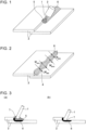
- Fig. 1 illustrates one example in which two steel sheets are welded.
- a welding wire 1 which is continuously fed through the center of a welding torch 2 from the welding torch 2 to steel sheets (base materials) 3 (in detail, for example, a welding line corresponding to the corner of a step formed by two steel sheets 3 as base materials, overlapped with each other), and the steel sheets 3 as electrodes, a welding voltage is applied from a welding power source (not illustrated).
- a portion of shielding gas (not illustrated) fed from inside the welding torch 2 being ionized to form plasma, an arc 5 is formed between the welding wire 1 and the steel sheets 3.
- the other portion of the shielding gas which is not ionized and which flows from the welding torch 2 to the steel sheets 3, has a role in sealing the arc 5 and a weld pool (not illustrated in Fig. 1 ), which is formed due to the steel sheet 3 being melted, from outside air.
- the front end of the welding wire 1 is melted by the heat of the arc 5 to form a droplet, and the droplet is transported to the weld pool by an electromagnetic force, gravity, and the like.
- the weld pool is solidified to form a weld bead 6 on the rear side of the welding line. Consequently, the joining of the two steel sheets is completed.
- a welding wire 1 and a steel sheet 3 to which non-ferrous metals such as Si, Mn, Ti, and the like are added as deoxidizing agents are used. That is, by discharging oxygen which is generated due to a reaction expressed by formula (4) or formula (5) in the form of slag formed of SiO 2 , MnO, TiO 2 , and the like, a reaction between oxygen and iron is inhibited.
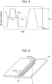
- Slag which has been discharged to the surface of the weld pool 8 is aggregated in a subsequent cooling process, allowed to adhere to the surface of the weld bead 6 and a weld bead toe 9 (that is, a weld bead) (refer to Fig. 5 ), and solidified.
- a chemical conversion coating layer is not sufficiently formed even when chemical conversion coating is performed on the arc welded joint.
- slag is a nonconductor, it is difficult to form a uniform electrodeposition coating film. Therefore, it is necessary to inhibit the formation of slag while preventing a deterioration in the mechanical properties of a weld metal by using a welding wire 1 and a steel sheet 3 containing deoxidizing agents.
- weld bead toe 9 and the weld bead start/finish end portions 10 will be described with reference to Fig. 5 .
- the term "weld bead start/finish end portions” denotes a weld bead start end portion and a weld bead finish end portion.
- weld bead start end portion denotes a region of the weld bead from a weld bead start end position (welding start position) to a point on the welding line located 15 mm toward a weld bead finish end position (welding finish position), and the term “weld bead finish end portion” denotes a region of the weld bead from the weld bead finish end position to a point on the welding line located 15 mm toward the weld bead start end position.
- welding bead toe denotes a boundary in a direction perpendicular to the welding line of the weld bead between the weld metal and the unmelted base steel sheet.
- a shielding gas containing mainly Ar gas by using a shielding gas containing mainly Ar gas, there is a decrease in the amount of O 2 and CO 2 mixed in, which results in the formation of slag being inhibited.
- a shielding gas containing mainly Ar gas when the area of the surface of the weld bead 6 is defined as a weld bead surface area S BEAD (mm 2 ) and, of the weld bead surface area S BEAD , the area of the region covered with slag is defined as a slag surface area S SLAG (mm 2 ), a slag-coverage area ratio S RATIO (%) calculated by using equation (1) is set to be 15% or less.
- the slag-coverage area ratio S RATIO be 9% or less or more preferably 5% or less.
- the slag-coverage area ratio S RATIO be as small as possible, there is no particular limitation on the lower limit of the slag-coverage area ratio S RATIO . It is preferable that the slag-coverage area ratio S RATIO be 0.1% or more.
- S RATIO 100 ⁇ S SLAG / S BEAD
- a weld bead width ratio W RATIO (%) calculated by using equation (2) from the maximum value W MAX (mm) and the minimum value W MIN (mm) of a weld bead width (refer to Fig. 2 ) in a direction perpendicular to a line parallel to the welding direction of the weld bead 6 (hereinafter, referred to as "welding line") is set to be 60% or more.
- the weld bead width ratio W RATIO be 70% or more or more preferably 80% or more.
- arc welding be performed with the steel sheet 3 being set at the cathode and with the welding wire 1 being set at the anode (that is, with so-called reverse polarity).
- reverse polarity since a cathode spot, which is an electron-emitting source, is formed on the steel sheet 3, a region 4 (a so-called cleaning region), in which oxides (for example, mill scale formed in the manufacturing process of the steel sheet 3, oxides formed due to heat input when welding is performed, and the like) formed on the surface of the steel sheet 3 are removed, is formed.
- the minimum value M MIN (mm) of the cleaning width M (mm) be 0.5 mm or more, more preferably 2.0 mm or more, or even more preferably 4.0 mm or more.
- the maximum value M MAX (mm) of the cleaning width M (mm) be 8.0 mm or less.
- the welding wire 1 is set at the anode, and the steel sheet 3 is set at the cathode. Then, as a result of a welding voltage being applied through the welding wire 1, which is continuously fed through the center of the welding torch 2 to the steel sheets 3, a portion of shielding gas, which is fed from inside the welding torch 2, is ionized to form plasma. Consequently, the arc 5 is formed between the welding wire 1 and the steel sheets 3.
- the remaining shielding gas that is, the portion of the gas, which is not ionized and which flows from the welding torch 2 to the steel sheets 3) seals the arc 5, the molten metal 7, and the weld pool 8 from outside air (refer to Fig. 3 ). Consequently, oxygen incorporation (that is, the formation of slag) and nitrogen incorporation (that is, the formation of blow holes) are prevented.
- the front end of the welding wire 1 is melted by the heat of the arc 5 to form molten metal 7, and the droplet of the molten metal 7 is transported to the weld pool 8 by an electromagnetic force, gravity, and the like.
- a state in which the molten metal 7 is separated from the weld pool 8 (refer to Fig. 3(a) ) and a state in which the molten metal 7 is in contact with the weld pool 8, that is, a short circuit state, (refer to Fig. 3(b) ) are alternately repeated regularly.
- the weld pool 8 is solidified to form a weld bead 6 on the rear side of the welding line.
- the chemical composition of the Ar gas described above is a chemical composition containing Ar in an amount of 99.0% or more in terms of volume fraction.
- Such a shielding gas containing mainly the Ar gas described above is also referred to as an "Ar shielding gas".
- the cycle at which a short circuit occurs between the welding wire 1 and the steel sheet 3 (hereinafter, referred to as "short circuit cycle") and the frequency with which such a short circuit occurs (hereinafter, referred to as “short circuit frequency”) are specified in the present invention.
- the maximum value of the short circuit cycle T CYC (s) be 1.5 s or less and that the average value of the short circuit frequency (average short circuit frequency) F AVE (Hz) be 20 Hz to 300 Hz.
- weld bead 6 By specifying the maximum value of the short circuit cycle and the average short circuit frequency to realize stable droplet transfer, since it is possible not only to inhibit the formation of slag but also to realize stable arc discharge, it is possible to form a weld bead 6 in which the slag-coverage area ratio S RATIO and the weld bead width ratio W RATIO are within the ranges described above.
- the weld pool 8 becomes unstable. Specifically, in the case where the average short circuit frequency F AVE is less than 20 Hz, large droplets are transferred to the weld pool 8, or droplet transfer modes other than a short circuit transfer mode (for example, streaming transfer mode and the like) are mixed irregularly. In addition, in the case where the average short circuit frequency F AVE is more than 300 Hz, although the size of droplets is small, arc reignition due to a short circuit occurs excessively often. For such reasons, in any of such cases, since the weld pool 8 is disturbed, it is difficult to eliminate the meandering or wavy shape of the weld bead.
- the average short circuit frequency F AVE to be 20 Hz to 300 Hz, it is possible to control the volume of a droplet which is transferred to the weld pool 8 in one short circuit cycle to be about the same as that of a sphere having a diameter equal to that of the welding wire 1. As a result, it is possible to stabilize droplet transfer.
- the average short circuit frequency F AVE be 35 Hz or more or even more preferably 50 Hz or more.
- the average short circuit frequency F AVE be 250 Hz or less or even more preferably 200 Hz or less.
- the weld bead width and a penetration depth become unstable. That is, by controlling the maximum short circuit cycle T CYC to be 1.5 s or less, it is possible to form a weld bead 6 having a good shape.
- maximum short circuit cycle T CYC denotes the maximum value of a short circuit cycle in a welding pass for forming an arc welded joint. This means that any of the short circuit cycles in a welding pass does not exceed 1.5 s.
- the average short circuit frequency F AVE and the maximum short circuit cycle T CYC as described above, regular and stable droplet transfer is possible in arc welding utilizing an Ar shielding gas.
- the maximum short circuit cycle T CYC be 1.0 s or less or even more preferably 0.2 s or less.
- the maximum short circuit cycle T CYC be within a range in which the average short circuit frequency F AVE becomes 300 Hz or less, and it is preferable that the maximum short circuit cycle T CYC be 0.004 s or more.
- examples of preferable welding conditions include welding current: 150 A to 300 A, arc voltage: 20 V to 35 V, Ar gas flow rate: 15 Liter/min to 25 Liter/min, distance L between the steel sheet 3 and a contact tip (hereinafter, referred to as "CTWD"): 5 mm to 30 mm, and the like.
- CTWD contact tip
- a peak current is defined as I PEAK (A)
- a base current is defined as I BASE (A)
- a peak time is defined as t PEAK (ms)
- a rise time is defined as t UP (ms)
- a fall time is defined as t DOWN (ms)
- CTWD is defined as L (mm)
- X I PEAK ⁇ t PEAK / L + I PEAK + I BASE ⁇ t UP + t DOWN / 2 ⁇ L
- the value of X (A ⁇ s/m) calculated by using equation (3) is excessively small, there may be a case where the arc 5 sways and/or droplet transfer becomes unstable.
- the value of X is excessively large, there may be a case where the welding wire 1 plunges in the weld pool 8 or a case where a grown droplet flies apart at the time of a short circuit, resulting in a deterioration in weld bead shape, spatter adhesion, and the like. Therefore, it is preferable that the value of X satisfy the relational expression 50 ⁇ X ⁇ 250 or more preferably 60 ⁇ X ⁇ 230.
- the value of X be 80 or more and that the value of X be 200 or less.
- "s” used in the unit of X denotes “seconds”
- the value of the distance L between the steel sheet 3 and the contact tip is excessively small, since severe wear occurs in the welding torch 2, welding becomes unstable. In the case where the value of the distance L between the steel sheet 3 and the contact tip is excessively large, the arc 5 sways. Therefore, it is preferable that the value of L be 5 mm to 30 mm or more preferably 8 mm to 20 mm.
- I PEAK In the case where the value of I PEAK is excessively small, since it is not possible to achieve sufficient heat input, there is a deterioration in weld bead shape. In the case where the value of I PEAK is excessively large, burn through occurs, and there is an increase in the number of spatters. Therefore, it is preferable that I PEAK be 250 A to 600 A. It is more preferable that I PEAK be 400 A or more and that I PEAK be 500 A or less.
- I BASE In the case where the value of I BASE is excessively small, arc becomes unstable. In the case where the value of I BASE is excessively large, burn through occurs. Therefore, it is preferable that I BASE be 30 A to 120 A. It is more preferable that I BASE be 40 A or more and that I BASE be 100 A or less.
- t PEAK In the case where the value of t PEAK is excessively small, it is not possible to achieve sufficient heat input. In the case where the value of t PEAK is excessively large, burn through occurs. Therefore, it is preferable that t PEAK be 0.1 ms to 5.0 ms. It is more preferable that t PEAK be 1.0 ms or more and that t PEAK be 4.5 ms or less.
- each of t UP and t DOWN be 0.1 ms to 3.0 ms. It is more preferable that each of t UP and t DOWN be 0.5 ms or more and that each of t UP and t DOWN be 2.5 ms or less.
- t BASE When the base time of the pulse current is defined as t BASE (ms), although t BASE is not used in equation (3), which is used for calculating the value of X, in the case where t BASE is excessively small, there is an excessive decrease in the size of a droplet. In the case where t BASE is excessively large, there is an excessive increase in the size of a droplet. In any of such cases, welding becomes unstable. Therefore, it is preferable that t BASE be 0.1 ms to 10.0 ms. It is more preferable that t BASE be 1.0 ms or more and that t BASE be 8.0 ms or less.
- a short circuit it is not necessary that a short circuit occur in every cycle of the pulse current. It is sufficient that a short circuit occur once in one to several pulses. In addition, as long as a short circuit occurs once in one to several pulses, there is no particular limitation on the pulse frequency of the pulse current.
- the purpose of using the pulse current is (1) to promote the stable growth of the droplet in the base time while inhibiting the arc from swaying by applying lower current and (2) to promote a short circuit in the peak time and the fall time by pushing down the grown droplet to the weld pool by using electromagnetic force and the shearing force of the Ar shielding gas without separating the grown droplet from the wire.
- the solid wire which can preferably be used in the present invention has a wire chemical composition containing C: 0.020 mass% to 0.250 mass%, Si: 0.05 mass% to 1.50 mass%, Mn: 0.50 mass% to 3.0 mass%, P: 0.020 mass% or less, S: 0.03 mass% or less, and a balance of Fe and incidental impurities. It is preferable that the diameter of the solid wire be 0.4 mm to 2.0 mm.
- cation electrodeposition coating was performed under a condition in which the film thickness on the flat base steel sheet other than the weld was 15 ⁇ m. Subsequently, a corrosion test in accordance with SAE J 2334 was performed for 60 cycles.
- the weld bead surface area S BEAD and the slag surface area S SLAG were derived by taking the image of the surface of the region of the weld bead 6 excluding the weld bead start/finish end portions 10 (having a length of 15 mm each) from directly above and by measuring the projected areas of the weld bead and slag viewed from above.
- the image of the surface of the full length of the weld bead 6 excluding the weld bead start/finish end portions 10 was taken.
- the slag-coverage area ratio S RATIO was derived by using equation (1) above from the weld bead surface area S BEAD and the slag surface area S SLAG derived as above.
- the derived slag-coverage area ratio S RATIO is given in Table 3.
- the maximum value W MAX and minimum value W MIN of the weld bead width were measured by taking the image of the surface of the region of the weld bead 6 excluding the weld bead start/finish end portions 10 (having a length of 15 mm each) and by analyzing the taken image.
- the image of the surface of the full length of the weld bead 6 excluding the weld bead start/finish end portions 10 was taken.
- weld bead width ratio W RATIO was derived by using equation (2) above from the maximum value W MAX and minimum value W MIN of the weld bead width measured as above.
- the derived weld bead width ratio W RATIO is given in Table 3.
- the maximum value M MAX and the minimum value M MIN of the cleaning width were measured by taking the image of the surface of the region of the weld bead 6 excluding the weld bead start/finish end portions 10 (having a length of 15 mm each) and by analyzing the taken image.
- the image of the surface of the full length of the weld bead excluding the weld bead start/finish end portions 10 was taken.
- reference sign A denotes a case of "a maximum corrosion width H MAX from the weld bead toe of less than 3.0 mm.
- Reference sign B denotes a case of "a maximum corrosion width H MAX from the weld bead toe of 3.0 mm or more and less than 4.5 mm.
- Reference sign C denotes a case of "a maximum corrosion width H MAX from the weld bead toe of 4.5 mm or more and less than 6.0 mm”.
- Reference sign F denotes a case of "a maximum corrosion width H MAX from the weld bead toe of 6.0 mm or more”.
- the rank denoted by reference sign A is the highest followed by those denoted by reference signs B and C in this order, and the rank denoted by reference sign F is the lowest.
- weld bead start end portion denotes a region of the weld bead from a weld bead start end position (welding start position) to a point on the welding line located 15 mm toward a weld bead finish end position (welding finish position)
- weld bead finish end portion denotes a region of the weld bead from the weld bead finish end position to a point on the welding line located 15 mm toward the weld bead start end position.
- welding bead toe denotes a boundary in a direction perpendicular to the welding line of the weld bead between the weld metal and the unmelted base steel sheet.
- Evaluation A denotes a case of a maximum corrosion width H MAX from the weld bead toe of less than 3.0 mm.
- B denotes a case of a maximum corrosion width H MAX from the weld bead toe of 3.0 mm or more and less than 4.5 mm.
- C denotes a case of a maximum corrosion width H MAX from the weld bead toe of 4.5 mm or more and less than 6.0 mm.
- F denotes a case of a maximum corrosion width H MAX from the weld bead toe of 6.0 mm or more.
- [Table 4] Wire Code Chemical Composition of Welding Wire (mass%) C Si Mn P S W1 0.068 0.57 1.06 0.006 0.006 W2 0.054 0.90 1.37 0.005 0.015
Landscapes
- Engineering & Computer Science (AREA)
- Physics & Mathematics (AREA)
- Plasma & Fusion (AREA)
- Mechanical Engineering (AREA)
- Chemical & Material Sciences (AREA)
- Materials Engineering (AREA)
- Arc Welding In General (AREA)
- Arc Welding Control (AREA)
- Nonmetallic Welding Materials (AREA)
Applications Claiming Priority (2)
| Application Number | Priority Date | Filing Date | Title |
|---|---|---|---|
| JP2020072716 | 2020-04-15 | ||
| PCT/JP2021/010961 WO2021210335A1 (fr) | 2020-04-15 | 2021-03-18 | Joint soudé à l'arc et procédé de soudage à l'arc |
Publications (2)
| Publication Number | Publication Date |
|---|---|
| EP4137260A1 true EP4137260A1 (fr) | 2023-02-22 |
| EP4137260A4 EP4137260A4 (fr) | 2023-10-11 |
Family
ID=78083828
Family Applications (1)
| Application Number | Title | Priority Date | Filing Date |
|---|---|---|---|
| EP21788603.5A Pending EP4137260A4 (fr) | 2020-04-15 | 2021-03-18 | Joint soudé à l'arc et procédé de soudage à l'arc |
Country Status (7)
| Country | Link |
|---|---|
| US (1) | US20230132518A1 (fr) |
| EP (1) | EP4137260A4 (fr) |
| JP (1) | JP7238990B2 (fr) |
| KR (1) | KR102735015B1 (fr) |
| CN (1) | CN115427179B (fr) |
| MX (1) | MX2022012761A (fr) |
| WO (1) | WO2021210335A1 (fr) |
Families Citing this family (10)
| Publication number | Priority date | Publication date | Assignee | Title |
|---|---|---|---|---|
| JP7741377B2 (ja) * | 2021-10-29 | 2025-09-18 | 日本製鉄株式会社 | 溶接継手、溶接継手の製造方法、自動車部品、及び建材部品 |
| JP2023166120A (ja) * | 2022-05-09 | 2023-11-21 | 日本製鉄株式会社 | アーク溶接継手、自動車部品、及びアーク溶接継手の製造方法 |
| WO2023243728A1 (fr) * | 2022-06-17 | 2023-12-21 | 日本製鉄株式会社 | Procédé de fabrication d'un joint soudé à l'arc, joint soudé à l'arc et composant automobile |
| JP7435931B1 (ja) * | 2022-10-31 | 2024-02-21 | Jfeスチール株式会社 | ガスシールドアーク溶接方法および溶接継手の製造方法 |
| EP4570410A4 (fr) * | 2022-10-31 | 2025-11-26 | Jfe Steel Corp | Procédé de soudage à l'arc de filet de recouvrement, et procédé de production de joint de soudage |
| WO2024095612A1 (fr) * | 2022-10-31 | 2024-05-10 | Jfeスチール株式会社 | Procédé de soudage à l'arc sous protection gazeuse et procédé de production de joint soudé |
| EP4681853A1 (fr) * | 2023-04-25 | 2026-01-21 | JFE Steel Corporation | Joint soudé à l'arc et son procédé de fabrication |
| WO2024224713A1 (fr) * | 2023-04-25 | 2024-10-31 | Jfeスチール株式会社 | Joint soudé à l'arc et son procédé de fabrication |
| CN121001844A (zh) * | 2023-04-25 | 2025-11-21 | 杰富意钢铁株式会社 | 电弧焊接接头及其制造方法 |
| KR102921541B1 (ko) | 2025-10-29 | 2026-02-02 | 주식회사 갓테크 | 난용접소재 부품의 무용가재 접합 방법 |
Family Cites Families (22)
| Publication number | Priority date | Publication date | Assignee | Title |
|---|---|---|---|---|
| US2697160A (en) * | 1951-10-10 | 1954-12-14 | Westinghouse Electric Corp | Direct current arc welding |
| JPS50141554A (fr) * | 1974-04-30 | 1975-11-14 | ||
| JPS5729012Y2 (fr) | 1978-09-28 | 1982-06-24 | ||
| JPS62248568A (ja) * | 1985-09-09 | 1987-10-29 | Nippon Steel Corp | 逆極性非消耗電極式アーク溶接法におけるアーク点弧方法 |
| JPS61249674A (ja) * | 1985-04-27 | 1986-11-06 | Nippon Steel Corp | 非消耗電極式ア−ク溶接法におけるア−ク点弧方法 |
| EP0516033B1 (fr) * | 1991-05-31 | 1996-08-14 | Matsushita Electric Industrial Co., Ltd. | Méthode et appareil pour le soudage à l'arc |
| JPH06312290A (ja) * | 1993-04-28 | 1994-11-08 | Nippon Steel Corp | ガスシールドアーク溶接ワイヤ |
| JPH0833997A (ja) | 1994-07-21 | 1996-02-06 | Sumitomo Metal Ind Ltd | 溶接部およびその近傍の塗装後耐食性を高めるガスシールドメタルアーク溶接方法 |
| JPH0833982A (ja) | 1994-07-21 | 1996-02-06 | Sumitomo Metal Ind Ltd | 溶接部およびその近傍の塗装後耐食性を高めるガスシールドメタルアーク溶接方法 |
| JPH0920994A (ja) | 1995-07-03 | 1997-01-21 | Sumitomo Metal Ind Ltd | アーク溶接部及びその近傍の塗装後耐食性改善方法 |
| JP4036960B2 (ja) * | 1998-03-31 | 2008-01-23 | 株式会社ダイヘン | 消耗電極パルス溶接のアーク長制御方法 |
| JP2006159226A (ja) * | 2004-12-06 | 2006-06-22 | Hitachi Ltd | 裏波溶接方法 |
| JP5036197B2 (ja) * | 2006-03-10 | 2012-09-26 | 株式会社神戸製鋼所 | パルスアーク溶接方法 |
| JP5205115B2 (ja) | 2008-04-16 | 2013-06-05 | 株式会社神戸製鋼所 | 純Arシールドガス溶接用MIGフラックス入りワイヤ及びMIGアーク溶接方法 |
| JP4903918B1 (ja) * | 2010-06-07 | 2012-03-28 | 新日本製鐵株式会社 | 超高強度溶接継手およびその製造方法 |
| JP5549615B2 (ja) | 2011-02-04 | 2014-07-16 | Jfeスチール株式会社 | 鋼製部材の化成処理方法、電着塗装を施した鋼製塗装部材の製造方法、および鋼製塗装部材 |
| JP5787798B2 (ja) * | 2012-03-09 | 2015-09-30 | 株式会社神戸製鋼所 | ソリッドワイヤおよびこれを用いたガスシールドアーク溶接方法 |
| US20160008906A1 (en) * | 2013-02-15 | 2016-01-14 | Nippon Steel & Sumitomo Metal Corporation | Solid wire for gas shielded arc welding, weld metal by gas shielded arc welding, welded joint, weldment, welding method, and production method of welded joint |
| JP6546112B2 (ja) * | 2016-03-17 | 2019-07-17 | Jfeスチール株式会社 | ガスシールドアーク溶接方法及び溶接構造部品 |
| US11161191B2 (en) | 2016-07-19 | 2021-11-02 | Siemens Energy, Inc. | Process and apparatus for welding workpiece having heat sensitive material |
| EP3323544A1 (fr) * | 2016-11-18 | 2018-05-23 | Linde Aktiengesellschaft | Procédé de nettoyage cathodique |
| KR20190047388A (ko) * | 2017-10-27 | 2019-05-08 | 현대종합금속 주식회사 | 내기공성 및 전착 도장성이 우수한 극 저 실리콘 용접용 와이어 및 이를 통하여 얻어지는 용착금속 |
-
2021
- 2021-03-18 US US17/917,772 patent/US20230132518A1/en active Pending
- 2021-03-18 WO PCT/JP2021/010961 patent/WO2021210335A1/fr not_active Ceased
- 2021-03-18 KR KR1020227034959A patent/KR102735015B1/ko active Active
- 2021-03-18 EP EP21788603.5A patent/EP4137260A4/fr active Pending
- 2021-03-18 JP JP2021532233A patent/JP7238990B2/ja active Active
- 2021-03-18 CN CN202180027750.6A patent/CN115427179B/zh active Active
- 2021-03-18 MX MX2022012761A patent/MX2022012761A/es unknown
Also Published As
| Publication number | Publication date |
|---|---|
| JP7238990B2 (ja) | 2023-03-14 |
| CN115427179A (zh) | 2022-12-02 |
| MX2022012761A (es) | 2022-10-31 |
| KR20220148285A (ko) | 2022-11-04 |
| EP4137260A4 (fr) | 2023-10-11 |
| KR102735015B1 (ko) | 2024-11-26 |
| WO2021210335A1 (fr) | 2021-10-21 |
| US20230132518A1 (en) | 2023-05-04 |
| CN115427179B (zh) | 2024-10-01 |
| JPWO2021210335A1 (fr) | 2021-10-21 |
Similar Documents
| Publication | Publication Date | Title |
|---|---|---|
| EP4137260A1 (fr) | Joint soudé à l'arc et procédé de soudage à l'arc | |
| EP4306253A1 (fr) | Joint soudé à l'arc et procédé de soudage à l'arc | |
| JP7574948B2 (ja) | 重ね隅肉アーク溶接方法および溶接継手の製造方法 | |
| EP4052834A1 (fr) | Procédé de soudage mig | |
| EP4306255A1 (fr) | Joint soudé à l'arc et procédé de soudage à l'arc | |
| WO2024095613A1 (fr) | Procédé de soudage à l'arc sous protection gazeuse et procédé de production de joint soudé | |
| WO2024095612A1 (fr) | Procédé de soudage à l'arc sous protection gazeuse et procédé de production de joint soudé | |
| JP2003225792A (ja) | 炭酸ガスシールドアーク溶接用ワイヤ | |
| JP7508016B1 (ja) | アーク溶接継手およびその製造方法 | |
| JP7435932B1 (ja) | ガスシールドアーク溶接方法および溶接継手の製造方法 | |
| JP7435931B1 (ja) | ガスシールドアーク溶接方法および溶接継手の製造方法 | |
| EP4681852A1 (fr) | Joint soudé à l'arc et son procédé de fabrication | |
| EP3305453A1 (fr) | Procédé de soudage à l'arc pour plaque en acier galvanisée à chaud ayant un excellent aspect de pièce soudée et une résistance au soudage élevée, procédé de fabrication d'élément de soudage, et élément de soudage | |
| WO2024224713A1 (fr) | Joint soudé à l'arc et son procédé de fabrication | |
| EP4306254A1 (fr) | Joint soudé à l'arc et procédé de soudage à l'arc | |
| EP4541497A1 (fr) | Procédé de fabrication d'un joint soudé à l'arc, joint soudé à l'arc et composant automobile | |
| WO2026083719A1 (fr) | Procédé de fabrication d'un joint soudé à l'arc sous protection gazeuse |
Legal Events
| Date | Code | Title | Description |
|---|---|---|---|
| STAA | Information on the status of an ep patent application or granted ep patent |
Free format text: STATUS: THE INTERNATIONAL PUBLICATION HAS BEEN MADE |
|
| PUAI | Public reference made under article 153(3) epc to a published international application that has entered the european phase |
Free format text: ORIGINAL CODE: 0009012 |
|
| STAA | Information on the status of an ep patent application or granted ep patent |
Free format text: STATUS: REQUEST FOR EXAMINATION WAS MADE |
|
| 17P | Request for examination filed |
Effective date: 20220930 |
|
| AK | Designated contracting states |
Kind code of ref document: A1 Designated state(s): AL AT BE BG CH CY CZ DE DK EE ES FI FR GB GR HR HU IE IS IT LI LT LU LV MC MK MT NL NO PL PT RO RS SE SI SK SM TR |
|
| DAV | Request for validation of the european patent (deleted) | ||
| DAX | Request for extension of the european patent (deleted) | ||
| A4 | Supplementary search report drawn up and despatched |
Effective date: 20230911 |
|
| RIC1 | Information provided on ipc code assigned before grant |
Ipc: B23K 9/073 20060101ALI20230905BHEP Ipc: B23K 9/173 20060101AFI20230905BHEP |
|
| GRAP | Despatch of communication of intention to grant a patent |
Free format text: ORIGINAL CODE: EPIDOSNIGR1 |
|
| STAA | Information on the status of an ep patent application or granted ep patent |
Free format text: STATUS: GRANT OF PATENT IS INTENDED |
|
| INTG | Intention to grant announced |
Effective date: 20250731 |
|
| GRAJ | Information related to disapproval of communication of intention to grant by the applicant or resumption of examination proceedings by the epo deleted |
Free format text: ORIGINAL CODE: EPIDOSDIGR1 |
|
| STAA | Information on the status of an ep patent application or granted ep patent |
Free format text: STATUS: REQUEST FOR EXAMINATION WAS MADE |
|
| INTC | Intention to grant announced (deleted) | ||
| GRAP | Despatch of communication of intention to grant a patent |
Free format text: ORIGINAL CODE: EPIDOSNIGR1 |
|
| STAA | Information on the status of an ep patent application or granted ep patent |
Free format text: STATUS: GRANT OF PATENT IS INTENDED |
|
| INTG | Intention to grant announced |
Effective date: 20260105 |
|
| GRAJ | Information related to disapproval of communication of intention to grant by the applicant or resumption of examination proceedings by the epo deleted |
Free format text: ORIGINAL CODE: EPIDOSDIGR1 |
|
| STAA | Information on the status of an ep patent application or granted ep patent |
Free format text: STATUS: REQUEST FOR EXAMINATION WAS MADE |