EP4137432B1 - Module d'accès à étages pour une installation d'ascenseur et système de transport pour le transport de personnes et/ou de marchandises - Google Patents
Module d'accès à étages pour une installation d'ascenseur et système de transport pour le transport de personnes et/ou de marchandises Download PDFInfo
- Publication number
- EP4137432B1 EP4137432B1 EP22191283.5A EP22191283A EP4137432B1 EP 4137432 B1 EP4137432 B1 EP 4137432B1 EP 22191283 A EP22191283 A EP 22191283A EP 4137432 B1 EP4137432 B1 EP 4137432B1
- Authority
- EP
- European Patent Office
- Prior art keywords
- access module
- floor
- floor access
- building
- frame element
- Prior art date
- Legal status (The legal status is an assumption and is not a legal conclusion. Google has not performed a legal analysis and makes no representation as to the accuracy of the status listed.)
- Active
Links
Images



Classifications
-
- B—PERFORMING OPERATIONS; TRANSPORTING
- B66—HOISTING; LIFTING; HAULING
- B66B—ELEVATORS; ESCALATORS OR MOVING WALKWAYS
- B66B9/00—Kinds or types of lifts in, or associated with, buildings or other structures
Definitions
- the invention relates to a floor access module for an elevator system and a conveyor system for conveying people and/or goods into a building.
- Elevator systems are used for the transport of people and/or goods in both new and existing buildings. There is particular interest in modernizing existing properties by retrofitting them with elevator systems, especially by making them accessible for people with disabilities, and thus enhancing their value.
- An arrangement for adding an elevator outside an existing multi-story residential unit is known. It describes a corridor with a glass roof that connects the elevator to the residential unit via a doorway in the facade.
- the CN 111 824 900 A A logistics system for goods located in a building.
- the logistics system includes a lift system with a rail-guided cabin for contactless goods transport.
- an access storage area with its own motor is provided in an apartment, into which goods are stored from the lift system.
- an access door is opened by the respective motor, and the goods are moved from the lift system into the access storage area with the help of a pneumatic actuator.
- the goods are then received by a user on the apartment side through a removal door.
- the NL 2 002 869 C2 concerns an outdoor lift with at least one lift module, e.g. for construction and renovation work on a building.
- NL 2 002 869 C2 represents the closest state of the art.
- the technical problem is to create a floor access module for an elevator system and a conveyor system for transporting people and/or goods that enable user-friendly access from an elevator system to a building and make optimal use of the available installation space.
- the floor access module and the conveyor system for transporting people and/or goods create barrier-free access to a building.
- the solution preferably takes safety, insulation, space-related, and aesthetic aspects into account.
- a fundamental idea of the invention is to create a modular unit, in particular for use in a conveyor system for transporting people and goods.
- the modular unit consists of a frame element which forms the structural basis of the modular unit for installation in a facade opening.
- the frame element has an elevator-side opening for access to an interior volume of the modular unit and a building-side opening for access from the modular unit to the building and vice versa.
- the modular unit has a closing element for securing the elevator-side opening, in particular also as a fall protection element, and a door element for securing the building-side opening, i.e., towards a building or a residential unit.
- the closing element does not require its own drive for opening and closing, but is operated as needed by the elevator system, e.g., via an opening mechanism.
- the façade opening intended for the installation of the floor access module can be an existing façade opening or one that has been expanded to accommodate the floor module, such as a former window opening or floor-to-ceiling window opening in the façade of a building.
- the façade opening can be characterized by a rectangular basic shape and a wall thickness corresponding to the masonry.
- a vertical axis of a Cartesian (reference) coordinate system is preferably oriented against the direction of gravity, in particular parallel to a lifting axis of the elevator system.
- the longitudinal axis of the coordinate system is preferably oriented normal to the surface of the facade and is oriented from the outside into the building.
- a transverse axis of the coordinate system is preferably oriented parallel to the surface of the facade. The longitudinal axis and transverse axis are oriented perpendicular to the vertical axis.
- Directional or locational information mentioned below refers to the orientation of the vertical axis; directional or locational information such as 'elevator side' or 'building side' refers to the orientation of the longitudinal axis; directional or locational information such as 'left' or 'right' refers to the orientation of the transverse axis.
- At least part of the floor access module is pre-assembled.
- at least part of the floor access module such as the frame element
- the facade opening can be inserted directly into the facade opening, i.e., without the need for additional on-site assembly steps, such as in-situ assembly of the frame element parts mentioned below.
- additional fastening, e.g., screwing, of the floor access module to the building or in the facade opening can be carried out on-site.
- the frame element serves as the basis of the floor access module.
- the frame element has at least one elevator-side access opening and at least one building-side access opening, wherein the elevator-side access opening is formed by the Closing element and the building-side access opening is limited by the door element.
- the frame element preferably comprises several parts.
- the frame element can have an upper part, a left and a right side part, and a lower part or threshold part.
- at least part of the frame element can also be designed as a casing or decorative panel.
- the frame element or the described parts can visually cover the facade opening when used as intended. This improves the user-friendliness of the floor access module.
- the individual parts of the frame element can be connected to form a unit, for example, using screw, rivet, or weld connections.
- the frame element or the parts of the frame element can be made partially or entirely, for example, from metal, plastic, or wood.
- the frame element is adjustable in at least one dimension.
- the frame element can have an adjustable region.
- the adjustable region can be designed such that at least a first part of the frame element is displaced relative to another part of the frame element, thus making the frame element variable in at least one dimension.
- the dimensions of the frame element can be easily adapted to the dimensions of a facade opening, such as a predetermined wall thickness of the facade opening.
- the frame element or one or more parts of the frame element in particular its dimensions, can be designed in such a way that barrier-free access to a building is advantageously created.
- the frame element it is particularly conceivable for the frame element to have at least one means for aligning the frame element.
- the frame element For a barrier-free, in particular threshold-free, transition from the floor access module into a building, it is advantageous if, for example, the upper side of a threshold part of the frame element is flush with the surface of a floor. Since this varies, for example, depending on the floor installed in the residential unit, the transition from the frame element to the building can be alignable.
- Such an alignment means can, for example, be designed as one or more screw or foot elements, which can be screwed into the frame element on an underside of the frame element.
- the floor access module can be at least partially in contact with the building via the alignment means, or the weight of the floor access module can be at least partially transferred to the building via the alignment means.
- a threshold height of the frame element can be adjusted such that a barrier-free transition from the floor access module into the building is possible. This increases the user-friendliness of the floor access module.
- the threshold part of the frame element preferably has a height of less than 5 cm. The height can be measured along the vertical axis.
- the functional connection comprises the fact that the at least one closure element is functionally separated from the door element.
- the closure element can therefore be opened and closed independently of the door element.
- the frame element can have means for the functional connection to the at least one closure element and the at least one door element. These means can be designed, for example, as a hinge receptacle, guide rail, locking bar receptacle, etc. This will be explained in more detail below.
- the closure element serves as an elevator-side shaft closure element for closing the elevator-side opening of the floor access module.
- shaft closure element does not necessarily imply that a covered elevator shaft is provided on the elevator side. Rather, a shaft, within the scope of this disclosure, refers to an area of an elevator system that is intended for raising and lowering an elevator car, regardless of whether it is physically enclosed or not.
- the closure element When closed, the closure element impedes or prevents access from the floor access module to the elevator system and vice versa. This, in particular, prevents users from falling. This increases the safety and user-friendliness of the floor access module.
- the closing element can be moved from a closed state to an open state by actuation, which allows access from the elevator system or the elevator car to the floor access module and vice versa.
- the closed state can be restored by actuating it again.
- the closing element can correspond to known shaft doors.
- the closing element When used as intended, the closing element is actuated by a corresponding device in the lift system, in particular a device in the lift car.
- the actuating device is, for example, a component of the car door drive.
- the force for actuating the closing element can be transmitted to the closing element, for example, via a so-called driver blade, which is part of the elevator car.
- the closing element can, for example, have a coupling between the parts of the closing element, which is designed such that only part of the closing element needs to be actuated to open all parts of the closing element.
- the floor access module can, for example, be electric or pneumatic. The drive can be supplied with power and thus actuated by the actuating device.
- the drive and/or the actuating device may have a corresponding electrical or pneumatic contact, whereby the contact is contacted, for example, when the elevator car stops in front of the floor access module.
- the closure element is actuated such that the closure element is positioned in front of the facade when opened and/or flush with the facade or frame element when closed.
- the external appearance of the building is minimally affected.
- the closure element can be designed, for example, as a sliding element.
- the end element can be connected to the frame element via at least one means of effective connection.
- the frame element can have at least have a guide rail.
- the guide rail can be arranged, for example, on the upper part of the frame element or on the lower part of the frame element.
- the frame element has at least one upper and at least one lower guide rail to securely guide the closure element at both the upper part of the frame element and the lower part of the frame element.
- the guide rail can guide a translational opening and closing movement of the closure element.
- the guide rail can be designed as a telescopic rail to be as visually unobtrusive as possible when the end element is closed and to reduce the required installation space.
- a telescopic rail allows the guide rail of the end element to be no wider than the frame element.
- the means for the effective connection include a connector or similar device to guide the end element in the guide rail.
- the end element can also be designed as a folding element, segment element or slat element.
- the closure element preferably further comprises a reset device, e.g., a spring-cable combination.
- the reset device can be pretensioned by actuating, in particular opening, the closure element.
- the reset device can, for example, be part of the guide rail and, upon actuation or opening of the closure element, counteract any movement of the closure element in order to be pretensioned. If the closure element is to be closed, the energy stored in the reset device can be used to re-actuate or close the closure element. This is particularly advantageous if the actuating device is not functional, e.g., during a power failure, but the closure element needs to be closed for safety reasons.
- the door element serves to close the building-side access opening of the floor access module. When closed, the door element hinders or prevents access from the floor access module to the building and vice versa.
- the door element fulfills the familiar function of a house or apartment door, thereby reducing, for example, the risk of unauthorized access to the building. This increases the security and user-friendliness of the floor access module.
- the door element is preferably operated by a user, e.g., via a handle set. This allows the door element to be moved from a closed state to an open state, allowing access from the floor access module to the building and vice versa. The closed state can be restored by repeated operation.
- the door element can correspond to familiar front doors.
- the end element and/or the door element are adaptable, e.g., to a specified size of the facade opening or the external appearance of the remaining windows and/or doors of the facade. This allows a uniform appearance to be maintained. This is particularly relevant for preserving the monument protection of listed buildings.
- the floor access module described above creates a safe and user-friendly access point between a building or residential unit and an elevator system. It also optimally utilizes the available installation space, with a single façade opening sufficient to create the appropriate access point using the floor access module.
- the functional connection between the closure element and the frame element is designed as a two-axis sliding connection.
- the closure element can be guided, e.g., via a suitably designed hinge arm, from a facade closure level - or a level offset inwards towards the building interior, which is oriented parallel to the facade closure level - in the elevator direction in front of the facade closure level and then moved parallel to the facade closure level to provide access to the floor access module.
- the closure element has the same almost parallel orientation to the facade closure level both in a closed and in an open state. In particular, this enables a flush connection between the frame element and the closure element.
- the two-axis sliding connection can be designed such that the end element, when closed, is guided out of the facade end plane in a first translational partial movement against the longitudinal axis and is moved in a second translational partial movement along the transverse axis parallel to the facade end plane.
- the two partial movements can of course overlap at least partially to enable particularly fluid movement.
- one of the partial movements can be carried out at least partially via a rotatable pivot arm, wherein the pivot arm rotates, for example, about an axis, in particular the vertical axis.
- the pivot arm rotates, for example, about an axis, in particular the vertical axis.
- the at least one frame element encloses an intermediate space, wherein the at least one closing element and/or the at least one door element delimits the intermediate space.
- the intermediate space corresponds in particular to the internal volume of the floor access module. It is therefore the internal volume which is delimited by the frame element, the closing element, and the door element in a closed state.
- access to the intermediate space can be enabled by actuating the closing and/or door element. Since the closing and door elements can be actuated separately, the intermediate space can be used, for example, by a delivery service to deposit packages without thereby enabling access to the building. This increases the user-friendliness and security of the floor access module.
- the dimensions of the intermediate space - in particular in a closed state of the end and door element - can be selected such that an internal height of the frame element, along the vertical axis, has a value of at least 200 cm, an internal width of the frame element, along the transverse axis, has a value of at least 80 cm and an internal depth of the frame element, along the longitudinal axis, has a value of at least 30 cm.
- These dimensions have proven to be particularly advantageous for user-friendly, and in particular barrier-free, access.
- the corresponding external dimensions of the floor access module can, of course, differ from the internal dimensions mentioned above, and in particular can be larger.
- the external dimensions of the floor access module are slightly smaller than the dimensions of the facade opening.
- the external dimensions of the floor access module can be 1 to 5 cm smaller than the dimensions of the facade opening.
- Any gaps that remain between the building and the floor access module after fitting into the facade opening can be closed, for example, by filling them with polyurethane foam. This is particularly advantageous for ensuring the floor access module has the appropriate insulating effect when combined with the building.
- the at least one closure element is spaced apart from the at least one door element, with the spacing being at least 30 cm.
- the spacing between the closure element and the door element can be measured along the previously described longitudinal axis.
- the measurement of the distance refers to a closed state of the closure element and the door element, in particular to an internal distance. This ensures that the resulting space in the frame element is suitable for storing objects, e.g., beverage crates, up to a dimension of at least 30 cm.
- the at least one closure element and/or the at least one door element has a transparent region, wherein a transmittance of the transparent region has a value of at least 0.7.
- the transparent region can, for example, be designed as one or more windows arranged in the closure element and/or door element. In this way, light can enter the floor access element at least from the elevator side and/or the building side.
- a transparent region of the closure element and a transparent region of the door element are congruent to one another, in particular along the longitudinal axis. It is also conceivable that the closure element and/or the door element are completely or almost completely transparent.
- an area of the transparent region can be at least 80% of the area of the access opening that is closed by the closure element or door element.
- the The transparent area is made of a transparent material such as glass or acrylic glass. It is also conceivable, particularly for the closing element, for the transparent area to be formed by translucent openings in the closing element and/or the door element, e.g., as part of a lattice structure. Overall, a transparent area advantageously allows ambient light, particularly daylight, to penetrate the building from outside as unhindered as possible, thus increasing user comfort.
- transparent means in particular that an image can be produced through the transparent area according to geometric optics with almost no scattering.
- the frame element prefferably has at least one window, e.g., a skylight, whereby the window can be arranged, for example, along the vertical axis above the door element and/or the closing element.
- a window is particularly advantageous if, for example, the interior height of the frame element exceeds the height of the closing and/or door element and a remaining interior height of the frame element needs to be bridged.
- the transmittance describes the light permeability of the transparent area for, for example, a light wave, in particular a light wave from the visible spectrum (i.e., light waves with wavelengths from 380 to 750 nanometers).
- the transmittance value indicates the quotient between the wave intensity in front of the closure or door element and the wave intensity behind the closure or door element.
- the transmittance value of the transparent area is at least 0.8, particularly preferably at least 0.9.
- the floor access module has at least one thermal insulation, wherein the thermal insulation results in a heat transfer coefficient between two sides of the floor access module having a value of less than 2 W/m2K (watts per square meter and Kelvin), particularly preferably a value of less than 1.3 W/m2K.
- the thermal insulation serves to increase the energy efficiency of the building.
- the thermal insulation can reduce the heat loss of the building when the floor access module is used as intended.
- the thermal insulation can, for example, be in the form of insulating glass or Multiple glazing can be used and, for example, be part of the end and/or door element. The thermal insulation can therefore also provide the previously described transparent area at the same time.
- the thermal insulation is preferably part of the at least one end element and/or the at least one door element.
- the thermal insulation can also be designed as an insulating material, such as rigid polystyrene foam, polyurethane, or mineral wool, and can, for example, be part of the frame element, the end element, and/or the door element.
- the thermal insulation can be designed as a sealing lip or to include one.
- the sealing lip can, for example, be arranged between the frame element and the end and/or door element.
- the sealing lip can advantageously reduce undirected air exchange between an external environment and the building, as well as the penetration of moisture into the building or the floor access module.
- the thermal insulation can be multi-part, i.e.
- Thermal insulation therefore results in increased user-friendliness of the floor access module. Thermal insulation is of course useful both in a situation where an area of the building is warmer than an external environment, e.g. in winter, and in a reverse situation, e.g. in summer.
- the thermal transmittance also called U-value or K-value, refers to the heat flow, particularly during the intended use of the floor access module, through one or more components of the floor access module, such as the frame element, the end element, and/or the door element, depending on a temperature difference between a first side of the floor access module, e.g., a side oriented toward a heated part of the building, and an opposite side of the floor access module, e.g., a side oriented toward the elevator system or an unheated environment.
- Methods for determining the thermal transmittance are known to those skilled in the art.
- the at least one closure element and/or the at least one door element has locking means.
- the locking means serves to improve access protection or to securely close the closure or door element with the frame element.
- the locking means is Preferably, it is designed so that it can be repeatedly switched back and forth between a closed state (locking) and an open state (unlocking).
- the locking means for the closure element can be designed so that it can be actuated by a device of an elevator system.
- the locking means preferably comprises a blocking device.
- the blocking device comprises at least one bolt with a return spring, wherein the bolt retracts, for example, into a corresponding detent by means of the return spring.
- the blocking device can be unlocked, for example, using a key or numeric code.
- the locking means can comprise one or more sensors, particularly contact sensors, for monitoring actuation of the closure and/or door element. The sensor signals can then be made available to a control device of the elevator system to signal successful actuation of the closure element.
- the locking means thus advantageously increases the security of the floor access module.
- the at least one frame element has at least one storage device for receiving goods.
- the storage device serves to improve the delivery of goods, in particular directly to the front door or into the floor access module. In particular, goods can be secured against falling out.
- the storage device can be designed, for example, as a mailbox.
- the storage device can be arranged, for example, in or on a side part of the frame element.
- the storage device is arranged such that access from the building to the elevator system is possible even after goods have been positioned in the floor access module, and vice versa.
- delivered goods can be securely stored by the storage device until they are finally received by the user and, for example, can be better protected against unauthorized access.
- the storage device is explained in more detail below.
- the at least one frame element has at least one retaining device for securing goods.
- the retaining device serves to improve the delivery of goods, in particular directly to the front door or into the floor access module.
- goods can be secured against falling out.
- the retaining device can be designed, for example, as an elastic tensioning belt.
- the restraint device can also be designed as a tensionable folding or accordion element, e.g. for the purpose of access protection for children.
- the restraint device can be designed such that the goods are secured by the restraint device against falling out of the floor access module at least over part of the frame element, e.g. over an internal width and/or internal depth of the intermediate space.
- the restraint device can be arranged, for example, in or on a side part of the frame element.
- the restraint device is arranged so that access from the building to the elevator system is possible even after goods have been positioned in the floor access module, and vice versa. Delivered goods can thus be safely stored by the restraint device until they are finally received by the user and can be protected, for example, from falling out of the floor access module, e.g. when the closing and/or door element is opened.
- the at least one frame element has drainage means.
- the drainage means serves in particular to improve the safety and weather resistance of the floor access module. Since the floor access module can be exposed to weather influences such as rain and snow during intended use, it is advisable to drain wastewater from the frame element in order to, for example, reduce the risk of slipping when entering the floor access module and also to reduce the risk of mold formation on the frame element or on the floor access module, the elevator system, or the building.
- the drainage means can be arranged, for example, as a drain or opening in the frame element, in particular in a lower part or threshold part of the frame element, in which wastewater usually collects.
- the drainage means can comprise, for example, a depression or slope or to be designed as such, wherein a gradient of the depression or slope can be oriented towards the previously described drain and/or towards an external environment in order to drain the frame element.
- the drainage means can, of course, comprise pipe elements for conveying wastewater.
- the drainage means can, in particular, be connected to a drainage system of the building or elevator system, such as a sewer pipe or gutter. The drainage means thus increases the safety and weather resistance of the floor access module.
- the at least one frame element and/or the end element and/or the door element has a heating means for frost protection.
- the heating means serves to ensure the intended functioning of the floor access module, particularly in frosty conditions. Frost can lead to icing on movable components of the floor access module, such as the end element and/or the door element, which impairs its functionality. Such icing can be prevented by the heating means.
- the heating means can be designed, for example, as an electrical heating resistor and arranged along a guide rail of the end element. A corresponding power supply can be provided by the elevator or building. The heating means can thus ensure the functioning of the floor access module and advantageously increase user-friendliness. The provision of a heating element is particularly useful if the floor access module is also thermally insulated, since then no or less waste heat is available for frost protection.
- the floor access module has at least one privacy and/or sun protection element.
- the privacy and/or sun protection element can, for example, be arranged on the frame element and be designed as a blind or roller shutter.
- the privacy and/or sun protection element is integrated into the closure and/or door element and arranged, for example, as an electrically operable frosted glass film in the transparent area of the closure and/or door element.
- the privacy and/or sun protection element causes, for example, the previously explained transparent area to become opaque, e.g., by scattering the incoming light. This is particularly useful if views into the building from outside, e.g., from an approaching elevator car, are to be prevented.
- the floor access module has a ventilation means.
- the ventilation means enables air exchange between the floor access module and the environment, thereby removing moisture and allowing fresh air to flow in from outside.
- the previously described space between the frame element can be ventilated.
- the ventilation means can, for example, be designed as a heat exchanger and arranged in a part of the frame element.
- the ventilation means can be designed as a window rebate ventilator in the closing and/or door element.
- the window rebate ventilator can have a wind pressure-dependent flap that closes automatically—i.e., without an external drive—at a preset wind pressure, thus avoiding unpleasant wind noise.
- the floor access module has a lighting device.
- the lighting device serves in particular to illuminate an interior of the frame element, e.g., to illuminate the previously described intermediate space when there is insufficient daylight, for example, at night.
- the lighting device can be arranged in the frame element. This can advantageously increase user comfort and safety of the floor access module.
- the floor access module has a safety device, wherein an emergency mode can be activated by actuating the safety device.
- the safety device can be arranged on the at least one frame element.
- the safety device can be designed, for example, as a rappel device to enable a user to rappel from the corresponding floor of a building in an emergency, such as in the event of a fire. Activating the emergency mode then enables a safety function of the safety device, such as secured rappel. Actuating the safety device then corresponds to activating the emergency mode.
- the safety device can be designed as an emergency release. This can, for example, enable first responders from the fire department to emergency release the closure element and/or the door element in an emergency.
- Activating the emergency mode can be irreversible, documentable, or traceable, e.g., by breaking a pane of glass or destroying a seal. This way, the safety device can be protected from misuse. This can advantageously create an escape route for users or access options for first responders, which increases the safety of the floor access module.
- the elevator system is preferably arranged on or in a building, so that at least the device for actuating the at least one closure element can interact, in particular mechanically, with the floor access module.
- the actuating device has already been explained in the introduction.
- the elevator system comprises at least one elevator car and at least one lifting device for raising and lowering the elevator car.
- the elevator system it is also conceivable for the elevator system to comprise the at least one floor access module.
- the conveyor system proposed in this disclosure enables particularly space-saving passenger and/or goods transport through the use of a floor access module according to an embodiment described in this disclosure, since little installation space is required to create access from the elevator system into the building.
- This allows the elevator system, for example, to be arranged in the immediate vicinity of the building's facade, and an elevator car to be guided along the facade.
- the technical effects and advantages mentioned for the floor access module thus also apply accordingly to the conveyor system according to the invention.
- the elevator system is designed as a shaftless elevator system, e.g., as an elevator system with hydraulically extendable telescopic cylinders for raising and lowering the elevator car.
- the elevator system is designed as an external elevator system, wherein the external elevator system can be arranged in the immediate vicinity of an external facade of a building.
- the conveyor system can transport people and/or goods from an external environment, e.g., the street, directly into a building, in particular directly to the corresponding residential unit, without the people or goods having to enter the building to use the elevator system. This increases the user-friendliness of the conveyor system.
- a conveyor system designed in this way with an external elevator system is particularly suitable in conjunction with a thermally insulated and/or transparent Floor access module - as previously described for embodiments of the floor access module - particularly effective.
- the elevator system is preferably designed or arranged such that access to the elevator system from the surrounding area, e.g., from the street, is barrier-free, in particular threshold-free.
- Barrier-free refers, in particular, to a threshold height at the transition between the street and the elevator system, or between the elevator system and the floor access module or the building, being less than 20 mm.
- a threshold or threshold plane of the elevator system can be aligned almost parallel to a corresponding plane of a threshold part of the floor access module when an elevator car stops as intended at the floor access module, so that access from the elevator system to the floor access module and thus to the building is barrier-free. This increases the user-friendliness of the conveyor system.
- the elevator system can also be designed as a conventional elevator system.
- the floor access module and/or the elevator system can include gap closure means between the elevator system and the floor access module.
- the gap closure means can, for example, be rigid and protrude from a facade level as a step. It is also conceivable for the gap closure means to be designed as an extendable step and, for example, be extended by an electric motor. This can advantageously increase user-friendliness and safety, as the gap closure means creates a flush transition from the elevator system to the floor access module.
- the device for identifying a user can, for example, be designed as a near-field communication system and be arranged on a side of the elevator car that is accessible before entering the elevator car. It is also conceivable for the identification device to be arranged on a facade of the building.
- the identification of a user preferably takes place automatically, i.e., without corresponding authorization from a person.
- a user can identify themselves using a credential, which can be designed, for example, as a chip or RFID tag.
- the identification device can have means for reading and verifying the credential and thus identifying the user.
- a signal representing the identification of an authorized user can be transmitted from the identification device to the control device, where it can be further processed.
- the determination of access authorization and/or the actuation of the closing element can be carried out using the control device.
- predetermined assignments for various identified users and associated floor access modules can be stored in the control device.
- the access authorization can be determined as a "delivery person" access authorization for a specific floor access module of the conveyor system.
- the access authorization can then include authorized use of the elevator system and authorized access to a specific floor access module, e.g., the floor access module on the first floor. This allows the delivery person to position goods to be delivered in the specific floor access module without having to gain access to the building or other floor access modules.
- access authorization can be denied or not determined at all. In other words, an unauthorized user cannot use the conveyor system. This increases the security of the conveyor system.
- the conveyor system also includes a documentation device for documenting the identified user and/or for documenting the specific access authorization.
- the documentation device can include a corresponding memory module for storing the data to be documented and can be part of the identification device. In this way, the Uses of the conveyor system can be tracked, which in turn increases the safety and user-friendliness of the conveyor system.
- the identification device could include, for example, an appropriate intercom or video intercom system. Access authorization can then be determined using the control device or, for example, by pressing a corresponding button.
- determining the access authorization includes the corresponding locking element being actuated or unlocked only when the elevator car stops at the specific floor access module.
- the access authorization can include the corresponding locking element being actuated again, in particular being locked, when the elevator car starts moving again after a stop.
- the embodiment described here allows access to the elevator system or to a specific floor access module to be individualized, thereby simultaneously increasing the safety of the conveyor system and user-friendliness.
- the conveyor system has at least one storage device for receiving goods.
- the storage device can, for example, be arranged - as explained above - in the frame element of the floor access module.
- the storage device is arranged in the elevator car of the elevator system.
- the storage device can be electronically lockable and/or codeable, e.g. via a numerical code.
- the storage device can be managed by an administration device.
- the administration device can, for example, be designed by the previously explained control device or by the device for identifying a user and manage the storage device in such a way that the storage device can only be used or operated by a previously determined, authorized user. For this purpose, the identified user can be assigned access authorization to open and Closing the storage device can be assigned.
- the access authorization can be designed in such a way that a user is provided with a numerical code for operating the storage device, in particular a specific storage compartment of the storage device.
- the storage device preferably has several storage compartments, in particular of different sizes, wherein, for example, the control device can assign a specific storage compartment to an authorized user, in particular only temporarily, i.e. for example for an operating process.
- the storage device can be linked for data purposes to an external server device, e.g. to software from service providers who deliver mail, parcels or goods. This can ensure that, for example, a resident is automatically informed by the delivering service provider via the external server about a successful delivery of goods, e.g. by email.
- This filing system can be managed by an administrative device in such a way that a specific filing compartment can only be operated, and in particular opened, by an authorized person. Since the filing compartments of the filing system can be of different sizes, the aforementioned administrative device can flexibly assign individual filing compartments to individual users. Furthermore, the administrative device can be linked to the previously explained control device or be designed by it. In addition, the administrative device can be linked to the software of service providers, whereby the service providers deliver, for example, mail, parcels or goods. This means that a user not only receives secure filing within the conveyor system, but can also be notified of a delivery via the software of the delivering company.
- Fig. 1 shows an embodiment of a conveyor system 20 according to the invention with an embodiment of the floor access module 1 according to the invention and a shaftless elevator system 20 with an elevator car 23 guided on two columns S and liftable by hydraulic telescopic cylinders.
- the elevator car 23 is located just above a first floor E1.
- a floor access module 1 is arranged on each floor E1, E2, E3, or each upper floor of the building G.
- the floor access modules 1 shown serve as access to the building G and vice versa when the elevator car 23 stops accordingly.
- the Cartesian, right-handed coordinate system X, Y, Z shown in Figs. 1 to 5 is stationary and serves for orientation.
- the longitudinal axis X is oriented from an external environment 100 into the building G.
- the vertical axis Z is oriented opposite to the direction of gravity.
- the transverse axis Y is oriented perpendicular to the longitudinal and vertical axes X, Z and parallel to the exterior facade of the building G.
- the floor access modules 1 are arranged one above the other - spaced apart from each other - along the vertical axis Z in a designated facade opening F of the building G.
- the floor access modules 1 each extend over the wall thickness W of the outer facade or of the building G. The floor access modules 1 therefore efficiently utilize the installation space provided by the respective facade opening F for access from the elevator car 23 to the building G.
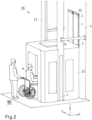
- Fig. 2 shows a further embodiment of a conveyor system 20 according to the invention and in addition to Fig. 1 how several users N, including a wheelchair user, enter an elevator car 23 on the street side in order to reach building G via the floor access module 1 shown.
- a shaft around the street-side access area is included in the Fig. 1 and 2 not shown.
- Fig. 3 shows an embodiment of a floor access module 1 according to the invention.
- the floor access module 1 can be at least partially pre-assembled.
- the floor access module 1 according to Fig. 3 a frame element 4 as a structural mechanical base body, whereby the frame element 4 is completely pre-assembled.
- the frame element 4 consists of four metal parts, namely an upper part 15, a sleeper part 16 as well as a left side part 17 and a right side part 18.
- the parts are only shown in Fig. 3 provided with the corresponding reference numerals.
- the parts 15, 16, 17, 18 of the frame element 4 can be connected to one another, e.g., via welded joints (not shown), before insertion into the facade opening F. This makes it easy to reduce the effort required to insert the floor access module 1 into the facade opening F, since any assembly steps no longer need to be carried out on site.
- the frame element 4 according to Fig. 3 an intermediate space 5.
- the intermediate space 5 corresponds to the internal volume of the frame element 4.
- the intermediate space 5 preferably has an internal height H of at least 200 cm along the vertical axis Z.
- an internal width B of the intermediate space 5 is preferably at least 90 cm along the transverse axis Y.
- An internal depth of the intermediate space 5 of at least 30 cm can be dimensioned along the longitudinal axis X.
- the internal depth of the intermediate space 5 preferably also corresponds to a spacing 6 between an end element 2 and a door element 3 of the floor access module 1.
- the external dimensions of the floor access module 1 can of course exceed the aforementioned internal dimensions, wherein the external dimensions of the floor access module 1 are limited by the available installation space in the facade opening F.
- the door element 3 shown is designed as a front door with a locking device 26 or door lock.
- the door element 3 delimits the space 5 of the Frame element 4 to an interior of building G (not shown) or secures building-side access to floor access module 1.
- Door element 3 is made of heat-insulating glass.
- Door element 3 is thus largely transparent—i.e., it has a transparent area 7 so that daylight from outside (e.g., from the environment 100) can enter building G.
- the Fig. 3 The insulating glass of the door element 3 shown also provides thermal insulation 8 of the transparent area 7 or of the entire floor access module 1.
- the thermal insulation 8 of the door element 3 is designed such that the thermal transmittance value is less than 1.3 W/m2K (watts per square meter and Kelvin).
- the value can be determined, for example, between a first side 81 of the floor access module 1 and a further side 82 of the floor access module 1.
- the first side 81 can, for example, be the side of the door element 3 facing the building, and the further side 82 can be the side of the door element 3 facing the intermediate space 5 (cf. Fig. 4 ).
- a storage device 11 and a retaining device 10 are arranged in the left side part 17 of the frame element 4.
- the storage device 11 is designed as a mailbox.
- the storage device 11 allows goods to be stored safely without the goods to be stored blocking the intermediate space 5 or obstructing access from the elevator system 21 to building G and vice versa.
- the retention device 10 is designed as a tensioning belt and can be used to secure goods in the intermediate space 5.
- goods e.g., beverage crates
- a drainage device 13 designed as a drain can be arranged in the threshold part 16 of the frame element 4.
- An opening of the drain can be divided into several slots by a grid.
- the drainage device 13 can be connected to a drainage system of the building, e.g., a gutter, via appropriate pipes, either above or below the plaster.
- the closing element 2 is designed as a two-part, glazed sliding door and delimits the intermediate space 5 of the frame element 4 to an elevator-side environment 100 or to the elevator system 21. Because both parts of the closing element 2 are glazed or designed as glass panes, the closing element 2 also has a transparent area 7.
- the closing element 2 is arranged on the frame element 4 via a guide rail 25.
- the sliding doors of the closing element 2 can be moved along the transverse axis Y via the guide rail 25. This is shown in Fig. 3 illustrated by arrows. When opened, the sliding doors of the closing element 2 are positioned in front of the facade of building G (cf. Fig. 4 ).
- the guide rail 25 can be heated by a heating element 12 designed as a heating resistor.
- the heating element 12 is arranged in front of the guide rail 25. This ensures trouble-free operation of the closing element 2, for example, even in winter or during frosty conditions (see. Fig. 3 ).
- the locking device 26 can be unlocked with a key, for example. This protects against unauthorized access to building G via the floor access module 1.
- the door element 3 can be operated alternatively or cumulatively, for example, via a handle set (see. Fig. 3 ).
- the end element 2 can only be actuated by a device 22 of the lift system 21 designed as a driver blade (cf. Fig. 4 ).
- the drive blade unlocks a means for locking the closure element 2 and sets the sliding doors of the closure element 2 in a sliding movement along a guide rail 25, so that the closure element 2 is moved from a locked state to an open state.
- a user N can then get from the elevator car 23 into the intermediate space 5.
- the user N - a provided that they have the appropriate access authorization, they can open the door element 3 and thus enter the building G. If the elevator car 23 starts moving again, the end element 2 is again actuated and locked by the device 22 of the elevator system 21 (cf. Fig. 4 ).
- Fig. 4 shows a top view - i.e. a perspective opposite the vertical axis Z - of another embodiment of a floor access module 1.
- the floor access module 1 is fitted into a facade opening F of a building G.
- an elevator car 23 of an elevator system 21 is arranged in front of the building G, which elevator car can be raised and lowered along the vertical axis Z.
- the floor access module 1 On the building side, the floor access module 1 has a door element 3 designed as a two-part hinged door. On the elevator side, the floor access module 1 has a closing element 2 designed as a two-part sliding door.
- the floor access module 1 is shown in a closed state in the right-hand part of the figure and in an open state in the left-hand part of the figure.
- the actuating device 22, designed as a driver blade has already actuated the end element 2 of the floor access module 1 in the left-hand part of the figure and, in the illustrated situation, is still engaged in a designated opening in the end element 2.
- the two parts of the figure are separated from each other by a dash-dot line.
- the door element 3 is pivoted open by 90 degrees.
- the pivoting movement required for actuation is shown by a dashed line.
- the door element 3 is completely recessed into the frame element 4.
- the frame element 4 can have a corresponding rebate to accommodate the door element 3 in the access opening on the building side. This can enable a flush finish between the door element 3 and the frame element 4 on the building side.
- This is particularly useful with regard to the arrangement of sealing lips for sealing the floor access module 1.
- the sealing lips can then be arranged, for example, on the edges of the door element 3 and/or, for example, in the rebate of the frame element 4.
- the closing element 2 is also shown in the left-hand part of the figure in an open state.
- the closing element 2 is arranged in front of the outer facade of the building G.
- a functional connection between the closing element 2 and a frame element 4 of the floor access module 1 is designed as a two-axis sliding connection 25, 27.
- the two-axis sliding connection 25, 27 has, according to Fig. 4 a hinge arm 27 guided in a biaxial guide rail 25.
- the hinge arm 27 is movably mounted in the guide rail 25.
- the end element 2 is displaced via the biaxial sliding connection 25, 27 both along the longitudinal axis X and along the transverse axis Y.
- a closed state is then achieved - as shown in the right-hand part of the figure - in which the end element 2 is flush with an outer side of the frame element 4.
- the gap between the elevator car 23 and the floor module 1 can be kept small.
- the guide rail 25 and the hinge arm 27 are not visible from the outside in a closed state and are arranged, for example, in an upper part 15 and/or threshold part 16 of the frame element 4. This ensures a uniform appearance of the exterior facade of the building G.
- the two-axis sliding connection 25, 27 can also ensure that the end element 2 is arranged in the closed state, e.g. in a fold of the frame element 4.
- the gap between the floor access module 1 or frame element 4 and the elevator car 23 can be closed by a gap-closing means 28 designed as a step.
- the step can be arranged on the frame element 4 and can be extended as needed—for example, when the elevator car 23 stops in front of the floor access module 1. It is also conceivable for the step to be part of the elevator car 23 and to be extended when the car stops.
Landscapes
- Engineering & Computer Science (AREA)
- Automation & Control Theory (AREA)
- Structural Engineering (AREA)
- Elevator Door Apparatuses (AREA)
- Special Wing (AREA)
Claims (10)
- Module d'accès à un étage (1) pour un système d'ascenseur (21), comprenant :- au moins un élément de châssis (4) pour l'agencement du module d'accès à un étage (1) dans une ouverture en façade (F) d'un bâtiment (G),- au moins un élément de fermeture côté ascenseur (2) pour une sécurisation de l'accès,- au moins un élément de porte côté bâtiment (3) pour la sécurisation de l'accès,dans lequel l'au moins un élément de fermeture (2) et l'au moins un élément de porte (3) sont reliés techniquement avec l'au moins un élément de châssis (4), dans lequel l'au moins un élément de fermeture (2) peut être actionné par un dispositif (22) du système d'ascenseur (21), dans lequel l'élément de châssis (4) présente au moins une ouverture d'accès côté ascenseur et au moins une ouverture d'accès côté bâtiment, dans lequel l'ouverture d'accès côté ascenseur est délimitée par l'élément de fermeture (2) et l'ouverture d'accès côté bâtiment est délimitée par l'élément de porte (3).
- Module d'accès à un étage (1) selon la revendication 1, caractérisé en ce que la liaison technique entre l'élément de fermeture (2) et l'élément de châssis (4) est conçue sous forme d'un assemblage coulissant à deux axes (25, 27).
- Module d'accès à un étage (1) selon l'une des revendications précédentes, caractérisé en ce que l'au moins un élément de châssis (4) abrite un espace intermédiaire (5), dans lequel l'au moins un élément de fermeture (2) et/ou l'au moins un élément de porte (3) délimitent l'espace intermédiaire (5), et/ou l'au moins un élément de fermeture (2) est à distance de l'au moins un élément de porte (3), dans lequel la distance (6) présente une valeur d'au moins 30 cm.
- Module d'accès à un étage (1) selon l'une des revendications précédentes, caractérisé en ce que l'au moins un élément de fermeture (2) et/ou l'au moins un élément de porte (3) présentent une zone (7) transparente, dans lequel un indice de transmission de la zone (7) transparente présente une valeur d'au moins 0,7.
- Module d'accès à un étage (1) selon l'une des revendications précédentes, caractérisé en ce que le module d'accès à un étage (1) présente au moins une isolation thermique (8), dans lequel un coefficient de transmission thermique entre deux côtés (81, 82) du module d'accès à un étage (1) présente une valeur inférieure à 2 W/qmK (Watt par mètre carré et degré Kelvin) du fait de l'isolation thermique (8).
- Module d'accès à un étage (1) selon l'une des revendications précédentes, caractérisé en ce que l'au moins un élément de fermeture (2) et/ou l'au moins un élément de porte (3) présentent des moyens de verrouillage.
- Module d'accès à un étage (1) selon l'une des revendications précédentes, caractérisé en ce que l'au moins un élément de châssis (4) présente au moins un dispositif de dépose (11) pour l'admission de marchandises, et/ou au moins un dispositif retenue (10) pour la sécurisation de marchandises, et/ou l'au moins un élément de châssis (4) présente des moyens (13) pour l'évacuation de l'eau.
- Module d'accès à un étage (1) selon l'une des revendications précédentes, caractérisé en ce que l'au moins un élément de châssis (4), et/ou l'élément de fermeture (2), et/ou l'élément de porte (3) présentent des systèmes de chauffage (12) pour la protection contre le gel.
- Système de transport (20) pour transporter des personnes et/ou des marchandises dans un bâtiment (G), comprenant :- au moins un module d'accès à un étage (1) selon l'une des revendications 1 à 8,- au moins un système d'ascenseur (21) pour transporter des personnes et/ou des marchandises,dans lequel le système d'ascenseur (21) présente un dispositif d'actionnement (22) de l'au moins un élément de fermeture (2) du module d'accès à un étage (1).
- Système de transport (20) selon la revendication 9, caractérisé en ce que le système de transport (20) présente un dispositif d'identification d'un utilisateur (N) ainsi qu'un dispositif de commande pour commander une sécurisation de l'accès, dans lequel le dispositif de commande est conçu pour l'exécution d'au moins une des étapes suivantes :- identification d'un utilisateur (N), où une autorisation d'accès est déterminée en fonction de l'utilisateur (N) identifié,- actionnement de l'au moins un élément de fermeture (2) en fonction de l'autorisation d'accès déterminée.
Applications Claiming Priority (1)
| Application Number | Priority Date | Filing Date | Title |
|---|---|---|---|
| DE102021004401.0A DE102021004401A1 (de) | 2021-08-20 | 2021-08-20 | Schachtabschlusstürkombination an einer Hausfassade |
Publications (3)
| Publication Number | Publication Date |
|---|---|
| EP4137432A1 EP4137432A1 (fr) | 2023-02-22 |
| EP4137432B1 true EP4137432B1 (fr) | 2025-04-02 |
| EP4137432C0 EP4137432C0 (fr) | 2025-04-02 |
Family
ID=83398226
Family Applications (1)
| Application Number | Title | Priority Date | Filing Date |
|---|---|---|---|
| EP22191283.5A Active EP4137432B1 (fr) | 2021-08-20 | 2022-08-19 | Module d'accès à étages pour une installation d'ascenseur et système de transport pour le transport de personnes et/ou de marchandises |
Country Status (2)
| Country | Link |
|---|---|
| EP (1) | EP4137432B1 (fr) |
| DE (1) | DE102021004401A1 (fr) |
Family Cites Families (4)
| Publication number | Priority date | Publication date | Assignee | Title |
|---|---|---|---|---|
| NL2002869C2 (nl) * | 2009-05-11 | 2010-11-18 | Reco Holding B V | Modulaire lift, werkwijze voor de vervaardiging en werkwijze voor de installatie hiervan. |
| CN209193489U (zh) * | 2018-09-27 | 2019-08-02 | 天津天玺建筑设计有限公司 | 一种适用于无电梯楼房的载人升降机 |
| CN111608416A (zh) | 2020-05-11 | 2020-09-01 | 北京筑福国际抗震技术有限责任公司 | 一种既有多层住宅单元门外侧增设电梯布置及其施工方法 |
| CN111824900B (zh) | 2020-07-16 | 2022-04-08 | 张涛 | 一种物流入户系统 |
-
2021
- 2021-08-20 DE DE102021004401.0A patent/DE102021004401A1/de not_active Withdrawn
-
2022
- 2022-08-19 EP EP22191283.5A patent/EP4137432B1/fr active Active
Also Published As
| Publication number | Publication date |
|---|---|
| EP4137432A1 (fr) | 2023-02-22 |
| DE102021004401A1 (de) | 2023-02-23 |
| EP4137432C0 (fr) | 2025-04-02 |
Similar Documents
| Publication | Publication Date | Title |
|---|---|---|
| EP3755186B1 (fr) | Élément de fenêtre, de porte, de toiture inclinée ou de façade, comprenant un dispositif pour l'envoi ou la réception d'une lettre ou d'un colis par un aéronef sans pilote | |
| EP3589812B1 (fr) | Fenêtre coulissante verticale pour un bâtiment | |
| DE102007059388B4 (de) | Modifizierte Traufe für Wintergärten mit integrierten Elementen zum Licht- und Sichtschutz und/oder zu Beleuchtungszwecken | |
| EP3214250B1 (fr) | Fenêtre coulissante verticale pour un bâtiment | |
| EP2435639B1 (fr) | Système de paroi extérieure coulissante et son procédé de montage dans un bâtiment existant | |
| EP4137432B1 (fr) | Module d'accès à étages pour une installation d'ascenseur et système de transport pour le transport de personnes et/ou de marchandises | |
| EP0692686B1 (fr) | Façade à double paroi | |
| WO2020011338A1 (fr) | Couverture de bâtiment comportant un élément en verre multifonctionnel | |
| EP0256441B1 (fr) | Elément de construction vitré | |
| DE19840418C2 (de) | Sonnenschutzvorrichtung | |
| DE19708262A1 (de) | Einsetzbares und verriegelbares Fenster- oder Tür-Element | |
| EP2204525B1 (fr) | Porte coulissante et tournante et applications anti-incendie | |
| DE10307311B4 (de) | Fenster oder Türe | |
| DE10028433B4 (de) | Photovoltaischer solarer Fensterladen mit hexagonalen Solarzellen | |
| EP2243917A2 (fr) | Système et module d'isolation | |
| EP0231423B1 (fr) | Elément de construction ou de paroi transparente, en particulier fenêtre | |
| EP0750707A1 (fr) | Lucarne | |
| DE19914845A1 (de) | Dachfenster | |
| AT501601B1 (de) | Zarge mit an dieser angelenktem/n flügel/n | |
| DE8633840U1 (de) | Vorgefertigte Fenster- und Rolladenvorrichtung für Häuser u. dgl. | |
| EP3118408B1 (fr) | Systeme de volet roulant | |
| DE102011116075A1 (de) | Schutztür für Deckenöffnungen | |
| DE3308211A1 (de) | Vorrichtung zum abdecken eines fensters oder dgl. | |
| DE8707653U1 (de) | Dachgartenwohnraumfenster | |
| DE3509772A1 (de) | Lichtdurchlaessiges wandelement, insbesondere fenster |
Legal Events
| Date | Code | Title | Description |
|---|---|---|---|
| PUAI | Public reference made under article 153(3) epc to a published international application that has entered the european phase |
Free format text: ORIGINAL CODE: 0009012 |
|
| STAA | Information on the status of an ep patent application or granted ep patent |
Free format text: STATUS: THE APPLICATION HAS BEEN PUBLISHED |
|
| AK | Designated contracting states |
Kind code of ref document: A1 Designated state(s): AL AT BE BG CH CY CZ DE DK EE ES FI FR GB GR HR HU IE IS IT LI LT LU LV MC MK MT NL NO PL PT RO RS SE SI SK SM TR |
|
| STAA | Information on the status of an ep patent application or granted ep patent |
Free format text: STATUS: REQUEST FOR EXAMINATION WAS MADE |
|
| 17P | Request for examination filed |
Effective date: 20230303 |
|
| RBV | Designated contracting states (corrected) |
Designated state(s): AL AT BE BG CH CY CZ DE DK EE ES FI FR GB GR HR HU IE IS IT LI LT LU LV MC MK MT NL NO PL PT RO RS SE SI SK SM TR |
|
| STAA | Information on the status of an ep patent application or granted ep patent |
Free format text: STATUS: EXAMINATION IS IN PROGRESS |
|
| 17Q | First examination report despatched |
Effective date: 20240305 |
|
| GRAP | Despatch of communication of intention to grant a patent |
Free format text: ORIGINAL CODE: EPIDOSNIGR1 |
|
| STAA | Information on the status of an ep patent application or granted ep patent |
Free format text: STATUS: GRANT OF PATENT IS INTENDED |
|
| INTG | Intention to grant announced |
Effective date: 20241030 |
|
| GRAS | Grant fee paid |
Free format text: ORIGINAL CODE: EPIDOSNIGR3 |
|
| GRAA | (expected) grant |
Free format text: ORIGINAL CODE: 0009210 |
|
| STAA | Information on the status of an ep patent application or granted ep patent |
Free format text: STATUS: THE PATENT HAS BEEN GRANTED |
|
| AK | Designated contracting states |
Kind code of ref document: B1 Designated state(s): AL AT BE BG CH CY CZ DE DK EE ES FI FR GB GR HR HU IE IS IT LI LT LU LV MC MK MT NL NO PL PT RO RS SE SI SK SM TR |
|
| REG | Reference to a national code |
Ref country code: GB Ref legal event code: FG4D Free format text: NOT ENGLISH |
|
| REG | Reference to a national code |
Ref country code: CH Ref legal event code: EP |
|
| REG | Reference to a national code |
Ref country code: IE Ref legal event code: FG4D Free format text: LANGUAGE OF EP DOCUMENT: GERMAN |
|
| REG | Reference to a national code |
Ref country code: DE Ref legal event code: R096 Ref document number: 502022003402 Country of ref document: DE |
|
| U01 | Request for unitary effect filed |
Effective date: 20250423 |
|
| U07 | Unitary effect registered |
Designated state(s): AT BE BG DE DK EE FI FR IT LT LU LV MT NL PT RO SE SI Effective date: 20250429 |
|
| U20 | Renewal fee for the european patent with unitary effect paid |
Year of fee payment: 4 Effective date: 20250827 |
|
| PG25 | Lapsed in a contracting state [announced via postgrant information from national office to epo] |
Ref country code: ES Free format text: LAPSE BECAUSE OF FAILURE TO SUBMIT A TRANSLATION OF THE DESCRIPTION OR TO PAY THE FEE WITHIN THE PRESCRIBED TIME-LIMIT Effective date: 20250402 |
|
| PG25 | Lapsed in a contracting state [announced via postgrant information from national office to epo] |
Ref country code: NO Free format text: LAPSE BECAUSE OF FAILURE TO SUBMIT A TRANSLATION OF THE DESCRIPTION OR TO PAY THE FEE WITHIN THE PRESCRIBED TIME-LIMIT Effective date: 20250702 Ref country code: GR Free format text: LAPSE BECAUSE OF FAILURE TO SUBMIT A TRANSLATION OF THE DESCRIPTION OR TO PAY THE FEE WITHIN THE PRESCRIBED TIME-LIMIT Effective date: 20250703 |
|
| PG25 | Lapsed in a contracting state [announced via postgrant information from national office to epo] |
Ref country code: PL Free format text: LAPSE BECAUSE OF FAILURE TO SUBMIT A TRANSLATION OF THE DESCRIPTION OR TO PAY THE FEE WITHIN THE PRESCRIBED TIME-LIMIT Effective date: 20250402 |
|
| PG25 | Lapsed in a contracting state [announced via postgrant information from national office to epo] |
Ref country code: HR Free format text: LAPSE BECAUSE OF FAILURE TO SUBMIT A TRANSLATION OF THE DESCRIPTION OR TO PAY THE FEE WITHIN THE PRESCRIBED TIME-LIMIT Effective date: 20250402 |
|
| PG25 | Lapsed in a contracting state [announced via postgrant information from national office to epo] |
Ref country code: RS Free format text: LAPSE BECAUSE OF FAILURE TO SUBMIT A TRANSLATION OF THE DESCRIPTION OR TO PAY THE FEE WITHIN THE PRESCRIBED TIME-LIMIT Effective date: 20250702 |
|
| PG25 | Lapsed in a contracting state [announced via postgrant information from national office to epo] |
Ref country code: IS Free format text: LAPSE BECAUSE OF FAILURE TO SUBMIT A TRANSLATION OF THE DESCRIPTION OR TO PAY THE FEE WITHIN THE PRESCRIBED TIME-LIMIT Effective date: 20250802 |
|
| PG25 | Lapsed in a contracting state [announced via postgrant information from national office to epo] |
Ref country code: SM Free format text: LAPSE BECAUSE OF FAILURE TO SUBMIT A TRANSLATION OF THE DESCRIPTION OR TO PAY THE FEE WITHIN THE PRESCRIBED TIME-LIMIT Effective date: 20250402 |
|
| PG25 | Lapsed in a contracting state [announced via postgrant information from national office to epo] |
Ref country code: CZ Free format text: LAPSE BECAUSE OF FAILURE TO SUBMIT A TRANSLATION OF THE DESCRIPTION OR TO PAY THE FEE WITHIN THE PRESCRIBED TIME-LIMIT Effective date: 20250402 |
|
| PG25 | Lapsed in a contracting state [announced via postgrant information from national office to epo] |
Ref country code: SK Free format text: LAPSE BECAUSE OF FAILURE TO SUBMIT A TRANSLATION OF THE DESCRIPTION OR TO PAY THE FEE WITHIN THE PRESCRIBED TIME-LIMIT Effective date: 20250402 |
|
| PLBE | No opposition filed within time limit |
Free format text: ORIGINAL CODE: 0009261 |
|
| STAA | Information on the status of an ep patent application or granted ep patent |
Free format text: STATUS: NO OPPOSITION FILED WITHIN TIME LIMIT |
|
| REG | Reference to a national code |
Ref country code: CH Ref legal event code: L10 Free format text: ST27 STATUS EVENT CODE: U-0-0-L10-L00 (AS PROVIDED BY THE NATIONAL OFFICE) Effective date: 20260211 |
|
| 26N | No opposition filed |
Effective date: 20260105 |
|
| REG | Reference to a national code |
Ref country code: CH Ref legal event code: H13 Free format text: ST27 STATUS EVENT CODE: U-0-0-H10-H13 (AS PROVIDED BY THE NATIONAL OFFICE) Effective date: 20260324 |
|
| PG25 | Lapsed in a contracting state [announced via postgrant information from national office to epo] |
Ref country code: MC Free format text: LAPSE BECAUSE OF FAILURE TO SUBMIT A TRANSLATION OF THE DESCRIPTION OR TO PAY THE FEE WITHIN THE PRESCRIBED TIME-LIMIT Effective date: 20250402 |
|
| PG25 | Lapsed in a contracting state [announced via postgrant information from national office to epo] |
Ref country code: CH Free format text: LAPSE BECAUSE OF NON-PAYMENT OF DUE FEES Effective date: 20250831 |