EP4137699A1 - Appareil à vide et procédé de fonctionnement d'un tel appareil à vide - Google Patents
Appareil à vide et procédé de fonctionnement d'un tel appareil à vide Download PDFInfo
- Publication number
- EP4137699A1 EP4137699A1 EP22213776.2A EP22213776A EP4137699A1 EP 4137699 A1 EP4137699 A1 EP 4137699A1 EP 22213776 A EP22213776 A EP 22213776A EP 4137699 A1 EP4137699 A1 EP 4137699A1
- Authority
- EP
- European Patent Office
- Prior art keywords
- vacuum device
- wear
- vacuum
- operating
- pump
- Prior art date
- Legal status (The legal status is an assumption and is not a legal conclusion. Google has not performed a legal analysis and makes no representation as to the accuracy of the status listed.)
- Granted
Links
Images




Classifications
-
- F—MECHANICAL ENGINEERING; LIGHTING; HEATING; WEAPONS; BLASTING
- F04—POSITIVE - DISPLACEMENT MACHINES FOR LIQUIDS; PUMPS FOR LIQUIDS OR ELASTIC FLUIDS
- F04D—NON-POSITIVE-DISPLACEMENT PUMPS
- F04D19/00—Axial-flow pumps
- F04D19/02—Multi-stage pumps
- F04D19/04—Multi-stage pumps specially adapted to the production of a high vacuum, e.g. molecular pumps
-
- F—MECHANICAL ENGINEERING; LIGHTING; HEATING; WEAPONS; BLASTING
- F04—POSITIVE - DISPLACEMENT MACHINES FOR LIQUIDS; PUMPS FOR LIQUIDS OR ELASTIC FLUIDS
- F04D—NON-POSITIVE-DISPLACEMENT PUMPS
- F04D27/00—Control, e.g. regulation, of pumps, pumping installations or pumping systems specially adapted for elastic fluids
- F04D27/001—Testing thereof; Determination or simulation of flow characteristics; Stall or surge detection, e.g. condition monitoring
-
- F—MECHANICAL ENGINEERING; LIGHTING; HEATING; WEAPONS; BLASTING
- F04—POSITIVE - DISPLACEMENT MACHINES FOR LIQUIDS; PUMPS FOR LIQUIDS OR ELASTIC FLUIDS
- F04D—NON-POSITIVE-DISPLACEMENT PUMPS
- F04D27/00—Control, e.g. regulation, of pumps, pumping installations or pumping systems specially adapted for elastic fluids
- F04D27/02—Surge control
- F04D27/0292—Stop safety or alarm devices, e.g. stop-and-go control; Disposition of check-valves
Definitions
- the invention relates to a vacuum device, for example a vacuum pump or a measuring tube, and methods for operating such a vacuum device.
- a turbomolecular vacuum pump can, for example, have roller bearings and/or backup bearings for its rotor, in which a certain amount of wear can ultimately lead to failure of the vacuum pump. Wear and tear can also lead to previous damage to certain components of the vacuum device, which can be aggravated by uncontrolled further operation of the vacuum device and can lead to a complete failure of the vacuum device. This can occur, for example, if a vacuum pump continues to be operated at nominal conditions with regard to temperature, power and speed despite some previous damage to a bearing. For example, if pre-damage to the bearing is not detected, operating at rated conditions reduces the time to pump failure.
- maintenance recommendations or similar specifications are often provided which, for example, define a check of the vacuum device after a specified operating time or under certain other conditions.
- a failure of the vacuum device can occur, for example due to the operating mode of a respective vacuum pump, before the end of such a maintenance period if the wear of certain components of the vacuum device is not detected.
- the intended operating time up to maintenance can be selected too conservatively, so that maintenance is carried out unnecessarily. This leads to unnecessary costs for the operation of the vacuum device.
- the vacuum device which is in particular a vacuum pump, includes a wear detection device and a protective device.
- the wear detection device is designed to record a set of operating parameters of the vacuum device and to determine at least one wear indicator for the vacuum device based on the recorded operating parameters, which indicates the wear of at least one component of the vacuum device.
- the protective device is designed to carry out a measure to reduce the wear of the vacuum device or the wear of one or more components of the vacuum device when the at least one wear indicator assumes a predetermined state.
- the set of operating variables of the vacuum device includes at least one operating variable, such as the number of operating hours of the vacuum device.
- the wear detection device can be designed to record the previous operating hours of the vacuum device.
- the wear detection device can additionally or alternatively be designed to detect specific, predetermined disruption events and to assign a detected disruption event to a specific wear. In both cases, i.e. based on the total number of operating hours and/or based on the detected fault events of the vacuum device, the wear detection device can assign a specific numerical value as a wear indicator to these recorded operating variables.
- the wear detection device can detect certain operating parameters of the vacuum device, such as the temperature and the speed of a vacuum pump.
- the respective value of the operating parameter can be recorded over a predetermined period of time in order to relate the wear indicator to the values of the operating parameter recorded in this way.
- the values of the operating parameter recorded over the predetermined period of time can, for example, be summed, integrated or offset against one another in some other way in order to obtain an average value for the operating parameter, based on which the wear indicator can be determined.
- the wear detection device can detect the state of a specific operating resource of the vacuum device and assign this state to the wear indicator.
- Such a condition of the equipment can include, for example, the temperature of a coolant in the vacuum device and/or the quality of certain lubricants.
- the wear indicator can thus either assume a specific numerical value, which is derived, for example, based on the operating hours, based on fault events and/or based on a detected operating parameter of the vacuum device.
- the predetermined state of the wear indicator which triggers the measure for reducing wear in the vacuum device by means of the protective device, can include the numerical value of the wear indicator exceeding a predetermined threshold value.
- the wear indicator can be assigned directly to a specific condition of an item of equipment in the vacuum device, so that the condition of the item of equipment, e.g. exceeding a specific temperature of the coolant in the vacuum device, triggers the measure to reduce wear directly.
- the measure for reducing the wear of the vacuum device can include that certain operating parameters of the vacuum device are adjusted in such a way that the wear of the at least one component of the vacuum device is reduced.
- a maximum possible speed can be reduced in order to be able to continue to operate the vacuum pump without, for example, damage occurring to its roller bearings or backup bearings.
- the vacuum device according to the invention is thus characterized in that not only the wear of one of the components of the vacuum device is detected, for example by counting operating hours, but that a suitable measure to reduce wear is also triggered using the wear indicator.
- a suitable measure to reduce wear is also triggered using the wear indicator.
- the set of operating variables can include an operating time of the vacuum device, and the at least one wear indicator can include a numerical value that is derived from the operating time of the vacuum device.
- the operating time can be recorded from a previous maintenance of the vacuum device if, for example, parts or components of the vacuum device that are subject to wear are repaired or replaced during this maintenance. Alternatively, the entire operating time of the vacuum device can be recorded. Specifically, the operating hours of the vacuum device can be counted so that the numerical value of the operating hours represents the wear indicator. The number of operating hours can be compared to a predetermined threshold value that is associated with a certain probability that the wear of a component of the vacuum device can lead to a malfunction or even a failure of the vacuum device within a relatively short period of time.
- Such a threshold may be configurable, meaning that the threshold may be adaptable to the particular type of vacuum device and to the environment in which the vacuum device is used. Furthermore, the detection of the operating time of the vacuum device can be associated with little effort since, for example, the operating hours of many vacuum pumps are counted anyway.
- the set of operating variables can include operating parameters of the vacuum device.
- the wear detection device can be designed to determine the wear indicator by detecting values of the operating parameter over a predetermined period of time and relating them to the wear indicator.
- the operating parameter can include, for example, a temperature in a predetermined range of the vacuum device and/or a vibration of the vacuum device. For example, a period of time can be recorded during which the temperature of the vacuum device is above a predetermined limit value. Additionally or alternatively, the intensity, frequencies and/or the amplitude of vibrations of the vacuum device can be recorded over a predetermined period of time.
- the amplitude of the vibrations cumulatively exceeds a predetermined limit value for a certain period of time and/or predetermined characteristics are recognizable in the frequencies of the vibrations, this can be associated with increased wear of one or more components of the vacuum device.
- the measurement of the vibrations of the vacuum device can thus be assigned to a corresponding wear indicator.
- the vacuum device is a vacuum pump
- the pressure, the speed, one or more speed/pressure cycle or multiple speed/pressure cycles and/or a gas flow in the vacuum pump can also be detected as part of the set of operating variables of the vacuum pump. From the detection of these operating variables over a predetermined period of time, it can in turn be determined whether increased wear has occurred in a specific area or on a specific component of the vacuum pump.
- the set of operating variables can include a state of at least one piece of equipment of the vacuum device.
- the wear detection device can be designed to determine the wear indicator based on the state of the at least one piece of equipment.
- the condition of the equipment can in particular be the temperature of a coolant and/or the quality of a lubricant for at least one component of the Vacuum device include.
- the wear of a component of the vacuum device can thus be detected indirectly based on the interaction of the component with the equipment.
- increased wear of a specific component of the vacuum device can be associated with a change in the condition of the at least one piece of equipment, so that this change in the condition of the item of equipment can be used as a wear indicator.
- the change in the temperature of the coolant and/or the reduction in the quality of the lubricant which can be detected, for example, by clouding of the lubricating oil of a vacuum pump, are indicators of the wear of that component of the vacuum device for which the coolant or lubricant is intended .
- the set of operating variables of the vacuum device can only comprise one operating variable, such as the operating hours of the vacuum device.
- the set of operating variables can advantageously include a number of operating variables that are detected simultaneously.
- the set of operating variables may include the operating time of the vacuum device, one or more operating parameters such as the temperature and/or vibration of the vacuum device, and the condition of a coolant or lubricant.
- a respective wear indicator can be assigned to each of these operating variables.
- the protective device can be designed to carry out one or more measures to reduce the wear of the vacuum device as soon as at least one of the several wear indicators assumes a predetermined state, ie for example exceeds a certain threshold value. If the set of operating variables in such an embodiment includes several operating variables, it can be ensured that the measure to reduce the Wear of the vacuum device is carried out in good time and that on the other hand, however, maintenance of the vacuum device is not carried out unnecessarily too early.
- the protective device can be designed to carry out the measure for reducing the wear and tear of the vacuum device in such a way that the power consumption of the vacuum device is limited.
- the power consumption of the vacuum device for example, its temperature, its vibrations and/or its mechanical load can be limited in such a way that additional wear of one or more components of the vacuum device is ruled out or at least reduced. If the vacuum device is a vacuum pump, limiting the power consumption may reduce the maximum possible speed of the vacuum pump.
- a process performed in a vacuum facility in which the vacuum device is installed may be limited by the reduced power consumption of the vacuum device. Such a limitation can be tolerable, so that the process can still be executed despite the reduced power consumption.
- the available service life of the vacuum device can be extended, so that the process can continue to be performed despite the reduction in power consumption.
- reducing the power consumption of the vacuum device just by increasing the available service life of the vacuum device, allows the process to continue to be carried out and completed, which may not be guaranteed without the reduction in the power consumption of the vacuum device due to the additional wear and tear of the vacuum device.
- the measure for reducing the wear of the vacuum device can also be implemented in such a way that the use of operating reserves is restricted, which are not taken into account during normal operation of the vacuum device and usually only play a role in transitions between operating states of the vacuum device. If, for example, a vacuum pump is to change from a previous operating point to a new operating point with regard to the pressure in a recipient that is connected to the vacuum pump, a reduction in the maximum power consumption of the vacuum pump can result in the vacuum pump being switched off for the transition phase between the two operating points requires a longer period of time, i.e. compared to the period that would be required without the limitation of the maximum power consumption.
- a corresponding process that is carried out in the vacuum system with the recipient may not be affected by the limitation of the maximum power consumption of the vacuum pump, or the limitation of the maximum power consumption of the vacuum pump only leads to an extension of individual process steps. This can be tolerable as long as the process itself is fully feasible.
- the protective device can also be designed to carry out the measure for reducing the wear of the vacuum device in such a way that at least one limit value for issuing a warning and/or an error message for at least one of the operating variables is reduced.
- the wear indicator can indicate that the vacuum device is less resilient due to the wear of at least one component and should be switched off, for example, when the reduced limit value of a specific operating variable is reached.
- the protective device can additionally or alternatively be designed to carry out the measure for reducing the wear of the vacuum device by adapting a state of at least one piece of equipment of the vacuum device.
- a quantity of an available resource for example a coolant and/or lubricant, can be increased or decreased depending on the temperature of the vacuum device in order to counteract additional wear of a component of the vacuum device.
- a further aspect of the invention relates to a method for operating a vacuum device, in particular a vacuum pump.
- a set of operating variables of the vacuum device is detected using a wear detection device, and at least one wear indicator for the vacuum device is determined based on the detected operating variables, which indicates the wear of at least one component of the vacuum device. If the at least one wear indicator assumes a predetermined state, a measure to reduce the wear of the vacuum device is carried out by means of a protective device.
- the predetermined condition may include the wear indicator having a numerical value that is greater than a predetermined threshold value, or the wear indicator directly reflecting a condition of one or more operating variables.
- the vacuum device described above is therefore intended to carry out the steps of the method by means of the wear detection device and the protective device.
- the above statements on the vacuum device according to the invention therefore also apply to the Method according to the invention, in particular with regard to the disclosure, the advantages and the preferred embodiments.
- the set of operating variables can include an operating time of the vacuum device, and a numerical value of the at least one wear indicator can be derived from the operating time of the vacuum device. Determining the operating time of the vacuum device can, for example, include counting its operating hours, for example in a vacuum pump.
- the set of operating variables can alternatively or additionally include at least one operating parameter of the vacuum device.
- the wear indicator can be determined by detecting values of the operating parameter over a predetermined period of time and relating them to the wear indicator.
- the operating parameter can include, for example, the temperature of the vacuum device and/or an amplitude or frequency characteristic of vibrations of the vacuum device, which can be cumulatively detected.
- the vacuum device is a vacuum pump
- the operating parameter may include a pressure, a speed of a rotor of the vacuum pump, one or more speed/pressure cycles, and/or a gas flow in the vacuum pump.
- the set of operating variables can include a state of at least one piece of equipment of the vacuum device.
- the wear indicator can be determined based on the state of the at least one piece of equipment.
- the condition of the equipment can include, for example, the temperature of a coolant for the vacuum device and/or the quality of a lubricant for at least one component of the vacuum device.
- the measure for reducing the wear of the vacuum device can also be carried out by means of the protective device in such a way that the power consumption of the vacuum device is limited.
- the measure to reduce the Wear of the vacuum device can alternatively or additionally be carried out in such a way that at least one limit value for outputting maintenance and/or an error message for at least one of the operating variables is reduced.
- the measure to reduce the wear of the vacuum device can be carried out by a state of at least one piece of equipment of the vacuum device being adjusted. Adjusting the state of the consumable may include increasing or decreasing an available amount of the consumable for a component of the vacuum device to thereby reduce wear on the component.
- the turbomolecular pump 111 shown comprises a pump inlet 115 surrounded by an inlet flange 113, to which a recipient, not shown, can be connected in a manner known per se.
- the gas from the recipient can be sucked out of the recipient via the pump inlet 115 and conveyed through the pump to a pump outlet 117 to which a backing pump, such as a rotary vane pump, can be connected.
- the inlet flange 113 forms when the vacuum pump is aligned according to FIG 1 the upper end of the housing 119 of the vacuum pump 111.
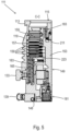
- the housing 119 comprises a lower part 121 on which an electronics housing 123 is arranged laterally. Electrical and/or electronic components of the vacuum pump 111 are accommodated in the electronics housing 123, for example for operating an electric motor 125 arranged in the vacuum pump (cf. also 3 ). Several connections 127 for accessories are provided on the electronics housing 123 .
- a data interface 129 for example according to the RS485 standard, and a power supply connection 131 are arranged on the electronics housing 123.
- turbomolecular pumps that do not have such an attached electronics housing, but are connected to external drive electronics.
- a flood inlet 133 in particular in the form of a flood valve, is provided on the housing 119 of the turbomolecular pump 111, via which the vacuum pump 111 can be flooded.
- a sealing gas connection 135, which is also referred to as a flushing gas connection through which flushing gas to protect the electric motor 125 (see e.g 3 ) before the pumped gas in the motor compartment 137, in which the electric motor 125 is housed in the vacuum pump 111, can be admitted.
- Two coolant connections 139 are also arranged in the lower part 121, one of the coolant connections being provided as an inlet and the other coolant connection being provided as an outlet for coolant, which can be conducted into the vacuum pump for cooling purposes.
- Other existing turbomolecular vacuum pumps (not shown) operate solely on air cooling.
- the lower side 141 of the vacuum pump can serve as a standing surface, so that the vacuum pump 111 can be operated standing on the underside 141 .
- the vacuum pump 111 can also be fastened to a recipient via the inlet flange 113 and can thus be operated in a suspended manner, as it were.
- the vacuum pump 111 can be designed in such a way that it can also be operated when it is oriented in a different way than in FIG 1 is shown. It is also possible to realize embodiments of the vacuum pump in which the underside 141 cannot be arranged facing downwards but to the side or directed upwards. In principle, any angles are possible.
- various screws 143 are also arranged, by means of which components of the vacuum pump that are not further specified here are fastened to one another.
- a bearing cap 145 is attached to the underside 141 .
- fastening bores 147 are arranged on the underside 141, via which the pump 111 can be fastened, for example, to a support surface. This is with other existing turbomolecular vacuum pumps (Not shown), which are in particular larger than the pump shown here, is not possible.
- a coolant line 148 is shown, in which the coolant fed in and out via the coolant connections 139 can circulate.
- the vacuum pump comprises several process gas pump stages for conveying the process gas present at the pump inlet 115 to the pump outlet 117.
- a rotor 149 is arranged in the housing 119 and has a rotor shaft 153 which can be rotated about an axis of rotation 151 .
- the turbomolecular pump 111 comprises a plurality of turbomolecular pumping stages connected in series with one another in a pumping manner, with a plurality of radial rotor disks 155 fastened to the rotor shaft 153 and stator disks 157 arranged between the rotor disks 155 and fixed in the housing 119.
- a rotor disk 155 and an adjacent stator disk 157 each form a turbomolecular pump stage.
- the stator discs 157 are held at a desired axial distance from one another by spacer rings 159 .
- the vacuum pump also comprises Holweck pump stages which are arranged one inside the other in the radial direction and are connected in series with one another for pumping purposes.
- Other turbomolecular vacuum pumps (not shown) exist that do not have Holweck pumping stages.
- the rotor of the Holweck pump stages comprises a rotor hub 161 arranged on the rotor shaft 153 and two cylinder-jacket-shaped Holweck rotor sleeves 163, 165 fastened to the rotor hub 161 and carried by it, which are coaxial with the Axis of rotation 151 are oriented and nested in the radial direction. Also provided are two cylinder jacket-shaped Holweck stator sleeves 167, 169, which are also oriented coaxially with respect to the axis of rotation 151 and are nested in one another when viewed in the radial direction.
- the pumping-active surfaces of the Holweck pump stages are formed by the lateral surfaces, ie by the radial inner and/or outer surfaces, of the Holweck rotor sleeves 163, 165 and the Holweck stator sleeves 167, 169.
- the radial inner surface of the outer Holweck stator sleeve 167 lies opposite the radial outer surface of the outer Holweck rotor sleeve 163, forming a radial Holweck gap 171 and forming with it the first Holweck pump stage following the turbomolecular pumps.
- the radially inner surface of the outer Holweck rotor sleeve 163 faces the radially outer surface of the inner Holweck stator sleeve 169 to form a radial Holweck gap 173 and therewith forms a second Holweck pumping stage.
- the radially inner surface of the inner Holweck stator sleeve 169 faces the radially outer surface of the inner Holweck rotor sleeve 165 to form a radial Holweck gap 175 and therewith forms the third Holweck pumping stage.
- a radially running channel can be provided, via which the radially outer Holweck gap 171 is connected to the middle Holweck gap 173.
- a radially extending channel can be provided at the upper end of the inner Holweck stator sleeve 169, via which the middle Holweck gap 173 is connected to the radially inner Holweck gap 175.
- a connecting channel 179 to the outlet 117 can be provided at the lower end of the radially inner Holweck rotor sleeve 165 .
- the above-mentioned pumping-active surfaces of the Holweck stator sleeves 167, 169 each have a plurality of Holweck grooves running in a spiral shape around the axis of rotation 151 in the axial direction, while the opposite lateral surfaces of the Holweck rotor sleeves 163, 165 are smooth and the gas for operating the Advance vacuum pump 111 in the Holweck grooves.
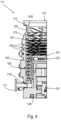
- a roller bearing 181 in the region of the pump outlet 117 and a permanent magnet bearing 183 in the region of the pump inlet 115 are provided for the rotatable mounting of the rotor shaft 153 .
- a conical spray nut 185 is provided on the rotor shaft 153 with an outer diameter that increases towards the roller bearing 181 .
- the injection nut 185 is in sliding contact with at least one stripper of an operating fluid store.
- an injection screw may be provided instead of an injection nut. Since different designs are thus possible, the term "spray tip" is also used in this context.
- the resource reservoir comprises a plurality of absorbent discs 187 stacked on top of one another, which are impregnated with a resource for the roller bearing 181, e.g. with a lubricant.
- the operating fluid is transferred by capillary action from the operating fluid reservoir via the scraper to the rotating spray nut 185 and, as a result of the centrifugal force, is conveyed along the spray nut 185 in the direction of the increasing outer diameter of the spray nut 185 to the roller bearing 181, where it eg fulfills a lubricating function.
- the roller bearing 181 and the operating fluid reservoir are surrounded by a trough-shaped insert 189 and the bearing cover 145 in the vacuum pump.
- the permanent magnet bearing 183 comprises a bearing half 191 on the rotor side and a bearing half 193 on the stator side, which each comprise a ring stack of a plurality of permanent magnetic rings 195, 197 stacked on top of one another in the axial direction.
- the ring magnets 195, 197 lie opposite one another, forming a radial bearing gap 199, the ring magnets 195 on the rotor side being arranged radially on the outside and the ring magnets 197 on the stator side being arranged radially on the inside.
- the magnetic field present in the bearing gap 199 produces magnetic repulsive forces between the ring magnets 195, 197, which cause the rotor shaft 153 to be supported radially.
- the ring magnets 195 on the rotor side are carried by a support section 201 of the rotor shaft 153, which radially surrounds the ring magnets 195 on the outside.
- the ring magnets 197 on the stator side are carried by a support section 203 on the stator side, which extends through the ring magnets 197 and is suspended on radial struts 205 of the housing 119 .
- the ring magnets 195 on the rotor side are fixed parallel to the axis of rotation 151 by a cover element 207 coupled to the carrier section 201 .
- the stator-side ring magnets 197 are fixed parallel to the axis of rotation 151 in one direction by a fastening ring 209 connected to the support section 203 and a fastening ring 211 connected to the support section 203 .
- a disc spring 213 can also be provided between the fastening ring 211 and the ring magnet 197 .
- An emergency or safety bearing 215 is provided within the magnetic bearing, which runs idle without contact during normal operation of the vacuum pump 111 and only engages in the event of an excessive radial deflection of the rotor 149 relative to the stator, in order to create a radial stop for the rotor 149 to form, so that a collision of the rotor-side structures is prevented with the stator-side structures.
- the backup bearing 215 is designed as an unlubricated roller bearing and forms a radial gap with the rotor 149 and/or the stator, which causes the backup bearing 215 to be disengaged during normal pumping operation.
- the radial deflection at which the backup bearing 215 engages is large enough dimensioned so that the safety bearing 215 does not engage during normal operation of the vacuum pump, and at the same time small enough so that a collision of the rotor-side structures with the stator-side structures is prevented under all circumstances.
- the vacuum pump 111 includes the electric motor 125 for rotating the rotor 149.
- the armature of the electric motor 125 is formed by the rotor 149, the rotor shaft 153 of which extends through the motor stator 217.
- a permanent magnet arrangement can be arranged radially on the outside or embedded on the section of the rotor shaft 153 that extends through the motor stator 217 .
- the motor stator 217 is fixed in the housing inside the motor room 137 provided for the electric motor 125 .
- a sealing gas which is also referred to as flushing gas and which can be air or nitrogen, for example, can get into the engine compartment 137 via the sealing gas connection 135 .
- the sealing gas can protect the electric motor 125 from process gas, e.g. from corrosive components of the process gas.
- the engine compartment 137 can also be evacuated via the pump outlet 117, i.e. the vacuum pressure produced by the backing pump connected to the pump outlet 117 prevails in the engine compartment 137 at least approximately.
- a labyrinth seal 223 can also be provided between the rotor hub 161 and a wall 221 delimiting the motor compartment 137, in particular in order to achieve better sealing of the motor compartment 217 in relation to the Holweck pump stages located radially outside.
- FIG. 6 shows a schematic block diagram of a vacuum device 600, which is, for example, the device shown in Figures 1 to 5 illustrated turbomolecular pump 111 is.
- the vacuum device 600 includes components 610 that are known to potentially wear out during operation of the vacuum device 600 .
- the components 610 include the roller bearing 181 (cf. Figures 3 to 5 ) and the emergency or catch camp 215 (cf. 3 ) and all the parts of the turbomolecular pump 111 described above that are movable during operation.
- the components 610 also include, on the one hand, the moving parts of the electric motor 125 (cf. 3 ) and on the other hand those electrical and electronic elements of the electric motor 125 which are exposed to a particular load during operation of the turbomolecular pump 111, for example an increased temperature and/or a high voltage and/or a high current intensity.
- Vacuum device 600 also includes a wear detection device 620, which is connected to components 610 of vacuum device 600, in order to record a set of operating variables of the vacuum device and, based on the recorded operating variables, to determine at least one wear indicator for vacuum device 600 that indicates the wear of at least one Component 610 of the vacuum device 600 indicates. If the vacuum device 600 is the turbomolecular pump 111, then the wear detection device 620 detects the operating time of the vacuum device 600 or the turbomolecular pump 111 through a communicative connection with the electric motor 125 as the first element of the set of operating variables. Based on the operating time of the vacuum device 600, the wear detection device guides 620 a numerical value that is used as a wear indicator of the vacuum device 600.
- the wear detection device 620 also detects operating parameters of the vacuum device 600, which in the case of the turbomolecular pump 111 include its temperature, the pressure on its high-vacuum side, the speed of the rotor 149, one or more speed/pressure cycles and vibrations of the turbomolecular pump 111, the latter being controlled by a not shown vibration sensor are measured. Using these detected operating parameters of vacuum device 600 or turbomolecular pump 111, wear detection device 620 in turn determines one or more wear indicators that are specific to one or more of the above-mentioned operating parameters and are assigned to them.
- Values of the respective operating variable are recorded over a predetermined period of time and compared with a respective threshold value in order to determine whether one or more of the components 610 of the vacuum device 600 are exposed to increased wear.
- the wear indicator is thus related to the recorded values of the operating parameter.
- the values of the operating parameter recorded over the predetermined period of time are, for example, summed, integrated or offset against one another in some other way in order to thereby obtain a mean value for the operating parameter, on the basis of which the wear indicator is determined.
- the wear detection device 620 also detects a state of at least one piece of equipment of the vacuum device 600, for example in the case of the turbomolecular pump 111 the quality of a lubricant for those components of the turbomolecular pump 111 that require lubrication.
- the quality of the lubricant can be detected, for example, by monitoring one or more physical and/or chemical properties of the lubricant, e.g., the presence of a certain substance in the lubricant, its viscosity and/or its optical properties.
- the vacuum device 600 also includes a protective device 630 which is intended to be a measure for reducing the wear and tear of the vacuum device 600 to be executed when the at least one wear indicator assumes a predetermined state.
- the wear detection device 620 communicates with the protective device 630 and transmits the respective wear indicators of the various operating variables of the vacuum device 600 to the protective device 630.
- the state of the respective wear indicator, which the protective device 630 uses to trigger the measure to reduce the wear of the vacuum device 600 is given in the case of the operating time and the operating parameters in that their values exceed a respective predetermined threshold value.
- a predefined state of the operating resources is assigned to that state of the wear indicator that triggers the measure to reduce the wear of the vacuum device 600 .
- this measure includes limiting the power consumption of the turbomolecular pump 111.
- the maximum achievable speed of the rotor 149 of the turbomolecular pump 111 is also limited. This limitation of the maximum speed of the rotor 149 reduces the wear on the roller bearing 181 (cf. Figures 3 to 5 ) and also the emergency or catch camp 215 (cf. 3 ) that would otherwise occur if the turbomolecular pump 111 continued to operate at its rated speed.
- FIG. 7 shows a schematic flowchart of a method 700 for operating the vacuum device 600, ie in particular the turbomolecular pump 111.
- a set of operating variables of the vacuum device 600 is detected by means of the wear detection device 620, which are each assigned to the various components 610 of the vacuum device 600.
- the operating variables include the number of operating hours of the turbomolecular pump 111, the temperature, the speed of the rotor 149 and the pressure in the turbomolecular pump 111.
- a respective wear indicator for the vacuum device 600 is determined by means of the wear detection device 620 based on the detected operating variables, which indicates the wear of one or more components 610 of the vacuum device 600.
- a measure to reduce the wear of the vacuum device 600 is carried out at 740 by means of the protective device.
- the power consumption of the turbomolecular pump 111 is limited in order to thereby limit the maximum speed of the rotor 149 and the roller bearing 181 (cf. Figures 3 to 5 ) and the emergency or catch camp 215 (cf. 3 ) to protect.
Landscapes
- Engineering & Computer Science (AREA)
- Mechanical Engineering (AREA)
- General Engineering & Computer Science (AREA)
- Non-Positive Displacement Air Blowers (AREA)
Priority Applications (2)
| Application Number | Priority Date | Filing Date | Title |
|---|---|---|---|
| EP22213776.2A EP4137699B1 (fr) | 2022-12-15 | 2022-12-15 | Appareil à vide et procédé de fonctionnement d'un tel appareil à vide |
| JP2023096996A JP7820334B2 (ja) | 2022-12-15 | 2023-06-13 | 真空機器及びその運転方法 |
Applications Claiming Priority (1)
| Application Number | Priority Date | Filing Date | Title |
|---|---|---|---|
| EP22213776.2A EP4137699B1 (fr) | 2022-12-15 | 2022-12-15 | Appareil à vide et procédé de fonctionnement d'un tel appareil à vide |
Publications (2)
| Publication Number | Publication Date |
|---|---|
| EP4137699A1 true EP4137699A1 (fr) | 2023-02-22 |
| EP4137699B1 EP4137699B1 (fr) | 2025-01-29 |
Family
ID=84537140
Family Applications (1)
| Application Number | Title | Priority Date | Filing Date |
|---|---|---|---|
| EP22213776.2A Active EP4137699B1 (fr) | 2022-12-15 | 2022-12-15 | Appareil à vide et procédé de fonctionnement d'un tel appareil à vide |
Country Status (2)
| Country | Link |
|---|---|
| EP (1) | EP4137699B1 (fr) |
| JP (1) | JP7820334B2 (fr) |
Citations (3)
| Publication number | Priority date | Publication date | Assignee | Title |
|---|---|---|---|---|
| EP3456979A1 (fr) * | 2017-09-18 | 2019-03-20 | Pfeiffer Vacuum Gmbh | Appareil à vide et procédé de génération d'une information sur le fonctionnement d'un appareil à vide |
| US20190383300A1 (en) * | 2018-06-14 | 2019-12-19 | Shimadzu Corporation | Vacuum pump |
| EP3832141A1 (fr) * | 2020-11-05 | 2021-06-09 | Pfeiffer Vacuum Technology AG | Procédé de fonctionnement d'une pompe a vide |
Family Cites Families (6)
| Publication number | Priority date | Publication date | Assignee | Title |
|---|---|---|---|---|
| DE10157143B4 (de) * | 2001-11-21 | 2007-01-11 | Netzsch-Mohnopumpen Gmbh | Wartungsintervallanzeige für Pumpen |
| DE102004048866A1 (de) * | 2004-10-07 | 2006-04-13 | Leybold Vacuum Gmbh | Schnelldrehende Vakuumpumpe |
| DE102006032648B4 (de) * | 2006-01-30 | 2014-06-26 | Abb Research Ltd. | Diagnosesystem und Verfahren zur Zustandsüberwachung und Erkennung von Funktionsminderungen und Ausfällen an verdichtende und rotierende Maschinen |
| JP5464247B1 (ja) * | 2012-09-26 | 2014-04-09 | ダイキン工業株式会社 | 制御装置 |
| DE102013111218A1 (de) * | 2013-10-10 | 2015-04-16 | Kaeser Kompressoren Se | Elektronische Steuerungseinrichtung für eine Komponente der Drucklufterzeugung, Druckluftaufbereitung, Druckluftspeicherung und/oder Druckluftverteilung |
| EP3686432B1 (fr) * | 2020-03-27 | 2022-06-08 | Pfeiffer Vacuum Technology AG | Pompe à vide |
-
2022
- 2022-12-15 EP EP22213776.2A patent/EP4137699B1/fr active Active
-
2023
- 2023-06-13 JP JP2023096996A patent/JP7820334B2/ja active Active
Patent Citations (3)
| Publication number | Priority date | Publication date | Assignee | Title |
|---|---|---|---|---|
| EP3456979A1 (fr) * | 2017-09-18 | 2019-03-20 | Pfeiffer Vacuum Gmbh | Appareil à vide et procédé de génération d'une information sur le fonctionnement d'un appareil à vide |
| US20190383300A1 (en) * | 2018-06-14 | 2019-12-19 | Shimadzu Corporation | Vacuum pump |
| EP3832141A1 (fr) * | 2020-11-05 | 2021-06-09 | Pfeiffer Vacuum Technology AG | Procédé de fonctionnement d'une pompe a vide |
Also Published As
| Publication number | Publication date |
|---|---|
| JP7820334B2 (ja) | 2026-02-25 |
| JP2024086542A (ja) | 2024-06-27 |
| EP4137699B1 (fr) | 2025-01-29 |
Similar Documents
| Publication | Publication Date | Title |
|---|---|---|
| EP3832141B1 (fr) | Procédé de fonctionnement d'une pompe à vide | |
| EP3657021B1 (fr) | Pompe à vide | |
| EP3808988B1 (fr) | Pompe à vide et procédé de surveillance d'une pompe à vide | |
| EP3653885B1 (fr) | Procédé de détermination d'une information d'état dans un appareil sous vide | |
| DE102019206333A1 (de) | Hydraulikaggregat | |
| EP3112687B1 (fr) | Détection de la circulation d'un gaz auxiliaire qui est injecté dans une pompe à vide | |
| EP3438460B1 (fr) | Pompe à vide | |
| EP3660317B1 (fr) | Appareil à vide | |
| EP4137699B1 (fr) | Appareil à vide et procédé de fonctionnement d'un tel appareil à vide | |
| EP3557072B1 (fr) | Surveillance d'un dispositif de palier d'une pompe à vide | |
| EP4144994B1 (fr) | Dispositif et procédé d'évaluation d'un palier magnétique | |
| EP4194700B1 (fr) | Pompe à vide avec étage de pompe de holweck à géométrie de holweck variable | |
| EP3683449A1 (fr) | Palier magnétique et appareil sous vide | |
| EP3536966B1 (fr) | Appareil à vide | |
| EP2927501B1 (fr) | Procédé et système pour la détermination et l'évaluation du sens d'encastrement d'un dispositif | |
| EP3760872B1 (fr) | Pompe à vide pourvue d'un agencement de fixation destiné à l'application de la pompe à une structure de fixation ainsi qu'un poste de pompage doté d'une telle pompe à vide montée sur celui-ci | |
| EP3926174B1 (fr) | Pompe à vide | |
| EP3633204A1 (fr) | Pompe à vide | |
| EP4155549B1 (fr) | Pompe à vide à capacité d'aspiration améliorée de l'étage de pompage holweck | |
| EP3032106B1 (fr) | Pompe à vide | |
| EP4174321B1 (fr) | Pompe à vide | |
| EP3611383B1 (fr) | Réglage de vitesse de rotation d'un rotor d'une pompe à vide | |
| EP3657019B1 (fr) | Pompe à vide et procédé pour ordonner l'arrêt d'une telle pompe à vide | |
| EP3628883B1 (fr) | Pompe à vide | |
| EP4269805A1 (fr) | Pompe à vide |
Legal Events
| Date | Code | Title | Description |
|---|---|---|---|
| PUAI | Public reference made under article 153(3) epc to a published international application that has entered the european phase |
Free format text: ORIGINAL CODE: 0009012 |
|
| STAA | Information on the status of an ep patent application or granted ep patent |
Free format text: STATUS: THE APPLICATION HAS BEEN PUBLISHED |
|
| AK | Designated contracting states |
Kind code of ref document: A1 Designated state(s): AL AT BE BG CH CY CZ DE DK EE ES FI FR GB GR HR HU IE IS IT LI LT LU LV MC ME MK MT NL NO PL PT RO RS SE SI SK SM TR |
|
| STAA | Information on the status of an ep patent application or granted ep patent |
Free format text: STATUS: REQUEST FOR EXAMINATION WAS MADE |
|
| 17P | Request for examination filed |
Effective date: 20230331 |
|
| RBV | Designated contracting states (corrected) |
Designated state(s): AL AT BE BG CH CY CZ DE DK EE ES FI FR GB GR HR HU IE IS IT LI LT LU LV MC ME MK MT NL NO PL PT RO RS SE SI SK SM TR |
|
| STAA | Information on the status of an ep patent application or granted ep patent |
Free format text: STATUS: EXAMINATION IS IN PROGRESS |
|
| 17Q | First examination report despatched |
Effective date: 20231025 |
|
| GRAP | Despatch of communication of intention to grant a patent |
Free format text: ORIGINAL CODE: EPIDOSNIGR1 |
|
| STAA | Information on the status of an ep patent application or granted ep patent |
Free format text: STATUS: GRANT OF PATENT IS INTENDED |
|
| INTG | Intention to grant announced |
Effective date: 20241002 |
|
| GRAS | Grant fee paid |
Free format text: ORIGINAL CODE: EPIDOSNIGR3 |
|
| GRAA | (expected) grant |
Free format text: ORIGINAL CODE: 0009210 |
|
| STAA | Information on the status of an ep patent application or granted ep patent |
Free format text: STATUS: THE PATENT HAS BEEN GRANTED |
|
| AK | Designated contracting states |
Kind code of ref document: B1 Designated state(s): AL AT BE BG CH CY CZ DE DK EE ES FI FR GB GR HR HU IE IS IT LI LT LU LV MC ME MK MT NL NO PL PT RO RS SE SI SK SM TR |
|
| REG | Reference to a national code |
Ref country code: GB Ref legal event code: FG4D Free format text: NOT ENGLISH |
|
| REG | Reference to a national code |
Ref country code: CH Ref legal event code: EP |
|
| REG | Reference to a national code |
Ref country code: DE Ref legal event code: R096 Ref document number: 502022002781 Country of ref document: DE |
|
| REG | Reference to a national code |
Ref country code: IE Ref legal event code: FG4D Free format text: LANGUAGE OF EP DOCUMENT: GERMAN |
|
| REG | Reference to a national code |
Ref country code: NL Ref legal event code: MP Effective date: 20250129 |
|
| PG25 | Lapsed in a contracting state [announced via postgrant information from national office to epo] |
Ref country code: NL Free format text: LAPSE BECAUSE OF FAILURE TO SUBMIT A TRANSLATION OF THE DESCRIPTION OR TO PAY THE FEE WITHIN THE PRESCRIBED TIME-LIMIT Effective date: 20250129 |
|
| PG25 | Lapsed in a contracting state [announced via postgrant information from national office to epo] |
Ref country code: RS Free format text: LAPSE BECAUSE OF FAILURE TO SUBMIT A TRANSLATION OF THE DESCRIPTION OR TO PAY THE FEE WITHIN THE PRESCRIBED TIME-LIMIT Effective date: 20250429 |
|
| PG25 | Lapsed in a contracting state [announced via postgrant information from national office to epo] |
Ref country code: FI Free format text: LAPSE BECAUSE OF FAILURE TO SUBMIT A TRANSLATION OF THE DESCRIPTION OR TO PAY THE FEE WITHIN THE PRESCRIBED TIME-LIMIT Effective date: 20250129 |
|
| PG25 | Lapsed in a contracting state [announced via postgrant information from national office to epo] |
Ref country code: PL Free format text: LAPSE BECAUSE OF FAILURE TO SUBMIT A TRANSLATION OF THE DESCRIPTION OR TO PAY THE FEE WITHIN THE PRESCRIBED TIME-LIMIT Effective date: 20250129 |
|
| PG25 | Lapsed in a contracting state [announced via postgrant information from national office to epo] |
Ref country code: ES Free format text: LAPSE BECAUSE OF FAILURE TO SUBMIT A TRANSLATION OF THE DESCRIPTION OR TO PAY THE FEE WITHIN THE PRESCRIBED TIME-LIMIT Effective date: 20250129 |
|
| REG | Reference to a national code |
Ref country code: LT Ref legal event code: MG9D |
|
| PG25 | Lapsed in a contracting state [announced via postgrant information from national office to epo] |
Ref country code: IS Free format text: LAPSE BECAUSE OF FAILURE TO SUBMIT A TRANSLATION OF THE DESCRIPTION OR TO PAY THE FEE WITHIN THE PRESCRIBED TIME-LIMIT Effective date: 20250529 Ref country code: NO Free format text: LAPSE BECAUSE OF FAILURE TO SUBMIT A TRANSLATION OF THE DESCRIPTION OR TO PAY THE FEE WITHIN THE PRESCRIBED TIME-LIMIT Effective date: 20250429 |
|
| PG25 | Lapsed in a contracting state [announced via postgrant information from national office to epo] |
Ref country code: HR Free format text: LAPSE BECAUSE OF FAILURE TO SUBMIT A TRANSLATION OF THE DESCRIPTION OR TO PAY THE FEE WITHIN THE PRESCRIBED TIME-LIMIT Effective date: 20250129 |
|
| PG25 | Lapsed in a contracting state [announced via postgrant information from national office to epo] |
Ref country code: PT Free format text: LAPSE BECAUSE OF FAILURE TO SUBMIT A TRANSLATION OF THE DESCRIPTION OR TO PAY THE FEE WITHIN THE PRESCRIBED TIME-LIMIT Effective date: 20250529 Ref country code: LV Free format text: LAPSE BECAUSE OF FAILURE TO SUBMIT A TRANSLATION OF THE DESCRIPTION OR TO PAY THE FEE WITHIN THE PRESCRIBED TIME-LIMIT Effective date: 20250129 |
|
| PG25 | Lapsed in a contracting state [announced via postgrant information from national office to epo] |
Ref country code: BG Free format text: LAPSE BECAUSE OF FAILURE TO SUBMIT A TRANSLATION OF THE DESCRIPTION OR TO PAY THE FEE WITHIN THE PRESCRIBED TIME-LIMIT Effective date: 20250129 Ref country code: GR Free format text: LAPSE BECAUSE OF FAILURE TO SUBMIT A TRANSLATION OF THE DESCRIPTION OR TO PAY THE FEE WITHIN THE PRESCRIBED TIME-LIMIT Effective date: 20250430 |
|
| PG25 | Lapsed in a contracting state [announced via postgrant information from national office to epo] |
Ref country code: SE Free format text: LAPSE BECAUSE OF FAILURE TO SUBMIT A TRANSLATION OF THE DESCRIPTION OR TO PAY THE FEE WITHIN THE PRESCRIBED TIME-LIMIT Effective date: 20250129 |
|
| PG25 | Lapsed in a contracting state [announced via postgrant information from national office to epo] |
Ref country code: SM Free format text: LAPSE BECAUSE OF FAILURE TO SUBMIT A TRANSLATION OF THE DESCRIPTION OR TO PAY THE FEE WITHIN THE PRESCRIBED TIME-LIMIT Effective date: 20250129 |
|
| PG25 | Lapsed in a contracting state [announced via postgrant information from national office to epo] |
Ref country code: DK Free format text: LAPSE BECAUSE OF FAILURE TO SUBMIT A TRANSLATION OF THE DESCRIPTION OR TO PAY THE FEE WITHIN THE PRESCRIBED TIME-LIMIT Effective date: 20250129 |
|
| PG25 | Lapsed in a contracting state [announced via postgrant information from national office to epo] |
Ref country code: EE Free format text: LAPSE BECAUSE OF FAILURE TO SUBMIT A TRANSLATION OF THE DESCRIPTION OR TO PAY THE FEE WITHIN THE PRESCRIBED TIME-LIMIT Effective date: 20250129 |
|
| PG25 | Lapsed in a contracting state [announced via postgrant information from national office to epo] |
Ref country code: RO Free format text: LAPSE BECAUSE OF FAILURE TO SUBMIT A TRANSLATION OF THE DESCRIPTION OR TO PAY THE FEE WITHIN THE PRESCRIBED TIME-LIMIT Effective date: 20250129 |
|
| PG25 | Lapsed in a contracting state [announced via postgrant information from national office to epo] |
Ref country code: SK Free format text: LAPSE BECAUSE OF FAILURE TO SUBMIT A TRANSLATION OF THE DESCRIPTION OR TO PAY THE FEE WITHIN THE PRESCRIBED TIME-LIMIT Effective date: 20250129 |
|
| REG | Reference to a national code |
Ref country code: DE Ref legal event code: R097 Ref document number: 502022002781 Country of ref document: DE |
|
| PLBE | No opposition filed within time limit |
Free format text: ORIGINAL CODE: 0009261 |
|
| STAA | Information on the status of an ep patent application or granted ep patent |
Free format text: STATUS: NO OPPOSITION FILED WITHIN TIME LIMIT |
|
| 26N | No opposition filed |
Effective date: 20251030 |
|
| PGFP | Annual fee paid to national office [announced via postgrant information from national office to epo] |
Ref country code: AT Payment date: 20260113 Year of fee payment: 4 |
|
| PGFP | Annual fee paid to national office [announced via postgrant information from national office to epo] |
Ref country code: CZ Payment date: 20251210 Year of fee payment: 4 |
|
| PGFP | Annual fee paid to national office [announced via postgrant information from national office to epo] |
Ref country code: DE Payment date: 20260224 Year of fee payment: 4 |
|
| PGFP | Annual fee paid to national office [announced via postgrant information from national office to epo] |
Ref country code: IT Payment date: 20251231 Year of fee payment: 4 |