EP4137722A1 - Cartouche de vanne - Google Patents
Cartouche de vanne Download PDFInfo
- Publication number
- EP4137722A1 EP4137722A1 EP21191912.1A EP21191912A EP4137722A1 EP 4137722 A1 EP4137722 A1 EP 4137722A1 EP 21191912 A EP21191912 A EP 21191912A EP 4137722 A1 EP4137722 A1 EP 4137722A1
- Authority
- EP
- European Patent Office
- Prior art keywords
- spindle
- valve cartridge
- head piece
- ring
- valve
- Prior art date
- Legal status (The legal status is an assumption and is not a legal conclusion. Google has not performed a legal analysis and makes no representation as to the accuracy of the status listed.)
- Granted
Links
Images


Classifications
-
- F—MECHANICAL ENGINEERING; LIGHTING; HEATING; WEAPONS; BLASTING
- F16—ENGINEERING ELEMENTS AND UNITS; GENERAL MEASURES FOR PRODUCING AND MAINTAINING EFFECTIVE FUNCTIONING OF MACHINES OR INSTALLATIONS; THERMAL INSULATION IN GENERAL
- F16K—VALVES; TAPS; COCKS; ACTUATING-FLOATS; DEVICES FOR VENTING OR AERATING
- F16K3/00—Gate valves or sliding valves, i.e. cut-off apparatus with closing members having a sliding movement along the seat for opening and closing
- F16K3/02—Gate valves or sliding valves, i.e. cut-off apparatus with closing members having a sliding movement along the seat for opening and closing with flat sealing faces; Packings therefor
- F16K3/04—Gate valves or sliding valves, i.e. cut-off apparatus with closing members having a sliding movement along the seat for opening and closing with flat sealing faces; Packings therefor with pivoted closure members
- F16K3/06—Gate valves or sliding valves, i.e. cut-off apparatus with closing members having a sliding movement along the seat for opening and closing with flat sealing faces; Packings therefor with pivoted closure members in the form of closure plates arranged between supply and discharge passages
- F16K3/08—Gate valves or sliding valves, i.e. cut-off apparatus with closing members having a sliding movement along the seat for opening and closing with flat sealing faces; Packings therefor with pivoted closure members in the form of closure plates arranged between supply and discharge passages with circular plates rotatable around their centres
- F16K3/085—Gate valves or sliding valves, i.e. cut-off apparatus with closing members having a sliding movement along the seat for opening and closing with flat sealing faces; Packings therefor with pivoted closure members in the form of closure plates arranged between supply and discharge passages with circular plates rotatable around their centres the axis of supply passage and the axis of discharge passage being coaxial and parallel to the axis of rotation of the plates
-
- F—MECHANICAL ENGINEERING; LIGHTING; HEATING; WEAPONS; BLASTING
- F16—ENGINEERING ELEMENTS AND UNITS; GENERAL MEASURES FOR PRODUCING AND MAINTAINING EFFECTIVE FUNCTIONING OF MACHINES OR INSTALLATIONS; THERMAL INSULATION IN GENERAL
- F16K—VALVES; TAPS; COCKS; ACTUATING-FLOATS; DEVICES FOR VENTING OR AERATING
- F16K27/00—Construction of housing; Use of materials therefor
- F16K27/04—Construction of housing; Use of materials therefor of sliding valves
- F16K27/044—Construction of housing; Use of materials therefor of sliding valves slide valves with flat obturating members
- F16K27/045—Construction of housing; Use of materials therefor of sliding valves slide valves with flat obturating members with pivotal obturating members
-
- F—MECHANICAL ENGINEERING; LIGHTING; HEATING; WEAPONS; BLASTING
- F16—ENGINEERING ELEMENTS AND UNITS; GENERAL MEASURES FOR PRODUCING AND MAINTAINING EFFECTIVE FUNCTIONING OF MACHINES OR INSTALLATIONS; THERMAL INSULATION IN GENERAL
- F16K—VALVES; TAPS; COCKS; ACTUATING-FLOATS; DEVICES FOR VENTING OR AERATING
- F16K31/00—Actuating devices; Operating means; Releasing devices
- F16K31/02—Actuating devices; Operating means; Releasing devices electric; magnetic
- F16K31/04—Actuating devices; Operating means; Releasing devices electric; magnetic using a motor
- F16K31/041—Actuating devices; Operating means; Releasing devices electric; magnetic using a motor for rotating valves
-
- F—MECHANICAL ENGINEERING; LIGHTING; HEATING; WEAPONS; BLASTING
- F16—ENGINEERING ELEMENTS AND UNITS; GENERAL MEASURES FOR PRODUCING AND MAINTAINING EFFECTIVE FUNCTIONING OF MACHINES OR INSTALLATIONS; THERMAL INSULATION IN GENERAL
- F16K—VALVES; TAPS; COCKS; ACTUATING-FLOATS; DEVICES FOR VENTING OR AERATING
- F16K2200/00—Details of valves
- F16K2200/50—Self-contained valve assemblies
- F16K2200/501—Cartridge valves
-
- F—MECHANICAL ENGINEERING; LIGHTING; HEATING; WEAPONS; BLASTING
- F16—ENGINEERING ELEMENTS AND UNITS; GENERAL MEASURES FOR PRODUCING AND MAINTAINING EFFECTIVE FUNCTIONING OF MACHINES OR INSTALLATIONS; THERMAL INSULATION IN GENERAL
- F16K—VALVES; TAPS; COCKS; ACTUATING-FLOATS; DEVICES FOR VENTING OR AERATING
- F16K31/00—Actuating devices; Operating means; Releasing devices
- F16K31/02—Actuating devices; Operating means; Releasing devices electric; magnetic
- F16K31/04—Actuating devices; Operating means; Releasing devices electric; magnetic using a motor
- F16K31/05—Actuating devices; Operating means; Releasing devices electric; magnetic using a motor specially adapted for operating hand-operated valves or for combined motor and hand operation
- F16K31/055—Actuating devices; Operating means; Releasing devices electric; magnetic using a motor specially adapted for operating hand-operated valves or for combined motor and hand operation for rotating valves
-
- F—MECHANICAL ENGINEERING; LIGHTING; HEATING; WEAPONS; BLASTING
- F16—ENGINEERING ELEMENTS AND UNITS; GENERAL MEASURES FOR PRODUCING AND MAINTAINING EFFECTIVE FUNCTIONING OF MACHINES OR INSTALLATIONS; THERMAL INSULATION IN GENERAL
- F16K—VALVES; TAPS; COCKS; ACTUATING-FLOATS; DEVICES FOR VENTING OR AERATING
- F16K31/00—Actuating devices; Operating means; Releasing devices
- F16K31/44—Mechanical actuating means
- F16K31/53—Mechanical actuating means with toothed gearing
- F16K31/535—Mechanical actuating means with toothed gearing for rotating valves
Definitions
- the invention relates to a valve cartridge with a head piece through which a spindle passes through the center, through which a valve can be actuated, which rests against a shoulder formed by a reduction in the inside diameter of the head piece, the spindle being sealed against the head piece via at least one O-ring is.
- the escape of media from fittings is controlled with the aid of upper valve parts or valve cartridges.
- the upper part of the valve is inserted into the housing of a fitting by means of its head piece.
- the spindle is connected to a lever that allows it to rotate.
- upper valve parts cf. DE 32 07 895 C2 , DE 36 38 180 C2 , DE 87 15 044 U1
- two discs each are provided to control the flow.
- the disks are made of ceramic material.
- One of the two discs - the control disc - is rotatably arranged in the upper part of the valve with the aid of a driver connected to the spindle.
- the other disc - inlet disc - is a fixed valve seat disc, also known as a fixed disc.
- the head piece has a reduced diameter on the inside, as a result of which a shoulder is formed for the valve to rest on. Due to the reduced inner diameter, the head piece can only be fitted from the upper side facing the spindle when assembling the upper part of the valve.
- Such valve cartridges are also referred to as "top loaders”.
- the spindle has a section with an enlarged outer diameter in some areas, which is provided with a groove for receiving an O-ring for sealing against the head piece.
- the object of the invention is to provide a valve cartridge of the above type which has reduced resistance to rotation. According to the invention, this object is achieved by a valve cartridge having the features of the characterizing part of patent claim 1.
- a valve cartridge which has reduced resistance to rotation. Because a reducing sleeve is introduced into the head piece, which is sealed off from the head piece by a first O-ring, with the spindle being sealed off from the reducing sleeve by a second O-ring, the rotational resistance of the spindle is reduced.
- the invention is based on the finding that the resistance to rotation of the spindle increases proportionally with the diameter of the O-ring. This can be explained by the fact that the frictional resistance of the spindle against the O-ring increases with increasing inner diameter, since a larger circumferential surface has to be moved along the O-ring for each rotation of the spindle. Because the stem seals against the smaller inner diameter of the O-ring, while the larger diameter of the O-ring seals against the head, the frictional resistance between the stem and the O-ring is lower than between the O-ring and the head. Due to the lower frictional resistance, the spindle always rotates relative to the O-ring, which in turn remains stationary on the head piece due to the greater frictional resistance relative to it.
- the spindle is sealed according to the invention by a first O-ring with respect to the reducing sleeve introduced into the head piece, which in turn is sealed by a further O-ring with respect to the head piece, the spindle section with an enlarged outer diameter that is present in the prior art is no longer required , which allows the use of an O-ring with a smaller inner diameter. This reduces the friction surface, which in turn reduces the resistance to rotation of the spindle.
- the reducing sleeve has an annular groove for receiving the first O-ring on its outside facing the head piece. This ensures that the first O-ring is positioned correctly.
- the reducing sleeve has on its inside facing the spindle a sealing surface for contacting the second O-ring, which is arranged axially offset to the annular groove, preferably on its side of the annular groove facing the valve.
- a sealing surface for contacting the second O-ring, which is arranged axially offset to the annular groove, preferably on its side of the annular groove facing the valve.
- the sealing surface is formed by a section of the reducing sleeve that has an enlarged inner diameter. This supports the guidance of the second O-ring, which is preferably guided in an annular groove of the spindle.
- the reducing sleeve has a peripheral collar at the end, with which it rests on the head piece. This achieves an axial positioning of the reducing sleeve.
- a groove for engaging a grooved ring also referred to as a snap ring or circlip
- axial fixation can also be made in the reducing sleeve on its outside facing the head piece.
- the spindle has an axial through-bore for the passage of water.
- the spindle is preferably axially displaceable in the head piece.
- a very compact design of the valve cartridge can be achieved, since it in particular does not have multiple shoulders for the axial fixation of the spindle, as a result of which a minimized outside diameter of the head piece is made possible.
- the inside diameter of the through hole for the water flow can be maximized.
- the axial fixation of the spindle of a valve cartridge designed in this way can be done in the course of integration take place in the passage fitting by means of a stop required for this purpose.
- the spindle has a coupling section outside of the head piece with a non-round, preferably polygonal, cross-section. This enables a space-minimised coupling to an operating part within a valve fitting.
- the valve is formed by a control disk and an inlet disk which bears against it and is held in the head piece in a rotationally fixed manner.
- the valve is advantageously in sealing contact with the shoulder via a sealing ring.
- the spindle has at least one driver pin at the end, via which it is positively connected to the control disk. This achieves a compact non-rotatable connection between the spindle and the control disk.
- the invention is also based on the object of providing a valve fitting whose spindle has reduced rotational resistance. According to the invention, this object is achieved by a fitting with the features of claim 12.
- a cartridge of the above type is introduced into the fitting, with the spindle resting with its free end on a stop arranged in the fitting, as a result of which it is axially fixed, enables a very compact design of the fitting housing.
- An actuating part is preferably arranged, which is positively connected to the coupling section.
- the actuating part can be formed by a pivotable lever or an electric motor drive.
- a water inlet connection and a water outlet connection are arranged, which are aligned with one another and between which the valve cartridge is arranged. This achieves a compact construction of the fitting.
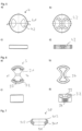
- the valve cartridge chosen as an embodiment according to figure 1 has a head piece 1, which is centrally penetrated by a spindle 2 guided radially in it.
- a reducing sleeve 5 is inserted into the head piece 1 and is sealed off from the head piece 1 by a first O-ring 91 and in which the spindle 2 is guided, which is sealed off from the reducing sleeve 5 by a second O-ring 92 .
- a valve can be actuated via the spindle 2 and comes to rest via a lip seal 90 on a shoulder 15 which is arranged in the head piece 1 and which is formed by a section 14 of the head piece 1 with a reduced internal diameter.
- the valve is formed by a control disk 3 and an inlet disk 4 .
- the control disk 3 is positively connected to the spindle 2 and guided radially in the head piece 1 .
- the inlet disk 4 is arranged in the head piece 1 , to which the lip seal 90 connects, which comes to rest on the shoulder 15 of the head piece 1 .
- the control disc 3 rests on the inlet disc 4 with a seal.
- the control disk 3 and the inlet disk 4 are designed as ceramic disks.
- the head piece 1 is designed as a turned brass part and consists of a cylindrical hollow body, in the outer lateral surface of which a groove 11 for receiving an O-ring 93 is introduced.
- the section 14 with the reduced inside diameter is arranged on the inside, with the inside diameter narrowing conically in the direction of the lip seal 90 , which has an annular surface that forms the shoulder 15 .
- a groove 13 for accommodating the lip seal 90 is formed in the inner lateral surface of the head piece at a distance from the shoulder 15 .
- two axial grooves 12 are arranged diametrically opposite one another on the inside, which extend from the end of the head piece 1 facing away from the shoulder 16 to the groove 13 .
- the axial grooves 12 accommodate the lugs 41 of the inlet disk 4, as a result of which this is held in the head piece 1 in a rotationally fixed manner.
- the spindle 2 is designed as a substantially cylindrical turned brass part and has an axial through bore 21 in the center for the passage of water. At the ends, two driver pins 22 are arranged diametrically opposite one another on the spindle for positive connection with the control disk 3 .
- a sealing groove 23 for receiving the second O-ring 92 adjoins the driving pin 22 .
- the spindle 21 is sealed off from the reducing sleeve 5 via the second O-ring 92 .
- the sealing groove 23 is followed by a cylindrical section 24 over which the spindle 1 is guided in the reducing sleeve 5 .
- a coupling section 25, which is designed in the form of an irregular hexagon, is formed around the circumference of the outer lateral surface of the spindle 2 approximately centrally.
- a peripheral annular web 26 which accommodates a sealing disk 95 , is arranged on its end face opposite the driver pin 22 .
- a sealing groove 27 for accommodating a further O-ring 94 is introduced into the spindle at a distance from the annular web 26 .
- the spindle 2 can be rotated in the head piece 1 via the reducing sleeve 5, but is arranged so that it can be displaced axially.
- the control disc 3 has an essentially barrel-shaped configuration, from which two circular sectors 31 lying opposite one another are excluded. In the exemplary embodiment, the circular sections 31 have an angle of approximately 90° on.
- the control disk 3 On its side facing the spindle 2 , the control disk 3 has an annular extension 32 .
- the ring-shaped shoulder 32 encompasses the driver pins 22 of the spindle 2.
- Recesses 33 are formed at the foot of the shoulder 32, in each of which a driver pin 22 fits.
- a depression 34 is made in the control disk 3 on its end face remote from the spindle 2 .
- the inlet disk 4 is of essentially cylindrical design and has two lugs 41 arranged diametrically opposite one another on its circumference. With the lugs 41, the inlet disk 4 engages in the axial grooves 12, which for this purpose are arranged on the inside in the head piece 1, as a result of which the inlet disk 4 is held in the head piece 1 in a rotationally fixed manner.
- the inlet disk 4 rests on the lip 902 of the lip seal 90 and has sector-shaped passage openings 42 . In the exemplary embodiment, two passage openings 42 are arranged diametrically opposite one another.
- the lip seal 90 is made of rubber and comprises an annular piece 901 on which a lip 902 is formed on its end face facing the inlet disk 4 .
- the lip 902 has a generally trapezoidal configuration in cross section.
- the lip 902 is at an angle to the horizontal.
- the outer surface of the lip 902 abuts the inlet disc 4 in a sealing manner.
- the ring piece 901 is provided with a collar 903 on the outside, which engages in the groove 13 of the head piece 1 .
- a bead 904 is formed on the inside of the annular piece 901 .
- the outside of the bead 904 lies flat on the shoulder 15 of the section 14 with the reduced internal diameter.
- the reducing sleeve 5 is designed as a substantially hollow-cylindrical brass part and has a cylindrical section 51 at its end facing the control disk 3, which is adjoined by an annular groove 52 for receiving the first O-ring 91, which is on its side opposite the cylindrical section 51 is delimited by a peripheral collar 53 which projects radially beyond the cylindrical section 51 and with which the reducing sleeve 5 rests on the head piece 1 .
- a section 54 Inside is in the reducing sleeve in the area of the cylindrical Section 51 is arranged a section 54 with an enlarged inner diameter, which forms the sealing surface for the second O-ring 92, via which the spindle 2 is sealed with respect to the reducing sleeve 5.
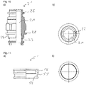
- FIG 8 a valve cartridge is shown in a further embodiment.
- a reducing sleeve 5' with a modified outer contour is arranged in this valve cartridge and is inserted completely into the head piece 1'.
- the modified reducing sleeve 5' is in figure 11 shown.
- the inner contour of this reducing sleeve 5' is unchanged and has a section 54 with an enlarged inner diameter, which forms a sealing surface for the second O-ring 92, via which the spindle 2 is sealed off from the reducing sleeve 5'.
- An annular groove 55 for accommodating the first O-ring 91 is introduced on the outside into the reducing sleeve 5 ′ in the area of the section 54 with the enlarged inner diameter.
- the first O-ring 91 is thus arranged at the same level as the second O-ring 92 .
- a groove 56 Spaced apart from the annular groove 55 is a groove 56 for receiving a grooved ring 57, via which the reducing sleeve 5' is held axially in the head piece 1'.
- a groove 16 is made in the head piece 1', in which the grooved ring 57 engages.
- the head piece 1′ apart from a circumferential chamfer 17 introduced on the inside on its side facing the spindle 2′—is unchanged.
- the spindle 2 ' is largely unchanged in this embodiment. Only on the side of the cylindrical section 24 facing the coupling section 25 does it additionally have a peripheral collar 28 which protrudes into the chamfer 17 of the head piece.
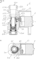
- FIG 12 a fitting housing 6 is shown, in which a valve cartridge according to the invention figure 1 is used.
- the fitting housing 6 comprises a water inlet section 61 and a water outlet section 62, through which a water inlet channel is guided, and a drive section 63.
- the water inlet section 61 has a cylindrical cartridge receptacle 611, which is delimited by a section 612 with a reduced internal diameter, through which a stop 613 is formed.
- the water inlet section 61 has an external thread 614 on the outside for connecting a water inlet line.
- the water drainage section 62 comprises, as part of the water inlet channel, a stepped bore 621, which has a first cylindrical section 622, which is followed by a second cylindrical section 623 with a reduced internal diameter, which merges into a conically tapering section 624, which opens into a third cylindrical section 625. which is followed by a fourth cylindrical, diameter-enlarged section 626, through which an annular contact surface 627 is formed.
- the water drain section 62 has an external thread 628 on the outside for connecting a water drain line.
- the drive section 63 is of essentially cylindrical design and opens into a gear chamber 64 which has a passage 641 which opens out between the water inlet section 61 and the water outlet section 62 . Furthermore, a measuring bore 631 is arranged in the drive section 63 and opens into the second section 623 of the stepped bore 621 .
- the valve cartridge is inserted into the cartridge receptacle 611, with the head piece 1 resting against the stop 613 via the collar 53 of the reducing sleeve 5.
- the reducing sleeve 5 is thus fixed axially between the head piece 1 and the stop 613 .
- the head piece 1 is sealed off from the cartridge receptacle 611 by the O-ring 93 .
- the spindle 2 of the valve cartridge protrudes through the section 612 of reduced internal diameter.
- a bevel gear 71 of a bevel gear 7 is mounted on the coupling section 25 and, in the exemplary embodiment, is formed from a hollow-cylindrical annular part 711 on which a bevel gear segment 712 is arranged on the outside.
- the bevel gear segment 712 spans an angle of 110° of the ring part 711. Depending on the maximum desired angle of rotation of the spindle 2, the bevel gear segment 712 can also span a smaller or a larger angle of the ring part 711.
- the ring part 711 has an inner contour of an irregular Hexagon, which corresponds to the outer contour of the coupling portion 25 on which it is arranged.
- the bevel gear 71 is thus positively connected to the spindle, with the bevel gear 71 protruding into the passage 641 with its bevel gear segment 712 .
- the spindle 2 rests against the contact surface 627 of the water drainage section 62 , against which it is sealed by the sealing washer 95 .
- the spindle 2 is radially sealed with respect to the fourth cylindrical section 626 of the stepped bore 621 via the O-ring 94 arranged in the sealing groove 27 .
- An electric motor 8 is arranged in the drive section 63 , the drive shaft 81 of which projects into the gear chamber 64 .
- a bevel pinion 72 is mounted on the drive shaft 81 and meshes with the bevel gear segment 712 of the bevel gear 71 .
- a control and regulating device (not shown) is provided to control the water flow flowing through the water drainage section 62, which is connected to a sensor, preferably a flow and/or temperature sensor, installed in the measuring bore 631 and via which the electric motor 8 can be controlled.
Landscapes
- Engineering & Computer Science (AREA)
- General Engineering & Computer Science (AREA)
- Mechanical Engineering (AREA)
- Sliding Valves (AREA)
- Details Of Valves (AREA)
- Multiple-Way Valves (AREA)
Priority Applications (8)
| Application Number | Priority Date | Filing Date | Title |
|---|---|---|---|
| HUE21191912A HUE065547T2 (hu) | 2021-08-18 | 2021-08-18 | Szelep kartus |
| ES21191912T ES2968026T3 (es) | 2021-08-18 | 2021-08-18 | Cartucho de válvula |
| EP21191912.1A EP4137722B1 (fr) | 2021-08-18 | 2021-08-18 | Cartouche de vanne |
| PCT/EP2022/072455 WO2023020913A1 (fr) | 2021-08-18 | 2022-08-10 | Cartouche de soupape |
| CN202280048671.8A CN117730219A (zh) | 2021-08-18 | 2022-08-10 | 阀筒 |
| US18/292,440 US12540677B2 (en) | 2021-08-18 | 2022-08-10 | Valve cartridge |
| DE112022001938.7T DE112022001938A5 (de) | 2021-08-18 | 2022-08-10 | Ventilkartusche |
| TW111130993A TW202403207A (zh) | 2021-08-18 | 2022-08-17 | 閥芯 |
Applications Claiming Priority (1)
| Application Number | Priority Date | Filing Date | Title |
|---|---|---|---|
| EP21191912.1A EP4137722B1 (fr) | 2021-08-18 | 2021-08-18 | Cartouche de vanne |
Publications (3)
| Publication Number | Publication Date |
|---|---|
| EP4137722A1 true EP4137722A1 (fr) | 2023-02-22 |
| EP4137722B1 EP4137722B1 (fr) | 2023-11-01 |
| EP4137722C0 EP4137722C0 (fr) | 2023-11-01 |
Family
ID=77398472
Family Applications (1)
| Application Number | Title | Priority Date | Filing Date |
|---|---|---|---|
| EP21191912.1A Active EP4137722B1 (fr) | 2021-08-18 | 2021-08-18 | Cartouche de vanne |
Country Status (8)
| Country | Link |
|---|---|
| US (1) | US12540677B2 (fr) |
| EP (1) | EP4137722B1 (fr) |
| CN (1) | CN117730219A (fr) |
| DE (1) | DE112022001938A5 (fr) |
| ES (1) | ES2968026T3 (fr) |
| HU (1) | HUE065547T2 (fr) |
| TW (1) | TW202403207A (fr) |
| WO (1) | WO2023020913A1 (fr) |
Citations (6)
| Publication number | Priority date | Publication date | Assignee | Title |
|---|---|---|---|---|
| DE3207895C2 (de) | 1982-03-05 | 1983-12-29 | Fa. Otto Flühs, 5880 Lüdenscheid | Ventiloberteil für Sanitärarmaturen |
| DE8715044U1 (de) | 1987-11-12 | 1988-01-14 | Flühs Drehtechnik GmbH, 5880 Lüdenscheid | Ventiloberteil für Sanitärarmaturen |
| DE3638180C2 (fr) | 1986-11-08 | 1988-08-18 | Fluehs Drehtechnik Gmbh, 5880 Luedenscheid, De | |
| EP0343312A2 (fr) * | 1988-05-26 | 1989-11-29 | F.LLI SAGLIO TROMBONE S.r.l. | Partie supérieure à disque céramique pour robinets d'eau |
| WO2020170193A1 (fr) * | 2019-02-21 | 2020-08-27 | Giacomini S.P.A. | Soupape pour commande hydraulique et équilibrage de débit de fluide |
| US20210199213A1 (en) * | 2018-09-19 | 2021-07-01 | Oblamatik Ag | Motor-driven axial-flow control valve |
Family Cites Families (29)
| Publication number | Priority date | Publication date | Assignee | Title |
|---|---|---|---|---|
| US3207181A (en) * | 1963-10-11 | 1965-09-21 | Willis N Elizabeth | Multiple orifice valve |
| US3426797A (en) * | 1965-10-20 | 1969-02-11 | Willis Oil Tool Co | Multiple orifice valve |
| US3958601A (en) * | 1975-07-18 | 1976-05-25 | Milwaukee Faucets, Inc. | Single lever faucet valve cartridge |
| US4596377A (en) * | 1984-08-20 | 1986-06-24 | Taylor Julian S | Restrictor valve operator |
| US4821765A (en) * | 1988-06-10 | 1989-04-18 | Kohler Co. | Valve for faucet or the like |
| US5025833A (en) * | 1988-10-31 | 1991-06-25 | Automatic Control Components, Inc. | Disk valve |
| US5020568A (en) * | 1989-01-30 | 1991-06-04 | Taylor Julian S | Unitized disc flow control assembly for a restrictor valve |
| US4901977A (en) * | 1989-06-02 | 1990-02-20 | Automatic Control Components, Inc. | Gear drive for a disk |
| US5025832A (en) * | 1990-09-14 | 1991-06-25 | Taylor Julian S | Multiple orifice rotatable disc in-line restrictor valve |
| US5365978A (en) * | 1992-07-27 | 1994-11-22 | Baker Hughes Incorporated | Top entry flow control valve with two sets of orifices |
| WO1999031416A1 (fr) * | 1997-12-18 | 1999-06-24 | Amerikam, Inc. | Valve en ligne |
| US6431211B1 (en) * | 2001-06-01 | 2002-08-13 | Shih-Ming Wang | Water controlling stem structure of a faucet |
| DE202005002894U1 (de) * | 2005-02-23 | 2005-05-19 | Flühs Drehtechnik GmbH | Ventiloberteil für Armaturen |
| DE202005003127U1 (de) * | 2005-02-26 | 2005-05-12 | Flühs Drehtechnik GmbH | Ventiloberteil |
| KR100787512B1 (ko) * | 2005-09-06 | 2007-12-21 | 김종구 | 수도밸브카트리지 |
| US20080054210A1 (en) * | 2006-08-31 | 2008-03-06 | Smith Matthew S | Valve cartridge |
| EP1918619A1 (fr) * | 2006-11-02 | 2008-05-07 | Kwc Ag | Robinet sanitaire |
| US20090205728A1 (en) * | 2008-02-19 | 2009-08-20 | Weatherford/Lamb, Inc. | Disc Arrangement for Drilling or Production Choke or Valve |
| WO2014010453A1 (fr) * | 2012-07-13 | 2014-01-16 | Smc株式会社 | Raccord de tuyau |
| US9404561B2 (en) * | 2013-05-16 | 2016-08-02 | Valve Systems International Llc | Rotary-to-linear motion actuator having a helical bevel gear and method of use thereof |
| US9103421B2 (en) * | 2013-05-16 | 2015-08-11 | Lobo Engineering PLC | Rotary-to-linear motion actuator having a helical bevel gear and method of use thereof |
| US9400057B2 (en) * | 2014-04-02 | 2016-07-26 | Griswold Controls, Llc | Axially aligned rotationally adjustable flow control valve |
| WO2016131472A1 (fr) * | 2015-02-16 | 2016-08-25 | Oblamatik Ag | Soupape pour réguler le flux d'eau dans une conduite sanitaire |
| US10941870B1 (en) * | 2016-12-12 | 2021-03-09 | Agi Industries, Inc. | Fluid throttling valve |
| DE102017102841A1 (de) * | 2017-02-13 | 2018-08-16 | Otto Egelhof Gmbh & Co. Kg | Mehrwegventil zur Steuerung eines Kältemittelkreislaufs |
| EP3702651B1 (fr) * | 2019-02-28 | 2021-02-24 | Flühs Drehtechnik GmbH | Partie supérieure de soupape pour robinetteries sanitaires |
| FR3097610B1 (fr) * | 2019-06-20 | 2021-08-06 | Moving Magnet Tech | Vanne de réglage compacte |
| EP4089304B1 (fr) * | 2021-05-12 | 2023-12-27 | Flühs Drehtechnik GmbH | Cartouche de vanne |
| US11629787B1 (en) * | 2021-10-22 | 2023-04-18 | Agi Industries, Inc. | Fluid valve |
-
2021
- 2021-08-18 HU HUE21191912A patent/HUE065547T2/hu unknown
- 2021-08-18 ES ES21191912T patent/ES2968026T3/es active Active
- 2021-08-18 EP EP21191912.1A patent/EP4137722B1/fr active Active
-
2022
- 2022-08-10 WO PCT/EP2022/072455 patent/WO2023020913A1/fr not_active Ceased
- 2022-08-10 CN CN202280048671.8A patent/CN117730219A/zh active Pending
- 2022-08-10 US US18/292,440 patent/US12540677B2/en active Active
- 2022-08-10 DE DE112022001938.7T patent/DE112022001938A5/de active Pending
- 2022-08-17 TW TW111130993A patent/TW202403207A/zh unknown
Patent Citations (6)
| Publication number | Priority date | Publication date | Assignee | Title |
|---|---|---|---|---|
| DE3207895C2 (de) | 1982-03-05 | 1983-12-29 | Fa. Otto Flühs, 5880 Lüdenscheid | Ventiloberteil für Sanitärarmaturen |
| DE3638180C2 (fr) | 1986-11-08 | 1988-08-18 | Fluehs Drehtechnik Gmbh, 5880 Luedenscheid, De | |
| DE8715044U1 (de) | 1987-11-12 | 1988-01-14 | Flühs Drehtechnik GmbH, 5880 Lüdenscheid | Ventiloberteil für Sanitärarmaturen |
| EP0343312A2 (fr) * | 1988-05-26 | 1989-11-29 | F.LLI SAGLIO TROMBONE S.r.l. | Partie supérieure à disque céramique pour robinets d'eau |
| US20210199213A1 (en) * | 2018-09-19 | 2021-07-01 | Oblamatik Ag | Motor-driven axial-flow control valve |
| WO2020170193A1 (fr) * | 2019-02-21 | 2020-08-27 | Giacomini S.P.A. | Soupape pour commande hydraulique et équilibrage de débit de fluide |
Also Published As
| Publication number | Publication date |
|---|---|
| US12540677B2 (en) | 2026-02-03 |
| ES2968026T3 (es) | 2024-05-06 |
| CN117730219A (zh) | 2024-03-19 |
| DE112022001938A5 (de) | 2024-03-14 |
| HUE065547T2 (hu) | 2024-06-28 |
| TW202403207A (zh) | 2024-01-16 |
| WO2023020913A1 (fr) | 2023-02-23 |
| EP4137722B1 (fr) | 2023-11-01 |
| US20250075802A1 (en) | 2025-03-06 |
| EP4137722C0 (fr) | 2023-11-01 |
Similar Documents
| Publication | Publication Date | Title |
|---|---|---|
| EP3221621B1 (fr) | Partie supérieure de soupape | |
| EP3420430B1 (fr) | Vanne de mélange thermostatique | |
| DE3421653C2 (de) | Ventil | |
| EP1696158A1 (fr) | Tête de robinet | |
| EP3062002A1 (fr) | Partie supérieure de soupape | |
| EP4089304B1 (fr) | Cartouche de vanne | |
| CH646502A5 (de) | Drehschieberventilanordnung. | |
| DE102007041753A1 (de) | Vorrichtung zur Drosselung des freien Querschnittes einer Dampfleitung oder dergleichen | |
| EP1462692B1 (fr) | Tête de robinet | |
| EP4137722B1 (fr) | Cartouche de vanne | |
| EP3265704B1 (fr) | Pièce supérieure de soupape pour robinetterie | |
| WO2013010845A1 (fr) | Partie supérieure de soupape pour robinetterie | |
| EP3591271B1 (fr) | Partie supérieure de soupape | |
| DE202021104414U1 (de) | Ventilkartusche | |
| EP1342996B1 (fr) | Connexion pour compteur d'eau | |
| DE102006027558B4 (de) | Ventiloberteil | |
| EP2696117B1 (fr) | Partie supérieure de soupape | |
| EP3062001B1 (fr) | Partie supérieure de soupape | |
| EP3693643B1 (fr) | Partie supérieure de soupape pour robinetteries sanitaires | |
| DE20008679U1 (de) | Ventiloberteil für Armaturen | |
| DE19653419C2 (de) | Ventiloberteil | |
| EP4650632A1 (fr) | Cartouche de robinet mitigeur | |
| DE202024102491U1 (de) | Mischventilkartusche | |
| DE202018103777U1 (de) | Ventiloberteil | |
| DE20309724U1 (de) | Ventiloberteil für Armaturen |
Legal Events
| Date | Code | Title | Description |
|---|---|---|---|
| PUAI | Public reference made under article 153(3) epc to a published international application that has entered the european phase |
Free format text: ORIGINAL CODE: 0009012 |
|
| STAA | Information on the status of an ep patent application or granted ep patent |
Free format text: STATUS: REQUEST FOR EXAMINATION WAS MADE |
|
| 17P | Request for examination filed |
Effective date: 20220630 |
|
| AK | Designated contracting states |
Kind code of ref document: A1 Designated state(s): AL AT BE BG CH CY CZ DE DK EE ES FI FR GB GR HR HU IE IS IT LI LT LU LV MC MK MT NL NO PL PT RO RS SE SI SK SM TR |
|
| GRAP | Despatch of communication of intention to grant a patent |
Free format text: ORIGINAL CODE: EPIDOSNIGR1 |
|
| STAA | Information on the status of an ep patent application or granted ep patent |
Free format text: STATUS: GRANT OF PATENT IS INTENDED |
|
| RIC1 | Information provided on ipc code assigned before grant |
Ipc: F16K 31/04 20060101ALI20230524BHEP Ipc: F16K 31/53 20060101ALI20230524BHEP Ipc: F16K 27/04 20060101ALI20230524BHEP Ipc: F16K 3/08 20060101AFI20230524BHEP |
|
| INTG | Intention to grant announced |
Effective date: 20230621 |
|
| GRAS | Grant fee paid |
Free format text: ORIGINAL CODE: EPIDOSNIGR3 |
|
| GRAA | (expected) grant |
Free format text: ORIGINAL CODE: 0009210 |
|
| STAA | Information on the status of an ep patent application or granted ep patent |
Free format text: STATUS: THE PATENT HAS BEEN GRANTED |
|
| AK | Designated contracting states |
Kind code of ref document: B1 Designated state(s): AL AT BE BG CH CY CZ DE DK EE ES FI FR GB GR HR HU IE IS IT LI LT LU LV MC MK MT NL NO PL PT RO RS SE SI SK SM TR |
|
| REG | Reference to a national code |
Ref country code: GB Ref legal event code: FG4D Free format text: NOT ENGLISH |
|
| REG | Reference to a national code |
Ref country code: CH Ref legal event code: EP |
|
| REG | Reference to a national code |
Ref country code: IE Ref legal event code: FG4D Free format text: LANGUAGE OF EP DOCUMENT: GERMAN |
|
| REG | Reference to a national code |
Ref country code: DE Ref legal event code: R096 Ref document number: 502021001838 Country of ref document: DE |
|
| U01 | Request for unitary effect filed |
Effective date: 20231130 |
|
| U07 | Unitary effect registered |
Designated state(s): AT BE BG DE DK EE FI FR IT LT LU LV MT NL PT SE SI Effective date: 20231207 |
|
| PG25 | Lapsed in a contracting state [announced via postgrant information from national office to epo] |
Ref country code: GR Free format text: LAPSE BECAUSE OF FAILURE TO SUBMIT A TRANSLATION OF THE DESCRIPTION OR TO PAY THE FEE WITHIN THE PRESCRIBED TIME-LIMIT Effective date: 20240202 |
|
| PG25 | Lapsed in a contracting state [announced via postgrant information from national office to epo] |
Ref country code: IS Free format text: LAPSE BECAUSE OF FAILURE TO SUBMIT A TRANSLATION OF THE DESCRIPTION OR TO PAY THE FEE WITHIN THE PRESCRIBED TIME-LIMIT Effective date: 20240301 |
|
| PG25 | Lapsed in a contracting state [announced via postgrant information from national office to epo] |
Ref country code: IS Free format text: LAPSE BECAUSE OF FAILURE TO SUBMIT A TRANSLATION OF THE DESCRIPTION OR TO PAY THE FEE WITHIN THE PRESCRIBED TIME-LIMIT Effective date: 20240301 Ref country code: GR Free format text: LAPSE BECAUSE OF FAILURE TO SUBMIT A TRANSLATION OF THE DESCRIPTION OR TO PAY THE FEE WITHIN THE PRESCRIBED TIME-LIMIT Effective date: 20240202 |
|
| REG | Reference to a national code |
Ref country code: ES Ref legal event code: FG2A Ref document number: 2968026 Country of ref document: ES Kind code of ref document: T3 Effective date: 20240506 |
|
| PG25 | Lapsed in a contracting state [announced via postgrant information from national office to epo] |
Ref country code: RS Free format text: LAPSE BECAUSE OF FAILURE TO SUBMIT A TRANSLATION OF THE DESCRIPTION OR TO PAY THE FEE WITHIN THE PRESCRIBED TIME-LIMIT Effective date: 20231101 Ref country code: PL Free format text: LAPSE BECAUSE OF FAILURE TO SUBMIT A TRANSLATION OF THE DESCRIPTION OR TO PAY THE FEE WITHIN THE PRESCRIBED TIME-LIMIT Effective date: 20231101 Ref country code: NO Free format text: LAPSE BECAUSE OF FAILURE TO SUBMIT A TRANSLATION OF THE DESCRIPTION OR TO PAY THE FEE WITHIN THE PRESCRIBED TIME-LIMIT Effective date: 20240201 Ref country code: HR Free format text: LAPSE BECAUSE OF FAILURE TO SUBMIT A TRANSLATION OF THE DESCRIPTION OR TO PAY THE FEE WITHIN THE PRESCRIBED TIME-LIMIT Effective date: 20231101 |
|
| REG | Reference to a national code |
Ref country code: HU Ref legal event code: AG4A Ref document number: E065547 Country of ref document: HU |
|
| PG25 | Lapsed in a contracting state [announced via postgrant information from national office to epo] |
Ref country code: CZ Free format text: LAPSE BECAUSE OF FAILURE TO SUBMIT A TRANSLATION OF THE DESCRIPTION OR TO PAY THE FEE WITHIN THE PRESCRIBED TIME-LIMIT Effective date: 20231101 |
|
| PG25 | Lapsed in a contracting state [announced via postgrant information from national office to epo] |
Ref country code: SK Free format text: LAPSE BECAUSE OF FAILURE TO SUBMIT A TRANSLATION OF THE DESCRIPTION OR TO PAY THE FEE WITHIN THE PRESCRIBED TIME-LIMIT Effective date: 20231101 |
|
| PG25 | Lapsed in a contracting state [announced via postgrant information from national office to epo] |
Ref country code: SM Free format text: LAPSE BECAUSE OF FAILURE TO SUBMIT A TRANSLATION OF THE DESCRIPTION OR TO PAY THE FEE WITHIN THE PRESCRIBED TIME-LIMIT Effective date: 20231101 Ref country code: SK Free format text: LAPSE BECAUSE OF FAILURE TO SUBMIT A TRANSLATION OF THE DESCRIPTION OR TO PAY THE FEE WITHIN THE PRESCRIBED TIME-LIMIT Effective date: 20231101 Ref country code: CZ Free format text: LAPSE BECAUSE OF FAILURE TO SUBMIT A TRANSLATION OF THE DESCRIPTION OR TO PAY THE FEE WITHIN THE PRESCRIBED TIME-LIMIT Effective date: 20231101 |
|
| REG | Reference to a national code |
Ref country code: DE Ref legal event code: R097 Ref document number: 502021001838 Country of ref document: DE |
|
| PLBE | No opposition filed within time limit |
Free format text: ORIGINAL CODE: 0009261 |
|
| STAA | Information on the status of an ep patent application or granted ep patent |
Free format text: STATUS: NO OPPOSITION FILED WITHIN TIME LIMIT |
|
| U20 | Renewal fee for the european patent with unitary effect paid |
Year of fee payment: 4 Effective date: 20240806 |
|
| 26N | No opposition filed |
Effective date: 20240802 |
|
| REG | Reference to a national code |
Ref country code: CH Ref legal event code: PL |
|
| PG25 | Lapsed in a contracting state [announced via postgrant information from national office to epo] |
Ref country code: CH Free format text: LAPSE BECAUSE OF NON-PAYMENT OF DUE FEES Effective date: 20240831 Ref country code: MC Free format text: LAPSE BECAUSE OF FAILURE TO SUBMIT A TRANSLATION OF THE DESCRIPTION OR TO PAY THE FEE WITHIN THE PRESCRIBED TIME-LIMIT Effective date: 20231101 |
|
| PG25 | Lapsed in a contracting state [announced via postgrant information from national office to epo] |
Ref country code: IE Free format text: LAPSE BECAUSE OF NON-PAYMENT OF DUE FEES Effective date: 20240818 |
|
| U20 | Renewal fee for the european patent with unitary effect paid |
Year of fee payment: 5 Effective date: 20250729 |
|
| PGFP | Annual fee paid to national office [announced via postgrant information from national office to epo] |
Ref country code: HU Payment date: 20250814 Year of fee payment: 5 |
|
| PGFP | Annual fee paid to national office [announced via postgrant information from national office to epo] |
Ref country code: ES Payment date: 20250917 Year of fee payment: 5 |
|
| PGFP | Annual fee paid to national office [announced via postgrant information from national office to epo] |
Ref country code: TR Payment date: 20250811 Year of fee payment: 5 |
|
| PG25 | Lapsed in a contracting state [announced via postgrant information from national office to epo] |
Ref country code: RO Free format text: LAPSE BECAUSE OF FAILURE TO SUBMIT A TRANSLATION OF THE DESCRIPTION OR TO PAY THE FEE WITHIN THE PRESCRIBED TIME-LIMIT Effective date: 20231101 |
|
| PG25 | Lapsed in a contracting state [announced via postgrant information from national office to epo] |
Ref country code: CY Free format text: LAPSE BECAUSE OF FAILURE TO SUBMIT A TRANSLATION OF THE DESCRIPTION OR TO PAY THE FEE WITHIN THE PRESCRIBED TIME-LIMIT; INVALID AB INITIO Effective date: 20210818 |