EP4140689A1 - Matériau isolant pour bobine à fente d'une machine rotative et son procédé de moulage - Google Patents
Matériau isolant pour bobine à fente d'une machine rotative et son procédé de moulage Download PDFInfo
- Publication number
- EP4140689A1 EP4140689A1 EP21791882.0A EP21791882A EP4140689A1 EP 4140689 A1 EP4140689 A1 EP 4140689A1 EP 21791882 A EP21791882 A EP 21791882A EP 4140689 A1 EP4140689 A1 EP 4140689A1
- Authority
- EP
- European Patent Office
- Prior art keywords
- flanges
- insulating member
- flange
- slot coil
- molten resin
- Prior art date
- Legal status (The legal status is an assumption and is not a legal conclusion. Google has not performed a legal analysis and makes no representation as to the accuracy of the status listed.)
- Withdrawn
Links
- 238000000465 moulding Methods 0.000 title claims description 36
- 238000000034 method Methods 0.000 title claims description 21
- 239000011810 insulating material Substances 0.000 title 1
- 229920003002 synthetic resin Polymers 0.000 claims abstract description 58
- 239000000057 synthetic resin Substances 0.000 claims abstract description 58
- 229920001169 thermoplastic Polymers 0.000 claims abstract description 57
- 239000004416 thermosoftening plastic Substances 0.000 claims abstract description 57
- 230000002093 peripheral effect Effects 0.000 claims abstract description 53
- 238000005192 partition Methods 0.000 claims abstract description 41
- 229920005989 resin Polymers 0.000 claims description 69
- 239000011347 resin Substances 0.000 claims description 69
- 238000001746 injection moulding Methods 0.000 claims description 36
- WABPQHHGFIMREM-UHFFFAOYSA-N lead(0) Chemical compound [Pb] WABPQHHGFIMREM-UHFFFAOYSA-N 0.000 claims description 19
- 125000003118 aryl group Chemical group 0.000 claims description 5
- 239000007788 liquid Substances 0.000 claims description 5
- 229920000728 polyester Polymers 0.000 claims description 5
- 238000010292 electrical insulation Methods 0.000 claims description 4
- 230000002401 inhibitory effect Effects 0.000 claims description 3
- 238000002347 injection Methods 0.000 claims description 3
- 239000007924 injection Substances 0.000 claims description 3
- 230000036961 partial effect Effects 0.000 description 8
- 239000002966 varnish Substances 0.000 description 8
- 238000009413 insulation Methods 0.000 description 6
- RYGMFSIKBFXOCR-UHFFFAOYSA-N Copper Chemical compound [Cu] RYGMFSIKBFXOCR-UHFFFAOYSA-N 0.000 description 3
- 238000006243 chemical reaction Methods 0.000 description 1
- 229910052802 copper Inorganic materials 0.000 description 1
- 239000010949 copper Substances 0.000 description 1
- 229920006038 crystalline resin Polymers 0.000 description 1
- 230000000694 effects Effects 0.000 description 1
- 230000000452 restraining effect Effects 0.000 description 1
- 238000007711 solidification Methods 0.000 description 1
- 230000008023 solidification Effects 0.000 description 1
- 230000003068 static effect Effects 0.000 description 1
Images






Classifications
-
- B—PERFORMING OPERATIONS; TRANSPORTING
- B29—WORKING OF PLASTICS; WORKING OF SUBSTANCES IN A PLASTIC STATE IN GENERAL
- B29C—SHAPING OR JOINING OF PLASTICS; SHAPING OF MATERIAL IN A PLASTIC STATE, NOT OTHERWISE PROVIDED FOR; AFTER-TREATMENT OF THE SHAPED PRODUCTS, e.g. REPAIRING
- B29C45/00—Injection moulding, i.e. forcing the required volume of moulding material through a nozzle into a closed mould; Apparatus therefor
- B29C45/0046—Details relating to the filling pattern or flow paths or flow characteristics of moulding material in the mould cavity
-
- H—ELECTRICITY
- H02—GENERATION; CONVERSION OR DISTRIBUTION OF ELECTRIC POWER
- H02K—DYNAMO-ELECTRIC MACHINES
- H02K3/00—Details of windings
- H02K3/32—Windings characterised by the shape, form or construction of the insulation
- H02K3/34—Windings characterised by the shape, form or construction of the insulation between conductors or between conductor and core, e.g. slot insulation
- H02K3/345—Windings characterised by the shape, form or construction of the insulation between conductors or between conductor and core, e.g. slot insulation between conductor and core, e.g. slot insulation
-
- B—PERFORMING OPERATIONS; TRANSPORTING
- B29—WORKING OF PLASTICS; WORKING OF SUBSTANCES IN A PLASTIC STATE IN GENERAL
- B29C—SHAPING OR JOINING OF PLASTICS; SHAPING OF MATERIAL IN A PLASTIC STATE, NOT OTHERWISE PROVIDED FOR; AFTER-TREATMENT OF THE SHAPED PRODUCTS, e.g. REPAIRING
- B29C45/00—Injection moulding, i.e. forcing the required volume of moulding material through a nozzle into a closed mould; Apparatus therefor
- B29C45/0025—Preventing defects on the moulded article, e.g. weld lines, shrinkage marks
-
- B—PERFORMING OPERATIONS; TRANSPORTING
- B29—WORKING OF PLASTICS; WORKING OF SUBSTANCES IN A PLASTIC STATE IN GENERAL
- B29C—SHAPING OR JOINING OF PLASTICS; SHAPING OF MATERIAL IN A PLASTIC STATE, NOT OTHERWISE PROVIDED FOR; AFTER-TREATMENT OF THE SHAPED PRODUCTS, e.g. REPAIRING
- B29C45/00—Injection moulding, i.e. forcing the required volume of moulding material through a nozzle into a closed mould; Apparatus therefor
- B29C45/17—Component parts, details or accessories; Auxiliary operations
- B29C45/20—Injection nozzles
-
- B—PERFORMING OPERATIONS; TRANSPORTING
- B29—WORKING OF PLASTICS; WORKING OF SUBSTANCES IN A PLASTIC STATE IN GENERAL
- B29C—SHAPING OR JOINING OF PLASTICS; SHAPING OF MATERIAL IN A PLASTIC STATE, NOT OTHERWISE PROVIDED FOR; AFTER-TREATMENT OF THE SHAPED PRODUCTS, e.g. REPAIRING
- B29C45/00—Injection moulding, i.e. forcing the required volume of moulding material through a nozzle into a closed mould; Apparatus therefor
- B29C45/17—Component parts, details or accessories; Auxiliary operations
- B29C45/26—Moulds
- B29C45/2624—Moulds provided with a multiplicity of wall-like cavities connected to a common cavity, e.g. for battery cases
-
- B—PERFORMING OPERATIONS; TRANSPORTING
- B29—WORKING OF PLASTICS; WORKING OF SUBSTANCES IN A PLASTIC STATE IN GENERAL
- B29C—SHAPING OR JOINING OF PLASTICS; SHAPING OF MATERIAL IN A PLASTIC STATE, NOT OTHERWISE PROVIDED FOR; AFTER-TREATMENT OF THE SHAPED PRODUCTS, e.g. REPAIRING
- B29C45/00—Injection moulding, i.e. forcing the required volume of moulding material through a nozzle into a closed mould; Apparatus therefor
- B29C45/17—Component parts, details or accessories; Auxiliary operations
- B29C45/26—Moulds
- B29C45/27—Sprue channels ; Runner channels or runner nozzles
-
- B—PERFORMING OPERATIONS; TRANSPORTING
- B29—WORKING OF PLASTICS; WORKING OF SUBSTANCES IN A PLASTIC STATE IN GENERAL
- B29C—SHAPING OR JOINING OF PLASTICS; SHAPING OF MATERIAL IN A PLASTIC STATE, NOT OTHERWISE PROVIDED FOR; AFTER-TREATMENT OF THE SHAPED PRODUCTS, e.g. REPAIRING
- B29C45/00—Injection moulding, i.e. forcing the required volume of moulding material through a nozzle into a closed mould; Apparatus therefor
- B29C45/17—Component parts, details or accessories; Auxiliary operations
- B29C45/26—Moulds
- B29C45/27—Sprue channels ; Runner channels or runner nozzles
- B29C45/2701—Details not specific to hot or cold runner channels
- B29C45/2708—Gates
-
- H—ELECTRICITY
- H02—GENERATION; CONVERSION OR DISTRIBUTION OF ELECTRIC POWER
- H02K—DYNAMO-ELECTRIC MACHINES
- H02K15/00—Processes or apparatus specially adapted for manufacturing, assembling, maintaining or repairing of dynamo-electric machines
- H02K15/08—Forming windings by laying conductors into or around core parts
- H02K15/085—Forming windings by laying conductors into or around core parts by laying conductors into slotted stators
-
- H—ELECTRICITY
- H02—GENERATION; CONVERSION OR DISTRIBUTION OF ELECTRIC POWER
- H02K—DYNAMO-ELECTRIC MACHINES
- H02K15/00—Processes or apparatus specially adapted for manufacturing, assembling, maintaining or repairing of dynamo-electric machines
- H02K15/10—Applying solid insulation to windings, stators or rotors, e.g. applying insulating tapes
-
- H—ELECTRICITY
- H02—GENERATION; CONVERSION OR DISTRIBUTION OF ELECTRIC POWER
- H02K—DYNAMO-ELECTRIC MACHINES
- H02K15/00—Processes or apparatus specially adapted for manufacturing, assembling, maintaining or repairing of dynamo-electric machines
- H02K15/10—Applying solid insulation to windings, stators or rotors, e.g. applying insulating tapes
- H02K15/105—Applying solid insulation to windings, stators or rotors, e.g. applying insulating tapes to the windings
-
- H—ELECTRICITY
- H02—GENERATION; CONVERSION OR DISTRIBUTION OF ELECTRIC POWER
- H02K—DYNAMO-ELECTRIC MACHINES
- H02K15/00—Processes or apparatus specially adapted for manufacturing, assembling, maintaining or repairing of dynamo-electric machines
- H02K15/12—Impregnating, moulding insulation, heating or drying of windings, stators, rotors or machines
-
- H—ELECTRICITY
- H02—GENERATION; CONVERSION OR DISTRIBUTION OF ELECTRIC POWER
- H02K—DYNAMO-ELECTRIC MACHINES
- H02K3/00—Details of windings
- H02K3/32—Windings characterised by the shape, form or construction of the insulation
- H02K3/34—Windings characterised by the shape, form or construction of the insulation between conductors or between conductor and core, e.g. slot insulation
-
- B—PERFORMING OPERATIONS; TRANSPORTING
- B29—WORKING OF PLASTICS; WORKING OF SUBSTANCES IN A PLASTIC STATE IN GENERAL
- B29C—SHAPING OR JOINING OF PLASTICS; SHAPING OF MATERIAL IN A PLASTIC STATE, NOT OTHERWISE PROVIDED FOR; AFTER-TREATMENT OF THE SHAPED PRODUCTS, e.g. REPAIRING
- B29C45/00—Injection moulding, i.e. forcing the required volume of moulding material through a nozzle into a closed mould; Apparatus therefor
- B29C45/0025—Preventing defects on the moulded article, e.g. weld lines, shrinkage marks
- B29C2045/0027—Gate or gate mark locations
-
- B—PERFORMING OPERATIONS; TRANSPORTING
- B29—WORKING OF PLASTICS; WORKING OF SUBSTANCES IN A PLASTIC STATE IN GENERAL
- B29C—SHAPING OR JOINING OF PLASTICS; SHAPING OF MATERIAL IN A PLASTIC STATE, NOT OTHERWISE PROVIDED FOR; AFTER-TREATMENT OF THE SHAPED PRODUCTS, e.g. REPAIRING
- B29C45/00—Injection moulding, i.e. forcing the required volume of moulding material through a nozzle into a closed mould; Apparatus therefor
- B29C45/17—Component parts, details or accessories; Auxiliary operations
- B29C45/38—Cutting-off equipment for sprues or ingates
-
- B—PERFORMING OPERATIONS; TRANSPORTING
- B29—WORKING OF PLASTICS; WORKING OF SUBSTANCES IN A PLASTIC STATE IN GENERAL
- B29C—SHAPING OR JOINING OF PLASTICS; SHAPING OF MATERIAL IN A PLASTIC STATE, NOT OTHERWISE PROVIDED FOR; AFTER-TREATMENT OF THE SHAPED PRODUCTS, e.g. REPAIRING
- B29C45/00—Injection moulding, i.e. forcing the required volume of moulding material through a nozzle into a closed mould; Apparatus therefor
- B29C45/17—Component parts, details or accessories; Auxiliary operations
- B29C45/76—Measuring, controlling or regulating
- B29C45/77—Measuring, controlling or regulating of velocity or pressure of moulding material
-
- B—PERFORMING OPERATIONS; TRANSPORTING
- B29—WORKING OF PLASTICS; WORKING OF SUBSTANCES IN A PLASTIC STATE IN GENERAL
- B29K—INDEXING SCHEME ASSOCIATED WITH SUBCLASSES B29B, B29C OR B29D, RELATING TO MOULDING MATERIALS OR TO MATERIALS FOR MOULDS, REINFORCEMENTS, FILLERS OR PREFORMED PARTS, e.g. INSERTS
- B29K2067/00—Use of polyesters or derivatives thereof, as moulding material
-
- B—PERFORMING OPERATIONS; TRANSPORTING
- B29—WORKING OF PLASTICS; WORKING OF SUBSTANCES IN A PLASTIC STATE IN GENERAL
- B29L—INDEXING SCHEME ASSOCIATED WITH SUBCLASS B29C, RELATING TO PARTICULAR ARTICLES
- B29L2031/00—Other particular articles
- B29L2031/34—Electrical apparatus, e.g. sparking plugs or parts thereof
- B29L2031/3412—Insulators
-
- H—ELECTRICITY
- H02—GENERATION; CONVERSION OR DISTRIBUTION OF ELECTRIC POWER
- H02K—DYNAMO-ELECTRIC MACHINES
- H02K2213/00—Specific aspects, not otherwise provided for and not covered by codes H02K2201/00 - H02K2211/00
- H02K2213/03—Machines characterised by numerical values, ranges, mathematical expressions or similar information
-
- H—ELECTRICITY
- H02—GENERATION; CONVERSION OR DISTRIBUTION OF ELECTRIC POWER
- H02K—DYNAMO-ELECTRIC MACHINES
- H02K3/00—Details of windings
- H02K3/30—Windings characterised by the insulating material
Definitions
- the present disclosure relates to an insulating member for a slot coil of a rotary electric machine and a method for molding the same. More specifically, the present disclosure relates to an insulating member for a slot coil of a rotary electric machine and a method for molding the same used for insulating lead wire disposed on a stator of a rotary electric machine.
- a rotary electric machine that have a segment coil in a stator of a rotary electric machine such as a motor, electric generator, etc.
- Lead wire of a segment coil that has a square sectional shape or a rectangular sectional shape (in flat type wire) for improving efficiency of a motor (Patent Document 1, Patent Document 2).
- a slot coil for this segment coil is also proposed.
- an insulating member is formed through injection molding of resin, and then coil of flat type wire is inserted into a slot of a stator to be assembled as a segment coil (Patent Document 3).
- a flange is formed on an end of the insulating member and gap between the insulating member and the slot is sealed with the flange, thus varnish for fixing wire is prevented from flowing.
- the present disclosure adopts the following means for solving the above problems. That is, in an insulating member for a slot coil of a rotary electric machine according to a first aspect of the present disclosure, said slot coil being fitted into a slot provided in a stator or rotor of the rotary electric machine and composed of:
- the insulating member for a slot coil of a rotary electric machine according to a second aspect of the present disclosure is characterized in that, in the first aspect of the present disclosure,
- the insulating member for a slot coil of a rotary electric machine is characterized in that, in the first aspect or the second aspect of the present disclosure,
- a method for molding the insulating member for a slot coil of a rotary electric machine is characterized in that, in a method for molding the insulating member for a slot coil of a rotary electric machine in the first or second aspect, lug part flanges are disposed to be integral with said flange/flanges for causing molten resin to flow through gates for injecting the molten resin, after then to convert direction of flow by 90° twice and then to flow into said flange/flanges when the insulating member is formed by injection molding of molten resin.
- the method for molding the insulating member for a slot coil of a rotary electric machine according to a fifth aspect of the present disclosure is characterized in that, in a method for molding the insulating member for a slot coil of a rotary electric machine in the first aspect or second aspect, the insulating member is formed by injection molding through a fan gate/fan gates provided on the long side of said flange/flanges and having same width with the long side when the insulating member is formed by injection molding.
- the method for molding the insulating member for a slot coil of a rotary electric machine according to a sixth aspect of the present disclosure is characterized in that, in the fourth aspect of the present disclosure, each of said flange/flanges has a molten resin basin disposed at one end of said flange/flanges for storing the molten resin in time of injection molding.
- the method for molding the insulating member for a slot coil of a rotary electric machine according to a seventh aspect of the present disclosure is characterized in that, in the fifth aspect of the present disclosure, a flow control member for inhibiting or delaying flow of injected molten resin is disposed in said fan gate/fan gates, and also provided with:
- the method for molding the insulating member for a slot coil of a rotary electric machine according to an eighth aspect of the present disclosure is characterized in that, in the sixth or seventh aspect of the present disclosure, an injection molding machine used for injection molding is a high-speed injection molding machine with which injection speed attains its peak within 0.1 sec.
- a thick flange is formed on the outer periphery of a through-hole for inserting lead wire. Consequently, the flange serves as a runner in molding of an insulating member and thermoplastic synthetic resin flows smoothly through the outer peripheral wall and partition wall, so that smooth molded articles having a precise shape can be formed.
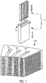
- Fig.1 is an isometric projection view showing a main portion of a stator of a rotary electric machine provided with an insulating member for a slot coil of the present disclosure.
- slot coils 12 each composed of an insulating member 1 and lead wire 11, are fitted in plurality of slots 101 formed radially on a stator 100 of a rotary electric machine.
- Fig. 2 is an isometric projection view showing whole of an insulating member for a slot coil of a first embodiment of the present disclosure
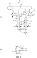
- Fig. 3 (a) is a view of Fig. 2 as seen in a direction of an arrow P, in Fig.
- FIG. 3 is a partial enlarged view of a portion Q of (a) in Fig. 3 and Fig. 4 is a sectional view of Fig. 2 taken along a line A-A.
- Figs. 2 to 4 six through-holes 13 for inserting lead wire 11 having a rectangular cross section are formed in an insulating member 1 according to the first embodiment of the present disclosure.
- This insulating member 1 serves for fixing the lead wire and for electrically insulating the lead wire.
- Each through-hole 13 is formed so as to have a rectangular cross section similar to the cross-sectional shape of the lead wire 11 and these through-holes are disposed parallel to each other.
- the lead wire 11 in the embodiment is a flat type copper wire (which means "a flat type copper wire", etc., defined in JIS, etc.) and lead wire without insulating film or covered with resin, etc., (of about 60 to 100 ⁇ ) is used.
- the insulating member 1 is formed through injection molding of synthetic resin having high electrical insulation and heat resistance.
- the insulating member 1 has outer peripheral walls 131, 132 and partition walls 133 of the through-holes 13 and these walls are formed to have a same thickness (a, b, c), being thin as of 0.15 mm to 0.55 mm in this embodiment.
- flanges 14 are formed on outer periphery at the upper end of the through-hole 13.
- the flanges 14 are made up of two flanges 15, 15 on the long side and two lug part flanges 16, 16.
- the flanges 15, 15 on the long side are formed on the two long sides along whole length thereof and each of the lug part flanges 16, 16 is formed to protrude outwards at one end of one flange 15 on the long side.
- Thickness d of the flanges 15, 15 on the long side, thickness e of the lug part flanges 16, 16 and height f of the flanges 15, 15 on the long side and the lug part flanges 16, 16 are formed to be larger than respective thickness a, b, c of the outer peripheral walls 131, 132 and the partition walls 133 (for example, to be 1 mm).
- the flanges 14 serve as an aligning stopper when an insulating member 1 is fitted into the slot 101 shown in Fig.1 and also enable preventing varnish for electrically insulating the lead wire 11 and fixing thereof from leaking. Further, after molding of the insulating member 1, it is not necessary to cut off the flanges 14. Here, the flanges 14 are not an unavoidable matter as function of the insulating member 1 but cut off thereof is not necessary. This is because the flanges 14 serve as an aligning stopper after it is fitted into the slot 101 and do not interfere with other portions composing a rotary electric machine.
- thermoplastic synthetic resin injected from a nozzle of an injection molding machine flows from a sprue 171 within a metallic mold for injection molding through a runner 172 and gates 173, 173 into lug part flanges 16, 16 respectively.
- the gates 173, 173 are ones called as side gates provided at ends of a cavity with cross section thereof being of a small circular or rectangular shape, and are pinpoint gates connected to the lug part flanges 16, 16 respectively.
- Direction of thermoplastic synthetic resin flowing through the gates 173, 173 into the lug part flanges 16, 16 is a direction of thickness of the lug part flanges 16, 16.
- thermoplastic synthetic resin having flowed through the gates 173, 173 into the lug part flanges 16, 16 collides with confronting walls 161, 161 of the lug part flanges 16, 16 to convert direction of flow thereof by 90°, thereby causing flow-in velocity thereof to decrease. Further, as thermoplastic synthetic resin flows through the lug part flanges 16, 16 into flanges 15, 15 on the long side, it converts direction of flow thereof by 90° and flows into the flanges 15, 15 on the long side, thus filling the flanges 15, 15 on the long side.
- thermoplastic synthetic resin flows into the thin outer peripheral walls 131, 132 and partition walls 133 at an optimum flow-in velocity, thermoplastic synthetic resin flows smoothly, thus making it possible to form a smooth molded article having a precise shape. That is, as the lug part flanges 16, 16 and the flanges 15,15 on the long side serve as runners, thermoplastic synthetic resin flows smoothly into the thin outer peripheral walls 131, 132 and the partition walls 133.
- thermoplastic synthetic resin used in the first embodiment of the present disclosure is liquid crystalline fully aromatic polyester.
- Liquid crystalline fully aromatic polyester has electrical insulation and heat resistance, and yet high liquidity if temperature management is conducted precisely (temperature in molding at 320 to 400°C), so that formability is excellent.
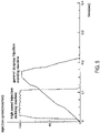
- liquid crystalline fully aromatic polyester has low melt viscosity and high solidification speed in molding, there is possibility where resin is solidified in a thin portion without providing sufficient fluidity in a case of an ultrathin article below 0.2 mm. Due to this, as molding is impossible or difficult with a general-purpose injection molding machine, it is preferable to conduct injection molding using a high-speed injection molding machine that has a property of enabling injection speed to attain its peak within 0.1 sec. as shown in Fig. 5 .
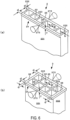
- FIG. 6 (a) is an isometric projection view showing a main portion of an insulating member for a slot coil of a second embodiment of the present disclosure.
- an insulating member 2 of the second embodiment there is no lug part flanges 16, 16 in the insulating member 1 of the first embodiment and gates 173, 173 are disposed at different positions.
- Number and shape of through-holes 23 are same as in the insulating member 1.
- thickness (a, b, c) of peripheral walls 231 and partition walls 233 of the through-holes 23 are same and formed to be thin of 0.15 mm to 0.55 mm.
- flanges 24 are formed on outer periphery at the upper end of the through-holes 23.
- the flanges 24 are made up of two flanges 25, 25 on long side disposed to be parallel to each other.
- the flanges 25, 25 on the long side are formed on the two long sides along whole length thereof.
- Thickness d of the flanges 25, 25 on the long side and height f of the flanges 25, 25 on the long side are formed to be larger than respective thickness a, b, c of the peripheral walls 231, 232 and the partition walls 233 (for example to be 1 mm).
- the flanges 24 serve as an aligning stopper when the insulating member 2 is fitted into the slot 101 shown in Fig.1 and also enable preventing varnish for electrically insulating the wire 11 and fixing thereof from leaking. Further, after molding of the insulating member 2, it is not necessary to cut off the flanges 24.
- Thermoplastic synthetic resin injected through a nozzle of an injection molding machine flows through pin side gates 273, 273 into the flanges 25, 25 on the long side respectively.
- These pin side gates 273, 273 are pin point gates provided at a central position in the lengthwise direction of the flanges 25, 25 on the long side and connected to the flanges 25, 25 on the long sides at a small point respectively.
- a direction in which thermoplastic synthetic resin flows through the pin side gates 273, 273 into the flanges 25, 25 on the long side is a direction of thickness of the flanges 25, 25 on the long side.
- thermoplastic synthetic resin having flowed through the pin side gates 273, 273 into the flanges 25, 25 on the long side collides with confronting walls (not shown) of the flanges 25, 25 on the long side to convert direction of flow thereof by 90°, causing flow-in velocity thereof to decrease and filling the flanges 25, 25 on the long side with it.
- thermoplastic synthetic resin flows into the thin outer peripheral walls 231, 232 and partition walls 233 at an optimum flow-in velocity thermoplastic synthetic resin flows smoothly, thus making it possible to form a smooth molded article. That is, as the flanges 25, 25 on the long side serve as runners, thermoplastic synthetic resin flows smoothly into the thin outer peripheral walls 231, 232 and the partition walls 233.
- FIG. 6, (b) is an isometric projection view showing a main portion of an insulating member for a slot coil of a third embodiment of the present disclosure.
- An insulating member 3 for a slot coil of the third embodiment of the present disclosure is distinctive in that number of through-holes is different from number of through-holes 23 of the insulating member 2 of the second embodiment, and in that flanges on the short side are added in the third embodiment. That is, with the insulating member 3 of the third embodiment, eight through-holes 33 are formed to be in two rows.
- outer peripheral walls 331, 332 and partition walls 133 of through-holes 33 are formed to have a same thickness (a, b, c), being thin as of 0.15 mm to 0.55, though not shown in section.
- flanges 34 are formed on outer periphery at the upper end of the through-holes 33.
- the flanges 34 are made up of two flanges 35, 35 on the long side and two flanges 38, 38 on the short side.
- the flanges 35, 35 on the long side are formed on the two long sides along whole length thereof respectively and the flanges 38, 38 on the short side are formed on the two short sides along whole length thereof respectively.
- Thickness d of the flanges 35, 35 on the long side and the flanges 38, 38 on the short side, and height f of the flanges 35, 35 on the long side and the flanges 38, 38 on the short side are larger than thickness a, b, c of the outer peripheral walls 331, 332 and the partition walls 333 (for example to be 1 mm).
- the flanges 34 serve as an aligning stopper when the insulating member 3 is fitted into the slot 101 shown in Fig. 1 and also enable preventing varnish from leaking. Further, after molding of the insulating member 3, it is not necessary to cut off the flanges 24.
- Thermoplastic synthetic resin injected through a nozzle of an injection molding machine flows through pin side gates 373, 373 into the flanges 35, 35 on the long side respectively.
- the pin side gates 373, 373 are pin point gates provided at a central position in the lengthwise direction of the flanges 35, 35 on the long side and connected to the flanges 35, 35 on the long sides at a small point respectively.
- a direction in which thermoplastic synthetic resin flows through the pin side gates 373, 373 into the flanges 35, 35 on the long side is a direction of thickness of the flanges 35, 35 on the long side.
- thermoplastic synthetic resin having flowed through the pin side gates 373, 373 into the flanges 35, 35 on the long side collides with confronting walls (not shown) of the flanges 35, 35 on the long side to convert direction of flow thereof by 90°, causing flow-in velocity thereof to decrease and filling the flanges 35, 35 on the long side and the flanges 38, 38 on the short side with it.
- thermoplastic synthetic resin flows into the thin outer peripheral walls 331, 332 and partition walls 333 at an optimum flow-in velocity thermoplastic synthetic resin flows smoothly, thus making it possible to form a smooth molded article. That is, as the flanges 35, 35 on the long side and the flanges 38, 38 on the short side serve as runners, thermoplastic synthetic resin flows smoothly into the thin outer peripheral walls 331, 332 and the partition walls 333.
- FIG. 7 is an isometric projection view showing a main portion of an insulating member for a slot coil of a fourth embodiment of the present disclosure.
- An insulating member 4 for a slot coil of the fourth embodiment of the present disclosure is distinctive in that shape of through-holes is different from shape of through-holes 13 of the insulating member 1 of the first embodiment, and in that a flange on the short side is added. That is, with the insulating member 4 of the fourth embodiment, shape of through-holes 43 is rectangular and number of through-holes 43 is six in a same manner.
- outer peripheral walls 431, 432 and partition walls 433 of through-holes 33 have a same thickness (a, b, c) and formed to be thin as of 0.15 mm to 0.55 mm, though not shown in section.
- flanges 44 are formed on outer periphery at the upper end of the through-holes 43.
- the flanges 44 are made up of two flanges 45, 45 on the long side, two lug part flanges 46, 46 and a flange 48 on the short side.
- the flanges 45, 45 on the long side are formed on the two long sides along whole length thereof respectively and the lug part flanges 46, 46 are formed at one end of the flanges 45, 55 on the long side to protrude from the respective flanges 45, 45 on the long side. Further, the flange 48 on the short side is formed on the other end of the flanges 45, 55 on the long side along whole length of the short side.
- Thickness d of the flanges 45, 45 on the long side and the flange 48 on the short side, thickness e of the lug part flange 46, 46 and height f of the flanges 45, 45 on the long side, the flanges 48 on the short side and the lug part flanges 46, 46 are formed to be larger than thickness a, b, c of the outer peripheral walls 431, 432 and the partition walls 433 (for example to be 1 mm).
- the flanges 44 serve as an aligning stopper when the insulating member 4 is fitted into the slot 101 shown in Fig.1 and also enable preventing varnish from leaking. Further, after molding of the insulating member 4, it is not necessary to cut off the flanges 44.
- Thermoplastic synthetic resin injected from a nozzle of an injection molding machine flows through gates 473, 473 into the lug part flanges 46, 46 respectively.
- the gates 473, 473 are pinpoint gates connected to the lug part flanges 16, 16 at small points respectively.
- Direction of thermoplastic synthetic resin flowing through the gates 473, 473 into the lug part flanges 46, 46 is a direction of thickness of the lug part flanges 46, 46.
- thermoplastic synthetic resin having flowed through the gates 473, 473 into the lug part flanges 46, 46 collides with confronting walls (not shown) of the lug part flanges 46, 46 to convert direction of flow thereof by 90° and causes flow-in velocity thereof to decrease, filling the lug part flanges 46, 46, the flanges 45, 45 on the long side and the flange 48 on the short side.
- thermoplastic synthetic resin flows into the thin outer peripheral walls 431, 432 and partition walls 433 at an optimum flow-in velocity thermoplastic synthetic resin flows smoothly into the thin outer peripheral walls 431, 432 and partition walls 433.
- the short side is longer than the insulating member 1 of the first embodiment, so that the flange 48 on the short side serve as runner effectively.
- FIG. 7, (b) is an isometric projection view showing a main portion of an insulating member for a slot coil of a fifth embodiment of the present disclosure.
- An insulating member 5 for a slot coil of the fifth embodiment of the present disclosure is distinctive in that number of through-holes is different from number of through-holes 23 of the insulating member 2 of the second embodiment, and in that a flange on the short side is added and position of flow-in through a gate is different. That is, with the insulating member 5 of the fifth embodiment, four through-holes 53 are formed to be in a row.
- outer peripheral walls 531, 532 and partition walls 533 of through-holes 53 are formed to have a same thickness (a, b, c), being formed to be thin as of 0.15 mm to 0.55, though not shown in section.
- flanges 54 are formed on outer periphery at the upper end of the through-holes 53.
- the flanges 54 are made up of two flanges 55, 55 on the long side and a flange 58 on the short side.
- the flanges 55, 55 on the long side are formed on the two long sides along whole length thereof respectively and the flange 58 on the short side is formed on a short side along whole length thereof.
- Thickness d of the flanges 55, 55 on the long side and the flange 58 on the short side, and height f of the flanges 55, 55 on the long side and the flange 58 on the short side are larger than thickness a, b, c of the outer peripheral walls 531, 532 and the partition walls 533 (for example to be 1 mm).
- the flanges 54 serve as an aligning stopper when the insulating member 5 is fitted into the slot 101 shown in Fig. 1 and also enable preventing varnish from leaking. Further, after molding of the insulating member 5, it is not necessary to cut off the flanges 54.
- Thermoplastic synthetic resin injected through a nozzle of an injection molding machine flows through a pin side gate 573 into the flange 58 on the short side.
- the pin side gates 573 is a pin point gate provided at a central position in the lengthwise direction of the flange 58 on the short side and connected to the flange 58 on the short side at a small point.
- a direction in which thermoplastic synthetic resin flows through the pin side gates 573 into the flanges 58 on the short side is a direction of thickness of the flange 58 on the short side.
- thermoplastic synthetic resin having flowed through the pin side gate 573 into the flange 58 on the short side collides with confronting walls (not shown) of the flange 58 on the short side to convert direction of flow thereof by 90°, causing flow-in velocity thereof to decrease and filling the flange 58 on the short side and the flanges 55, 55 on the long side.
- thermoplastic synthetic resin flows into the thin outer peripheral walls 531, 532 and partition walls 533 at an optimum flow-in velocity thermoplastic synthetic resin flows smoothly, thus making it possible to form a smooth molded article. That is, as the flanges 58 on the short side and the flanges 55, 55 on the long side serve as runners, thermoplastic synthetic resin flows smoothly into the thin outer peripheral walls 531, 532 and the partition walls 533.
- FIG. 8 (a) is an isometric projection view showing a main portion of an insulating member for a slot coil of a sixth embodiment of the present disclosure.
- An insulating member 6 for a slot coil of the sixth embodiment of the present disclosure is distinctive in that number and shape of through-holes are different from those of through-holes 13 of the insulating member 1 of the first embodiment.
- the insulating member 6 of the sixth embodiment has one through-hole 63 of a rectangular shape of a large area. With the insulating member 6, outer peripheral walls 631, 632 of the through-hole 63 has a same thickness (a (not shown), b) formed thin to be as of 0.15 to 0.55 mm.
- flanges 64 are formed on outer periphery at the upper end of the through-hole 63.
- the flanges 64 are made up of two flanges 65, 65 on the long side and two lug part flanges 66, 66.
- the flanges 65, 65 on the long side are formed on the two long sides along whole length thereof respectively and the lug part flanges 66, 66 are formed at one end of the flanges 65, 65 on the long side to protrude with a right angle from the respective flanges 65, 65 on the long side.
- Thickness d of the flanges 65, 65 on the long side, thickness e of the lug part flanges 66, 66 and height f of the flanges 65, 65 on the long side and the lug part flanges 66, 66 are formed to be larger than thickness a, b of the outer peripheral walls 631, 632 (for example to be 1 mm).
- the flanges 64 serve as an aligning stopper when the insulating member 6 is fitted into the slot 101 shown in Fig.1 and also enable preventing varnish from leaking. Further, after molding of the insulating member 6, it is not necessary to cut off the flanges 64.
- Thermoplastic synthetic resin injected from a nozzle of an injection molding machine flows through gates 673, 673 into the lug part flanges 66, 66 respectively.
- the gates 673, 673 are pin point gates connected to the lug part flanges 66, 66 at small points respectively.
- Direction of thermoplastic synthetic resin flowing through the gates 673, 673 into the lug part flanges 66, 66 is a direction of thickness of the lug part flanges 66, 66.
- thermoplastic synthetic resin having flowed through the gates 673, 673 into the lug part flanges 66, 66 collides with confronting walls (not shown) of the lug part flanges 66, 66 to convert direction of flow thereof by 90° and causes flow-in velocity thereof to decrease, filling the lug part flanges 66, 66 and the flanges 65, 65 on the long side.
- thermoplastic synthetic resin flows into the thin outer peripheral walls 631, 632 at an optimum flow-in velocity thermoplastic synthetic resin flows smoothly, thus making it possible to form a smooth molded article. That is, as the lug part flanges 66, 66 and the flanges 65, 65 on the long side serve as runners, thermoplastic synthetic resin flows smoothly into the thin outer peripheral walls 631, 632.
- FIG. 8 is an isometric projection view showing a main portion of an insulating member for a slot coil of a seventh embodiment of the present disclosure.
- An insulating member 7 for a slot coil of the seventh embodiment of the present disclosure has not the flanges 65, 65 on the long side and the lug part flanges 66, 66 of the insulating member 6 of the sixth embodiment of the present disclosure provided, but has a flange on the short side provided. That is, with the insulating member 7, outer peripheral walls 731, 732 around the through-hole 73 has a same thickness (a, b) formed thin to be as of 0.15 to 0.55 mm.
- a flange 74 is formed on outer periphery at the upper end of the through-hole 73.
- the flange 74 is made up of one flange 78 on the short side. Thickness d of the flange 78 on the short side and height f of the flange 78 on the short side are formed to be larger than thickness a, b of the outer peripheral walls 731, 732 (for example to be 1 mm).
- This flange 74 serves as an aligning stopper when the insulating member 7 is fitted into the slot 101 shown in Fig.1 and also enable preventing varnish from leaking. Further, after molding of the insulating member 7, it is not necessary to cut off the flange 74.
- Thermoplastic synthetic resin injected from a nozzle of an injection molding machine flows through a pin side gate 773 into the flange 78 on the short side.
- the pin side gate 773 is a pin point gate provided at a central position of the flange 78 on the short side in lengthwise direction thereof and connected thereto at a small point.
- Direction of thermoplastic synthetic resin flowing through the gates 773 into the flange 78 on the short side is a direction of thickness of the flanges 78 on the short side.
- thermoplastic synthetic resin having flowed through the gates 773 into the flange 78 on the short side collides with a confronting wall (not shown) of the flange 78 on the short side to convert direction of flow thereof by 90° and causes flow-in velocity thereof to decrease, filling the flange 78 on the short side.
- thermoplastic synthetic resin flows into the thin outer peripheral walls 731, 732 at an optimum flow-in velocity thermoplastic synthetic resin flows smoothly, thus making it possible to form a smooth molded article. That is, as the flange 78 on the short side serves as a runner, thermoplastic synthetic resin flows smoothly into the thin outer peripheral walls 731, 732.
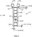
- Fig. 9 is a plan view showing an insulating member 1' for a slot coil of an eighth embodiment of the present disclosure.
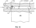
- Fig. 10 is a partial enlarged view of Fig. 9 as seen in a direction of an arrow A.
- the insulating member 1' for a slot coil of the eighth embodiment is analogous to the insulating member 1 for a slot coil of the first embodiment shown in Figs 2 to 4 in shape and a method for molding thereof.
- the insulating member 1 for a slot coil of the first embodiment has long and thin (for example no more than 0.3 mm) outer peripheral walls 131, 132 and partition walls 133, such a situation may occur that injected resin does not flow fully through cavity of the metallic mold.
- the insulating member 1' for a slot coil of the eighth embodiment has a structure with which flow of injected resin is improved.
- the insulating member 1' for a slot coil of the eighth embodiment will be explained only for portions different from those of the first embodiment, omitting explanation of portions of same shape and arrangement below.
- a molten resin basin 135 extended from the flange 15 on the long side is formed at an end of each of the flanges 15 on the long side.
- the molten resin basins 135 are extended from the flanges 15 on the long side by about 1.0 to 1. 5 mm in this embodiment.
- the gate in this embodiment 173a has a pyramid form with a rectangular cross section and preferably has an inclination angle ⁇ preferably of about 30° (see Fig. 10 ).
- molten resin can flow smoothly. Injected molten resin is squeezed through the gate 173a to generate friction heat, raising temperature of molten resin to lower its viscosity, thus flowing to lug part flanges 16. Molten resin flowing to the lug part flanges 16 further flows into the flanges 15, 15 on the long side, converting direction of flow by 90° (see Fig. 3, (b) ).
- molten resin flowing to the lug part flanges 16 further flows into the flanges 15 on the long side, converting direction of flow by 90°. Height of the lug part flanges 16 is lower than the flanges 15 on the long side by S mm. That is, molten resin discharged from the gates 173a flows to the lug part flanges 16 having a cross section of flow path narrower than the flanges 15 on the long side. Then, molten resin flows into the flanges 15 on the long side after converting direction of flow twice each by 90°. As molten resin flows into the flanges 15 on the long side through the 16 having a cross section of flow path narrower than the flanges 15 on the long side, the lug part flanges 16 serve for restraining flow of resin.
- molten resin basins 135 are formed at the end of the long side flanges 135 on the long side opposite to the gates 173a, flow of injected molten resin into the thin outer peripheral walls 131, 132 and partition walls 133 is induced after it has filled the long side flanges 135 on the long side and the molten resin basins 135.
- the outer peripheral walls 131, 132 and the partition walls 133 are long (downwards in Fig. 10 )
- molten resin flows evenly and smoothly into the outer peripheral walls 131, 132 and the partition walls 133, as the molten resin basins 135 are formed opposite to the lug part flanges 16, the long side flanges 15, and the gates 173a.
- Fig. 11 (a) is an isometric projection view showing of an insulating member 2' for a slot coil of a ninth embodiment of the present disclosure, and in Fig. 11, (b) is a partial sectional view of (a) in Fig. 11 taken along a line B-B.
- the insulating member 2' for a slot coil of the ninth embodiment is analogous to the insulating member 2 for a slot coil of the second embodiment shown in Fig. 6 , in shape and a method for molding thereof.
- the insulating member 2' for a slot coil of the second embodiment has long and thin outer peripheral walls 231, 232 and partition walls 233, such a situation may occur that injected resin does not flow fully through cavity of the metallic mold.
- the insulating member 2' for a slot coil of the ninth embodiment has a structure with which flow of injected resin is improved.
- the insulating member 2' for a slot coil of the ninth embodiment will be explained only for portions different from those of the second embodiment, omitting explanation of portions of same shape and arrangement below.
- Molding of the insulating member 2' of the ninth embodiment of the present disclosure is an example using a fan gate(s) (fan shaped) 873 in molding thereof.
- the fan gate is a thin (shallow), film-shaped and thin (shallow) gate(s) with a large width having a length same as a width of the flange 25 on the long side of the insulating member 2'.
- This is also an example in which fan gates 873 are disposed on the both sides of the flanges 25 on the long side.
- the fan gates 873 has function with which molten resin flows almost parallel to the flanges 25 on the long side and fills the flanges 25 on the long side evenly, thus preventing drift, etc.
- the fan gates 873 are used for resin such as crystalline resin with which drift occurs easily.
- resin flows fast at the center position of the fan gates 873 especially if pressure of injection molding is high.
- cylindrical pins 875 are disposed in a metallic mold for injection molding (not shown) in this embodiment. With the cylindrical pins 875 disposed, it is possible to create turbulent flow in molten resin flowing through runners 874 to the fan gates 873 and to restrain the molten resin flowing into central portion of the flanges 25 on the long side, thus causing molten resin flowing into the flanges 25 to be even.
- Fig. 12 (a) is an isometric projection view showing an insulating member 2" for a slot coil of a tenth embodiment of the present disclosure, and in Fig. 12, (b) is a partial sectional view of (a) in Fig. 12 taken along a line B-B.
- the insulating member 2" of the tenth embodiment is identical with the ninth embodiment in using fan gates 873 for injection molding thereof. Injection molding of the insulating member 2" of the tenth embodiment is different from that of the ninth embodiment in causing molten resin to flow from fan gates 873 through molten resin basins 876 and film-shaped film runners 877 into the flanges 25 respectively in the tenth embodiment.
- the molten resin basins 876 can be said to be a kind of mini runners. As flow of molten resin from the fan gates 873 becomes turbulent because it is squeezed, flow is stabilized by changing dynamic pressure to static pressure in the molten resin basins 876. Molten resin stabilized in the molten resin basins 876 becomes laminar flow in the film runner 877 having flow path with even cross section to flow into the flanges 25 on the long side. As understood from this explanation, molten resin flows smoothly into the outer peripheral walls 231, 232 for the insulating member 2" molded by the method of the tenth embodiment, so that an insulating member 2" having long outer peripheral walls also can be molded.
- the gates 173a of the eighth embodiment explained above are ones as so-called side gates, angle at which these gates are disposed may be changed with 90°, according to a structure of a metallic mold for injection molding. Even in this case, such structure is preferable that molten resin flows into the flanges 15 on the long side converting direction of flow each by 90° twice.
- the insulating members 1 to 7 of the embodiments explained above have been explained as ones for a stator of a rotary electric machine. However, the insulating members 1 to 7 may be used also for rotors.
- the control pins 876 in the ninth embodiment explained above have a circular cross section, they are not limited to have such a shape. As the control pins 876 are disposed so as to cause flow of resin evenly and are a kind of member for flow control inhibiting or delaying flow of injected molten resin, they may have other shapes of cross section as long as they provide this function.
Landscapes
- Engineering & Computer Science (AREA)
- Manufacturing & Machinery (AREA)
- Power Engineering (AREA)
- Mechanical Engineering (AREA)
- Insulation, Fastening Of Motor, Generator Windings (AREA)
- Moulds For Moulding Plastics Or The Like (AREA)
- Injection Moulding Of Plastics Or The Like (AREA)
- Manufacture Of Motors, Generators (AREA)
- Windings For Motors And Generators (AREA)
Applications Claiming Priority (2)
| Application Number | Priority Date | Filing Date | Title |
|---|---|---|---|
| JP2020077333A JP2022010425A (ja) | 2020-04-24 | 2020-04-24 | 回転電機のスロットコイル用絶縁材とその成形方法 |
| PCT/JP2021/016218 WO2021215482A1 (fr) | 2020-04-24 | 2021-04-21 | Matériau isolant pour bobine à fente d'une machine rotative et son procédé de moulage |
Publications (2)
| Publication Number | Publication Date |
|---|---|
| EP4140689A1 true EP4140689A1 (fr) | 2023-03-01 |
| EP4140689A4 EP4140689A4 (fr) | 2024-05-08 |
Family
ID=78269196
Family Applications (1)
| Application Number | Title | Priority Date | Filing Date |
|---|---|---|---|
| EP21791882.0A Withdrawn EP4140689A4 (fr) | 2020-04-24 | 2021-04-21 | Matériau isolant pour bobine à fente d'une machine rotative et son procédé de moulage |
Country Status (6)
| Country | Link |
|---|---|
| US (1) | US12407207B2 (fr) |
| EP (1) | EP4140689A4 (fr) |
| JP (2) | JP2022010425A (fr) |
| KR (1) | KR20230035521A (fr) |
| CN (1) | CN115668699A (fr) |
| WO (1) | WO2021215482A1 (fr) |
Families Citing this family (4)
| Publication number | Priority date | Publication date | Assignee | Title |
|---|---|---|---|---|
| JP7763673B2 (ja) * | 2022-01-20 | 2025-11-04 | 株式会社日立産機システム | 回転電機および産業機械 |
| CN120077554A (zh) * | 2022-10-13 | 2025-05-30 | Lg麦格纳电子动力总成有限公司 | 旋转电机的定子及其制造方法 |
| JP2024157333A (ja) * | 2023-04-25 | 2024-11-07 | トヨタ紡織株式会社 | ロータ及びロータの製造方法 |
| EP4501577A1 (fr) * | 2023-07-29 | 2025-02-05 | ABB Schweiz AG | Procédé de fabrication d'un isolateur moyenne tension moulé par injection et isolateur moyenne tension |
Family Cites Families (13)
| Publication number | Priority date | Publication date | Assignee | Title |
|---|---|---|---|---|
| SK279172B6 (sk) * | 1990-07-03 | 1998-07-08 | �Kd Trakce | Izolačný systém vinutia elektrického stroja |
| JPH07205264A (ja) * | 1994-01-11 | 1995-08-08 | Nippon Steel Chem Co Ltd | 多層ブロー成形品 |
| JP2003070201A (ja) * | 2001-08-23 | 2003-03-07 | Toyota Motor Corp | 回転電機のステータおよびその製造方法 |
| JP4797728B2 (ja) * | 2006-03-22 | 2011-10-19 | トヨタ自動車株式会社 | 回転電機の固定子、固定子に用いられる部品および回転電機の固定子の製造方法 |
| JP4878002B2 (ja) | 2006-07-06 | 2012-02-15 | 株式会社日本自動車部品総合研究所 | 電磁機器 |
| JP5731831B2 (ja) * | 2011-01-18 | 2015-06-10 | 本田技研工業株式会社 | 鋳造用金型 |
| JP5971125B2 (ja) * | 2013-01-09 | 2016-08-17 | 株式会社デンソー | 固定子及びそれを備えた回転電機 |
| EP2824801A1 (fr) * | 2013-07-12 | 2015-01-14 | Siemens Aktiengesellschaft | Procédé de fabrication d'une machine rotative dynamoélectrique et machine rotative dynamoélectrique |
| WO2017047247A1 (fr) * | 2015-09-17 | 2017-03-23 | 日立オートモティブシステムズ株式会社 | Machine électrique tournante |
| JP6833532B2 (ja) | 2017-01-30 | 2021-02-24 | 本田技研工業株式会社 | スロットコイル、回転電機のステータ、及び回転電機のステータの製造方法 |
| DE102017220123A1 (de) * | 2017-11-13 | 2019-05-16 | Audi Ag | Nutwandisolation für einen Stator eines Elektromotors |
| JP7262926B2 (ja) | 2018-03-16 | 2023-04-24 | 株式会社日立製作所 | ラジアルギャップ型回転電機 |
| JP6709870B2 (ja) * | 2019-04-09 | 2020-06-17 | 本田技研工業株式会社 | 電動機用ステータの製造方法および電動機用ステータ |
-
2020
- 2020-04-24 JP JP2020077333A patent/JP2022010425A/ja active Pending
-
2021
- 2021-04-21 WO PCT/JP2021/016218 patent/WO2021215482A1/fr not_active Ceased
- 2021-04-21 EP EP21791882.0A patent/EP4140689A4/fr not_active Withdrawn
- 2021-04-21 JP JP2021578271A patent/JP7103704B2/ja active Active
- 2021-04-21 KR KR1020227041314A patent/KR20230035521A/ko active Pending
- 2021-04-21 US US17/920,804 patent/US12407207B2/en active Active
- 2021-04-21 CN CN202180039297.0A patent/CN115668699A/zh active Pending
Also Published As
| Publication number | Publication date |
|---|---|
| CN115668699A (zh) | 2023-01-31 |
| US12407207B2 (en) | 2025-09-02 |
| KR20230035521A (ko) | 2023-03-14 |
| JPWO2021215482A1 (fr) | 2021-10-28 |
| JP2022010425A (ja) | 2022-01-17 |
| WO2021215482A1 (fr) | 2021-10-28 |
| JP7103704B2 (ja) | 2022-07-20 |
| US20230208235A1 (en) | 2023-06-29 |
| EP4140689A4 (fr) | 2024-05-08 |
Similar Documents
| Publication | Publication Date | Title |
|---|---|---|
| EP4140689A1 (fr) | Matériau isolant pour bobine à fente d'une machine rotative et son procédé de moulage | |
| CA1070072A (fr) | Moule chauffant | |
| JP4886102B2 (ja) | 部品間のギャップを無接触でシールする装置 | |
| US10587175B2 (en) | Double-stator rotating electric machine | |
| US11322997B2 (en) | Rotor for a synchronous drive motor | |
| JP2023517893A (ja) | 新エネルギー車用の駆動モータの冷却システム | |
| JPWO2021215482A5 (fr) | ||
| DE19854464C2 (de) | Flüssigkeitsgekühlter Generator | |
| JP5811350B2 (ja) | ローターの製造方法 | |
| US4647807A (en) | Rotating collector assembly for electrical machines | |
| JP6869304B2 (ja) | インサート成形品および、インサート成形品の製造方法 | |
| CN111226381A (zh) | 具有注入保持架的转子 | |
| JP7521155B2 (ja) | 回転電機のコアと導線の絶縁材の組立方法 | |
| US12068647B2 (en) | Coil module for an electric machine | |
| US7393489B2 (en) | Mold die for molding chip array, molding equipment including the same, and method for molding chip array | |
| JP7698285B2 (ja) | 回転電機のスロットコイル用絶縁体の成形方法 | |
| CN223487951U (zh) | 转子组件、电机及电器设备 | |
| AU2022264829A1 (en) | Coil module for an electric machine | |
| CN217789424U (zh) | 一种永磁同步电机转子铁芯 | |
| CN108422834B (zh) | 一种在高风压下防啸叫的汽车自闭出风口 | |
| CN217144746U (zh) | 一种汽车零件注塑模具 | |
| CN1327520C (zh) | 具有静电放电防护的封装基板 | |
| KR940001269Y1 (ko) | 팩키지 몰딩용 다이 | |
| WO2025204327A1 (fr) | Échangeur de chaleur de refroidissement | |
| JP6735782B2 (ja) | モータのバスリング構造 |
Legal Events
| Date | Code | Title | Description |
|---|---|---|---|
| STAA | Information on the status of an ep patent application or granted ep patent |
Free format text: STATUS: THE INTERNATIONAL PUBLICATION HAS BEEN MADE |
|
| PUAI | Public reference made under article 153(3) epc to a published international application that has entered the european phase |
Free format text: ORIGINAL CODE: 0009012 |
|
| STAA | Information on the status of an ep patent application or granted ep patent |
Free format text: STATUS: REQUEST FOR EXAMINATION WAS MADE |
|
| 17P | Request for examination filed |
Effective date: 20221116 |
|
| AK | Designated contracting states |
Kind code of ref document: A1 Designated state(s): AL AT BE BG CH CY CZ DE DK EE ES FI FR GB GR HR HU IE IS IT LI LT LU LV MC MK MT NL NO PL PT RO RS SE SI SK SM TR |
|
| DAV | Request for validation of the european patent (deleted) | ||
| DAX | Request for extension of the european patent (deleted) | ||
| A4 | Supplementary search report drawn up and despatched |
Effective date: 20240409 |
|
| RIC1 | Information provided on ipc code assigned before grant |
Ipc: H02K 3/30 20060101ALN20240403BHEP Ipc: H02K 15/10 20060101ALI20240403BHEP Ipc: B29C 45/26 20060101ALI20240403BHEP Ipc: H02K 15/085 20060101ALI20240403BHEP Ipc: H02K 15/02 20060101ALI20240403BHEP Ipc: H02K 3/34 20060101ALI20240403BHEP Ipc: H02K 3/04 20060101ALI20240403BHEP Ipc: B29C 45/38 20060101ALI20240403BHEP Ipc: B29C 45/00 20060101AFI20240403BHEP |
|
| STAA | Information on the status of an ep patent application or granted ep patent |
Free format text: STATUS: THE APPLICATION IS DEEMED TO BE WITHDRAWN |
|
| 18D | Application deemed to be withdrawn |
Effective date: 20241029 |