EP4142146B1 - Système d'entraînement - Google Patents
Système d'entraînement Download PDFInfo
- Publication number
- EP4142146B1 EP4142146B1 EP22186135.4A EP22186135A EP4142146B1 EP 4142146 B1 EP4142146 B1 EP 4142146B1 EP 22186135 A EP22186135 A EP 22186135A EP 4142146 B1 EP4142146 B1 EP 4142146B1
- Authority
- EP
- European Patent Office
- Prior art keywords
- motor
- bridge
- current
- measuring resistor
- drive system
- Prior art date
- Legal status (The legal status is an assumption and is not a legal conclusion. Google has not performed a legal analysis and makes no representation as to the accuracy of the status listed.)
- Active
Links
Images
Classifications
-
- H—ELECTRICITY
- H02—GENERATION; CONVERSION OR DISTRIBUTION OF ELECTRIC POWER
- H02P—CONTROL OR REGULATION OF ELECTRIC MOTORS, ELECTRIC GENERATORS OR DYNAMO-ELECTRIC CONVERTERS; CONTROLLING TRANSFORMERS, REACTORS OR CHOKE COILS
- H02P29/00—Arrangements for regulating or controlling electric motors, appropriate for both AC and DC motors
- H02P29/60—Controlling or determining the temperature of the motor or of the drive
-
- H—ELECTRICITY
- H02—GENERATION; CONVERSION OR DISTRIBUTION OF ELECTRIC POWER
- H02P—CONTROL OR REGULATION OF ELECTRIC MOTORS, ELECTRIC GENERATORS OR DYNAMO-ELECTRIC CONVERTERS; CONTROLLING TRANSFORMERS, REACTORS OR CHOKE COILS
- H02P27/00—Arrangements or methods for the control of AC motors characterised by the kind of supply voltage
- H02P27/04—Arrangements or methods for the control of AC motors characterised by the kind of supply voltage using variable-frequency supply voltage, e.g. inverter or converter supply voltage
- H02P27/06—Arrangements or methods for the control of AC motors characterised by the kind of supply voltage using variable-frequency supply voltage, e.g. inverter or converter supply voltage using DC to AC converters or inverters
- H02P27/08—Arrangements or methods for the control of AC motors characterised by the kind of supply voltage using variable-frequency supply voltage, e.g. inverter or converter supply voltage using DC to AC converters or inverters with pulse width modulation
-
- H—ELECTRICITY
- H02—GENERATION; CONVERSION OR DISTRIBUTION OF ELECTRIC POWER
- H02P—CONTROL OR REGULATION OF ELECTRIC MOTORS, ELECTRIC GENERATORS OR DYNAMO-ELECTRIC CONVERTERS; CONTROLLING TRANSFORMERS, REACTORS OR CHOKE COILS
- H02P29/00—Arrangements for regulating or controlling electric motors, appropriate for both AC and DC motors
- H02P29/02—Providing protection against overload without automatic interruption of supply
- H02P29/024—Detecting a fault condition, e.g. short circuit, locked rotor, open circuit or loss of load
- H02P29/027—Detecting a fault condition, e.g. short circuit, locked rotor, open circuit or loss of load the fault being an over-current
-
- H—ELECTRICITY
- H02—GENERATION; CONVERSION OR DISTRIBUTION OF ELECTRIC POWER
- H02P—CONTROL OR REGULATION OF ELECTRIC MOTORS, ELECTRIC GENERATORS OR DYNAMO-ELECTRIC CONVERTERS; CONTROLLING TRANSFORMERS, REACTORS OR CHOKE COILS
- H02P5/00—Arrangements specially adapted for regulating or controlling the speed or torque of two or more electric motors
- H02P5/74—Arrangements specially adapted for regulating or controlling the speed or torque of two or more electric motors controlling two or more AC dynamo-electric motors
-
- H—ELECTRICITY
- H02—GENERATION; CONVERSION OR DISTRIBUTION OF ELECTRIC POWER
- H02P—CONTROL OR REGULATION OF ELECTRIC MOTORS, ELECTRIC GENERATORS OR DYNAMO-ELECTRIC CONVERTERS; CONTROLLING TRANSFORMERS, REACTORS OR CHOKE COILS
- H02P6/00—Arrangements for controlling synchronous motors or other dynamo-electric motors using electronic commutation dependent on the rotor position; Electronic commutators therefor
- H02P6/08—Arrangements for controlling the speed or torque of a single motor
- H02P6/085—Arrangements for controlling the speed or torque of a single motor in a bridge configuration
-
- H—ELECTRICITY
- H02—GENERATION; CONVERSION OR DISTRIBUTION OF ELECTRIC POWER
- H02P—CONTROL OR REGULATION OF ELECTRIC MOTORS, ELECTRIC GENERATORS OR DYNAMO-ELECTRIC CONVERTERS; CONTROLLING TRANSFORMERS, REACTORS OR CHOKE COILS
- H02P7/00—Arrangements for regulating or controlling the speed or torque of electric DC motors
- H02P7/03—Arrangements for regulating or controlling the speed or torque of electric DC motors for controlling the direction of rotation of DC motors
- H02P7/04—Arrangements for regulating or controlling the speed or torque of electric DC motors for controlling the direction of rotation of DC motors by means of a H-bridge circuit
Definitions
- the invention relates to a drive system according to the preamble of patent claim 1 and to a household appliance with such a drive system according to patent claim 9.
- Synchronous motors which can be operated with single-phase alternating current, are also among the well-known electric motors.
- a constantly magnetized rotor is used, which can also be referred to as a rotor. Permanent magnets or external electromagnetic excitation can be used for this.
- the term synchronous motor comes from the fact that the rotor is driven synchronously by a moving magnetic rotating field in the stator. Thus, during operation, the synchronous motor exhibits a movement synchronous to the alternating voltage, and its speed is linked to the frequency of the alternating voltage via the number of pole pairs in the synchronous motor's stator.
- Multi-phase permanent magnet synchronous motors are typically operated via a frequency converter, which enables controlled operation by specifying the direction of rotation, speed, and torque of the synchronous motor via the frequency and amplitude of the frequency converter's AC output voltage. This can specifically influence the rotational behavior of the synchronous motor, for example, during start-up or depending on the load being driven.
- uncontrolled single-phase synchronous motors are known to drive drain pumps, for example, in simple applications such as drain pumps in washing machines.
- Permanent-magnet single-phase synchronous motors are typically used in these applications, eliminating the need for electrical contact between the stator and the rotor via slip rings or brushes.
- permanent magnet single-phase synchronous motors that they have a synchronous voltage to the alternating voltage during operation. Perform a movement whose speed is linked to the frequency of the alternating voltage via the number of pole pairs in the stator. This makes it very easy to operate a permanent-magnet single-phase synchronous motor at the frequency of the mains alternating voltage, eliminating the need for costly controllers and frequency converters. Instead, a simple control of the single-phase synchronous motor via an H-bridge, which can be operated by a control unit, is sufficient. This is particularly beneficial for simple, uncontrolled applications with a constant speed, such as drain pumps in washing machines.
- a device uses at least one such single-phase synchronous motor or another single-phase AC motor that is not thermally intrinsically safe, i.e., which can be thermally overloaded by sufficiently high current
- thermal monitoring of the single-phase synchronous motor is required.
- Such thermal overload can occur, for example, due to a fault in the form of incorrect or excessively high current supply, for example, due to a short circuit in the electronics of the drive system to which the single-phase synchronous motor belongs.
- thermal overload of the single-phase synchronous motor is detected, it is shut down to prevent damage to the single-phase synchronous motor. Accordingly, such a single-phase synchronous motor must be monitored for overheating. This can be done by evaluating the motor currents to avoid additional temperature sensors and the associated costs, etc.
- a thermal monitoring system of this type is required for each single-phase synchronous motor. Accordingly, the additional thermal monitoring systems or the corresponding electronics can increase manufacturing costs in terms of materials and assembly effort, space requirements in the appliance or on the electronics, power consumption, and/or the generated waste heat.
- the invention therefore addresses the problem of providing a drive system of the type described above that can thermally monitor multiple single-phase AC motors with less electronic or circuitry complexity than previously known, particularly by evaluating the motor currents during operation. This should be possible in a more cost-effective, space-saving, energy-efficient manner, and/or with less waste heat. At the very least, an alternative to known drive systems of this type should be created.
- the invention relates to a drive system having at least one first motor, having at least one first H-bridge which is designed to operate the first motor, wherein the first H-bridge has a first half-bridge with a first measuring resistor and a second half-bridge with a second measuring resistor, and having a control unit which is designed to evaluate the currents of the first measuring resistor and the second measuring resistor with regard to a thermal load of the first motor.
- the drive system is characterized by at least one second motor and at least one second H-bridge, which is designed to operate the second motor, wherein the second H-bridge has the second half-bridge with the second measuring resistor and a third half-bridge with a third measuring resistor, wherein the control unit is further designed to evaluate the currents of the second measuring resistor and the third measuring resistor with regard to a thermal load on the second motor.
- This can accordingly reduce the circuitry complexity in order to thermally monitor two motors by means of current measurement, since the second measuring resistor of the second half-bridge can be used twice, so to speak. This can reduce the costs in terms of material and assembly as well as the space requirement, energy consumption and/or heat generation.
- control unit is designed to operate the first half-bridge, the second half-bridge, and the third half-bridge.
- the Effort etc. can be reduced by allowing all three half-bridges to be operated or controlled by a common control unit.
- the drive system comprises a rectifier configured to receive an AC voltage from a voltage input of the drive system and to provide a DC voltage to the first half-bridge, the second half-bridge, and the third half-bridge. This allows the drive system to be converted to an AC voltage.
- the drive system comprises a smoothing capacitor configured to smooth the DC voltage of the rectifier output. This allows for the reduction of residual ripple in the rectified AC voltage.
- the first motor and the second motor are single-phase AC motors, preferably single-phase synchronous motors. This may enable the implementation of the drive system with such motors.
- the present invention also relates to a household appliance, preferably a washing machine or a dishwasher, with at least one drive system as described above. This allows the properties and advantages of a drive system according to the invention to be implemented and utilized in a household appliance.
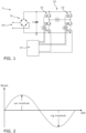
- the smoothed DC voltage is then applied in parallel to a first half-bridge 12 and a second half-bridge 13, which together form a first H-bridge 15.
- the first half-bridge 12 has a first power semiconductor T1, a second power semiconductor T2, a first driver D1, and a first measuring resistor R1 as the first shunt R1.
- the second half-bridge 13 has a third power semiconductor T3, a fourth power semiconductor T4, a second driver D2, and a second measuring resistor R2 as the second shunt R2.
- a first motor M1, which can be driven by the first H-bridge 15, is arranged between the two half-bridges 12, 13.
- a control unit 17 in the form of a computer 17 is connected via the two drivers D1, D2 to the four power semiconductors T1-T4.
- the two measuring resistors R1, R2 are also connected to the control unit 17, so that during operation, the currents in the first motor M1 are recorded and the first motor M1 can be controlled by the control unit 17 based on this, see Figure 1
- the first motor M1 is a single-phase AC motor or a single-phase synchronous motor, which can be used, for example, in a household appliance such as a washing machine or dishwasher as a circulation pump motor or as a drain pump motor.
- the first motor M1 is aligned with the direct current and then ramped up at an ever-increasing frequency until the first motor M1 is running in controlled operation.
- the speed of the first motor M1 can be adjusted by the control unit 17 via the frequency.
- the first motor M1 is not thermally intrinsically safe, i.e., if the full bus voltage of, for example, +300 V is applied to the first motor M1 in the event of a fault, the first motor M1 may overheat because the winding resistance is not very high. For this reason, the first motor M1 is thermally monitored by the control unit 17. This monitoring is based on the currents in the first motor M1, which are detected by the control unit 17 via the two measuring resistors R1, R2.
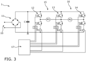
- the second motor M2 is operated with a second H-bridge 16 by the same control unit 17, wherein the second H-bridge 16 also uses the second half-bridge 13 and additionally a further third half-bridge 14, which which in turn has a fifth power semiconductor T5, a sixth power semiconductor T6, a third driver D3 and a third measuring resistor R3 as a third shunt R3, see Figure 3 . Accordingly, the second motor M2 can also be controlled by the control unit 17 based on the currents during operation.
- the second half-bridge 13 is thus used either by the first H-bridge 15 to operate the first motor M1 or by the second H-bridge 16 to operate the second motor M2. This can not only minimize the circuit complexity for operating the second motor M2, but also the manufacturing costs, space requirements, energy consumption, and heat dissipation of the drive system 1.
- Thermal monitoring of both motors M1, M2 can be achieved based on current-time monitoring. For this purpose, it is known to measure the current of the respective motor M1, M2 and to evaluate it on the control unit 17 to determine how long this current flows or may flow. Relationships between current and time are known, according to which small currents may flow indefinitely because this prevents the respective motor M1, M2 from overheating. Higher currents may only flow for a certain time. Very high currents may only flow for a very short time. If the current flows for too long, the respective motor M1, M1 must be switched off.
- Thermal monitoring must also function in the event of a fault to be reliable. Therefore, the thermal monitoring of the control unit 17 must be able to detect an occurring fault in the drive system 1 and shut down the respective motor M1, M2. Such a fault can occur if one of the power semiconductors T1-T6 is defective, e.g., due to a short circuit or an open circuit. Current measurement can also be interrupted in one of the three branches or via one of the three measuring resistors R1-R3. not working or delivering incorrect values. Furthermore, the control unit 17 may be defective and drive the respective motor M1, M2 with too high a current.
- thermal monitoring of both motors M1, M2 can be enabled not only with comparatively low circuit complexity, etc., as previously described, but also under fault conditions without using the thermal monitoring redundantly, i.e., without designing it twice for each motor M1, M2. This is done based on the current measurement of the respective motor M1, M2 in operation, provided that the actual current is measured correctly.
- the current flows in different directions through the respective motor M1, M2.
- the positive current wave is normally equal to the negative current wave, see Figure 2 .
- the current of the second motor M2 flows via the third power semiconductor T3 through the stator windings of the second motor M2 to the sixth power semiconductor T6 and then through the third measuring resistor R3, where the current of the positive current wave can be detected by the control unit 17.
- the current through the first measuring resistor R1 and the second measuring resistor R2 is zero during this period of the positive current wave of the second motor M2.
- the current of the second motor M2 flows via the fourth power semiconductor T4 in the opposite direction through the stator windings of the second motor M2 to the fifth power semiconductor T5 and then through the second measuring resistor R2, where the current of the negative current wave can be detected by the control unit 17.
- the current through the first measuring resistor R1 and through the third measuring resistor R3 is zero during this period of the negative current wave of the second motor M2.
- the currents in the positive and negative half-waves of the second motor M2 can be measured and compared by the control unit 17.
- the two current half-waves should normally be equal. If this is not the case, there is some kind of error in the drive system 1, e.g., the current measurement via the second measuring resistor R2 is defective. This can thus be detected and the control unit 17 can react by shutting down the second motor M2. The same applies to the first motor M1.
- the control unit 17 can also detect that the current through one of the measuring resistors R1-R3 is not zero, although it should be at this time. This can also be used by the control unit 17 to detect an error.
- this allows for reliable current measurement and thermal monitoring of both motors M1 and M2 under fault conditions. Only three current branches, i.e., the three measuring resistors R1-R3, need to be measured and evaluated by the control unit 17, and no redundancy is required.
- the six power semiconductors T1-T6 are operated by means of pulse width modulation (PWM) in order to provide the respective motor M1, M2 with a sinusoidal voltage in advance, which is generated from the DC voltage of the rectifier 11.
- PWM pulse width modulation
- the current can be measured, for example, via the measuring resistor R3 for the second motor M2. If freewheeling occurs via the third power semiconductor T3 and the fifth power semiconductor T5, the current cannot be measured at all times by the measuring resistor R3. In this case, the current measurement must be synchronized with the PWM by the control unit 17. However, the previously described options for measuring and evaluating the detected currents remain as described above.
- Another way to validate the current measurement can be to measure the currents through the second measuring resistor R2 and the third measuring resistor R3, for example, during freewheeling via the fourth power semiconductor T4 and the sixth power semiconductor T6. Since the two measuring branches of the second measuring resistor R2 and the third measuring resistor R3 are independent of each other, both currents can be compared and validated; that is, both currents must have the same value. However, the sampling time must be correct. Both low-side switches must be switched on at the time of measurement.
Landscapes
- Engineering & Computer Science (AREA)
- Power Engineering (AREA)
- Control Of Multiple Motors (AREA)
- Control Of Electric Motors In General (AREA)
- Control Of Direct Current Motors (AREA)
Claims (9)
- Système d'entraînement (1)comportant au moins un premier moteur (M1),comportant au moins un premier pont en H (15) qui est configuré pour faire fonctionner le premier moteur (M1),dans lequel le premier pont en H (15) présente un premier demi-pont (12) comportant une première résistance de mesure (R1) et un deuxième demi-pont (13) comportant une deuxième résistance de mesure (R2), etcomportant une unité de commande (17) qui est configurée pour évaluer les courants de la première résistance de mesure (R1) et de la deuxième résistance de mesure (R2) en ce qui concerne une charge thermique du premier moteur (M1),comportantau moins un second moteur (M2) etau moins un second pont en H (16) qui est configuré pour faire fonctionner le second moteur (M2),dans lequel le second pont en H (16) comprend le deuxième demi-pont (13) comportant la deuxième résistance de mesure (R2) et un troisième demi-pont (14) comportant une troisième résistance de mesure (R3),dans lequel l'unité de commande (17) est en outre configurée pour évaluer les courants de la deuxième résistance de mesure (R2) et de la troisième résistance de mesure (R3) en ce qui concerne une charge thermique du second moteur (M2),caractérisé en ce quel'unité de commande (17) est en outre configurée pour, lors du fonctionnement du premier moteur (M1),• détecter l'évolution du courant d'une onde de courant positive à travers la deuxième résistance de mesure (R2),• détecter l'évolution du courant d'une onde de courant négative immédiatement consécutive à travers la première résistance de mesure (R1),• comparer les deux évolutions entre elles et,• en cas de différence entre les deux évolutions en tant que résultat de la comparaison, reconnaître un défaut du premier moteur (M1), de préférence arrêter le premier moteur (M1).
- Système d'entraînement (1) selon la revendication 1, caractérisé en ce que
l'unité de commande (17) est en outre configurée pour, lors du fonctionnement du second moteur (M2),• détecter l'évolution du courant d'une onde de courant positive à travers la troisième résistance de mesure (R3),• détecter l'évolution du courant d'une onde de courant négative immédiatement consécutive à travers la deuxième résistance de mesure (R2),• comparer les deux évolutions entre elles et,• en cas de différence entre les deux évolutions en tant que résultat de la comparaison, reconnaître un défaut du second moteur (M2), de préférence arrêter le second moteur (M2). - Système d'entraînement (1) selon l'une des revendications précédentes, caractérisé en ce que
l'unité de commande (17) est en outre configurée pour, lors du fonctionnement de seulement l'un des deux moteurs (M1 ; M2),• détecter l'évolution du courant d'une onde de courant positive ou négative à travers l'une des trois résistances de mesure (R1 ; R2 ; R3) du moteur (M1 ; M2) respectif,• mesurer en parallèle le courant à travers les deux autres résistances de mesure (R1 ; R2 ; R3) et• dans le cas d'un courant non nul à travers l'une des deux autres résistances de mesure (R1 ; R2 ; R3), reconnaître un défaut du moteur (M1 ; M2) respectif, de préférence arrêter le moteur (M1 ; M2) respectif. - Système d'entraînement (1) selon l'une des revendications précédentes, caractérisé en ce que
l'unité de commande (17) est configurée pour faire fonctionner le premier demi-pont (12), le deuxième demi-pont (13) et le troisième demi-pont (14). - Système d'entraînement (1) selon la revendication 4,
caractérisée en ce que
l'unité de commande (17) est configurée pour faire fonctionner• soit le premier pont en H (15) au moyen du premier demi-pont (12) et du deuxième demi-pont (13),• soit le second pont en H (16) au moyen du deuxième demi-pont (13) et du troisième demi-pont (14). - Système d'entraînement (1) selon l'une des revendications précédentes, caractérisé par un redresseur (11) qui est configuré pour recevoir une tension alternative d'une entrée de tension (10) du système d'entraînement (1) et pour mettre à disposition une tension continue du premier demi-pont (12), du deuxième demi-pont (13) et du troisième demi-pont (14).
- Système d'entraînement (1) selon la revendication 6, caractérisé par
un condensateur de lissage (C) qui est configuré pour lisser la tension continue de la sortie du redresseur (11). - Système d'entraînement (1) selon l'une des revendications précédentes, caractérisé en ce que
le premier moteur (M1) et le second moteur (M2) sont des moteurs à courant alternatif monophasés (M1, M2), de préférence des moteurs synchrones monophasés (M1, M2). - Appareil électroménager, de préférence lave-linge ou lave-vaisselle,
comportant au moins un système d'entraînement (1) selon l'une des revendications précédentes.
Applications Claiming Priority (1)
| Application Number | Priority Date | Filing Date | Title |
|---|---|---|---|
| BE20215654A BE1029689B1 (de) | 2021-08-17 | 2021-08-17 | Antriebssystem |
Publications (3)
| Publication Number | Publication Date |
|---|---|
| EP4142146A1 EP4142146A1 (fr) | 2023-03-01 |
| EP4142146B1 true EP4142146B1 (fr) | 2025-04-23 |
| EP4142146C0 EP4142146C0 (fr) | 2025-04-23 |
Family
ID=77447653
Family Applications (1)
| Application Number | Title | Priority Date | Filing Date |
|---|---|---|---|
| EP22186135.4A Active EP4142146B1 (fr) | 2021-08-17 | 2022-07-21 | Système d'entraînement |
Country Status (4)
| Country | Link |
|---|---|
| EP (1) | EP4142146B1 (fr) |
| BE (1) | BE1029689B1 (fr) |
| ES (1) | ES3024995T3 (fr) |
| PL (1) | PL4142146T3 (fr) |
Family Cites Families (3)
| Publication number | Priority date | Publication date | Assignee | Title |
|---|---|---|---|---|
| FR2924874A1 (fr) * | 2007-12-11 | 2009-06-12 | Valeo Securite Habitacle Sas | Circuit de pilotage de plusieurs moteurs |
| DE102017214133A1 (de) * | 2017-08-14 | 2019-02-14 | Robert Bosch Gmbh | Synchrone PWM-Änderung zur Widerstands-Strommessung |
| DE102018204454A1 (de) * | 2018-03-22 | 2019-09-26 | Volkswagen Aktiengesellschaft | Antriebseinheit für ein Scheibenwischersystem |
-
2021
- 2021-08-17 BE BE20215654A patent/BE1029689B1/de not_active IP Right Cessation
-
2022
- 2022-07-21 PL PL22186135.4T patent/PL4142146T3/pl unknown
- 2022-07-21 ES ES22186135T patent/ES3024995T3/es active Active
- 2022-07-21 EP EP22186135.4A patent/EP4142146B1/fr active Active
Also Published As
| Publication number | Publication date |
|---|---|
| EP4142146C0 (fr) | 2025-04-23 |
| PL4142146T3 (pl) | 2025-07-14 |
| ES3024995T3 (en) | 2025-06-05 |
| EP4142146A1 (fr) | 2023-03-01 |
| BE1029689B1 (de) | 2023-03-20 |
| BE1029689A1 (de) | 2023-03-13 |
Similar Documents
| Publication | Publication Date | Title |
|---|---|---|
| DE69723913T2 (de) | System und Verfahren zum Schutz eines Einphasenmotors vor Freilaufströmen | |
| EP3491655B1 (fr) | Dispositif moteur pour une commande d'un commutateur électrique | |
| DE102021132938A1 (de) | Antriebssystem | |
| DE102010031566A1 (de) | Verfahren und Vorrichtung zum Ansteuern einer mehrphasigen elektronisch kommutierten elektrischen Maschine sowie ein Motorsystem | |
| DE102013213046A1 (de) | Elektroantrieb mit Wechselrichter | |
| EP4372977A1 (fr) | Système d'entraînement | |
| DE102014107949A1 (de) | Verfahren und Vorrichtung zur Erkennung eines Nulldurchgangs eines Stroms durch einen Strang eines bürstenlosen Gleichstrom- motors | |
| EP4142146B1 (fr) | Système d'entraînement | |
| EP2774266B1 (fr) | Procédé et dispositif pour faire fonctionner une machine électrique à commutation électronique en cas de défaillance | |
| DE102012012762B4 (de) | Einrichtung zur Bestimmung von Positionen eines Rotors in elektrischen Maschinen | |
| EP4307552A1 (fr) | Système d'entraînement | |
| DE102015220910A1 (de) | Spannungsüberwachung für eine Motoransteuerschaltung eines bürstenlosen Waschmaschinenmotors | |
| BE1030973A1 (de) | Antriebssystem | |
| BE1031352B1 (de) | Antriebssystem | |
| DE102013014481A1 (de) | Verfahren zum Betreiben eines Elektromotors | |
| EP3741039B1 (fr) | Procédé de commande, circuit de commande, systeme de freinage et utilisation | |
| EP4037183B1 (fr) | Surveillance thermique de deux moteurs | |
| LU103364B1 (de) | Antriebssystem | |
| DE102016001474A1 (de) | Antrieb aufweisend einen von einem Umrichter speisbaren Elektromotor, insbesondere Drehstrommotor, und Verfahren zum Betreiben eines Antriebs | |
| EP4033655B1 (fr) | Procédé et dispositif d'entraînement de surveillance thermique d'un moteur sans balai au moins biphasé | |
| EP3787182B1 (fr) | Électronique d'onduleur avec moteur à courant continu et appareil d'entretien du linge l'utilisant | |
| EP4593281A1 (fr) | Système d'entraînement | |
| EP4199340A1 (fr) | Système d'entraînement | |
| DE102024124487A1 (de) | Antriebssystem | |
| DE102013218122A1 (de) | Elektronisch kommutierte elektrische Maschine sowie Verfahren zum Betreiben einer elektrischen Maschine |
Legal Events
| Date | Code | Title | Description |
|---|---|---|---|
| PUAI | Public reference made under article 153(3) epc to a published international application that has entered the european phase |
Free format text: ORIGINAL CODE: 0009012 |
|
| STAA | Information on the status of an ep patent application or granted ep patent |
Free format text: STATUS: THE APPLICATION HAS BEEN PUBLISHED |
|
| AK | Designated contracting states |
Kind code of ref document: A1 Designated state(s): AL AT BE BG CH CY CZ DE DK EE ES FI FR GB GR HR HU IE IS IT LI LT LU LV MC MK MT NL NO PL PT RO RS SE SI SK SM TR |
|
| STAA | Information on the status of an ep patent application or granted ep patent |
Free format text: STATUS: REQUEST FOR EXAMINATION WAS MADE |
|
| 17P | Request for examination filed |
Effective date: 20230901 |
|
| RBV | Designated contracting states (corrected) |
Designated state(s): AL AT BE BG CH CY CZ DE DK EE ES FI FR GB GR HR HU IE IS IT LI LT LU LV MC MK MT NL NO PL PT RO RS SE SI SK SM TR |
|
| GRAP | Despatch of communication of intention to grant a patent |
Free format text: ORIGINAL CODE: EPIDOSNIGR1 |
|
| STAA | Information on the status of an ep patent application or granted ep patent |
Free format text: STATUS: GRANT OF PATENT IS INTENDED |
|
| GRAS | Grant fee paid |
Free format text: ORIGINAL CODE: EPIDOSNIGR3 |
|
| INTG | Intention to grant announced |
Effective date: 20250217 |
|
| GRAA | (expected) grant |
Free format text: ORIGINAL CODE: 0009210 |
|
| STAA | Information on the status of an ep patent application or granted ep patent |
Free format text: STATUS: THE PATENT HAS BEEN GRANTED |
|
| AK | Designated contracting states |
Kind code of ref document: B1 Designated state(s): AL AT BE BG CH CY CZ DE DK EE ES FI FR GB GR HR HU IE IS IT LI LT LU LV MC MK MT NL NO PL PT RO RS SE SI SK SM TR |
|
| REG | Reference to a national code |
Ref country code: GB Ref legal event code: FG4D Free format text: NOT ENGLISH |
|
| REG | Reference to a national code |
Ref country code: CH Ref legal event code: EP |
|
| REG | Reference to a national code |
Ref country code: IE Ref legal event code: FG4D Free format text: LANGUAGE OF EP DOCUMENT: GERMAN |
|
| U01 | Request for unitary effect filed |
Effective date: 20250423 |
|
| U07 | Unitary effect registered |
Designated state(s): AT BE BG DE DK EE FI FR IT LT LU LV MT NL PT RO SE SI Effective date: 20250428 |
|
| REG | Reference to a national code |
Ref country code: ES Ref legal event code: FG2A Ref document number: 3024995 Country of ref document: ES Kind code of ref document: T3 Effective date: 20250605 |
|
| PGFP | Annual fee paid to national office [announced via postgrant information from national office to epo] |
Ref country code: PL Payment date: 20250626 Year of fee payment: 4 |
|
| U20 | Renewal fee for the european patent with unitary effect paid |
Year of fee payment: 4 Effective date: 20250731 |
|
| PGFP | Annual fee paid to national office [announced via postgrant information from national office to epo] |
Ref country code: ES Payment date: 20250811 Year of fee payment: 4 |
|
| PG25 | Lapsed in a contracting state [announced via postgrant information from national office to epo] |
Ref country code: GR Free format text: LAPSE BECAUSE OF FAILURE TO SUBMIT A TRANSLATION OF THE DESCRIPTION OR TO PAY THE FEE WITHIN THE PRESCRIBED TIME-LIMIT Effective date: 20250724 Ref country code: NO Free format text: LAPSE BECAUSE OF FAILURE TO SUBMIT A TRANSLATION OF THE DESCRIPTION OR TO PAY THE FEE WITHIN THE PRESCRIBED TIME-LIMIT Effective date: 20250723 |
|
| PGFP | Annual fee paid to national office [announced via postgrant information from national office to epo] |
Ref country code: TR Payment date: 20250709 Year of fee payment: 4 |
|
| PG25 | Lapsed in a contracting state [announced via postgrant information from national office to epo] |
Ref country code: HR Free format text: LAPSE BECAUSE OF FAILURE TO SUBMIT A TRANSLATION OF THE DESCRIPTION OR TO PAY THE FEE WITHIN THE PRESCRIBED TIME-LIMIT Effective date: 20250423 |
|
| PG25 | Lapsed in a contracting state [announced via postgrant information from national office to epo] |
Ref country code: RS Free format text: LAPSE BECAUSE OF FAILURE TO SUBMIT A TRANSLATION OF THE DESCRIPTION OR TO PAY THE FEE WITHIN THE PRESCRIBED TIME-LIMIT Effective date: 20250723 |
|
| PG25 | Lapsed in a contracting state [announced via postgrant information from national office to epo] |
Ref country code: IS Free format text: LAPSE BECAUSE OF FAILURE TO SUBMIT A TRANSLATION OF THE DESCRIPTION OR TO PAY THE FEE WITHIN THE PRESCRIBED TIME-LIMIT Effective date: 20250823 |
|
| PG25 | Lapsed in a contracting state [announced via postgrant information from national office to epo] |
Ref country code: SM Free format text: LAPSE BECAUSE OF FAILURE TO SUBMIT A TRANSLATION OF THE DESCRIPTION OR TO PAY THE FEE WITHIN THE PRESCRIBED TIME-LIMIT Effective date: 20250423 |
|
| PG25 | Lapsed in a contracting state [announced via postgrant information from national office to epo] |
Ref country code: CZ Free format text: LAPSE BECAUSE OF FAILURE TO SUBMIT A TRANSLATION OF THE DESCRIPTION OR TO PAY THE FEE WITHIN THE PRESCRIBED TIME-LIMIT Effective date: 20250423 |
|
| PG25 | Lapsed in a contracting state [announced via postgrant information from national office to epo] |
Ref country code: SK Free format text: LAPSE BECAUSE OF FAILURE TO SUBMIT A TRANSLATION OF THE DESCRIPTION OR TO PAY THE FEE WITHIN THE PRESCRIBED TIME-LIMIT Effective date: 20250423 |
|
| REG | Reference to a national code |
Ref country code: CH Ref legal event code: H13 Free format text: ST27 STATUS EVENT CODE: U-0-0-H10-H13 (AS PROVIDED BY THE NATIONAL OFFICE) Effective date: 20260224 |
|
| PLBE | No opposition filed within time limit |
Free format text: ORIGINAL CODE: 0009261 |
|
| STAA | Information on the status of an ep patent application or granted ep patent |
Free format text: STATUS: NO OPPOSITION FILED WITHIN TIME LIMIT |
|
| REG | Reference to a national code |
Ref country code: CH Ref legal event code: L10 Free format text: ST27 STATUS EVENT CODE: U-0-0-L10-L00 (AS PROVIDED BY THE NATIONAL OFFICE) Effective date: 20260304 |
|
| 26N | No opposition filed |
Effective date: 20260126 |