EP4033655B1 - Procédé et dispositif d'entraînement de surveillance thermique d'un moteur sans balai au moins biphasé - Google Patents
Procédé et dispositif d'entraînement de surveillance thermique d'un moteur sans balai au moins biphasé Download PDFInfo
- Publication number
- EP4033655B1 EP4033655B1 EP22151076.1A EP22151076A EP4033655B1 EP 4033655 B1 EP4033655 B1 EP 4033655B1 EP 22151076 A EP22151076 A EP 22151076A EP 4033655 B1 EP4033655 B1 EP 4033655B1
- Authority
- EP
- European Patent Office
- Prior art keywords
- determined
- voltage
- motor
- phase
- brushless motor
- Prior art date
- Legal status (The legal status is an assumption and is not a legal conclusion. Google has not performed a legal analysis and makes no representation as to the accuracy of the status listed.)
- Active
Links
Images




Classifications
-
- H—ELECTRICITY
- H02—GENERATION; CONVERSION OR DISTRIBUTION OF ELECTRIC POWER
- H02P—CONTROL OR REGULATION OF ELECTRIC MOTORS, ELECTRIC GENERATORS OR DYNAMO-ELECTRIC CONVERTERS; CONTROLLING TRANSFORMERS, REACTORS OR CHOKE COILS
- H02P6/00—Arrangements for controlling synchronous motors or other dynamo-electric motors using electronic commutation dependent on the rotor position; Electronic commutators therefor
- H02P6/14—Electronic commutators
- H02P6/16—Circuit arrangements for detecting position
- H02P6/18—Circuit arrangements for detecting position without separate position detecting elements
- H02P6/182—Circuit arrangements for detecting position without separate position detecting elements using back-emf in windings
-
- H—ELECTRICITY
- H02—GENERATION; CONVERSION OR DISTRIBUTION OF ELECTRIC POWER
- H02P—CONTROL OR REGULATION OF ELECTRIC MOTORS, ELECTRIC GENERATORS OR DYNAMO-ELECTRIC CONVERTERS; CONTROLLING TRANSFORMERS, REACTORS OR CHOKE COILS
- H02P29/00—Arrangements for regulating or controlling electric motors, appropriate for both AC and DC motors
- H02P29/02—Providing protection against overload without automatic interruption of supply
- H02P29/032—Preventing damage to the motor, e.g. setting individual current limits for different drive conditions
-
- H—ELECTRICITY
- H02—GENERATION; CONVERSION OR DISTRIBUTION OF ELECTRIC POWER
- H02P—CONTROL OR REGULATION OF ELECTRIC MOTORS, ELECTRIC GENERATORS OR DYNAMO-ELECTRIC CONVERTERS; CONTROLLING TRANSFORMERS, REACTORS OR CHOKE COILS
- H02P29/00—Arrangements for regulating or controlling electric motors, appropriate for both AC and DC motors
- H02P29/60—Controlling or determining the temperature of the motor or of the drive
-
- H—ELECTRICITY
- H02—GENERATION; CONVERSION OR DISTRIBUTION OF ELECTRIC POWER
- H02P—CONTROL OR REGULATION OF ELECTRIC MOTORS, ELECTRIC GENERATORS OR DYNAMO-ELECTRIC CONVERTERS; CONTROLLING TRANSFORMERS, REACTORS OR CHOKE COILS
- H02P6/00—Arrangements for controlling synchronous motors or other dynamo-electric motors using electronic commutation dependent on the rotor position; Electronic commutators therefor
- H02P6/14—Electronic commutators
- H02P6/16—Circuit arrangements for detecting position
- H02P6/18—Circuit arrangements for detecting position without separate position detecting elements
- H02P6/181—Circuit arrangements for detecting position without separate position detecting elements using different methods depending on the speed
-
- H—ELECTRICITY
- H02—GENERATION; CONVERSION OR DISTRIBUTION OF ELECTRIC POWER
- H02P—CONTROL OR REGULATION OF ELECTRIC MOTORS, ELECTRIC GENERATORS OR DYNAMO-ELECTRIC CONVERTERS; CONTROLLING TRANSFORMERS, REACTORS OR CHOKE COILS
- H02P6/00—Arrangements for controlling synchronous motors or other dynamo-electric motors using electronic commutation dependent on the rotor position; Electronic commutators therefor
- H02P6/14—Electronic commutators
- H02P6/16—Circuit arrangements for detecting position
- H02P6/18—Circuit arrangements for detecting position without separate position detecting elements
- H02P6/187—Circuit arrangements for detecting position without separate position detecting elements using the star point voltage
-
- H—ELECTRICITY
- H02—GENERATION; CONVERSION OR DISTRIBUTION OF ELECTRIC POWER
- H02P—CONTROL OR REGULATION OF ELECTRIC MOTORS, ELECTRIC GENERATORS OR DYNAMO-ELECTRIC CONVERTERS; CONTROLLING TRANSFORMERS, REACTORS OR CHOKE COILS
- H02P2203/00—Indexing scheme relating to controlling arrangements characterised by the means for detecting the position of the rotor
- H02P2203/05—Determination of the rotor position by using two different methods and/or motor models
Definitions
- the invention relates to a method for thermally monitoring an at least two-phase brushless motor according to patent claim 1 and a control device for controlling an at least two-phase brushless motor according to patent claim 5.
- Electric drives include synchronous motors, either single-phase or three-phase synchronous machines, in motor operation.
- the rotor or armature has a constant magnetization, which is synchronously driven by a moving rotating magnetic field in the stator during operation, resulting in the rotary or rotational movement of the rotor within the stator or stator.
- the three-phase winding of the stator usually with three phases, is controlled by a suitable circuit in such a way that a moving magnetic field is generated by the stator coils, which pulls the rotor along and thereby sets it in rotation.
- the rotary or rotational movement of the rotor of the running synchronous motor is synchronous with the alternating voltage of the stator windings.
- the speed of the rotor's rotational movement is linked to the frequency of the alternating voltage via the number of pole pairs in the stator windings.
- the magnetic field of the rotor can be generated by permanent magnets, a process known as self-excitation. In this case, electrical contact between the stator and rotor can be omitted.
- Such permanent-magnet synchronous motors with switching electronics are therefore commonly referred to as brushless motors (BLDC motors).
- the stator coils can be controlled via a four-quadrant controller.
- the electronics A regulated frequency converter is used to control the bridge.
- Brushless motors are typically designed as three-phase motors, as they offer the advantage of a defined rotor position with high dynamics, high torque, and high efficiency.
- a characteristic of brushless motors is their commutation, which, for example, in a three-phase stator, consists of six blocks or sectors per rotating field cycle, i.e., per motor revolution, each of which differs from the switching state of the bridge circuit. Only two push-pull stages of the bridge are always active, and the third push-pull stage is in the "floating" state.
- the voltage at this bridge point is defined by the circuit network according to the star equivalent circuit.
- the bridge control ensures that the motor phase that—in the case of a trapezoidal counter voltage—is always "floating" is the one that is currently changing polarity.
- the bridge controller automatically switches, the stator field is always in the block with the optimal magnetic flux change, i.e., with the maximum generator voltage.
- the brushless motor thus speeds up until its generator voltage equals the supply voltage.
- the maximum speed, or operating speed, is then reached and maintained constant.
- the rotor speed can thus be controlled or changed by changing the supply voltage.
- the commutation is controlled depending on the current rotor position, which can be detected by at least one position sensor, for example a Hall sensor, which, however, leads to a corresponding additional effort or costs and requires installation space.
- at least one position sensor for example a Hall sensor
- sensorless commutation can be implemented, eliminating the need for position sensors, by indirectly determining the current rotor position by measuring electrical parameters at the coils. For example, the EMF (electromotive force) induced in the stator coils can be recorded and evaluated by the electronic control circuit. However, this can only occur above a certain minimum speed.
- a brushless motor is a rotating field machine that does not require a mechanical commutator.
- the rotor contains one or more permanent magnets. The interaction between the stator field and the rotor field creates an electrical moment that can lead to rotation.
- a motor inverter is typically required to operate a brushless motor.
- the motor inverter typically includes a controller and power semiconductors for controlling the motor phases. There is also usually an intermediate circuit from which the brushless motor is powered.
- CMOS permanent magnet synchronous motors
- PMAC permanent magnet synchronous motors
- a brushless motor for example, only two of three phases are energized simultaneously, while the third phase is de-energized.
- the selection of the phases to be energized depends on the rotor position.
- the transition from one sector or block to the next is also called “electronic commutation”; hence the term “brushless” or “electronically commutated.”
- the information about the rotor position required for commutation of a brushless motor is usually measured using a position sensor such as a Hall sensor, resolver, or incremental encoder.
- US 5 473 240 A discloses a method for controlling a brushless permanent magnet motor having stator phase windings with respect to which the motor rotates and in which a back EMF is induced having a fundamental component and a third harmonic component, the motor being driven by an inverter bridge operatively connected thereto.
- DE 10 2017 121829 A1 discloses a method for operating an electronically commutated multi-phase electric motor, in which the commutation times are determined sensorlessly with the aid of a comparator from the zero crossings of the counter electromotive force, wherein the determined commutation times are corrected as a function of a hysteresis of the comparator.
- US 2020/007056 A1 discloses a motor driving apparatus and a motor driving system for improving control stability despite an imbalance in zero-crossing points in a sensorless motor whose position of a rotor is estimated by a counter electromotive force.
- EP 2 826 602 A1 discloses an electric tool comprising a sensor unit for detecting the rotational position of a brushless motor, a drive circuit for supplying power to the brushless motor, and a control unit for controlling the drive circuit. If it is determined that the current position information is abnormal based on the position signal of the sensor, the control unit executes an abnormality stop to stop the drive power to the motor. If the brushless motor is selected to be driven after the abnormality stop is executed, the control unit reactivates the brushless motor by the switching elements of the drive circuit are controlled with a duty cycle that is lower than the duty cycle before the drive power is stopped.
- US 2019/334465 A1 discloses a motor drive with limiting circuitry that controls a motor based on a command torque and calculates a limiting rate that limits the command torque.
- the command torque is limited based on the limiting rate calculated by the limiting circuitry.
- the motor drive further includes a controller that outputs electrical power to drive the motor based on the limited command torque.
- US 2020/382028 A1 discloses a control unit configured to determine a first parameter from the back EMF signal and to determine at least one second parameter corresponding to the first parameter from the back EMF signal.
- the control unit further verifies, based on the first parameter, at least one condition including the at least one second parameter and detects stall or step loss in the stepper motor based on the verification.
- the present invention utilizes pattern detection by identifying the characteristic features of the peaks of the back EMF signal, which are sequence, magnitude, and polarity. These characteristic features are independent of speed, backlash, and load and do not require complex calculations and are very robust even at lower speeds.
- US 5 327 053 A discloses an apparatus and process for detecting rotor position for improved motor starting.
- the apparatus detects a target equilibrium position of the rotor using a fixed-gain amplifier, a window comparator, and a slope detector circuit.
- the window comparator circuitry qualifies the peaks of the back EMF signal.
- the slope detector circuit determines the peak of the back EMF signal qualified by the window comparator.
- Such brushless motors can overheat or overheat if the phases are energized by the controlled frequency converter, but the resulting rotational movement of the rotor is completely blocked or at least impeded mechanically. This can also be due to stiffness of the rotor or the mechanical element being driven. Furthermore, incorrect or faulty control of the controlled frequency converter can lead to the desired rotational movement of the rotor not being generated at all or only being generated insufficiently.
- the energization of the phases can lead to heating of the stator coils, which can exceed their permissible temperature and thus overheat the brushless motor. This can lead to damage to the coils, the controlled frequency converter, and other electronic components, and possibly even to failure of the brushless motor.
- Such thermal monitoring is typically implemented indirectly, by not measuring the temperature of the brushless motor itself, but by installing a temperature sensor near the brushless motor or its stator coils that can measure the ambient air temperature. Thus, the temperature of the air surrounding the coils of the brushless motor's stator is measured and reacted to as described above.
- Such indirect temperature monitoring can typically provide sufficient protection against overheating or overheating in such brushless motors if the system is to react to a slow warm-up of the brushless motor, which has sufficient time to warm up the ambient temperature and thus be detected by the temperature sensor. This can be the case when the brushless motor's rotor speed is reduced.
- stator coils of the brushless motor heat up very quickly, for example, due to a standstill of the rotor of the brushless motor, this cannot usually be detected quickly enough using the indirect thermal monitoring described above to react to it and prevent damage to the brushless motor.
- the thermal coupling between the stator coils of the brushless motor and the temperature sensor which usually occurs over several centimeters of ambient air, is so poor or slow that the resulting time delay is too long to detect the overheating of the coils of the brushless motor quickly enough to effectively respond to it by switching off the brushless motor.
- the invention addresses the problem of providing a method for thermally monitoring an at least two-phase brushless motor of the type described above, such that its overheating or overheating can be detected sufficiently quickly to enable effective response.
- This should, in particular, be implemented as simply, cost-effectively and/or flexibly as possible. In particular, this should be possible without a temperature sensor.
- an alternative to known methods of this type should be created. According to the invention, this problem is solved by a method having the features of patent claim 1 and by a control device having the features of patent claim 5.
- the present invention is based on the finding that the speed of a brushless motor can be used to determine its thermal condition, and in particular, overheating or overheating of the brushless motor, thereby implementing thermal monitoring.
- the speed information can be used to determine that the rotor is at a standstill despite current being supplied if the speed is zero. Accordingly, even without precise knowledge and in particular without a temperature sensor, it is possible to determine possible or impending overheating or overheating of the brushless motor, and to take appropriate measures, such as reducing the power and, in particular, stopping the current supply.
- the differential voltage is determined by taking into account the measured current, which causes a voltage drop across the resistive part of the winding, and the change in current causes an inductive component of the voltage.
- the corrected differential voltage approximately corresponds to the induced voltage (EMF).
- the speed of the brushless motor can be determined by measuring the differential voltage and its similar zero crossings, i.e., the periodically repeating changes in the sign of the induced voltage from positive to negative or vice versa.
- the time difference between two immediately consecutive changes in sign corresponds to the period of the movement or rotation of the brushless motor's rotor.
- the period is inversely proportional to the rotation frequency of the brushless motor's rotor, which corresponds to the speed of the brushless motor.
- At least two extreme values which can be, for example, a maximum amplitude and a minimum amplitude, or even two maximum or two minimum amplitudes, are compared with each other and evaluated to determine whether their difference lies within a predetermined tolerance. If this is the case, the determination of the extreme values of the determined induced voltage can be considered correct, and the speed of the brushless motor can be determined based on this, as described above.
- the determination of the extreme values of the determined induced voltage can be considered incorrect, and an appropriate response can be made, for example by issuing an error message to a user and, if necessary, reducing or even stopping the current supply to the two phases in order to stop the operation of the brushless motor as a precautionary measure.
- the phase voltage is detected in a filtered manner.
- a filter with a predetermined, known characteristic can be used for this purpose.
- the amplitude of the phase voltage can be attenuated more strongly at higher frequencies than at lower frequencies.
- the measured phase voltage can be corrected by the filter's attenuation. This can increase the accuracy of the detected phase voltage, which can correspondingly improve the accuracy of the resulting subsequent method steps.
- the detection of the neutral point voltage is carried out in a filtered manner. This allows the previously described aspects of filtered detection of the phase voltage to be applied accordingly to the neutral point voltage.
- the present invention also relates to a control device for controlling an at least two-phase brushless motor without a rotor position sensor, preferably according to a method as described above, with a control unit which is designed to energize the motor, wherein the phase voltage of the energization is preferably set by means of PWM control, and with a sampling device which is designed to detect the phase voltage and the star point voltage, wherein the control unit is further designed to determine the differential voltage as the difference between the detected phase voltage and the detected star point voltage, to determine a first change of sign of the determined differential voltage at a first time, to determine a second change of sign of the same direction of the determined differential voltage at a second time, to determine the time difference between the first time of the first change of sign and the second time of the second change of sign and to determine the speed of the brushless motor based on the determined time difference.
- a control device can be provided in order to implement the corresponding aspects of the invention described above or in order to implement the method according to the invention described above in an at least two-phase brushless motor.
- the present invention also relates to a control device for thermally monitoring an at least two-phase brushless motor without a rotor position sensor, according to a method as described above, with a control unit which is designed to energize two phases, wherein the phase voltage of the energization is preferably set by means of PWM control, and with a sampling device which is designed to detect the phase voltage and the star point voltage, wherein the control unit is further designed to determine at least one extreme value of the determined induced voltage and to determine the speed of the brushless motor based on the determined extreme value.
- a control device can be provided in order to implement the corresponding aspects of the invention described above or in order to implement the method according to the invention described above in an at least two-phase brushless motor.
- the present invention also relates to an at least two-phase brushless motor, preferably without a rotor position sensor, with a control device as described above. This makes it possible to provide an at least three-phase brushless motor for implementing the above-described aspects of the invention or for implementing the above-described method according to the invention.
- the present invention also relates to a household appliance having at least one at least two-phase brushless motor as described above. This makes it possible to provide a household appliance for implementing the above-described aspects of the invention or for implementing the above-described method according to the invention.
- the household appliance has a preferably rechargeable electrical energy storage device and is designed to be operated by means of the stored electrical energy of the electrical energy storage device.
- This aspect of the invention is based on the finding that battery-operated household appliances often use comparatively low-performance brushless motors, which typically have a comparatively low ohmic resistance and a comparatively low inductance, which favors the proportionality between induced voltage and speed. Therefore, the corresponding previously described aspects of the invention, which are based on or utilize the proportionality between induced voltage and speed, can be successfully employed and utilized, particularly in such brushless motors of battery-operated household appliances.
- the induced voltage is always proportional to the speed.
- the induced voltage is normally determined by measuring the phase voltage of a de-energized phase and calculating the difference with the star point voltage. According to the invention, however, the phase voltage is measured continuously, i.e. both when the phase is energized and when de-energized. As a result, the measured voltage does not exactly correspond to the induced voltage or EMF.
- the induced voltage can be derived if the ohmic resistance and inductance are comparatively low. Or the measured current can be taken into account when determining the induced voltage. However, the exact value of the induced voltage EMF is not obtained.
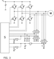
- Figure 1 shows a circuit of a known brushless motor M.
- the brushless motor M or BLDC motor M for short, is controlled or operated via a control unit S in the form of a regulated frequency converter S.
- a three-phase rotating field is applied to the BLDC motor M from a direct voltage V DC as the intermediate circuit voltage V DC via a B6 bridge with six transistors T1-T6 and six diodes D1-D6. This causes a rotation of a rotor (not shown) of the BLDC motor M during operation.
- the rotor position In order for the rotating field applied to the stator (not shown) of the BLDC motor M to match the rotor position, the rotor position must be determined. In the past, this was done using a sensor on the BLDC motor M. With the advent of sensorless control, the sensor was replaced by the measurement of electrical quantities in combination with a software motor model on the control unit S. For this purpose, the phase voltages U Phase of the three phases U, V, W and also the star point voltage were measured. The star point voltage can either be measured at the star point of the BLDC motor M or simulated and measured using an "artificial star point."
- the circuit of the ohmic resistors R8-R10 and the capacitor C5 represents the artificial star point. In a BLDC motor M with a delta connection, only the artificial star point is usually used.
- FIG 2 shows the waveforms of the phase voltages U Phase of the three phases U, V, W of the brushless motor M of the Figure 1
- phase U is actively subjected to a positive voltage for 120° (two sectors).
- phase U is de-energized and voltage-free.
- the induced voltage ⁇ U of phase U can be measured, which is also referred to as the electromotive force (EMF).
- EMF electromotive force
- Such BLDC motors M are usually monitored for excessive heating or overheating, i.e., thermal protection of the BLDC motor M is usually provided. If, for example, the BLDC motor M is blocked and is still energized, this can lead to very high currents in the stator coils and thus to overheating of the BLDC motor M.
- thermal protection of the BLDC motor M is usually provided. If, for example, the BLDC motor M is blocked and is still energized, this can lead to very high currents in the stator coils and thus to overheating of the BLDC motor M.
- the BLDC motor M rotates, a voltage is induced in the stator windings. This induced voltage ensures that the current in the stator winding is limited. If the BLDC motor M is stationary or even rotates very slowly, for example because the BLDC motor M is very stiff, and is still energized, this can lead to very high currents and thus to overheating of the stator winding.
- the information about whether the rotor of the BLDC motor M is rotating, stationary, or rotating very slowly is very useful for thermal protection. If the BLDC motor M does not start up despite the activation or energization of phases U, V, and W, the BLDC motor M should be shut down after a short time to prevent it from overheating. Therefore, it is advantageous to detect a standstill of the BLDC motor M.
- one or more procedures as described below can be carried out by means of safety-related software, in which the filtered star point voltage via the capacitor C6 and via the ohmic resistor R12 and a filtered phase voltage U Phase via the capacitor C7 and via the ohmic resistor R13 of the BLDC motor M are recorded by the control unit S.
- the values of the neutral point voltage and the phase voltage U Phase are filtered to filter the PWM control.
- the filters used for neutral point voltage and phase voltage measurements have a certain known characteristic. For example, the amplitude of the voltages is more strongly attenuated at higher frequencies than at lower frequencies. By recording the frequency, the measured voltage can be corrected for the filter attenuation. This further increases the accuracy of the inventive methods, which are described below.
- the difference in voltages is the phase voltage of the BLDC motor M. Neglecting the voltage drop across the resistor and the inductance, the measured voltage difference corresponds approximately to the induced voltage EMF of the BLDC motor M.
- the induced voltage EMF is proportional to the speed of the BLDC motor M, which is why this proportional relationship, see Figure 4 , which allows the speed of the BLDC motor M to be determined.
- Both the ohmic resistance and the inductance of the BLDC motor M should be relatively small so that the method can be applied as reliably and accurately as possible. This is typically the case with compact BLDC motors M used in cordless vacuum cleaners.
- a method can be carried out according to the invention by energizing 100 two phases U, V, W, detecting 200 the phase voltage U Phase , detecting 250 the star point voltage, determining 300 the differential voltage ⁇ U as the difference between the detected phase voltage U Phase and the detected star point voltage, determining 400a a first change of sign of the detected differential voltage ⁇ U at a first point in time, determining 450a a second change of sign in the same direction of the detected differential voltage ⁇ U at a second point in time, determining 500a the time difference between the first point in time of the first change of sign and the second point in time of the second change of sign and determining 550a the speed of the brushless motor M based on the determined time difference.
- a frequency measurement of the differential voltage ⁇ U can be performed by triggering a comparator through a sign change when comparing the filtered phase voltage U phase and the filtered neutral point voltage. Only the positive or negative edge triggers, and an interrupt is triggered. A coupled counter records the number of clock cycles until the next interrupt occurs, thus determining the frequency of the differential voltage ⁇ U.
- the detection of the rotational speed is included in the Figure 5 presented as an example (idealized).
- a method can be carried out according to the invention by energizing 100 the motor M, detecting 200 the phase voltage U Phase , detecting 250 the star point voltage, determining 300 the differential voltage ⁇ U as the difference between the detected phase voltage U Phase and the detected star point voltage, determining 400b at least one extreme value of the determined differential voltage ⁇ U and determining 450b the speed of the brushless motor M based on the determined extreme value.
- a voltage measurement can be performed by appropriately sampling the differential voltage and recording the curve of the differential voltage ⁇ U by the control unit S, and determining both the maximum and minimum values within a period.
- the differential voltage ⁇ U is proportional to the speed, and thus the speed can be determined using one or both values.
- This second method can be extended in that the determination 400b is carried out for at least two extreme values of the determined differential voltage ⁇ U and that a determination 500b of the difference between the two determined extreme values, a comparison 550b of the determined difference with a predetermined limit value and, if the predetermined limit value is exceeded or reached, a triggering 580b of a reaction, preferably a reduction 580b or a termination 580b of the current supply 100 of the two phases U, V, W, takes place.
- the determined maximum and minimum values of the determined differential voltage ⁇ U must be virtually identical in magnitude during a period. If the difference between the two values is greater than a certain limit, the voltage measurement is incorrect or an error has occurred. This allows the second method to be validated for its own plausibility, thus preventing the determination of an incorrect speed according to the second method. This can increase the safety and reliability of this second method itself.
- Both previously described methods according to the invention can also be carried out in parallel to one another and their determined speeds can be checked for plausibility against one another by determining 600d the difference between the two determined speeds, comparing 650d the determined difference with a predetermined limit value and, if the predetermined limit value is exceeded, triggering 700d a reaction, preferably reducing 700d or terminating 700d the current supply 100.
- the speed is determined from the frequency measurement of the determined differential voltage ⁇ U.
- the speed is also determined from the amplitude of the determined differential voltage ⁇ U, as previously described in the second method. Both determined speeds must be almost identical. If the deviation of the values is greater than a certain limit, there is an error in the measured value acquisition and/or evaluation. Safe and reliable temperature monitoring of the BLDC motor M based on its determined speed is then not possible.
- the advantages of the method according to the invention and the corresponding control devices can be seen in the fact that, by measuring two filtered electrical variables, the speed of the BLDC motor M can be recorded and independently verified. From an approval perspective, the verification of the speed is essential if safety-related software is used for thermal protection of the BLDC motor M. The speed measurement can be used to detect the standstill of the BLDC motor M. and shut down. Furthermore, speed-dependent current limits can be set in the software, which can also be beneficial for protecting the BLDC motor M.
Landscapes
- Engineering & Computer Science (AREA)
- Power Engineering (AREA)
- Control Of Motors That Do Not Use Commutators (AREA)
Claims (9)
- Procédé pour la surveillance thermique d'un moteur (M) sans balais à au moins deux phases sans capteur de position de rotor, comportant au moins les étapes consistant à :• alimenter en courant (100) le moteur (M), dans lequel la tension de phase (UPhase) de l'alimentation en courant (100) est de préférence réglée au moyen d'une commande MIL,• détecter (200) la tension de phase (UPhase),• détecter (250) la tension de point neutre,• déterminer (300) la tension différentielle (ΔU) entre la tension de phase (UPhase) détectée et la tension de point neutre détectée,• déterminer (400a) un premier changement de signe de la tension différentielle (ΔU) déterminée à un premier moment,• déterminer (450a) un second changement de signe de même sens de la tension différentielle (ΔU) déterminée à un second moment,• déterminer (500a) la différence de temps entre le premier moment du premier changement de signe et le second moment du second changement de signe,• déterminer (550a) la vitesse de rotation du moteur (M) sans balais sur la base de la différence de temps déterminée, caractérisé par• la détermination (400b) d'au moins une valeur extrême de la tension différentielle (ΔU) déterminée,• la détermination (450b) de la vitesse de rotation du moteur (M) sans balais sur la base de la valeur extrême déterminée,• la comparaison (600c) de la vitesse de rotation respectivement déterminée avec une vitesse de rotation prédéterminée,en cas de non-atteinte respective ou en cas d'atteinte respectivede la vitesse de rotation prédéterminée, la réduction (700c)ou l'arrêt (700c) de l'alimentation en courant (100) du moteur (M),la détermination (600d) de la différence entre les deux vitesses de rotation déterminées, la comparaison (650d) de ladifférence déterminée avec une valeur limite prédéfinie, et en cas de dépassement de la valeur limite prédéfinie,le déclenchement (700d) d'une réduction(700d) ou d'un arrêt (700d) de l'alimentation en courant (100) du moteur (M).
- Procédé selon la revendication 1, caractérisé en ce quela détermination (400b) est effectuée pour au moins deux valeurs extrêmes de la tension différentielle (ΔU) déterminée, etcomportant les étapes supplémentaires consistant à :• déterminer (500b) la différence entre les deux valeurs extrêmes déterminées,• comparer (550b) la différence déterminée avec une valeur limite prédéfinie, et• en cas de dépassement ou d'atteinte de la valeur limite prédéfinie, déclencher (580b) une réaction, de préférence réduire (580b) ou arrêter (580b) l'alimentation en courant (100) du moteur (M).
- Procédé selon l'une des revendications précédentes,
caractérisé en ce que la détection (200) de la tension de phase (UPhase) est effectuée de manière filtrée. - Procédé selon l'une des revendications précédentes,
caractérisé en ce que la détection (250) de la tension de point neutre est effectuée de manière filtrée. - Dispositif de commande pour la surveillance thermique d'un moteur (M) sans balais à au moins deux phases sans capteur de position de rotor,comportant une unité de commande (S) qui est configurée pour alimenter en courant le moteur (M), dans lequel la tension de phase (UPhase) de l'alimentation en courant (100) est de préférence réglée au moyen d'une commande MIL, etcomportant un appareil de balayage qui est configuré pour détecter la tension de phase (UPhase) et la tension de point neutre,dans lequel l'unité de commande (S) est en outre configurée pourdéterminer la tension différentielle (ΔU) comme différence entre la tension de phase (UPhase) détectée et la tension de point neutre détectée,déterminer un premier changement de signe de la tension (ΔU) déterminée à un premier moment,déterminer un second changement de signe de même sens de la tension (ΔU) déterminée à un second moment,déterminer la différence de temps entre le premier moment du premier changement de signe et le second moment du second changement de signe, etdéterminer la vitesse de rotation du moteur (M) sans balais sur la base de la différence de temps déterminée,déterminer au moins une valeur extrême de la tension différentielle (ΔU) déterminée,déterminer la vitesse de rotation du moteur (M) sans balais sur la base de la différence de temps déterminée, caractérisé en ce que l'unité de commande (S) est en outre configurée pour déterminer au moins une valeur extrême de la tension différentielle (ΔU) déterminée, pour déterminer la vitesse de rotation du moteur (M) sans balais sur la base de la valeur extrême déterminée, pour comparer (600c) la vitesse de rotation respectivement déterminée avec une vitesse de rotation prédéfinie, en cas de non-atteinte respective ou en cas d'atteinte respectivede la vitesse de rotation prédéfinie, pour réduire (700c) ou pour arrêter (700c) l'alimentation en courant (100) du moteur (M),pour déterminer (600d) la différence entre les deux vitesses de rotation déterminées,pour comparer (650d) la différence déterminée avec une valeur limite prédéfinie, eten cas de dépassement de la valeur limite prédéfinie, pour déclencher une réduction (700d) ou un arrêt (700d) de l'alimentation en courant (100) du moteur (M).
- Dispositif de commande selon la revendication 5, dans lequel l'unité de commande (S) est en outre configurée pourréaliser la détermination (400b) pour au moins deux valeurs extrêmes de la tension différentielle (ΔU) déterminée,déterminer (500b) la différence entre les deux valeurs extrêmes déterminées,comparer (550b) la différence déterminée avec une valeur limite prédéfinie, eten cas de dépassement ou d'atteinte de la valeur limite prédéfinie, déclencher une réduction (700d) ou un arrêt (700d) de l'alimentation en courant (100) du moteur (M).
- Moteur (M) sans balais à au moins trois phases sans capteur de position de rotor, comportant un dispositif de commande selon la revendication 5 ou 6.
- Appareil électroménager comportant au moins un moteur (M) sans balais à au moins deux phases selon la revendication 7.
- Appareil électroménager selon la revendication 8, caractérisé en ce que
l'appareil électroménager présente un accumulateur d'énergie électrique, de préférence rechargeable, et est configuré pour fonctionner au moyen de l'énergie électrique accumulée de l'accumulateur d'énergie électrique.
Applications Claiming Priority (1)
| Application Number | Priority Date | Filing Date | Title |
|---|---|---|---|
| BE20215032A BE1029031B1 (de) | 2021-01-20 | 2021-01-20 | Verfahren zur thermischen Überwachung eines mindestens zweiphasigen bürstenlosen Motors |
Publications (3)
| Publication Number | Publication Date |
|---|---|
| EP4033655A1 EP4033655A1 (fr) | 2022-07-27 |
| EP4033655C0 EP4033655C0 (fr) | 2025-03-12 |
| EP4033655B1 true EP4033655B1 (fr) | 2025-03-12 |
Family
ID=74504953
Family Applications (1)
| Application Number | Title | Priority Date | Filing Date |
|---|---|---|---|
| EP22151076.1A Active EP4033655B1 (fr) | 2021-01-20 | 2022-01-12 | Procédé et dispositif d'entraînement de surveillance thermique d'un moteur sans balai au moins biphasé |
Country Status (2)
| Country | Link |
|---|---|
| EP (1) | EP4033655B1 (fr) |
| BE (1) | BE1029031B1 (fr) |
Family Cites Families (7)
| Publication number | Priority date | Publication date | Assignee | Title |
|---|---|---|---|---|
| US5327053A (en) * | 1992-08-12 | 1994-07-05 | Seagate Technology, Inc. | Apparatus and method for detecting rotor position in a sensorless and brushless DC motor |
| US5473240A (en) * | 1993-12-30 | 1995-12-05 | Whirlpool Corporation | Motor control using third harmonic stator voltage signal |
| JP5891410B2 (ja) * | 2012-03-13 | 2016-03-23 | パナソニックIpマネジメント株式会社 | 電動工具 |
| DE102017121829A1 (de) * | 2017-09-20 | 2019-03-21 | Minebea Mitsumi Inc. | Verfahren zum Betreiben eines sensorlos, elektronisch kommutierten, mehrphasigen Elektromotors |
| JP2019193445A (ja) * | 2018-04-25 | 2019-10-31 | 日本電産株式会社 | モータ駆動装置 |
| KR102362995B1 (ko) * | 2018-06-28 | 2022-02-16 | 한국전자기술연구원 | 모터 구동 장치 및 시스템 |
| JP7695060B2 (ja) * | 2019-05-22 | 2025-06-18 | ロベルト・ボッシュ・ゲゼルシャフト・ミト・ベシュレンクテル・ハフツング | ステッピングモータのストールまたはステップロスを検出する制御ユニットおよび方法 |
-
2021
- 2021-01-20 BE BE20215032A patent/BE1029031B1/de not_active IP Right Cessation
-
2022
- 2022-01-12 EP EP22151076.1A patent/EP4033655B1/fr active Active
Also Published As
| Publication number | Publication date |
|---|---|
| BE1029031B1 (de) | 2022-08-23 |
| EP4033655A1 (fr) | 2022-07-27 |
| BE1029031A1 (de) | 2022-08-16 |
| EP4033655C0 (fr) | 2025-03-12 |
Similar Documents
| Publication | Publication Date | Title |
|---|---|---|
| DE69723913T2 (de) | System und Verfahren zum Schutz eines Einphasenmotors vor Freilaufströmen | |
| DE69805641T2 (de) | Gerät und verfahren zur steuerung eines synchronmotors mit permanentmagnet | |
| EP1076408B1 (fr) | Procédé de démarrage d'un moteur à courant continu sans balais | |
| DE102012102868A1 (de) | Verfahren zum Betreiben eines bürstenlosen Elektromotors | |
| WO2013156571A2 (fr) | Commande destinée à un moteur à courant continu sans balai | |
| EP1215810B1 (fr) | Procédé de commande sans capteur | |
| EP4372977A1 (fr) | Système d'entraînement | |
| EP4033655B1 (fr) | Procédé et dispositif d'entraînement de surveillance thermique d'un moteur sans balai au moins biphasé | |
| DE19820929A1 (de) | Vorrichtung zum Steuern eines Einphasen-Synchronmotors | |
| DE102016123741A1 (de) | Verfahren zum Erkennen einer mechanischen Blockierung im Betrieb eines Elektromotors | |
| EP3602772B1 (fr) | Procédé pour faire fonctionner un moteur électrique et démarreur progressif | |
| EP4030617B1 (fr) | Procédé de surveillance thermique d'un moteur sans balai | |
| DE69732701T2 (de) | Verfahren und vorrichtung zur steuerung von elektrischen motor-generatoren | |
| EP4037183B1 (fr) | Surveillance thermique de deux moteurs | |
| BE1029061B1 (de) | Verfahren zum Ansteuern eines mindestens zweiphasigen bürstenlosen Motors | |
| EP4358391A1 (fr) | Système d'entraînement | |
| EP4037178B1 (fr) | Procédé de commande d'un moteur sans balai au moins biphasé | |
| EP4142146B1 (fr) | Système d'entraînement | |
| BE1029062B1 (de) | Verfahren zum Ansteuern eines mindestens zweiphasigen bürstenlosen Motors | |
| EP1796258B1 (fr) | Moteur électrique et procédé de son excitation | |
| EP1048774A2 (fr) | Procédé et dispositif pour détecter le balourd d'un rotor entrainé par un moteur électrique sans balais | |
| EP4550656A1 (fr) | Procédé de fonctionnement biphasé d'un moteur synchrone triphasé à excitation permanente | |
| EP4033656A1 (fr) | Procédé de commande d'un moteur sans balai au moins biphasé | |
| EP4593281A1 (fr) | Système d'entraînement | |
| EP4704325A1 (fr) | Commande d'un moteur à courant continu sans balai au moins triphasé |
Legal Events
| Date | Code | Title | Description |
|---|---|---|---|
| PUAI | Public reference made under article 153(3) epc to a published international application that has entered the european phase |
Free format text: ORIGINAL CODE: 0009012 |
|
| STAA | Information on the status of an ep patent application or granted ep patent |
Free format text: STATUS: THE APPLICATION HAS BEEN PUBLISHED |
|
| AK | Designated contracting states |
Kind code of ref document: A1 Designated state(s): AL AT BE BG CH CY CZ DE DK EE ES FI FR GB GR HR HU IE IS IT LI LT LU LV MC MK MT NL NO PL PT RO RS SE SI SK SM TR |
|
| STAA | Information on the status of an ep patent application or granted ep patent |
Free format text: STATUS: REQUEST FOR EXAMINATION WAS MADE |
|
| 17P | Request for examination filed |
Effective date: 20230127 |
|
| RBV | Designated contracting states (corrected) |
Designated state(s): AL AT BE BG CH CY CZ DE DK EE ES FI FR GB GR HR HU IE IS IT LI LT LU LV MC MK MT NL NO PL PT RO RS SE SI SK SM TR |
|
| GRAP | Despatch of communication of intention to grant a patent |
Free format text: ORIGINAL CODE: EPIDOSNIGR1 |
|
| STAA | Information on the status of an ep patent application or granted ep patent |
Free format text: STATUS: GRANT OF PATENT IS INTENDED |
|
| INTG | Intention to grant announced |
Effective date: 20241212 |
|
| GRAS | Grant fee paid |
Free format text: ORIGINAL CODE: EPIDOSNIGR3 |
|
| GRAA | (expected) grant |
Free format text: ORIGINAL CODE: 0009210 |
|
| STAA | Information on the status of an ep patent application or granted ep patent |
Free format text: STATUS: THE PATENT HAS BEEN GRANTED |
|
| AK | Designated contracting states |
Kind code of ref document: B1 Designated state(s): AL AT BE BG CH CY CZ DE DK EE ES FI FR GB GR HR HU IE IS IT LI LT LU LV MC MK MT NL NO PL PT RO RS SE SI SK SM TR |
|
| REG | Reference to a national code |
Ref country code: GB Ref legal event code: FG4D Free format text: NOT ENGLISH |
|
| REG | Reference to a national code |
Ref country code: CH Ref legal event code: EP |
|
| REG | Reference to a national code |
Ref country code: DE Ref legal event code: R096 Ref document number: 502022003132 Country of ref document: DE |
|
| REG | Reference to a national code |
Ref country code: IE Ref legal event code: FG4D Free format text: LANGUAGE OF EP DOCUMENT: GERMAN |
|
| U01 | Request for unitary effect filed |
Effective date: 20250312 |
|
| U07 | Unitary effect registered |
Designated state(s): AT BE BG DE DK EE FI FR IT LT LU LV MT NL PT RO SE SI Effective date: 20250318 |
|
| REG | Reference to a national code |
Ref country code: GB Ref legal event code: 746 Effective date: 20250402 |
|
| PG25 | Lapsed in a contracting state [announced via postgrant information from national office to epo] |
Ref country code: RS Free format text: LAPSE BECAUSE OF FAILURE TO SUBMIT A TRANSLATION OF THE DESCRIPTION OR TO PAY THE FEE WITHIN THE PRESCRIBED TIME-LIMIT Effective date: 20250612 |
|
| PG25 | Lapsed in a contracting state [announced via postgrant information from national office to epo] |
Ref country code: ES Free format text: LAPSE BECAUSE OF FAILURE TO SUBMIT A TRANSLATION OF THE DESCRIPTION OR TO PAY THE FEE WITHIN THE PRESCRIBED TIME-LIMIT Effective date: 20250312 |
|
| PG25 | Lapsed in a contracting state [announced via postgrant information from national office to epo] |
Ref country code: NO Free format text: LAPSE BECAUSE OF FAILURE TO SUBMIT A TRANSLATION OF THE DESCRIPTION OR TO PAY THE FEE WITHIN THE PRESCRIBED TIME-LIMIT Effective date: 20250612 |
|
| PG25 | Lapsed in a contracting state [announced via postgrant information from national office to epo] |
Ref country code: HR Free format text: LAPSE BECAUSE OF FAILURE TO SUBMIT A TRANSLATION OF THE DESCRIPTION OR TO PAY THE FEE WITHIN THE PRESCRIBED TIME-LIMIT Effective date: 20250312 |
|
| PG25 | Lapsed in a contracting state [announced via postgrant information from national office to epo] |
Ref country code: GR Free format text: LAPSE BECAUSE OF FAILURE TO SUBMIT A TRANSLATION OF THE DESCRIPTION OR TO PAY THE FEE WITHIN THE PRESCRIBED TIME-LIMIT Effective date: 20250613 |
|
| PG25 | Lapsed in a contracting state [announced via postgrant information from national office to epo] |
Ref country code: SM Free format text: LAPSE BECAUSE OF FAILURE TO SUBMIT A TRANSLATION OF THE DESCRIPTION OR TO PAY THE FEE WITHIN THE PRESCRIBED TIME-LIMIT Effective date: 20250312 |
|
| PG25 | Lapsed in a contracting state [announced via postgrant information from national office to epo] |
Ref country code: PL Free format text: LAPSE BECAUSE OF FAILURE TO SUBMIT A TRANSLATION OF THE DESCRIPTION OR TO PAY THE FEE WITHIN THE PRESCRIBED TIME-LIMIT Effective date: 20250312 |
|
| PG25 | Lapsed in a contracting state [announced via postgrant information from national office to epo] |
Ref country code: CZ Free format text: LAPSE BECAUSE OF FAILURE TO SUBMIT A TRANSLATION OF THE DESCRIPTION OR TO PAY THE FEE WITHIN THE PRESCRIBED TIME-LIMIT Effective date: 20250312 |
|
| PG25 | Lapsed in a contracting state [announced via postgrant information from national office to epo] |
Ref country code: SK Free format text: LAPSE BECAUSE OF FAILURE TO SUBMIT A TRANSLATION OF THE DESCRIPTION OR TO PAY THE FEE WITHIN THE PRESCRIBED TIME-LIMIT Effective date: 20250312 |
|
| PG25 | Lapsed in a contracting state [announced via postgrant information from national office to epo] |
Ref country code: IS Free format text: LAPSE BECAUSE OF FAILURE TO SUBMIT A TRANSLATION OF THE DESCRIPTION OR TO PAY THE FEE WITHIN THE PRESCRIBED TIME-LIMIT Effective date: 20250712 |
|
| PLBE | No opposition filed within time limit |
Free format text: ORIGINAL CODE: 0009261 |
|
| STAA | Information on the status of an ep patent application or granted ep patent |
Free format text: STATUS: NO OPPOSITION FILED WITHIN TIME LIMIT |
|
| REG | Reference to a national code |
Ref country code: CH Ref legal event code: L10 Free format text: ST27 STATUS EVENT CODE: U-0-0-L10-L00 (AS PROVIDED BY THE NATIONAL OFFICE) Effective date: 20260121 |
|
| 26N | No opposition filed |
Effective date: 20251215 |
|
| U20 | Renewal fee for the european patent with unitary effect paid |
Year of fee payment: 5 Effective date: 20260202 |
|
| PGFP | Annual fee paid to national office [announced via postgrant information from national office to epo] |
Ref country code: GB Payment date: 20260126 Year of fee payment: 5 |
|
| PGFP | Annual fee paid to national office [announced via postgrant information from national office to epo] |
Ref country code: TR Payment date: 20260106 Year of fee payment: 5 |