EP4147626A1 - Lave-vaisselle avec unité d'extraction de vapeur - Google Patents
Lave-vaisselle avec unité d'extraction de vapeur Download PDFInfo
- Publication number
- EP4147626A1 EP4147626A1 EP22191116.7A EP22191116A EP4147626A1 EP 4147626 A1 EP4147626 A1 EP 4147626A1 EP 22191116 A EP22191116 A EP 22191116A EP 4147626 A1 EP4147626 A1 EP 4147626A1
- Authority
- EP
- European Patent Office
- Prior art keywords
- compartment
- chamber
- air
- machine
- condenser
- Prior art date
- Legal status (The legal status is an assumption and is not a legal conclusion. Google has not performed a legal analysis and makes no representation as to the accuracy of the status listed.)
- Granted
Links
Images


Classifications
-
- A—HUMAN NECESSITIES
- A47—FURNITURE; DOMESTIC ARTICLES OR APPLIANCES; COFFEE MILLS; SPICE MILLS; SUCTION CLEANERS IN GENERAL
- A47L—DOMESTIC WASHING OR CLEANING; SUCTION CLEANERS IN GENERAL
- A47L15/00—Washing or rinsing machines for crockery or tableware
- A47L15/0018—Controlling processes, i.e. processes to control the operation of the machine characterised by the purpose or target of the control
- A47L15/0021—Regulation of operational steps within the washing processes, e.g. optimisation or improvement of operational steps depending from the detergent nature or from the condition of the crockery
- A47L15/0028—Washing phases
-
- A—HUMAN NECESSITIES
- A47—FURNITURE; DOMESTIC ARTICLES OR APPLIANCES; COFFEE MILLS; SPICE MILLS; SUCTION CLEANERS IN GENERAL
- A47L—DOMESTIC WASHING OR CLEANING; SUCTION CLEANERS IN GENERAL
- A47L15/00—Washing or rinsing machines for crockery or tableware
- A47L15/0018—Controlling processes, i.e. processes to control the operation of the machine characterised by the purpose or target of the control
- A47L15/0021—Regulation of operational steps within the washing processes, e.g. optimisation or improvement of operational steps depending from the detergent nature or from the condition of the crockery
- A47L15/0034—Drying phases, including dripping-off phases
-
- A—HUMAN NECESSITIES
- A47—FURNITURE; DOMESTIC ARTICLES OR APPLIANCES; COFFEE MILLS; SPICE MILLS; SUCTION CLEANERS IN GENERAL
- A47L—DOMESTIC WASHING OR CLEANING; SUCTION CLEANERS IN GENERAL
- A47L15/00—Washing or rinsing machines for crockery or tableware
- A47L15/0076—Washing or rinsing machines for crockery or tableware of non-domestic use type, e.g. commercial dishwashers for bars, hotels, restaurants, canteens or hospitals
- A47L15/0081—Washing or rinsing machines for crockery or tableware of non-domestic use type, e.g. commercial dishwashers for bars, hotels, restaurants, canteens or hospitals with vertical sliding closing doors, e.g. hood-type dishwashers
-
- A—HUMAN NECESSITIES
- A47—FURNITURE; DOMESTIC ARTICLES OR APPLIANCES; COFFEE MILLS; SPICE MILLS; SUCTION CLEANERS IN GENERAL
- A47L—DOMESTIC WASHING OR CLEANING; SUCTION CLEANERS IN GENERAL
- A47L15/00—Washing or rinsing machines for crockery or tableware
- A47L15/42—Details
- A47L15/48—Drying arrangements
- A47L15/483—Drying arrangements by using condensers
-
- A—HUMAN NECESSITIES
- A47—FURNITURE; DOMESTIC ARTICLES OR APPLIANCES; COFFEE MILLS; SPICE MILLS; SUCTION CLEANERS IN GENERAL
- A47L—DOMESTIC WASHING OR CLEANING; SUCTION CLEANERS IN GENERAL
- A47L15/00—Washing or rinsing machines for crockery or tableware
- A47L15/42—Details
- A47L15/48—Drying arrangements
- A47L15/486—Blower arrangements
-
- A—HUMAN NECESSITIES
- A47—FURNITURE; DOMESTIC ARTICLES OR APPLIANCES; COFFEE MILLS; SPICE MILLS; SUCTION CLEANERS IN GENERAL
- A47L—DOMESTIC WASHING OR CLEANING; SUCTION CLEANERS IN GENERAL
- A47L15/00—Washing or rinsing machines for crockery or tableware
- A47L15/42—Details
- A47L15/48—Drying arrangements
- A47L15/488—Connections of the tub with the ambient air, e.g. air intake or venting arrangements
-
- A—HUMAN NECESSITIES
- A47—FURNITURE; DOMESTIC ARTICLES OR APPLIANCES; COFFEE MILLS; SPICE MILLS; SUCTION CLEANERS IN GENERAL
- A47L—DOMESTIC WASHING OR CLEANING; SUCTION CLEANERS IN GENERAL
- A47L2401/00—Automatic detection in controlling methods of washing or rinsing machines for crockery or tableware, e.g. information provided by sensors entered into controlling devices
- A47L2401/18—Air temperature
-
- A—HUMAN NECESSITIES
- A47—FURNITURE; DOMESTIC ARTICLES OR APPLIANCES; COFFEE MILLS; SPICE MILLS; SUCTION CLEANERS IN GENERAL
- A47L—DOMESTIC WASHING OR CLEANING; SUCTION CLEANERS IN GENERAL
- A47L2501/00—Output in controlling method of washing or rinsing machines for crockery or tableware, i.e. quantities or components controlled, or actions performed by the controlling device executing the controlling method
- A47L2501/11—Air heaters
Definitions
- This application relates generally to warewash machines and, more specifically, to a hood-type warewash machine with a controlled extraction of hot water vapor.
- Warewash machines have become fairly standardized in the industry.
- a standard warewasher has a washing chamber with an access opening that allows wares to be placed within the chamber for a washing operation.
- a typical hood-type warewash machine includes a housing that, in part, defines a wash zone having front, left and right access openings, and at least one spray arm disposed above and/or below the wash zone.
- a multi-sided hood assembly is movable between a down/closed position for washing and an up/open position for inlet and outlet of wares. In the closed position, the multi-sided hood assembly closes the front, left and right access openings, and in the open position, the front, left and right access openings are open to permit access to the wash zone for inlet and egress of wares.
- the chamber fills with hot water vapor.
- the cycle is complete, and the operator raises the hood/door, a large amount of hot water vapor exits the machine, making for an uncomfortable work environment.
- the hot water vapor that leaves the machine also rises to the ceiling and can contact the facility walls, causing the ceiling to drip water and generally creating a hot work environment that may need to be conditioned, increasing facility costs.
- a warewash machine in one aspect, includes a housing that at least in part defines a chamber with a wash zone, the chamber having front, left and right access openings. At least one spray arm is disposed above or below the wash zone, the spray arm configured to spray liquid toward the wash zone.
- a multi-sided hood assembly includes multiple wall sections, the multi-sided hood assembly movable between a lowered and closed position for washing and a raised and open position for inlet and outlet of wares, wherein in the raised and open position each of the multiple wall sections is raised.
- An air exchange system is fluidly connected with the chamber and includes an extraction compartment and an intake compartment, both the extraction compartment and the intake compartment located externally of the chamber.
- the extraction compartment includes a condenser therein, wherein an incoming water path to the machine from a cold water input passes through the condenser.
- the extraction compartment includes an air outlet to a surrounding ambient environment, a first air mover associated with the extraction compartment and selectively controllable for moving hot water vapor from the chamber, into the extraction compartment, over the condenser and out of the air outlet.
- the intake compartment includes at a least one heater therein and an air inlet from the surrounding ambient environment, and a second air mover associated with the intake compartment and selectively controllable for moving ambient air into the intake compartment via the air inlet, past the heater to be heated and into the chamber.
- a warewash machine 10 includes a housing 12 (e.g., with support frame and panels) in part defining a chamber 14 with a wash zone 16.
- the chamber 14 includes front 18, left 20 and right 22 access openings through which wares can be moved in and out of the chamber for cleaning.
- One or more spray arms e.g., wash arm(s) 23a and rinse arm(s) 23b having respective wash nozzles and rinse nozzles
- the spray arms are configured to spray liquid toward the wash zone 16.
- both a wash spray arm 23a and a rinse spray arm 23b may be provided, with the wash spray arm fed by a pump 24 ( Fig.
- the arms may, for example, be rotating arms and/or fixed arms. Upper and lower sets of arms may be implemented.
- a multi-sided hood assembly 30 includes movable front 32, left 36, right 38 and top 40 wall sections (e.g., forming a box-like hood structure that is open at the bottom) and the hood assembly may or may not have a moving back wall section 34.
- the wall sections move together as a unit, such that the multi-sided hood assembly is movable (per arrow 42) between a lowered closed position (e.g., per Fig. 3 ) for washing and a raised open position (e.g., per Fig. 1 ) for inlet and outlet of wares.
- the hood assembly When the multi-sided hood assembly is in the closed position, the hood assembly closes the front 18, left 20 and right 22 access openings so that cleaning sprays within the chamber will be contained during ware cleaning. When the multi-sided hood assembly is in the open position, the front 18, left 20 and right 22 access openings are open as shown in Fig. 1 to permit access to the wash zone for inlet and egress of wares.
- a pivot handle 44 may be provided to facilitate operator movement of the hood assembly 30.
- a stationary chamber rear wall 50 is disposed at the back side of the wash chamber and, in embodiments in which the hood assembly includes a rear wall section 34, the wall 50 is at least partly behind the wall section 34 when the hood is closed.
- the rear wall 50 includes an outlet opening 52, and in embodiments including the rear wall section 34, the rear wall section 34 may include a cutout so as to avoid blocking the opening 52 when the hood is closed.
- the outlet opening 52 is fluidly connected with a vapor extraction unit 54 ( Fig. 2 ) at a back side of the rear wall 50.
- the vapor extraction unit 54 includes an enclosure 56 with a condenser 58, including a condenser coil, therein.
- incoming cold water to the machine from a cold water line input 90 passes through the condenser 58.
- An enclosure outlet 60 ( Fig. 2 ) to surrounding ambient environment is also provided, here at the top of the enclosure.
- At least one air mover 62 e.g., here two side-by-side axial fans 62a
- the axial fans 62 are mounted over the enclosure outlet 60.
- Other types of air movers e.g., other fan types or blowers
- a machine controller 100 ( Fig. 1 ) is provided for controlling ware cleaning cycles of the machine, where the cycles include both a wash operation and then a rinse operation.
- the term controller is intended to broadly encompass any circuit (e.g., solid state, application specific integrated circuit (ASIC), an electronic circuit, a combinational logic circuit, a field programmable gate array (FPGA)), processor(s) (e.g., shared, dedicated, or group - including hardware or software that executes code), software, firmware and/or other components, or a combination of some or all of the above, that carries out the control functions of the machine or the control functions of any component thereof.
- ASIC application specific integrated circuit
- FPGA field programmable gate array
- the controller 100 is configured to operate the water vapor extraction unit 54 by controlling each of (i) water flow through the condenser 58 (e.g., by opening solenoid valve 90a, or alternatively operating a pump or other flow control device) and (ii) operation of the air mover(s) (e.g., by connecting power to the fan motor) such that, at least after the rinse operation of the ware cleaning operation is completed, hot water vapor is pulled from the chamber through the vapor extraction unit while cold water flows through the condenser 58. This process results in condensation of water vapor from the moist air, such that the air that passes to the enclosure outlet 60 is not excessively hot and/or moist.
- the hot water vapor extraction unit 54 includes an internal water flow path for condensed water to flow from the unit back into the chamber.
- the illustrated water flow path passes through the outlet opening to reach the chamber (e.g., the bottom wall 64a of the enclosure housing 64 is angled to direct falling condensate back through the opening 52).
- the enclosure is formed in part by a secondary housing 64 and in part by the rear wall 50 of the machine housing, wherein the secondary housing 64 is mounted to the back side of the rear wall, with a gasket 66 along at least a majority of the perimeter of the housing to wall interface for sealing.
- the outlet opening 52 is located on a lower portion 68 of the rear wall (e.g., the lower 1/3 of the portion of the rear wall aligned with the chamber 12, or the lower 1/4 or the lower 1/5).
- hot water vapor (indicated by arrows 70 in Fig. 3 ) is drawn from a lower portion of the chamber, while make-up air 72 enters the chamber by passing under the bottom of the front, left and/or right wall sections of the multi-sided hood assembly (e.g., see Fig. 4 ).
- the volume of air drawn through the vapor extraction unit after the rinse operation of a cycle may be set to help assure that moist hot vapors are retained in the upper portion 74 of the hood assembly (e.g., by drawing a volume of air that is less than the volume within the hood assembly, such as drawing a volume that is less than 50% of the overall hood volume, or less than 40% of the overall hood volume or less than 30% of the overall hood volume).
- the hood assembly 30 could be raised slightly (either manually or automatically by the controller) at the end of the rinse operation (as suggested by the hood assembly position in Fig. 4 ) in order to enhance in-flow of make-up air.
- the controller 100 is configured such that, upon completion of the rinse operation of a ware cleaning operation, the vapor extraction unit is operated for a set period of time (e.g., between 5 seconds and 30 seconds).
- the controller 100 is also configured to (i) initiate an end of cycle alert (e.g., a visible alert such as a light or indication on a machine interface 102 and/or an audible alert) only after operation of the vapor extraction unit is completed and/or (ii) lock the hood assembly down in the closed state until operation of the vapor extraction unit is completed.
- an end of cycle alert e.g., a visible alert such as a light or indication on a machine interface 102 and/or an audible alert
- a powered latch mechanism 80 (e.g., solenoid or motor operated) is movable between a hood latch state for holding the multi-sided hood assembly in the closed position and a hood unlatch state (shown in Fig. 3 ) that permits the multi-sided hood assembly to be moved to the open position.
- the ware cleaning cycle ends after the set time period and the controller 100 switches the powered latch mechanism to the hood unlatch state.
- the controller 100 is configured to maintain the powered latch mechanism 80 in the hood latch state during operation of the vapor extraction unit.
- the latch mechanism 80 includes a pivoting latch component 82 that engages some part of the hood assembly (e.g., the top rear edge of the hood assembly or a bracket as the rear of the the hood assembly) when rotated in the direction of arrow 84 for the purpose of the latching.
- a pivoting latch component 82 that engages some part of the hood assembly (e.g., the top rear edge of the hood assembly or a bracket as the rear of the the hood assembly) when rotated in the direction of arrow 84 for the purpose of the latching.
- the condenser 58 is fluidly connected to receive incoming water from the cold water input 90 of the machine (e.g., under control of valve 90a) and to then deliver the incoming water (via path 90b) to a heat exchanger 94 (e.g., with counterflow coil) that exchanges heat between the incoming water and water flowing to drain along a drain water flow path 96 from the chamber. After passing through the heat exchanger 94, the incoming water is delivered into a hot water booster 98 of the machine, which feeds the rinse arm(s) 23b.
- a hot water input 93 is connected to deliver incoming water (e.g., under control of solenoid valve 93a) to the sump/tank 26 of the chamber.
- the described system extracts water vapor at the end of each cycle, which condenses the water, before the chamber door hood is opened. This is achieved by drawing air from the lower portion of the chamber and having it pass over the condenser (e.g., including copper coil).
- the condenser has the cold incoming water running through it. The energy from the hot water vapor is transferred to the cold water running through the copper coil causing the water vapor to lose temperature and condensate.
- the condenser may use a cross flow heat exchange method. In one example, the water is primarily running horizontally through the coil, moving up within the enclosure only after a number of horizontal passes. The hot water vapor travels vertically up through the enclosure until it finally condensates. The cold water enters the bottom of the condenser and steadily increases temperatures until it finally exits at the top.
- the system reduces hot moist vapor exit upon door opening, improving the operator comfort and experience, as well as reducing room conditioning requirements.
- the water temperature of incoming water is also increased.
- the system may function with a fully enclosed hood.
- the goal is to maintain some hot water vapor inside the hood and only eliminate enough vapor so that it is not a problem for the operator.
- energy is maintained inside the machine and can be used for the next cycle. Removing primarily the vapor from the lower portion of the hood achieves this result.
- the positioning of the opening 52 to the unit 54, along with the CFM of the 2 axial fans, works together to allow the inside of the chamber to maintain the high-water vapor temperature while still eliminating the vapor that might typically escape when the door is opened at the end of a cycle.
- a controllable damper could be provided at or along the outlet 52, enabling a closed flow path during wash and rinse operations of a cleaning cycle, and then opening the flow path for the vapor extraction operation of the cycle.
- both an air extraction unit 105 and an air intake unit 107 are provided at the back side of the warewash machine 110, rearward of the chamber 116 and the rear wall 150.
- machine 110 is comparable to machine 110 in terms of overall configuration (e.g., with movable hood and wash and rinse systems and user interface as described above).
- the air extraction unit 105 and air intake unit 107 are formed with a combined housing or enclosure 156, with associated gasket 166, which housing 156 at least in part defines an extraction compartment 180 and an intake compartment 182.
- the compartments may be separated from each other by an internal enclosure wall 184 (e.g., creating two distinct flow paths that are substantially sealed from each other).
- the compartments 180 and 182 are also formed in part by the back side of the warewash machine, as above.
- Compartment 180 includes a condenser 158 therein, wherein incoming water to the machine from a cold water input passes through the condenser 158 (in a manner similar to that described above for machine 10).
- the air outlet 160 of compartment 180 leads to a surrounding ambient environment and one or more axial fans or other air mover 162 associated with the extraction compartment 180 and selectively controllable (e.g., by controller 200) for moving hot water vapor from the chamber 116, into the compartment 105, over the condenser 158 and then out of the air outlet 160 (e.g., per flow 190 in Fig. 7 ).
- the intake compartment 107 includes at a least one heater 155 therein and an air inlet 161 from the surrounding ambient environment, with one or more axial fans or other air mover 163 associated with the intake compartment 107 and selectively controllable (e.g., by controller 200) for moving ambient air into the air inlet, past the heater(s) 155 to be heated and then into the chamber 116 (e.g., per flow 192 in Fig. 8 ).
- the machine controller 200 may be configured with various user selectable cleaning cycles, one or more of which involve operation of both the extraction unit 105 and the intake unit 107.
- the controller 200 is configured to carry out a ware cleaning cycle that includes a wash operation and a rinse operation, with the controller further configured to operate the air exchange system 109 so as to (a) carry out an extraction operation that involves controlling each of (i) water flow through the condenser 158 and (ii) operation of the air mover 162 such that, at least after the rinse operation of the ware cleaning cycle is completed, hot water vapor is pulled from the chamber through the compartment 105 (over/past the condenser 158) and expelled from the air outlet 160 while water flows through the condenser 158; and (b) carry out a drying operation that involves controlling each of (i) energization of the heater 155 and (ii) operation of the air mover 163 such that, at least after the extraction operation of the ware cleaning cycle is completed, ambient air is pulled from through the air inlet
- the controller 200 is configured such that the drying operation occurs only after the air mover 162 is turned off to complete the extraction operation (i.e., no time overlap in air flows as between the extraction operation and the drying operation).
- a temperature sensor 196 is associated with the chamber 116
- the controller 200 may also be configured such that, during the drying operation, energization of the heater 155 is controlled such that a temperature within the chamber 116 as sensed by the temperature sensor 196 does not exceed a maximum threshold.
- the heater 155 could be deenergized when a set temperature (Tset) is reached and reenergized at a lower detected temperature (Tset - 5°F).
- Tset set temperature
- Tset lower detected temperature
- a more refined approach may be taken (e.g., varying the energization level of the heaters and/or turning off less than all heaters when more than one heater is present).
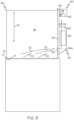
- FIG. 9 shows an air intake unit 107' that includes its own enclosure or housing 156-7 with associated gasket 166.
- the intake unit 107' is simply an additional component that is added to the machine 10 described above.
- Other changes and modifications are possible.
Landscapes
- Cleaning By Liquid Or Steam (AREA)
Applications Claiming Priority (1)
| Application Number | Priority Date | Filing Date | Title |
|---|---|---|---|
| US17/464,866 US11963649B2 (en) | 2017-12-21 | 2021-09-02 | Warewash machine with vapor extraction unit |
Publications (2)
| Publication Number | Publication Date |
|---|---|
| EP4147626A1 true EP4147626A1 (fr) | 2023-03-15 |
| EP4147626B1 EP4147626B1 (fr) | 2024-11-13 |
Family
ID=83004969
Family Applications (1)
| Application Number | Title | Priority Date | Filing Date |
|---|---|---|---|
| EP22191116.7A Active EP4147626B1 (fr) | 2021-09-02 | 2022-08-19 | Lave-vaisselle avec unité d'extraction de vapeur |
Country Status (2)
| Country | Link |
|---|---|
| EP (1) | EP4147626B1 (fr) |
| CN (1) | CN115739751A (fr) |
Cited By (1)
| Publication number | Priority date | Publication date | Assignee | Title |
|---|---|---|---|---|
| EP4491086A1 (fr) * | 2023-07-12 | 2025-01-15 | Illinois Tool Works Inc. | Lave-vaisselle industriel doté d'un module de séchage, procédé de fonctionnement d'un tel lave-vaisselle et module de séchage pour un lave-vaisselle |
Citations (4)
| Publication number | Priority date | Publication date | Assignee | Title |
|---|---|---|---|---|
| WO2013090443A1 (fr) * | 2011-12-13 | 2013-06-20 | Ecolab Usa Inc. | Lave-vaisselle |
| US20140034088A1 (en) * | 2011-04-15 | 2014-02-06 | Premark Feg L.L.C. | Conveyor dishwasher and method for operating a conveyor dishwasher |
| EP2908712B1 (fr) * | 2013-10-23 | 2016-07-06 | Winterhalter Gastronom Gmbh | Procédé permettant de laver un article à laver et un automate de programmation |
| EP3727123A1 (fr) * | 2017-12-21 | 2020-10-28 | Illinois Tool Works, Inc. | Lave-vaisselle avec unité d'extraction de vapeur |
Family Cites Families (6)
| Publication number | Priority date | Publication date | Assignee | Title |
|---|---|---|---|---|
| KR20090102403A (ko) * | 2008-03-26 | 2009-09-30 | 엘지전자 주식회사 | 식기세척기 |
| KR101792513B1 (ko) * | 2015-06-11 | 2017-11-02 | 엘지전자 주식회사 | Fan module과 PTC Heater를 이용한 식기세척기 가열순환 건조모듈 |
| JP2017189484A (ja) * | 2016-04-15 | 2017-10-19 | 日立アプライアンス株式会社 | 洗濯乾燥機 |
| US20170367557A1 (en) * | 2016-06-23 | 2017-12-28 | Illinois Tool Works Inc. | Warewasher with air assisted washing and/or rinsing |
| US10758105B2 (en) * | 2018-07-31 | 2020-09-01 | Haier Us Appliance Solutions, Inc. | Heating assembly for a washing appliance |
| CN112450838B (zh) * | 2020-11-24 | 2022-07-08 | 珠海格力电器股份有限公司 | 消毒结构及洗碗机 |
-
2022
- 2022-08-19 EP EP22191116.7A patent/EP4147626B1/fr active Active
- 2022-08-29 CN CN202211040746.6A patent/CN115739751A/zh active Pending
Patent Citations (4)
| Publication number | Priority date | Publication date | Assignee | Title |
|---|---|---|---|---|
| US20140034088A1 (en) * | 2011-04-15 | 2014-02-06 | Premark Feg L.L.C. | Conveyor dishwasher and method for operating a conveyor dishwasher |
| WO2013090443A1 (fr) * | 2011-12-13 | 2013-06-20 | Ecolab Usa Inc. | Lave-vaisselle |
| EP2908712B1 (fr) * | 2013-10-23 | 2016-07-06 | Winterhalter Gastronom Gmbh | Procédé permettant de laver un article à laver et un automate de programmation |
| EP3727123A1 (fr) * | 2017-12-21 | 2020-10-28 | Illinois Tool Works, Inc. | Lave-vaisselle avec unité d'extraction de vapeur |
Cited By (1)
| Publication number | Priority date | Publication date | Assignee | Title |
|---|---|---|---|---|
| EP4491086A1 (fr) * | 2023-07-12 | 2025-01-15 | Illinois Tool Works Inc. | Lave-vaisselle industriel doté d'un module de séchage, procédé de fonctionnement d'un tel lave-vaisselle et module de séchage pour un lave-vaisselle |
Also Published As
| Publication number | Publication date |
|---|---|
| CN115739751A (zh) | 2023-03-07 |
| EP4147626B1 (fr) | 2024-11-13 |
Similar Documents
| Publication | Publication Date | Title |
|---|---|---|
| US11963649B2 (en) | Warewash machine with vapor extraction unit | |
| EP3727123B1 (fr) | Lave-vaisselle avec unité d'extraction de vapeur | |
| US5660195A (en) | Dishwasher vent system | |
| USRE40123E1 (en) | Removal of heat and water vapor from commercial dishwashing machines | |
| US8875721B2 (en) | Dishwasher with closed loop condenser | |
| US3068877A (en) | Dishwasher | |
| US20090038661A1 (en) | Front-loader dishwashing machine with heat recovery | |
| US20160022115A1 (en) | Dishwasher with air system | |
| JPH05211978A (ja) | 食器乾燥機 | |
| CN102458210A (zh) | 包括在清洗周期结束时用于降低空气湿度水平的热回收系统的箱式器皿洗涤机 | |
| CN107072463A (zh) | 具有干燥装置的洗碗机 | |
| JPH05285085A (ja) | 食器洗浄機 | |
| CA2522591A1 (fr) | Lave-vaisselle comportant une conduite de recuperation de la vapeur d'eau et procede de lavage d'articles | |
| EP4147626B1 (fr) | Lave-vaisselle avec unité d'extraction de vapeur | |
| US2918068A (en) | Dishwasher | |
| EP3524129B1 (fr) | Lave-vaisselle | |
| JP6473395B2 (ja) | 冷却装置 | |
| US3290793A (en) | Dry cleaner with refrigerated solvent reclaiming system | |
| US5165431A (en) | Air flow control for a dishwasher | |
| JP2017026263A (ja) | 冷却装置 | |
| JP6618830B2 (ja) | 食品加工装置 | |
| TR201721402A2 (tr) | Isi pompali bulaşik maki̇nasi | |
| US20250017439A1 (en) | Commercial dishwasher with a drying module, method for operating such a dishwasher, and drying module for a dishwasher | |
| KR102601188B1 (ko) | 식기세척기 및 그의 제어방법 | |
| JPS6037100Y2 (ja) | 食器洗い機 |
Legal Events
| Date | Code | Title | Description |
|---|---|---|---|
| PUAI | Public reference made under article 153(3) epc to a published international application that has entered the european phase |
Free format text: ORIGINAL CODE: 0009012 |
|
| STAA | Information on the status of an ep patent application or granted ep patent |
Free format text: STATUS: THE APPLICATION HAS BEEN PUBLISHED |
|
| AK | Designated contracting states |
Kind code of ref document: A1 Designated state(s): AL AT BE BG CH CY CZ DE DK EE ES FI FR GB GR HR HU IE IS IT LI LT LU LV MC MK MT NL NO PL PT RO RS SE SI SK SM TR |
|
| STAA | Information on the status of an ep patent application or granted ep patent |
Free format text: STATUS: REQUEST FOR EXAMINATION WAS MADE |
|
| 17P | Request for examination filed |
Effective date: 20230817 |
|
| RBV | Designated contracting states (corrected) |
Designated state(s): AL AT BE BG CH CY CZ DE DK EE ES FI FR GB GR HR HU IE IS IT LI LT LU LV MC MK MT NL NO PL PT RO RS SE SI SK SM TR |
|
| GRAP | Despatch of communication of intention to grant a patent |
Free format text: ORIGINAL CODE: EPIDOSNIGR1 |
|
| STAA | Information on the status of an ep patent application or granted ep patent |
Free format text: STATUS: GRANT OF PATENT IS INTENDED |
|
| INTG | Intention to grant announced |
Effective date: 20240704 |
|
| P01 | Opt-out of the competence of the unified patent court (upc) registered |
Free format text: CASE NUMBER: APP_48687/2024 Effective date: 20240826 |
|
| GRAS | Grant fee paid |
Free format text: ORIGINAL CODE: EPIDOSNIGR3 |
|
| GRAA | (expected) grant |
Free format text: ORIGINAL CODE: 0009210 |
|
| STAA | Information on the status of an ep patent application or granted ep patent |
Free format text: STATUS: THE PATENT HAS BEEN GRANTED |
|
| AK | Designated contracting states |
Kind code of ref document: B1 Designated state(s): AL AT BE BG CH CY CZ DE DK EE ES FI FR GB GR HR HU IE IS IT LI LT LU LV MC MK MT NL NO PL PT RO RS SE SI SK SM TR |
|
| REG | Reference to a national code |
Ref country code: GB Ref legal event code: FG4D |
|
| REG | Reference to a national code |
Ref country code: CH Ref legal event code: EP |
|
| REG | Reference to a national code |
Ref country code: DE Ref legal event code: R096 Ref document number: 602022007659 Country of ref document: DE |
|
| REG | Reference to a national code |
Ref country code: IE Ref legal event code: FG4D |
|
| REG | Reference to a national code |
Ref country code: LT Ref legal event code: MG9D |
|
| REG | Reference to a national code |
Ref country code: NL Ref legal event code: MP Effective date: 20241113 |
|
| PG25 | Lapsed in a contracting state [announced via postgrant information from national office to epo] |
Ref country code: PT Free format text: LAPSE BECAUSE OF FAILURE TO SUBMIT A TRANSLATION OF THE DESCRIPTION OR TO PAY THE FEE WITHIN THE PRESCRIBED TIME-LIMIT Effective date: 20250313 Ref country code: HR Free format text: LAPSE BECAUSE OF FAILURE TO SUBMIT A TRANSLATION OF THE DESCRIPTION OR TO PAY THE FEE WITHIN THE PRESCRIBED TIME-LIMIT Effective date: 20241113 Ref country code: IS Free format text: LAPSE BECAUSE OF FAILURE TO SUBMIT A TRANSLATION OF THE DESCRIPTION OR TO PAY THE FEE WITHIN THE PRESCRIBED TIME-LIMIT Effective date: 20250313 |
|
| PG25 | Lapsed in a contracting state [announced via postgrant information from national office to epo] |
Ref country code: FI Free format text: LAPSE BECAUSE OF FAILURE TO SUBMIT A TRANSLATION OF THE DESCRIPTION OR TO PAY THE FEE WITHIN THE PRESCRIBED TIME-LIMIT Effective date: 20241113 Ref country code: NL Free format text: LAPSE BECAUSE OF FAILURE TO SUBMIT A TRANSLATION OF THE DESCRIPTION OR TO PAY THE FEE WITHIN THE PRESCRIBED TIME-LIMIT Effective date: 20241113 |
|
| REG | Reference to a national code |
Ref country code: AT Ref legal event code: MK05 Ref document number: 1740978 Country of ref document: AT Kind code of ref document: T Effective date: 20241113 |
|
| PG25 | Lapsed in a contracting state [announced via postgrant information from national office to epo] |
Ref country code: BG Free format text: LAPSE BECAUSE OF FAILURE TO SUBMIT A TRANSLATION OF THE DESCRIPTION OR TO PAY THE FEE WITHIN THE PRESCRIBED TIME-LIMIT Effective date: 20241113 |
|
| PG25 | Lapsed in a contracting state [announced via postgrant information from national office to epo] |
Ref country code: ES Free format text: LAPSE BECAUSE OF FAILURE TO SUBMIT A TRANSLATION OF THE DESCRIPTION OR TO PAY THE FEE WITHIN THE PRESCRIBED TIME-LIMIT Effective date: 20241113 |
|
| PG25 | Lapsed in a contracting state [announced via postgrant information from national office to epo] |
Ref country code: NO Free format text: LAPSE BECAUSE OF FAILURE TO SUBMIT A TRANSLATION OF THE DESCRIPTION OR TO PAY THE FEE WITHIN THE PRESCRIBED TIME-LIMIT Effective date: 20250213 |
|
| PG25 | Lapsed in a contracting state [announced via postgrant information from national office to epo] |
Ref country code: AT Free format text: LAPSE BECAUSE OF FAILURE TO SUBMIT A TRANSLATION OF THE DESCRIPTION OR TO PAY THE FEE WITHIN THE PRESCRIBED TIME-LIMIT Effective date: 20241113 Ref country code: LV Free format text: LAPSE BECAUSE OF FAILURE TO SUBMIT A TRANSLATION OF THE DESCRIPTION OR TO PAY THE FEE WITHIN THE PRESCRIBED TIME-LIMIT Effective date: 20241113 Ref country code: GR Free format text: LAPSE BECAUSE OF FAILURE TO SUBMIT A TRANSLATION OF THE DESCRIPTION OR TO PAY THE FEE WITHIN THE PRESCRIBED TIME-LIMIT Effective date: 20250214 |
|
| PG25 | Lapsed in a contracting state [announced via postgrant information from national office to epo] |
Ref country code: PL Free format text: LAPSE BECAUSE OF FAILURE TO SUBMIT A TRANSLATION OF THE DESCRIPTION OR TO PAY THE FEE WITHIN THE PRESCRIBED TIME-LIMIT Effective date: 20241113 |
|
| PG25 | Lapsed in a contracting state [announced via postgrant information from national office to epo] |
Ref country code: RS Free format text: LAPSE BECAUSE OF FAILURE TO SUBMIT A TRANSLATION OF THE DESCRIPTION OR TO PAY THE FEE WITHIN THE PRESCRIBED TIME-LIMIT Effective date: 20250213 |
|
| PG25 | Lapsed in a contracting state [announced via postgrant information from national office to epo] |
Ref country code: SM Free format text: LAPSE BECAUSE OF FAILURE TO SUBMIT A TRANSLATION OF THE DESCRIPTION OR TO PAY THE FEE WITHIN THE PRESCRIBED TIME-LIMIT Effective date: 20241113 |
|
| PG25 | Lapsed in a contracting state [announced via postgrant information from national office to epo] |
Ref country code: DK Free format text: LAPSE BECAUSE OF FAILURE TO SUBMIT A TRANSLATION OF THE DESCRIPTION OR TO PAY THE FEE WITHIN THE PRESCRIBED TIME-LIMIT Effective date: 20241113 |
|
| PG25 | Lapsed in a contracting state [announced via postgrant information from national office to epo] |
Ref country code: EE Free format text: LAPSE BECAUSE OF FAILURE TO SUBMIT A TRANSLATION OF THE DESCRIPTION OR TO PAY THE FEE WITHIN THE PRESCRIBED TIME-LIMIT Effective date: 20241113 |
|
| PG25 | Lapsed in a contracting state [announced via postgrant information from national office to epo] |
Ref country code: RO Free format text: LAPSE BECAUSE OF FAILURE TO SUBMIT A TRANSLATION OF THE DESCRIPTION OR TO PAY THE FEE WITHIN THE PRESCRIBED TIME-LIMIT Effective date: 20241113 |
|
| PG25 | Lapsed in a contracting state [announced via postgrant information from national office to epo] |
Ref country code: SK Free format text: LAPSE BECAUSE OF FAILURE TO SUBMIT A TRANSLATION OF THE DESCRIPTION OR TO PAY THE FEE WITHIN THE PRESCRIBED TIME-LIMIT Effective date: 20241113 |
|
| PG25 | Lapsed in a contracting state [announced via postgrant information from national office to epo] |
Ref country code: CZ Free format text: LAPSE BECAUSE OF FAILURE TO SUBMIT A TRANSLATION OF THE DESCRIPTION OR TO PAY THE FEE WITHIN THE PRESCRIBED TIME-LIMIT Effective date: 20241113 |
|
| REG | Reference to a national code |
Ref country code: DE Ref legal event code: R097 Ref document number: 602022007659 Country of ref document: DE |
|
| PG25 | Lapsed in a contracting state [announced via postgrant information from national office to epo] |
Ref country code: SE Free format text: LAPSE BECAUSE OF FAILURE TO SUBMIT A TRANSLATION OF THE DESCRIPTION OR TO PAY THE FEE WITHIN THE PRESCRIBED TIME-LIMIT Effective date: 20241113 |
|
| PLBE | No opposition filed within time limit |
Free format text: ORIGINAL CODE: 0009261 |
|
| STAA | Information on the status of an ep patent application or granted ep patent |
Free format text: STATUS: NO OPPOSITION FILED WITHIN TIME LIMIT |
|
| PGFP | Annual fee paid to national office [announced via postgrant information from national office to epo] |
Ref country code: DE Payment date: 20250827 Year of fee payment: 4 |
|
| PGFP | Annual fee paid to national office [announced via postgrant information from national office to epo] |
Ref country code: IT Payment date: 20250901 Year of fee payment: 4 |
|
| PGFP | Annual fee paid to national office [announced via postgrant information from national office to epo] |
Ref country code: FR Payment date: 20250825 Year of fee payment: 4 |
|
| 26N | No opposition filed |
Effective date: 20250814 |
|
| REG | Reference to a national code |
Ref country code: CH Ref legal event code: H13 Free format text: ST27 STATUS EVENT CODE: U-0-0-H10-H13 (AS PROVIDED BY THE NATIONAL OFFICE) Effective date: 20260324 |
|
| PG25 | Lapsed in a contracting state [announced via postgrant information from national office to epo] |
Ref country code: MC Free format text: LAPSE BECAUSE OF FAILURE TO SUBMIT A TRANSLATION OF THE DESCRIPTION OR TO PAY THE FEE WITHIN THE PRESCRIBED TIME-LIMIT Effective date: 20241113 |
|
| PG25 | Lapsed in a contracting state [announced via postgrant information from national office to epo] |
Ref country code: LU Free format text: LAPSE BECAUSE OF NON-PAYMENT OF DUE FEES Effective date: 20250819 |
|
| PG25 | Lapsed in a contracting state [announced via postgrant information from national office to epo] |
Ref country code: CH Free format text: LAPSE BECAUSE OF NON-PAYMENT OF DUE FEES Effective date: 20250831 |