EP4148349A1 - Réfrigérateur - Google Patents
Réfrigérateur Download PDFInfo
- Publication number
- EP4148349A1 EP4148349A1 EP20934745.9A EP20934745A EP4148349A1 EP 4148349 A1 EP4148349 A1 EP 4148349A1 EP 20934745 A EP20934745 A EP 20934745A EP 4148349 A1 EP4148349 A1 EP 4148349A1
- Authority
- EP
- European Patent Office
- Prior art keywords
- cavity
- disposed
- drawer
- air
- modified atmosphere
- Prior art date
- Legal status (The legal status is an assumption and is not a legal conclusion. Google has not performed a legal analysis and makes no representation as to the accuracy of the status listed.)
- Granted
Links
Images


Classifications
-
- F—MECHANICAL ENGINEERING; LIGHTING; HEATING; WEAPONS; BLASTING
- F25—REFRIGERATION OR COOLING; COMBINED HEATING AND REFRIGERATION SYSTEMS; HEAT PUMP SYSTEMS; MANUFACTURE OR STORAGE OF ICE; LIQUEFACTION SOLIDIFICATION OF GASES
- F25D—REFRIGERATORS; COLD ROOMS; ICE-BOXES; COOLING OR FREEZING APPARATUS NOT OTHERWISE PROVIDED FOR
- F25D11/00—Self-contained movable devices, e.g. domestic refrigerators
-
- F—MECHANICAL ENGINEERING; LIGHTING; HEATING; WEAPONS; BLASTING
- F25—REFRIGERATION OR COOLING; COMBINED HEATING AND REFRIGERATION SYSTEMS; HEAT PUMP SYSTEMS; MANUFACTURE OR STORAGE OF ICE; LIQUEFACTION SOLIDIFICATION OF GASES
- F25D—REFRIGERATORS; COLD ROOMS; ICE-BOXES; COOLING OR FREEZING APPARATUS NOT OTHERWISE PROVIDED FOR
- F25D25/00—Charging, supporting, and discharging the articles to be cooled
- F25D25/02—Charging, supporting, and discharging the articles to be cooled by shelves
- F25D25/024—Slidable shelves
- F25D25/025—Drawers
-
- F—MECHANICAL ENGINEERING; LIGHTING; HEATING; WEAPONS; BLASTING
- F25—REFRIGERATION OR COOLING; COMBINED HEATING AND REFRIGERATION SYSTEMS; HEAT PUMP SYSTEMS; MANUFACTURE OR STORAGE OF ICE; LIQUEFACTION SOLIDIFICATION OF GASES
- F25D—REFRIGERATORS; COLD ROOMS; ICE-BOXES; COOLING OR FREEZING APPARATUS NOT OTHERWISE PROVIDED FOR
- F25D17/00—Arrangements for circulating cooling fluids; Arrangements for circulating gas, e.g. air, within refrigerated spaces
- F25D17/04—Arrangements for circulating cooling fluids; Arrangements for circulating gas, e.g. air, within refrigerated spaces for circulating air, e.g. by convection
- F25D17/042—Air treating means within refrigerated spaces
-
- F—MECHANICAL ENGINEERING; LIGHTING; HEATING; WEAPONS; BLASTING
- F25—REFRIGERATION OR COOLING; COMBINED HEATING AND REFRIGERATION SYSTEMS; HEAT PUMP SYSTEMS; MANUFACTURE OR STORAGE OF ICE; LIQUEFACTION SOLIDIFICATION OF GASES
- F25D—REFRIGERATORS; COLD ROOMS; ICE-BOXES; COOLING OR FREEZING APPARATUS NOT OTHERWISE PROVIDED FOR
- F25D17/00—Arrangements for circulating cooling fluids; Arrangements for circulating gas, e.g. air, within refrigerated spaces
- F25D17/04—Arrangements for circulating cooling fluids; Arrangements for circulating gas, e.g. air, within refrigerated spaces for circulating air, e.g. by convection
- F25D17/06—Arrangements for circulating cooling fluids; Arrangements for circulating gas, e.g. air, within refrigerated spaces for circulating air, e.g. by convection by forced circulation
- F25D17/062—Arrangements for circulating cooling fluids; Arrangements for circulating gas, e.g. air, within refrigerated spaces for circulating air, e.g. by convection by forced circulation in household refrigerators
-
- F—MECHANICAL ENGINEERING; LIGHTING; HEATING; WEAPONS; BLASTING
- F25—REFRIGERATION OR COOLING; COMBINED HEATING AND REFRIGERATION SYSTEMS; HEAT PUMP SYSTEMS; MANUFACTURE OR STORAGE OF ICE; LIQUEFACTION SOLIDIFICATION OF GASES
- F25D—REFRIGERATORS; COLD ROOMS; ICE-BOXES; COOLING OR FREEZING APPARATUS NOT OTHERWISE PROVIDED FOR
- F25D2317/00—Details or arrangements for circulating cooling fluids; Details or arrangements for circulating gas, e.g. air, within refrigerated spaces, not provided for in other groups of this subclass
- F25D2317/04—Treating air flowing to refrigeration compartments
- F25D2317/041—Treating air flowing to refrigeration compartments by purification
Definitions
- the present disclosure relates to the field of refrigeration apparatus technologies, and in particular, to a refrigerator.
- the refrigerator is a refrigeration apparatus that maintains a constant low temperature, and it is also a household appliance that keeps food or other items in a constant low temperature and cold state. With the improvement of the quality of life, consumers have higher and higher requirements for the preservation of stored food, especially for the color and taste of food.
- Fruits and vegetables are still undergoing life activities such as respiration and metabolism during storage in the refrigerator after being picked.
- life activities such as respiration and metabolism during storage in the refrigerator after being picked.
- the respiration of fruits and vegetables may be inhibited and the metabolic process of fruits and vegetables may be delayed, so as to well maintain the freshness and commerciality of fruits and vegetables, and to prolong the storage period and preservation period of fruits and vegetables.
- a refrigerator is provided.
- the refrigerator includes a refrigerator body, a drawer seat, a drawer body, at least one modified atmosphere film assembly, and a gas suction device.
- the refrigerator body has a low temperature storage space, the drawer seat is disposed in the low temperature storage space.
- An end of the drawer seat away from a rear side wall of the refrigerator body is provided with an opening, and the drawer seat is hollow.
- the drawer body has a storage cavity mounted in the drawer seat.
- a mounting cavity and a return cavity that communicate with each other are defined between the drawer body and the drawer seat.
- the mounting cavity and the return cavity are disposed at different sides of the drawer body respectively, and are in communication with the storage cavity respectively.
- the modified atmosphere film assembly is disposed in the mounting cavity, and a permeability of the modified atmosphere film assembly to oxygen is greater than a permeability to nitrogen.
- the gas suction device is disposed in the low temperature storage space, and configured to extract and suck air in the modified atmosphere film assembly to make the air in the storage cavity enter the mounting cavity. The air passes through the modified atmosphere film assembly in the mounting cavity is removed with oxygen, and then flows back into the storage cavity through the return cavity.
- first and second are used for descriptive purposes only, and are not to be construed as indicating or implying a relative importance or implicitly indicating a number of indicated technical features. Therefore, the features defined with “first” and “second” may explicitly or implicitly include one or more of these features.
- terms “a/the plurality of” and “multiple” each mean two or more unless otherwise specified.
- orientations or positional relationships indicated by the terms such as “upper”, “lower”, “front”, “rear”, “left”, “right”, “vertical”, “horizontal”, “top”, “bottom”, “inner”, “outer”, and the like are based on orientations or positional relationships shown in the drawings, which are merely to facilitate and simplify the description of the present disclosure, and are not to indicate or imply that the devices or elements referred to must have a particular orientation, or must be constructed or operated in a particular orientation. Therefore, these terms should not be construed as limitations on the present disclosure.
- phrases "at least one of A, B and C” has the same meaning as the phrase "at least one of A, B or C", both including following combinations of A, B and C: only A, only B, only C, a combination of A and B, a combination of A and C, a combination of B and C, and a combination of A, B and C.
- a and/or B includes following three combinations: only A, only B, and a combination of A and B.
- a modified atmosphere film assembly for controlling the oxygen concentration in the refrigerator is disposed at a top of a drawer seat, so as to perform gas exchange in an inner space of a drawer body to implement deoxygenation and nitrogen return.
- the modified atmosphere film assembly only acts on the top range of the inner space of the drawer body, the air in the inner space of the drawer body may not flow effectively, and the efficiency of gas regulation is low.
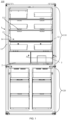
- the refrigerator 100 includes a refrigerator body 1, a drawer seat 2, a drawer body 3, at least one modified atmosphere film assembly 7, and a gas suction device 8.
- the refrigerator body 1 includes a left side wall 11, a right side wall 12, and a rear side wall 13.
- the refrigerator 100 may further include a door body, and the door body is mounted on a side of the refrigerator body 1 opposite to the rear side wall 13.
- the refrigerator body 1 has a low temperature storage space 14, and the low temperature storage space 14 may be a refrigerating compartment 110 or a freezing compartment 120.
- the drawer seat 2 is disposed in the low temperature storage space 14. An end of the drawer seat 2 away from the rear side wall 13 of the refrigerator body 1 is provided with an opening, and the drawer seat 2 is hollow.
- the drawer body 3 has a front side, a rear side, a left side, and a right side.
- the front side refers to a side of the drawer body 3 away from the rear side wall 13 of the refrigerator body 1
- the rear side is a side of the drawer body 3 corresponding to the rear side wall 13 of the refrigerator body 1
- the left side is a side of the drawer body 3 corresponding to the left side wall 11 of the refrigerator body 1
- the right side is a side of the drawer body 3 corresponding to the right side wall 11 of the refrigerator body 1.
- the drawer body 3 has a storage cavity 4 and is mounted in the drawer seat 2.
- a mounting cavity 5 and a return cavity 6 that communicate with each other are defined between the drawer body 3 and the drawer seat 2, and the mounting cavity 5 and the return cavity 6 are provided on different sides of the drawer body 3 respectively.
- the mounting cavity 5 and the return cavity 6 are disposed at different sides of the rear side, the left side and the right side of the drawer body 3 respectively, and are in communication with the storage cavity 4, respectively.
- the modified atmosphere film assembly 7 is disposed in the mounting cavity 5, and the permeability of the modified atmosphere film assembly 7 to oxygen is greater than a permeability to nitrogen. That is, the modified atmosphere film assembly 7 allows the oxygen in the air to pass more than the nitrogen, and may block at least a part of the nitrogen in the air. For example, the modified atmosphere film assembly 7 allows more than 80% of the oxygen in the air to pass through the modified atmosphere film assembly 7, and blocks more than 80% of the nitrogen in the air. For another example, the modified atmosphere film assembly 7 allows 100% of the oxygen in the air to pass through the modified atmosphere film assembly 7, and blocks 100% of the nitrogen in the air.
- the gas suction device 8 is disposed in the low temperature storage space 14 and is configured to extract and suck the air in the modified atmosphere film assembly 7, so as to make the air in the storage cavity 4 enter the mounting cavity 5, the air passes through the modified atmosphere film assembly 7 in the mounting cavity 5 is removed with oxygen, and then flows back into the storage cavity 4 through the return cavity 6.
- the gas suction device 8 includes an air suction pump.
- the storage cavity 4 of the drawer body 3 is used for storing food, and the air in the storage cavity 4 enters the mounting cavity 5 due to the suction of the gas suction device 8.
- the modified atmosphere film assembly 7 allows the oxygen in the air to pass more than nitrogen, and may block at least a part of the nitrogen in the air. Therefore, the gas suction device 8 may suck the gas rich in oxygen and poor in nitrogen, so that the gas blocked in the mounting cavity 5 is a nitrogen-enriched gas. Then, the nitrogen-enriched gas flows back to the storage cavity 4 through the return cavity 6, so that the air in the drawer seat 2 is deoxygenated and filtered by means of circulation flow.
- the circulation flow of air covers many regions of the storage cavity 4, which greatly improves the efficiency of gas regulation and reduces the intensity of aerobic respiration of fruits and vegetables, thereby achieving the purpose of preservation of fruits and vegetables for a long time.
- the mounting cavity 5 is disposed at a side of the drawer body 3 proximate to the rear side wall 13 of the refrigerator body 1, and the return cavity 6 is disposed at the left and/or right side of the drawer body 3.
- FIG. 2 exemplifies that the return cavities 6 are disposed at the left side and the right side of the drawer body 3.
- the modified atmosphere film assembly 7 in the mounting cavity 5 is disposed at the rear side of the drawer body 3, which may effectively reduce the space occupied by the drawer seat 2 in the vertical direction, so as to make the overall structure of the refrigerator 100 more compact and reliable, and facilitate the rapid maintenance and replacement of the modified atmosphere film assembly 7.
- the gas suction device 8 may be directly mounted on a back of an outer side of the mounting cavity 5, that is, the gas suction device 8 is mounted in the low temperature storage space 14 between the mounting cavity 5 and the rear side wall 13 of the refrigerator body 1, and does not need to be mounted in the compressor chamber, the foamed layer, and the top of the refrigerator body 1, so that problems such as difficulty in heat dissipation, resonance with the compressor, excessively long pipelines, and affecting refrigeration may be avoided, and the compact mounting between the gas suction device 8 and the modified atmosphere film assembly 7 may be implemented, which has advantages of reducing the length of the pipeline, effectively isolating the noise after closing the door, and being prone to install and replace.
- the return cavities 6 are disposed at the left side and the right side of the drawer body 3, so as to form two gas circulation flow loops, so that the efficiency of gas regulation is high.
- the return cavity 6 may further be disposed at the left side or the right side of the drawer body 3 separately, and only one gas circulation flow loop is used to implement gas regulation, thereby saving internal space.
- the drawer body 3 includes: a front panel 31, a rear side plate 34, a left side plate 32, and a right side plate 32.
- a first vent 35 is provided at an end of side plate of the left side plate 32 or the right side plate 32 of the drawer body 3 provided with the return cavity 6 on a side away from the mounting cavity 5.
- the end of the left side plate 32 away from the mounting cavity 5 is provided with the first vent 35; if a side of the right side plate 32 is provided with the return cavity 6, the end of the right side plate 32 away from the mounting cavity 5 is provided with the first vent 35; if a side of the left side plate 32 and a side of the right side plate 32 are provided with the return cavity 6 respectively, the ends of the left side plate 32 and the right side plate 32 away from the mounting cavity 5 are provided with the first vent 35.
- the first vent 35 is configured to communicate with the storage cavity 4 and the return cavity 6.
- the air filtered and regulated by the modified atmosphere film assembly 7 flows to the return cavity 6 disposed at the left and/or right side of the drawer seat 2 from the mounting cavity 5, and finally return to the storage cavity 4 from the return cavity 6, so as to form a gas circulation flow loop.
- the gas flows from the front side to the rear side of the storage cavity 4, covering the entire storage cavity 4, serving to transfer heat, improving the uniformity of the temperature in the storage cavity 4, and improving the cooling effect.
- the efficiency of gas regulation may be improved, and the fruits and vegetables stored in the storage cavity 4 are all in a nitrogen-rich and oxygen-poor gas environment, thereby effectively inhibiting the aerobic respiration and metabolic reactions of the fruits and vegetables.
- the first vent 35 may be provided in any shape.
- the shape of the first vent 35 may be a circle, an ellipse, a rectangle or a polygon, and the present disclosure is not limited thereto.
- the first vent 35 is formed by a plurality of small holes distributed in an array.
- FIGS. 3 and 6 show an example in which the first vent 35 is formed by the plurality of small holes distributed in an array, so as to reduce the risk of contamination caused by the items in the storage cavity 4 entering the return cavity 6 while ensuring the ventilation volume.
- the modified atmosphere film assembly 7 includes a mounting frame 71 and two modified atmosphere films 72.
- the mounting frame 71 is connected to the drawer seat 2.
- the two modified atmosphere films 72 are disposed at two sides of the mounting frame 71 in a direction L1 perpendicular to a plane defined by the mounting frame respectively. That is, the two modified atmosphere films 72 are disposed at the front side and the rear side of the mounting frame 71 respectively, and the two modified atmosphere films 72 and the mounting frame 71 define the oxygen-enriched gas accommodating cavity 10.
- a suction port 81 of the gas suction device 8 communicates with the oxygen-enriched gas accommodating cavity 10.
- the mounting frame 71 is provided with a gas outlet 711 leading to the oxygen-enriched gas accommodating cavity 10.
- the suction port 81 of the gas suction device 8 is connected to the gas outlet 711 through the pipe 9.
- the air in the mounting cavity 5 passes through the modified atmosphere films 72 on two sides of the mounting frame 71, so as to form an oxygen-enriched gas due to the guidance of the suction port 81.
- the oxygen-enriched gas enters the oxygen-enriched gas accommodating cavity 10, and is discharged to the outside of the refrigerator body 1 through an exhaust port 82 of the gas suction device 8, so that the effect of oxygen removal filtration is implemented, and the nitrogen-enriched gas is blocked and made to flow back into the storage cavity 4 from the return cavity 6.
- an orthogonal projection of an outer contour of the mounting frame 71 on the rear side wall 13 of the refrigerator body 1 is approximately in a geometric shape of such as a rectangle, a circle, or a triangle, and the present disclosure is not limited thereto.
- the mounting frame 71 is provided with a plurality of reinforcing ribs 73 therein.
- Each reinforcing rib 73 supports the mounting frame 71, and strengthens the structural strength of the mounting frame 71, so as to improve the stability of the oxygen-enriched gas accommodating cavity 10.
- the plurality of reinforcing ribs 73 includes a plurality of first reinforcing ribs 731 and a plurality of second reinforcing ribs 732.
- the plurality of first reinforcing ribs 731 and the plurality of second reinforcing ribs 732 intersect each other, and divide the oxygen-enriched gas accommodating cavity 10 into a plurality of cavities 101.
- a through hole 733 is provided in the first reinforcing rib 731 or the second reinforcing rib 732 between any two adjacent cavities 101.
- each reinforcing rib 73 supports the mounting frame 71 and the modified atmosphere films 72 on the front and rear sides of the mounting frame 71, which further improves the stability of the oxygen-enriched gas accommodating cavity 10.
- the modified atmosphere film assembly 7 further includes a first support plate 74 and a second support plate 75.
- the first support plate 74 is disposed at a side of one modified atmosphere film 72 of the two modified atmosphere films 72 away from the mounting frame 71
- the second support plate 75 is disposed at a side of another modified atmosphere film 72 of the two modified atmosphere films 72 away from the mounting frame 71.
- the first support plate 74 and the second support plate 75 are provided with a plurality of hollow regions 76.
- the gas may enter the oxygen-enriched gas accommodating cavity 10 from the plurality of hollow regions 76. Due to the action of the first support plate 74 and the second support plate 75, the amount of deformation caused to the modified atmosphere film 72 by the force generated by the gas flow may be reduced, and the service life of the modified atmosphere film 72 may be prolonged.
- the fixing manner of the first support plate 74 and the second support plate 75 are fixed in a non-exclusive manner.
- the first support plate 74 and the second support plate 75 are clamped with each together. With such arrangement, the first support plate 74 and the second support plate 75 are easily assembled and disassembled to facilitate maintenance.
- the first support plate 74 and the second support plate 75 are clamped with each together, so that the modified atmosphere film 72 may be simultaneously fixed on the mounting frame 71.
- the first support plate 74 is provided with a plurality of first elastic claws 741 and a plurality of first clamping grooves 742, and the plurality of first elastic claws 741 and the plurality of first clamping grooves 742 are alternately distributed in a circumferential direction of the first support plate 74.
- the second support plate 75 is provided with a plurality of second elastic claws 751 and a plurality of second clamping grooves 752, and the plurality of second elastic claws 751 and the plurality of second clamping grooves 752 are alternately distributed in a circumferential direction of the second support plate 75.
- the plurality of first elastic claws 741 are clamped with the plurality of second clamping grooves 752 in one-to-one correspondence
- the plurality of second elastic claws 751 are clamped with the plurality of first clamping grooves 742 in one-to-one correspondence.
- the refrigerator 100 includes a plurality of modified atmosphere film assemblies 7, and orthogonal projections of the plurality of modified atmosphere film assemblies 7 on the rear side wall 13 of the refrigerator body 1 are not overlapped with each other.
- the plurality of modified atmosphere film assemblies 7 in the mounting cavity 5 may perform oxygen removal filtration simultaneously, thereby improving the efficiency of gas regulation.
- the refrigerator 100 further includes a connecting pipe 20, the connecting pipe 20 communicates with each modified atmosphere film assembly 7, and the suction port 81 of the gas suction device 8 communicates with the connecting pipe 20.
- the gas suction device 8 may simultaneously discharge the oxygen-enriched gas in the plurality of oxygen-enriched gas accommodating cavities 10, and a number of gas suction devices 8 may be reduced.
- the gas suction device 8 may include a vacuum pump, and may be mounted on an outer back of the air extraction cavity, and does not need to be mounted in the compressor chamber, the foamed layer, and the top of the refrigerator body 1.
- the suction port 81 of the gas suction device 8 is communicated with the plurality of oxygen-enriched gas accommodating cavities 10 through the connecting pipe 20.
- the remaining modified atmosphere film assemblies 7 may continue to regulate the gas, and has better stability.
- FIGS. 2 and 5 there are two modified atmosphere film assemblies 7, which are distributed left and right in the horizontal direction in the mounting cavity 5.
- the two oxygen-enriched gas accommodating cavities 10 are connected to each other through the connecting pipe 20. That is, the gas outlets 711 on the two mounting frames 71 are connected to each other through the connecting pipe 20, and the suction port 81 of the gas suction device 8 is communicated with the connecting pipe 20, so as to form two gas circulation flow loops.
- Each gas circulation flow loop may be operated separately. In a case where the failure of components, leakage or blockage of channel occurs in one of the gas circulation flow loops, another gas circulation flow loop may continue to regulate the gas with better stability.
- the refrigerator 100 further includes a fixing plate 21.
- the fixing plate 21 is connected to the drawer seat 2 and is disposed in the mounting cavity 5.
- the mounting cavity 5 is divided into a front cavity 51 and a rear cavity 52 by the fixing plate 21.
- the fixing plate 21 and the rear side plate 34 of the drawer body 3 define the front cavity 51
- the fixing plate 21 and the rear side plate of the drawer seat 2 define the rear cavity 52.
- the rear side plate of the drawer seat 2 refers to a plate of the drawer seat 2 proximate to the rear side wall 13 of the refrigerator body 1.
- the rear cavity 52 is communicated with the return cavity 6
- the modified atmosphere film assembly 7 is disposed in the rear cavity 52
- the fixing plate 21 is provided with a second vent 211 that communicates the front cavity 51 with the rear cavity 52.
- the modified atmosphere film assembly 7 is disposed in the rear cavity 52, so as to avoid contamination caused by contact with the items in the storage cavity 4.
- the contact between the modified atmosphere film assembly 7 and the vegetable leaves, soil, water droplets or plastic films in the storage cavity 4 may be avoided, and the service life of the modified atmosphere film 72 may be prolonged.
- the orthogonal projection of the outer contour of the mounting frame 71 on the rear side wall 13 of the refrigerator body 1 is approximately a rectangle.
- the rear side of the fixing plate 21 is provided with a fixing member 22 corresponding to the four corners of each mounting frame 71.
- the fixing member 22 includes a base 221, a first clamping board 222 and a second clamping board 223. The edges of the four corners of the mounting frame 71 abut against the corresponding first clamping boards and second clamping boards 223 of the fixing member 22, so that the mounting frame 71 is clamped between the four fixing members 22.
- the base 221 is located between the mounting frame 71 and the fixing plate 21, and is configured to define a distance between the mounting frame 71 and the fixing plate 21. With such arrangement, the mounting frame 71 and the fixing plate 21 are easily assembled and disassembled, and is easily replaced.
- the return cavities 6 are disposed at the left side and right side of the drawer body 3.
- the second vent 211 is disposed in the middle of the fixing plate 21.
- the left side and the right side of the fixing plate 21 are provided with at least one third vent 212 respectively.
- the third vent 212 disposed at the left side of the fixing plate 21 is configured to communicate with the rear cavity 52 and the return cavity 6 disposed at the left side of the drawer body 3.
- the third vent 212 disposed at the right side of the fixing plate 21 is configured to communicate with the rear cavity 52 and the return cavity 6 disposed at the right side of the drawer body 3.
- the refrigerator 100 further includes an air guide loop 23, and the air guide loop 23 is disposed between the fixing plate 21 and the rear side plate 34 of the drawer body 3.
- the air guide loop 23 may be disposed on the fixing plate 21 or the rear side plate 34 of the drawer body 3, and FIG. 3 and FIG. 7 illustrate that the air guide loop 23 is disposed on the fixing plate.
- a fourth vent 341 is provided on the rear side plate 34 of the drawer body 3. An end of the air guide loop 23 is communicated with the second vent 211, and another end of the air guide loop 23 is communicated with the fourth vent 341. In this way, referring to FIGS.
- the air guide loop 23 abuts against the rear side plate 34 of the drawer body 3, so as to form an air flow channel, facilitating the air in the storage cavity 4 to directly enter the rear cavity 52 through the air guide loop 23, accelerating the gas circulation flow, and improving the efficiency of gas regulation.
- the refrigerator 100 further includes an elastic pad.
- the elastic pad is disposed between the air guide loop and the rear side plate of the drawer body 3, so as to play a role of shock absorption, noise reduction and protection.
- the elastic pad is disposed between the air guide loop and the fixing plate, so as to play the role of shock absorption, noise reduction and protection.
- the elastic pad includes a silicone pad.
- the second vent 211, the third vent 212 and the fourth vent 341 may be provided in any shape.
- the shapes of the second vent 211, the third vent 212 and the fourth vent 341 are circles, ovals, rectangles or polygons, and the present disclosure is not limited thereto.
- the second vent 211, the third vent 212 and the fourth vent 341 are all formed by a plurality of small holes distributed in an array.
- FIGS. 5 and 6 are illustrated by taking an example in which the second vent 211 and the fourth vent 341 are formed by the plurality of small holes distributed in an array.
- FIG. 7 is illustrated by taking an example in which the third vents 212 are rectangular notches formed on the left and right sides of the fixing plate 21.
- the refrigerator 100 further includes at least one fan 24 disposed in the rear cavity 52.
- Each fan 24 includes an air inlet and an air outlet, the air inlet is located on the axis of the fan 24, and the air inlet communicates with the second vent 211.
- the air outlet is located on a peripheral side of the fan 24, and the air outlet faces one or more modified atmosphere film assemblies 7.
- the fan 29 guides the air to flow to the modified atmosphere film assembly 7, so as to accelerate the air flow and improve the efficiency of gas regulation.
- the modified atmosphere film assemblies 7 are distributed in the horizontal direction in the mounting cavity 5
- the rear side of the fixing plate 21 is provided with a connecting column 30, and the fan 24 is mounted on the rear side of the fixing plate 21 through the connecting column 30.
- the two fans 24 are distributed up and down in the vertical direction.
- one fan 24 guides the air flow to the modified atmosphere film assembly 7 located on the left side
- another fan 24 guides the air flow to the modified atmosphere film assembly 7 located on the right side, so that the gas flow speed may be accelerated, and the air may be guided to flow to the two gas circulation flow loops respectively, thereby accelerating the gas circulation flow and improving the efficiency of gas regulation.
- each gas circulation flow loop includes: storage cavity 4 ⁇ fourth vent 341 ⁇ air guide loop 23 ⁇ second vent 211 ⁇ fan 24 ⁇ modified atmosphere film assembly 7 ⁇ return cavity 6 ⁇ first vent 35 ⁇ storage cavity 4.
- the operating principle includes: the fan 24 blows the air inside the storage cavity 4 to the modified atmosphere film assembly 7, and the gas suction device 8 performs suction to make the air pass through the modified atmosphere film 72.
- the oxygen permeates through the modified atmosphere film 72 more than the nitrogen, so as to gradually reduce the oxygen concentration in the mounting cavity 5.
- the nitrogen-enriched gas in the mounting cavity 5 returns to the storage cavity 4 through the return cavity 6 to form a low-oxygen preservation space, so as to inhibit the respiration and metabolic reaction of the fruits and vegetables stored in the drawer body 3, thereby implementing the purpose of prolonging the fresh-keeping time.
- the refrigerator 100 further includes a sealing loop 25.
- the sealing loop 25 is disposed at the end of the drawer body 3 away from the rear side plate of the drawer seat 2, that is, the front panel 31 of the drawer body 3.
- the sealing loop 25 cooperates with the opening located at the end of the drawer seat 2 away from the rear side wall 13 of the refrigerator body 1, so as to implement the sealing of the drawer seat 2.
- a negative pressure phenomenon may be generated in the drawer seat 2.
- the sealing loop 25 allows outside air to enter the drawer seat 2. That is, in a case where the negative pressure value in the drawer seat 2 is less than the preset value, the interior of the drawer seat 2 is isolated from the outside air, and the negative pressure value in the drawer seat 2 increases continuously due to the action of the gas suction device 8.
- the interior of the drawer seat 2 is communicated with the outside air, so that the user may conveniently open the drawer body 3 and the fruits and vegetables may be prevented from anaerobic respiration.
- the preset value may be a negative pressure value corresponding to a first gas atmosphere
- the first gas atmosphere includes a gas atmosphere that is conducive to the preservation of the fruits and vegetables.
- the first gas atmosphere includes a gas environment corresponding to only guaranteeing the basic respiration of fruits and vegetables, so as to reduce the intensity of aerobic respiration of fruits and vegetables, and simultaneously prevent the anaerobic respiration of fruits and vegetables.
- the refrigerator 100 further includes a cooling air duct 26, and the cooling air duct 26 is disposed at a top of the drawer seat 2, so as to cool the storage cavity 4 indirectly.
- the top of the drawer seat 2 is an end of the drawer seat 2 that is proximate to the top of the refrigerator body 1.
- the low temperature environment formed by the cooling air duct may reduce the risk of overheating of the gas suction device 8, and protect the gas suction device 8, thereby facilitating the efficient operation of the gas suction device 8 and prolonging the service life of the gas suction device 8.
- a surface of a top plate (i.e., a plate located on top of the drawer seat 2 in the drawer seat 2) of the drawer seat 2 away from the drawer body 3 is provided with an air groove 261.
- the refrigerator 100 further includes an air duct cover plate 262.
- the air duct cover plate 262 is embedded in the surface of the top plate of the drawer seat 2 away from the drawer body 3, and defines the cooling air duct 26 with the air groove 261. In this case, since the air duct cover plate 262 is embedded in the surface of the top plate of the drawer seat 2 away from the drawer body 3, the mounting space in the vertical direction of the refrigerator 100 may not be affected.
- the modified atmosphere film assembly 7 is disposed at the rear side of the drawer body 2, which does not affect the provision of the cooling air duct 26 on the top plate of the drawer seat 2.
- the drawer seat 2 and the drawer body 3 may be disposed in the refrigerating compartment 110 of the refrigerator 100, and a cooling vent 111 provided at a back of the refrigerating compartment 110 is communicated to the cooling air duct 26 correspondingly.
- the cooling air duct 26 is used to cool the drawer seat 2 indirectly, which can effectively prevent the fruits and vegetables from withering and drying due to the direct blowing of cold air, retain the crisp and tender taste and texture of the fruits and vegetables.
- the oxygen concentration in the drawer body 3 is lower than the oxygen concentration in the refrigerating compartment 110, which may inhibit the respiration and metabolism of fruits and vegetables, reduce the occurrence of oxidative browning, and prevent the loss of nutrients and food deterioration. Therefore, the preservation period of stored food may be prolonged.
- the air groove 261 may be a U-shaped groove disposed on the top plate of the drawer seat 2.
- the air duct cover plate 262 is disposed on the U-shaped groove by means of hooks and fixing screws, so as to form the cooling air duct 26.
- the cooling air may enter the U-shaped groove from an end of the U-shaped groove and exit the U-shaped groove from another end of the U-shaped groove. It can be understood that, the U-shaped cooling air duct may increase the cooling area, so as to ensure the cooling efficiency.
- guide structures 27 for matching and guiding is provided between the drawer body 3 and the drawer seat 2.
- the guide structures 27 are located on the left and right sides of the drawer body 3, so as to implement the pulling function of the drawer body 3.
- the guide structures 27 may be disposed in the return cavity 6.
- the drawer body 3 is provided with a locking structure 28, and the locking structure 28 is configured to be able to be clamped with the drawer seat 2. Exemplarily, after the drawer body 3 is closed, the locking structure 28 is clamped on the drawer seat 2, so as to maintain a relatively sealed state.
Landscapes
- Engineering & Computer Science (AREA)
- Chemical & Material Sciences (AREA)
- Combustion & Propulsion (AREA)
- Physics & Mathematics (AREA)
- Mechanical Engineering (AREA)
- Thermal Sciences (AREA)
- General Engineering & Computer Science (AREA)
- Cold Air Circulating Systems And Constructional Details In Refrigerators (AREA)
- Separation Using Semi-Permeable Membranes (AREA)
- Devices That Are Associated With Refrigeration Equipment (AREA)
Applications Claiming Priority (2)
| Application Number | Priority Date | Filing Date | Title |
|---|---|---|---|
| CN202010385574.0A CN111637672B (zh) | 2020-05-08 | 2020-05-08 | 一种冰箱 |
| PCT/CN2020/141732 WO2021223455A1 (fr) | 2020-05-08 | 2020-12-30 | Réfrigérateur |
Publications (3)
| Publication Number | Publication Date |
|---|---|
| EP4148349A1 true EP4148349A1 (fr) | 2023-03-15 |
| EP4148349A4 EP4148349A4 (fr) | 2024-06-05 |
| EP4148349B1 EP4148349B1 (fr) | 2025-09-10 |
Family
ID=72330844
Family Applications (1)
| Application Number | Title | Priority Date | Filing Date |
|---|---|---|---|
| EP20934745.9A Active EP4148349B1 (fr) | 2020-05-08 | 2020-12-30 | Réfrigérateur |
Country Status (4)
| Country | Link |
|---|---|
| EP (1) | EP4148349B1 (fr) |
| JP (1) | JP7473682B2 (fr) |
| CN (1) | CN111637672B (fr) |
| WO (1) | WO2021223455A1 (fr) |
Families Citing this family (4)
| Publication number | Priority date | Publication date | Assignee | Title |
|---|---|---|---|---|
| CN111637672B (zh) * | 2020-05-08 | 2021-11-19 | 海信容声(广东)冰箱有限公司 | 一种冰箱 |
| CN113137812B (zh) * | 2021-04-28 | 2022-08-23 | 珠海格力电器股份有限公司 | 冰箱控制方法及冰箱 |
| CN117109223B (zh) * | 2023-10-25 | 2023-12-22 | 贵州健易测科技有限公司 | 一种农产品冷藏温湿度调控装置及温湿度调控方法 |
| CN118274534B (zh) * | 2024-06-03 | 2024-08-06 | 宁波惠康工业科技股份有限公司 | 一种动态减震冷藏箱 |
Family Cites Families (20)
| Publication number | Priority date | Publication date | Assignee | Title |
|---|---|---|---|---|
| JPH055585A (ja) * | 1991-06-28 | 1993-01-14 | Sharp Corp | 新鮮貯蔵庫 |
| JPH0759511A (ja) * | 1993-08-23 | 1995-03-07 | Matsushita Refrig Co Ltd | 貯蔵庫 |
| JP2009174725A (ja) | 2008-01-22 | 2009-08-06 | Hitachi Appliances Inc | 冷蔵庫 |
| CN201199115Y (zh) * | 2008-04-10 | 2009-02-25 | 河南新飞电器有限公司 | 一种降氧气调保鲜冰箱 |
| WO2014049739A1 (fr) | 2012-09-26 | 2014-04-03 | 日立アプライアンス株式会社 | Réfrigérateur |
| CN103090613A (zh) * | 2012-10-24 | 2013-05-08 | 徐东明 | 一种保鲜冰箱 |
| CN103575050A (zh) * | 2013-11-15 | 2014-02-12 | 海信容声(广东)冰箱有限公司 | 一种氮气保鲜抽屉 |
| CN206131588U (zh) * | 2016-09-05 | 2017-04-26 | 合肥海尔电冰箱有限公司 | 冷藏冷冻装置 |
| CN106524645A (zh) | 2016-12-02 | 2017-03-22 | 青岛海尔股份有限公司 | 冷藏冷冻设备 |
| CN106642913B (zh) * | 2016-12-02 | 2020-06-23 | 青岛海尔股份有限公司 | 冷藏冷冻装置 |
| CN107044752B (zh) | 2016-12-02 | 2019-12-24 | 青岛海尔股份有限公司 | 冰箱 |
| CN206362061U (zh) * | 2016-12-02 | 2017-07-28 | 青岛海尔股份有限公司 | 冷藏冷冻装置 |
| CN207214619U (zh) * | 2017-06-09 | 2018-04-10 | 合肥华凌股份有限公司 | 冷藏抽屉及冷藏装置 |
| CN207065960U (zh) * | 2017-06-12 | 2018-03-02 | 江西天禄科技集团有限公司 | 一种贵重药物保存柜 |
| JP2019074273A (ja) | 2017-10-17 | 2019-05-16 | 東芝ライフスタイル株式会社 | 冷蔵庫 |
| CN108332479B (zh) * | 2017-12-22 | 2021-05-25 | 重庆海尔制冷电器有限公司 | 冰箱 |
| JP6986482B2 (ja) | 2018-04-09 | 2021-12-22 | 東芝ライフスタイル株式会社 | 貯蔵庫 |
| CN209744805U (zh) * | 2018-12-21 | 2019-12-06 | 青岛海尔股份有限公司 | 冷藏冷冻装置 |
| CN110425816A (zh) * | 2019-08-01 | 2019-11-08 | 安徽冠东科技有限公司 | 一种排出乙烯气体式果蔬低压保鲜设备 |
| CN111637672B (zh) * | 2020-05-08 | 2021-11-19 | 海信容声(广东)冰箱有限公司 | 一种冰箱 |
-
2020
- 2020-05-08 CN CN202010385574.0A patent/CN111637672B/zh active Active
- 2020-12-30 JP JP2022564354A patent/JP7473682B2/ja active Active
- 2020-12-30 WO PCT/CN2020/141732 patent/WO2021223455A1/fr not_active Ceased
- 2020-12-30 EP EP20934745.9A patent/EP4148349B1/fr active Active
Also Published As
| Publication number | Publication date |
|---|---|
| CN111637672B (zh) | 2021-11-19 |
| EP4148349B1 (fr) | 2025-09-10 |
| JP7473682B2 (ja) | 2024-04-23 |
| JP2023523732A (ja) | 2023-06-07 |
| EP4148349A4 (fr) | 2024-06-05 |
| WO2021223455A1 (fr) | 2021-11-11 |
| CN111637672A (zh) | 2020-09-08 |
Similar Documents
| Publication | Publication Date | Title |
|---|---|---|
| EP4148349A1 (fr) | Réfrigérateur | |
| EP3550231B1 (fr) | Ensemble tiroir et dispositif de réfrigération et de congélation avec un ensemble tiroir | |
| RU2733617C2 (ru) | Холодильник | |
| KR20190083340A (ko) | 공기 분리 장치와 냉장 냉동 장치 | |
| WO2018103722A1 (fr) | Dispositif de réfrigération et de congélation | |
| CN115111841A (zh) | 冷藏冷冻设备 | |
| WO2018099460A1 (fr) | Ensemble pompe d'extraction d'air et dispositif de réfrigération et de congélation | |
| CN106582216B (zh) | 空气分离装置和冷藏冷冻装置 | |
| JPH05227881A (ja) | 保存庫 | |
| CN113639507A (zh) | 冷藏冷冻设备 | |
| WO2018161918A1 (fr) | Dispositif de réfrigération et de congélation et son ensemble tiroir | |
| EP3550228B1 (fr) | Dispositif de réfrigération et de congélation | |
| CN108302862A (zh) | 冷藏冷冻装置 | |
| CN106766553B (zh) | 冰箱及用于冰箱的储物容器组件 | |
| CN212006418U (zh) | 一种冰箱 | |
| CN206291583U (zh) | 冷藏冷冻装置 | |
| CN106679278B (zh) | 冷藏冷冻装置 | |
| CN113294964B (zh) | 一种冰箱 | |
| CN220771497U (zh) | 冰箱 | |
| WO2018099412A1 (fr) | Dispositif de réfrigération et de congélation | |
| WO2021098784A1 (fr) | Réfrigérateur | |
| CN106642916A (zh) | 冷藏冷冻装置 | |
| CN206449968U (zh) | 冷藏冷冻装置 | |
| CN206449966U (zh) | 冷藏冷冻装置 | |
| CN107062733B (zh) | 冰箱及用于冰箱的储物容器 |
Legal Events
| Date | Code | Title | Description |
|---|---|---|---|
| STAA | Information on the status of an ep patent application or granted ep patent |
Free format text: STATUS: THE INTERNATIONAL PUBLICATION HAS BEEN MADE |
|
| PUAI | Public reference made under article 153(3) epc to a published international application that has entered the european phase |
Free format text: ORIGINAL CODE: 0009012 |
|
| STAA | Information on the status of an ep patent application or granted ep patent |
Free format text: STATUS: REQUEST FOR EXAMINATION WAS MADE |
|
| 17P | Request for examination filed |
Effective date: 20221017 |
|
| AK | Designated contracting states |
Kind code of ref document: A1 Designated state(s): AL AT BE BG CH CY CZ DE DK EE ES FI FR GB GR HR HU IE IS IT LI LT LU LV MC MK MT NL NO PL PT RO RS SE SI SK SM TR |
|
| DAV | Request for validation of the european patent (deleted) | ||
| DAX | Request for extension of the european patent (deleted) | ||
| A4 | Supplementary search report drawn up and despatched |
Effective date: 20240507 |
|
| RIC1 | Information provided on ipc code assigned before grant |
Ipc: F25D 25/02 20060101ALI20240501BHEP Ipc: F25D 17/06 20060101ALI20240501BHEP Ipc: F25D 17/04 20060101ALI20240501BHEP Ipc: F25D 11/00 20060101AFI20240501BHEP |
|
| GRAP | Despatch of communication of intention to grant a patent |
Free format text: ORIGINAL CODE: EPIDOSNIGR1 |
|
| STAA | Information on the status of an ep patent application or granted ep patent |
Free format text: STATUS: GRANT OF PATENT IS INTENDED |
|
| GRAS | Grant fee paid |
Free format text: ORIGINAL CODE: EPIDOSNIGR3 |
|
| INTG | Intention to grant announced |
Effective date: 20250704 |
|
| GRAA | (expected) grant |
Free format text: ORIGINAL CODE: 0009210 |
|
| STAA | Information on the status of an ep patent application or granted ep patent |
Free format text: STATUS: THE PATENT HAS BEEN GRANTED |
|
| AK | Designated contracting states |
Kind code of ref document: B1 Designated state(s): AL AT BE BG CH CY CZ DE DK EE ES FI FR GB GR HR HU IE IS IT LI LT LU LV MC MK MT NL NO PL PT RO RS SE SI SK SM TR |
|
| REG | Reference to a national code |
Ref country code: GB Ref legal event code: FG4D |
|
| REG | Reference to a national code |
Ref country code: CH Ref legal event code: EP |
|
| REG | Reference to a national code |
Ref country code: DE Ref legal event code: R096 Ref document number: 602020058771 Country of ref document: DE |
|
| REG | Reference to a national code |
Ref country code: IE Ref legal event code: FG4D |
|
| PGFP | Annual fee paid to national office [announced via postgrant information from national office to epo] |
Ref country code: DE Payment date: 20251211 Year of fee payment: 6 |
|
| PGFP | Annual fee paid to national office [announced via postgrant information from national office to epo] |
Ref country code: GB Payment date: 20251219 Year of fee payment: 6 |
|
| PG25 | Lapsed in a contracting state [announced via postgrant information from national office to epo] |
Ref country code: NO Free format text: LAPSE BECAUSE OF FAILURE TO SUBMIT A TRANSLATION OF THE DESCRIPTION OR TO PAY THE FEE WITHIN THE PRESCRIBED TIME-LIMIT Effective date: 20251210 |
|
| REG | Reference to a national code |
Ref country code: LT Ref legal event code: MG9D |
|
| PG25 | Lapsed in a contracting state [announced via postgrant information from national office to epo] |
Ref country code: FI Free format text: LAPSE BECAUSE OF FAILURE TO SUBMIT A TRANSLATION OF THE DESCRIPTION OR TO PAY THE FEE WITHIN THE PRESCRIBED TIME-LIMIT Effective date: 20250910 |
|
| REG | Reference to a national code |
Ref country code: NL Ref legal event code: MP Effective date: 20250910 |
|
| PG25 | Lapsed in a contracting state [announced via postgrant information from national office to epo] |
Ref country code: HR Free format text: LAPSE BECAUSE OF FAILURE TO SUBMIT A TRANSLATION OF THE DESCRIPTION OR TO PAY THE FEE WITHIN THE PRESCRIBED TIME-LIMIT Effective date: 20250910 |
|
| PGFP | Annual fee paid to national office [announced via postgrant information from national office to epo] |
Ref country code: FR Payment date: 20251229 Year of fee payment: 6 |
|
| PG25 | Lapsed in a contracting state [announced via postgrant information from national office to epo] |
Ref country code: GR Free format text: LAPSE BECAUSE OF FAILURE TO SUBMIT A TRANSLATION OF THE DESCRIPTION OR TO PAY THE FEE WITHIN THE PRESCRIBED TIME-LIMIT Effective date: 20251211 |
|
| PG25 | Lapsed in a contracting state [announced via postgrant information from national office to epo] |
Ref country code: SE Free format text: LAPSE BECAUSE OF FAILURE TO SUBMIT A TRANSLATION OF THE DESCRIPTION OR TO PAY THE FEE WITHIN THE PRESCRIBED TIME-LIMIT Effective date: 20250910 |
|
| PG25 | Lapsed in a contracting state [announced via postgrant information from national office to epo] |
Ref country code: LV Free format text: LAPSE BECAUSE OF FAILURE TO SUBMIT A TRANSLATION OF THE DESCRIPTION OR TO PAY THE FEE WITHIN THE PRESCRIBED TIME-LIMIT Effective date: 20250910 |
|
| PG25 | Lapsed in a contracting state [announced via postgrant information from national office to epo] |
Ref country code: PL Free format text: LAPSE BECAUSE OF FAILURE TO SUBMIT A TRANSLATION OF THE DESCRIPTION OR TO PAY THE FEE WITHIN THE PRESCRIBED TIME-LIMIT Effective date: 20250910 Ref country code: BG Free format text: LAPSE BECAUSE OF FAILURE TO SUBMIT A TRANSLATION OF THE DESCRIPTION OR TO PAY THE FEE WITHIN THE PRESCRIBED TIME-LIMIT Effective date: 20250910 |
|
| PG25 | Lapsed in a contracting state [announced via postgrant information from national office to epo] |
Ref country code: RS Free format text: LAPSE BECAUSE OF FAILURE TO SUBMIT A TRANSLATION OF THE DESCRIPTION OR TO PAY THE FEE WITHIN THE PRESCRIBED TIME-LIMIT Effective date: 20251210 |
|
| PG25 | Lapsed in a contracting state [announced via postgrant information from national office to epo] |
Ref country code: ES Free format text: LAPSE BECAUSE OF FAILURE TO SUBMIT A TRANSLATION OF THE DESCRIPTION OR TO PAY THE FEE WITHIN THE PRESCRIBED TIME-LIMIT Effective date: 20250910 |
|
| REG | Reference to a national code |
Ref country code: AT Ref legal event code: MK05 Ref document number: 1836270 Country of ref document: AT Kind code of ref document: T Effective date: 20250910 |
|
| PG25 | Lapsed in a contracting state [announced via postgrant information from national office to epo] |
Ref country code: NL Free format text: LAPSE BECAUSE OF FAILURE TO SUBMIT A TRANSLATION OF THE DESCRIPTION OR TO PAY THE FEE WITHIN THE PRESCRIBED TIME-LIMIT Effective date: 20250910 |
|
| PG25 | Lapsed in a contracting state [announced via postgrant information from national office to epo] |
Ref country code: SM Free format text: LAPSE BECAUSE OF FAILURE TO SUBMIT A TRANSLATION OF THE DESCRIPTION OR TO PAY THE FEE WITHIN THE PRESCRIBED TIME-LIMIT Effective date: 20250910 |
|
| PG25 | Lapsed in a contracting state [announced via postgrant information from national office to epo] |
Ref country code: AT Free format text: LAPSE BECAUSE OF FAILURE TO SUBMIT A TRANSLATION OF THE DESCRIPTION OR TO PAY THE FEE WITHIN THE PRESCRIBED TIME-LIMIT Effective date: 20250910 |
|
| PG25 | Lapsed in a contracting state [announced via postgrant information from national office to epo] |
Ref country code: RO Free format text: LAPSE BECAUSE OF FAILURE TO SUBMIT A TRANSLATION OF THE DESCRIPTION OR TO PAY THE FEE WITHIN THE PRESCRIBED TIME-LIMIT Effective date: 20250910 Ref country code: IT Free format text: LAPSE BECAUSE OF FAILURE TO SUBMIT A TRANSLATION OF THE DESCRIPTION OR TO PAY THE FEE WITHIN THE PRESCRIBED TIME-LIMIT Effective date: 20250910 |
|
| PG25 | Lapsed in a contracting state [announced via postgrant information from national office to epo] |
Ref country code: IS Free format text: LAPSE BECAUSE OF FAILURE TO SUBMIT A TRANSLATION OF THE DESCRIPTION OR TO PAY THE FEE WITHIN THE PRESCRIBED TIME-LIMIT Effective date: 20260110 |
|
| PG25 | Lapsed in a contracting state [announced via postgrant information from national office to epo] |
Ref country code: PT Free format text: LAPSE BECAUSE OF FAILURE TO SUBMIT A TRANSLATION OF THE DESCRIPTION OR TO PAY THE FEE WITHIN THE PRESCRIBED TIME-LIMIT Effective date: 20260112 Ref country code: CZ Free format text: LAPSE BECAUSE OF FAILURE TO SUBMIT A TRANSLATION OF THE DESCRIPTION OR TO PAY THE FEE WITHIN THE PRESCRIBED TIME-LIMIT Effective date: 20250910 |
|
| PG25 | Lapsed in a contracting state [announced via postgrant information from national office to epo] |
Ref country code: SK Free format text: LAPSE BECAUSE OF FAILURE TO SUBMIT A TRANSLATION OF THE DESCRIPTION OR TO PAY THE FEE WITHIN THE PRESCRIBED TIME-LIMIT Effective date: 20250910 Ref country code: EE Free format text: LAPSE BECAUSE OF FAILURE TO SUBMIT A TRANSLATION OF THE DESCRIPTION OR TO PAY THE FEE WITHIN THE PRESCRIBED TIME-LIMIT Effective date: 20250910 |