EP4150272B1 - Kryostat - Google Patents
Kryostat Download PDFInfo
- Publication number
- EP4150272B1 EP4150272B1 EP21726952.1A EP21726952A EP4150272B1 EP 4150272 B1 EP4150272 B1 EP 4150272B1 EP 21726952 A EP21726952 A EP 21726952A EP 4150272 B1 EP4150272 B1 EP 4150272B1
- Authority
- EP
- European Patent Office
- Prior art keywords
- heat transfer
- cryostat
- ring
- spring
- tabs
- Prior art date
- Legal status (The legal status is an assumption and is not a legal conclusion. Google has not performed a legal analysis and makes no representation as to the accuracy of the status listed.)
- Active
Links
Images


Classifications
-
- F—MECHANICAL ENGINEERING; LIGHTING; HEATING; WEAPONS; BLASTING
- F17—STORING OR DISTRIBUTING GASES OR LIQUIDS
- F17C—VESSELS FOR CONTAINING OR STORING COMPRESSED, LIQUEFIED OR SOLIDIFIED GASES; FIXED-CAPACITY GAS-HOLDERS; FILLING VESSELS WITH, OR DISCHARGING FROM VESSELS, COMPRESSED, LIQUEFIED, OR SOLIDIFIED GASES
- F17C3/00—Vessels not under pressure
- F17C3/02—Vessels not under pressure with provision for thermal insulation
- F17C3/08—Vessels not under pressure with provision for thermal insulation by vacuum spaces, e.g. Dewar flask
- F17C3/085—Cryostats
-
- F—MECHANICAL ENGINEERING; LIGHTING; HEATING; WEAPONS; BLASTING
- F25—REFRIGERATION OR COOLING; COMBINED HEATING AND REFRIGERATION SYSTEMS; HEAT PUMP SYSTEMS; MANUFACTURE OR STORAGE OF ICE; LIQUEFACTION SOLIDIFICATION OF GASES
- F25B—REFRIGERATION MACHINES, PLANTS OR SYSTEMS; COMBINED HEATING AND REFRIGERATION SYSTEMS; HEAT PUMP SYSTEMS
- F25B9/00—Compression machines, plants or systems, in which the refrigerant is air or other gas of low boiling point
- F25B9/12—Compression machines, plants or systems, in which the refrigerant is air or other gas of low boiling point using 3He-4He dilution
-
- F—MECHANICAL ENGINEERING; LIGHTING; HEATING; WEAPONS; BLASTING
- F25—REFRIGERATION OR COOLING; COMBINED HEATING AND REFRIGERATION SYSTEMS; HEAT PUMP SYSTEMS; MANUFACTURE OR STORAGE OF ICE; LIQUEFACTION SOLIDIFICATION OF GASES
- F25D—REFRIGERATORS; COLD ROOMS; ICE-BOXES; COOLING OR FREEZING APPARATUS NOT OTHERWISE PROVIDED FOR
- F25D19/00—Arrangement or mounting of refrigeration units with respect to devices or objects to be refrigerated, e.g. infrared detectors
- F25D19/003—Arrangement or mounting of refrigeration units with respect to devices or objects to be refrigerated, e.g. infrared detectors with respect to movable containers
-
- F—MECHANICAL ENGINEERING; LIGHTING; HEATING; WEAPONS; BLASTING
- F25—REFRIGERATION OR COOLING; COMBINED HEATING AND REFRIGERATION SYSTEMS; HEAT PUMP SYSTEMS; MANUFACTURE OR STORAGE OF ICE; LIQUEFACTION SOLIDIFICATION OF GASES
- F25D—REFRIGERATORS; COLD ROOMS; ICE-BOXES; COOLING OR FREEZING APPARATUS NOT OTHERWISE PROVIDED FOR
- F25D19/00—Arrangement or mounting of refrigeration units with respect to devices or objects to be refrigerated, e.g. infrared detectors
- F25D19/006—Thermal coupling structure or interface
Definitions
- Fig. 1 is a simplified diagram of a cryostat provided with a sample changer. It is a cryostat using two-stage mechanical precooling, in the innermost part of which there is a dilution refrigerator.
- a vacuum chamber 101 serving as the outermost part of the cryostat is indicated with broken lines. It is covered by a room temperature flange 102 to which an uppermost part 103 of the mechanical precooler is fastened.
- a first stage 104 of the mechanical precooler is fastened to a first cold flange 105 and a second stage 106 to a second cold flange 107.
- On a third cold flange 108, the still 109 of the dilution refrigerator is located.
- the mixing chamber 110 of the dilution refrigerator is fastened to a fourth cold flange 111.
- the target region 112 to which the sample will be fastened is a part of the fourth cold flange 111 or otherwise in as good thermally conductive communication with the mixing chamber 110 as possible.
- the temperature of the first cold flange 105 may be several tens of kelvins, the temperature of the second cold flange 107 about 4 K, of the third cold flange 108 about 1 K and the temperature of the fourth cold flange 111 only some millikelvins.
- the sample and the sample holder 115 are at room temperature when they reach the target region 112, the heat contained therein has to be transferred out from the innermost part through the whole cryostat. This is possible but slow because, for understandable reasons, all kind of heat transfer between outside air and the innermost part of the cryostat is to be minimized during operation.
- the innermost cooling devices of the cryostat are the weakest in cooling power, although they are able to reach the lowest temperatures. It is often more advantageous to seek to precool the sample and the sample holder on the way towards the target region. Mechanical contact or a thermally conductive gas may be used to form a thermally conductive coupling between the sample holder and a suitable cooling part.
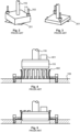
- Fig. 2 and 3 illustrate a precooling principle known from patent publication EP 2409096 B1 .
- the holes 201 in the flanges and the sample holder 115 are not round but are shaped in such a way that in one rotational position, the outermost parts of the sample holder 115 abut the flange adjacent to the hole 201. These parts are provided with screw holes 301.
- the sample changer comprises screwable rods 202, whereby the sample holder 115 may be temporarily fastened to the flange by means of threads located at an outermost end of the screwable rods (or by means of separate bolts to be rotated with the screwable rods) as in Fig. 2 .
- the threads or bolts are unscrewed and the sample changer is rotated to a suitable position in which it can move through the hole 201 in the flange as in Fig. 3 .
- the same threads or bolts may also be used for fixing the sample holder 115 in the target region.
- thermally conductive springs are also known in the prior art, which is illustrated in Fig. 4 and 5 .
- a sample 401 is fastened to a sample holder 115 that is in this case substantially disc-shaped and manufactured from a material having good thermal conductivity.
- a plurality of springs 402, the material of which is both elastic and thermally conductive, are fastened around a hole in the flange 105.
- JP 2001 304709 A relates to a dilution refrigerator for continuously obtaining an ultralow temperature using liquid helium.
- the objects of the invention are achieved by using in the structure a heat transfer section and a separate spring section, the elasticity of which forces the heat transfer section into good contact with the object being cooled.
- the heat transfer section comprises a plurality of heat transfer elements arranged in the form of a ring, whereby said contact surface is formed by those surfaces of the heat transfer elements which face towards the interior of the ring.
- said spring section comprises a support ring fastened on top of said fastening ring and having an inner surface, and a plurality of spring tabs supported to the inner surface of said support ring and arranged to exert on said heat transfer tabs said spring force.
- said heat transfer section is manufactured from copper or silver. This provides the advantage that the thermal conductivity of the heat transfer section is high.
- the heat transfer section manufactured from copper or silver is coated with gold. This provides the advantage that the relevant surfaces of the heat transfer section are not oxidized and that they maintain a good thermal conductivity for a long time.
- said spring section is manufactured from a beryllium-copper alloy. This provides the advantage that the elastic properties of the spring section are well-suited for use in an environment containing very low temperatures, as in a cryostat.
- the arrangement comprises a sample holder that forms at least a part of said object being moved within the cryostat.
- the sample holder may in this case comprise a first section that is in diameter compatible with said first diameter, and a second section that is in diameter compatible with said second diameter.
- Said second section may be arranged in that part of the sample holder which is located, in relation to the first section, towards the same direction as said second cooling structure in located in relation to said first cooling structure.
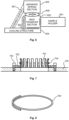
- Fig. 6 is a diagram of the principle of a device for providing a thermally conductive coupling when the purpose is to cool an object 601 being moved within a cryostat.
- the object 601 being moved is in Fig. 6 referred to as a sample holder, but it may also be some other object being moved.
- the actual purpose may be to move and cool some other item, for example a sample fastened to the sample holder.
- such item being moved indirectly (such as the sample) and the item being used for moving it (such as the sample holder) may generally be considered as one object 601 being moved within the cryostat.
- the device comprises a heat transfer section 602 forming a contact surface for the object 601.
- the purpose is thus that the object 601 being moved and the heat transfer section 602 are brought into physical contact with each other, whereby the heat may be transferred therebetween by conduction from one solid object to the other.
- the thermally conductive coupling based on a physical contact between the objects is illustrated by crosshatching in Fig. 6 .
- the heat transfer section 602 may consist of one or more pieces.
- the separation of the spring section 605 from the heat transfer section 602 means that - in contrast to the prior art - the thermal conduction between the object 601 and the cooling structure 604 and the force maintaining the thermally conductive contact are not attempted to be provided with the same structural element.
- the separation does not mean that the spring section 605 and the heat transfer section 602 should be located in complete separation from each other, in different parts of the structure. It means that the spring section 605 may be one piece (or a plurality of pieces) and the heat transfer section 602 may be another piece (or a plurality of other pieces).
- the piece or the pieces which form the spring section 605 may be manufactured from a different material than that other piece or those other pieces which form the heat transfer section.
- Fig. 11 illustrates a device according to one embodiment for providing a thermally conductive coupling in order to cool a device being moved within a cryostat.
- the embodiment of Fig. 11 is similar to those described above in that the device comprises a heat transfer section, means for fastening it to a cooling structure (for example, flange 105 in Fig. 11 ) and a spring section which is separate from the heat transfer section.
- the heat transfer section forms a contact surface for the object being moved within the cryostat in order to be cooled.
- the fastening to the cooling structure is such that this contact surface remains free.
- the spring section is arranged to exert on the heat transfer section a spring force pushing the contact surface in that direction in which it is intended to contact said object.
- the heat transfer section comprises a plurality of heat transfer elements 1101 arranged in the form of a ring, which in this embodiment may also be referred to as heat transfer tabs.
- the contact surface is formed by those surfaces of the heat transfer tabs 1101 which face towards the interior of the ring.
- the spring section comprises a plurality of spring elements 1102 disposed outside of the heat transfer tabs 1101 arranged in the form of a ring and pushing the heat transfer tabs 1101 towards the centre of the ring.
- the device also comprises means for supporting the spring section to the cooling structure. These means comprise rings 1103, 1104 and 1105 and bolts 1106, the structure and operation of which is explained in more detail below.
- the unit formed by the heat transfer tabs 1101 and the fastening ring 1104 is advantageously manufactured from a material conducting heat as well as possible at the relatively low temperatures relating to the normal operation of the cryostat.
- materials include, for example, copper and silver.
- the heat transfer tabs 1101 and the fastening ring 1104 may be coated with gold and/or provided with other such coating or surface treatment which improves their ability to form a thermally conductive coupling with those parts with which they are in contact.
- the contact surface formed by those surfaces of the heat transfer tabs 1101 which face towards the interior of the ring should advantageously be made rather hard, so it would not be scratched by the repeated sliding contacts with the object being cooled.
- the heat transfer tabs 1101 may be manufactured by cutting, from a material sheet of a suitable thickness, a comb-shaped part, the length of which corresponds to the circumference of the inner edge of the fastening ring 1104.
- the continuous edge of the comb-shaped part may be fastened around the inner edge of the fastening ring 1104 using a suitable metal joining method such as welding or soldering.
- the spring section of the device according to the embodiment of Fig. 11 comprises a support ring 1103 fastened on top of the fastening ring 1104.
- the spring elements of the spring section are a plurality of spring tabs 1102 supported to the inner surface of the support ring 1103 and arranged to exert on the heat transfer tabs 1101 the spring force pushing them towards the centre of the ring formed by the heat transfer tabs 1101.
- the upper fastening ring 1105 is not necessary, if the object being moved has sufficiently conical contours for opening the ring formed by the heat transfer tabs 1101 and/or the free end of each heat transfer tab 1101 can otherwise be kept bent to a sufficient degree away from the centre line of the ring.
- One object is thus to present an arrangement by which a thermally conductive coupling that is as good as possible for cooling an object being moved within a cryostat could be ensured in a target region, although it may also be precooled in other parts of the cryostat before it reaches the target region.
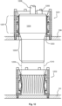
- Fig. 12 illustrates an example of an arrangement for cooling an object being moved within a cryostat.
- the arrangement comprises a first cooling structure (here: flange 108) and a first device 1201 fastened thereto, which is herein illustrated substantially as in Fig. 11 but which may be a device according to any of the embodiments described above.
- the arrangement comprises a second cooling structure (here: flange 111) and a second device 1202 fastened thereto. It is also illustrated herein substantially as in Fig. 11 , but also the second device 1202 may be in accordance with any of the embodiments described above.
- the first cooling structure i.e. flange 108, comprises an opening 1203 that is concentric with the first device 1201 and the second device 1202.
- the first device 1201 and the second device 1202 are not exactly the same size.
- a contact surface of the device forms a ring having a first diameter.
- a contact surface of the device forms a ring having a second diameter.
- the second diameter is smaller than the first diameter.
- the second cooling structure 111 forms a target region to which the object being cooled in the cryostat is intended to be fastened.
- the circular contact surface in that device which is located in the target region is smaller in diameter than in that or those devices which is or are used for precooling the object before it reaches the target region.
- the object being moved within the cryostat is illustrated in Fig. 12 , which object is in this case a sample holder 1204.
- the sample holder 1204 forms only a part of the object being moved within the cryostat, because in this example there is a sample 1205 fastened to the sample holder 1204 and a probe 1206 moving with the sample holder.
- the sample holder 1204 comprises a first portion 1207 that is in diameter compatible with said first diameter, i.e. the diameter of the contact surface of the first device 1201.
- the sample holder 1204 comprises a second portion 1208 that is in diameter compatible with said second diameter, i.e. the diameter of the contact surface of the second device 1202.
- the compatibility between the diameter of the portion in the sample holder 1204 and the corresponding diameter of the contact surface of the device used for the cooling is illustrated by a comparison in which the first device 1201 is compared with the second device 1202 in a situation shown in Fig. 12 .
- the sample holder 1204 is situated at a point where the first device 1201 is used for cooling it.
- the larger-diameter portion 1207 of the sample holder 1204 is pressed against the contact surface of the first device 1201. According to the principle described above, this means that the heat transfer tabs in the first device 1201 are pushed outwards from the so-called rest position in which they would lie if the sample holder 1204 was not situated at them.
- the opening 1203 in the cooling structure 108 is in diameter larger than the diameter of either of the portions 1207 or 1208 of the sample holder 1204. This condition is provided because the sample holder 1204 is not intended to touch the edges of the opening 1203 at any stage but just move smoothly through it.
Landscapes
- Engineering & Computer Science (AREA)
- Physics & Mathematics (AREA)
- Mechanical Engineering (AREA)
- Thermal Sciences (AREA)
- General Engineering & Computer Science (AREA)
- Chemical & Material Sciences (AREA)
- Combustion & Propulsion (AREA)
- Cooling Or The Like Of Electrical Apparatus (AREA)
Claims (12)
- Kryostat, umfassend eine Kühlstruktur (105, 107, 108, 111) und eine daran befestigte Vorrichtung zum Bereitstellen einer thermisch leitfähigen Kopplung zum Kühlen eines Objekts (601), das innerhalb des Kryostats bewegt wird, die Vorrichtung umfassend:- einen Wärmeübertragungsabschnitt (602), der eine Kontaktfläche für das Objekt (601) bildet, und- Mittel zum Befestigen des Wärmeübertragungsabschnitts (602) an einer Kühlstruktur (105, 107, 111, 604) in einer solchen Weise, dass die Kontaktfläche frei bleibt,dadurch gekennzeichnet, dass:- die Vorrichtung einen Federabschnitt (605) umfasst, der von dem Wärmeübertragungsabschnitt (602) getrennt ist und der so angeordnet ist, dass er auf den Wärmeübertragungsabschnitt (602) eine Federkraft (606) ausübt, welche die Kontaktfläche in die Richtung drückt, in der sie das Objekt (601) berühren soll,- der Wärmeübertragungsabschnitt (602) eine Vielzahl von Wärmeübertragungselementen (701, 901, 1101) umfasst, die in Form eines Rings angeordnet sind, wobei die Kontaktfläche durch die Flächen der Wärmeübertragungselemente (701, 901, 1101) gebildet wird, die dem Inneren des Rings zugewandt sind, und- der Federabschnitt (605) ein oder mehrere Federelemente (704, 903, 1102) umfasst, die außerhalb der Wärmeübertragungselemente (701, 901, 1101) platziert sind, die in Form eines Rings angeordnet sind und die Wärmeübertragungselemente (701, 901, 1101) in Richtung der Mitte des Rings drücken.
- Kryostat nach einem der vorhergehenden Ansprüche, dadurch gekennzeichnet, dass er Mittel (607, 904, 905, 1001, 1103, 1106) zum Stützen des Federabschnitts (605) an der Kühlstruktur (105, 107, 111, 604) umfasst.
- Kryostat nach einem der vorhergehenden Ansprüche, dadurch gekennzeichnet, dass der Wärmeübertragungsabschnitt (602) umfasst:- einen Befestigungsring (1104), der eine Innenkante aufweist, und- eine Vielzahl von Wärmeübertragungslaschen (1101), die an einem Ende an der Innenkante des Befestigungsrings (1104) befestigt sind und von denen ein anderes, freies Ende in einer im Wesentlichen senkrechten Richtung zu einer Ebene gerichtet ist, die durch den Befestigungsring (1104) definiert ist.
- Kryostat nach Anspruch 3, dadurch gekennzeichnet, dass der Federabschnit (605) umfasst:- einen Stützring (1103), der oben auf dem Befestigungsring (1104) befestigt ist und eine Innenfläche aufweist und- eine Vielzahl von Federlaschen (1102), die an der Innenfläche des Stützrings (1103) gestützt und so angeordnet sind, dass sie auf die Wärmeübertragungslaschen (1101) die Federkraft (606) ausüben.
- Kryostat nach Anspruch 4, dadurch gekennzeichnet, dass die Federlaschen (1102) ein durchgehendes Band von Federlaschen bilden, das sich um die Innenfläche des Stützrings (1103) herum erstreckt, wobei das Band von Federlaschen an einer oder mehreren Nuten an der Innenfläche des Stützrings (1103) gestützt ist.
- Kryostat nach Anspruch 4 oder 5, dadurch gekennzeichnet, dass er ferner einen oberen Befestigungsring (1105) umfasst, der oben auf dem Stützring (1103) befestigt und so angeordnet ist, dass er das freie Ende von jeder der Wärmeübertragungslaschen (1101) in einer Position stützt, die sich weiter von der Mittellinie des Rings befindet, der von den Wärmeübertragungslaschen (1101) gebildet wird, als die Mitte der Wärmeübertragungslaschen (1101).
- Kryostat nach einem der vorhergehenden Ansprüche, dadurch gekennzeichnet, dass der Wärmeübertragungsabschnitt (602) aus Kupfer oder Silber hergestellt ist.
- Kryostat nach Anspruch 7, dadurch gekennzeichnet, dass der Wärmeübertragungsabschnitt (602), der aus Kupfer oder Silber hergestellt ist, mit Gold beschichtet ist.
- Kryostat nach einem der vorhergehenden Ansprüche, dadurch gekennzeichnet, dass der Federabschnitt (605) aus einer Beryllium-KupferLegierung hergestellt ist.
- Kryostat nach Anspruch 1, dadurch gekennzeichnet, dass:- der Kryostat eine Anordnung zum Kühlen eines Objekts umfasst, das innerhalb des Kryostats bewegt wird, wobei die Anordnung eine erste Kühlstruktur (108) und eine daran befestigte erste Vorrichtung (1201) umfasst, bei der es sich um eine Vorrichtung nach einem der Ansprüche 1-9 handelt,- die Anordnung eine zweite Kühlstruktur (111) und eine zweite daran befestigte Vorrichtung (1202) umfasst, bei der es sich um eine Vorrichtung nach einem der Ansprüche 1-9 handelt,- die erste Kühlstruktur (108) eine Öffnung (1203) umfasst, die mit der ersten und zweiten Vorrichtung (1201, 1202) konzentrisch ist,- in der ersten Vorrichtung (1201) eine Kontaktfläche der Vorrichtung einen Ring bildet, der einen ersten Durchmesser aufweist,- in der zweiten Vorrichtung (1202) eine Kontaktfläche der Vorrichtung einen Ring bildet, der einen zweiten Durchmesser aufweist, der kleiner als der erste Durchmesser ist, und- ein Durchmesser der Öffnung (1203) größer als der erste und zweite Durchmesser ist.
- Kryostat nach Anspruch 10, dadurch gekennzeichnet, dass die zweite Kühlstruktur (111) einen Zielbereich zum Befestigen des Objekts bildet, das in dem Kryostat gekühlt wird.
- Kryostat nach einem der Ansprüche 10-11, dadurch gekennzeichnet, dass:- die Anordnung einen Probenhalter (1204) umfasst, der mindestens einen Teil des Objekts bildet, das innerhalb des Kryostats bewegt wird,- der Probenhalter einen ersten Abschnitt (1207) umfasst, der im Durchmesser mit dem ersten Durchmesser kompatibel ist,- der Probenhalter einen zweiten Abschnitt (1208) umfasst, der im Durchmesser mit dem zweiten Durchmesser kompatibel ist, und- der zweite Abschnitt (1208) in dem Teil des Probenhalters (1204) angeordnet ist, der sich in Bezug auf den ersten Abschnitt (1207) in derselben Richtung befindet, in der sich die zweite Kühlstruktur (111) in Bezug auf die erste Kühlstruktur (108) befindet.
Priority Applications (1)
| Application Number | Priority Date | Filing Date | Title |
|---|---|---|---|
| EP24179848.7A EP4403849A3 (de) | 2020-05-13 | 2021-05-11 | Kryostat |
Applications Claiming Priority (2)
| Application Number | Priority Date | Filing Date | Title |
|---|---|---|---|
| FI20205481A FI129268B (fi) | 2020-05-13 | 2020-05-13 | Laite ja menetelmä lämpöä johtavan kytkennän tekemiseksi |
| PCT/FI2021/050347 WO2021229149A1 (en) | 2020-05-13 | 2021-05-11 | Device and method for providing a thermally conductive coupling |
Related Child Applications (2)
| Application Number | Title | Priority Date | Filing Date |
|---|---|---|---|
| EP24179848.7A Division-Into EP4403849A3 (de) | 2020-05-13 | 2021-05-11 | Kryostat |
| EP24179848.7A Division EP4403849A3 (de) | 2020-05-13 | 2021-05-11 | Kryostat |
Publications (3)
| Publication Number | Publication Date |
|---|---|
| EP4150272A1 EP4150272A1 (de) | 2023-03-22 |
| EP4150272B1 true EP4150272B1 (de) | 2024-07-10 |
| EP4150272C0 EP4150272C0 (de) | 2024-07-10 |
Family
ID=76034645
Family Applications (2)
| Application Number | Title | Priority Date | Filing Date |
|---|---|---|---|
| EP24179848.7A Pending EP4403849A3 (de) | 2020-05-13 | 2021-05-11 | Kryostat |
| EP21726952.1A Active EP4150272B1 (de) | 2020-05-13 | 2021-05-11 | Kryostat |
Family Applications Before (1)
| Application Number | Title | Priority Date | Filing Date |
|---|---|---|---|
| EP24179848.7A Pending EP4403849A3 (de) | 2020-05-13 | 2021-05-11 | Kryostat |
Country Status (8)
| Country | Link |
|---|---|
| US (2) | US12013170B2 (de) |
| EP (2) | EP4403849A3 (de) |
| JP (1) | JP7755604B2 (de) |
| KR (1) | KR20230034212A (de) |
| CN (1) | CN116134263A (de) |
| CA (1) | CA3183158A1 (de) |
| FI (1) | FI129268B (de) |
| WO (1) | WO2021229149A1 (de) |
Families Citing this family (3)
| Publication number | Priority date | Publication date | Assignee | Title |
|---|---|---|---|---|
| FI129268B (fi) | 2020-05-13 | 2021-10-29 | Bluefors Oy | Laite ja menetelmä lämpöä johtavan kytkennän tekemiseksi |
| FI131647B1 (en) * | 2024-06-28 | 2025-08-21 | Bluefors Oy | CRYOGENIC COOLING SYSTEM |
| FI131722B1 (en) * | 2024-09-24 | 2025-10-16 | Bluefors Oy | Devices and methods for making a thermally conductive connection in a cryostat |
Citations (2)
| Publication number | Priority date | Publication date | Assignee | Title |
|---|---|---|---|---|
| JP2001304709A (ja) * | 2000-04-20 | 2001-10-31 | Taiyo Toyo Sanso Co Ltd | 希釈冷凍機 |
| EP2409096B1 (de) * | 2009-03-16 | 2019-08-21 | Oxford Instruments Nanotechnology Tools Limited | Kryogenfreie kühlvorrichtung und verfahren |
Family Cites Families (16)
| Publication number | Priority date | Publication date | Assignee | Title |
|---|---|---|---|---|
| US3306075A (en) * | 1965-10-04 | 1967-02-28 | Hughes Aircraft Co | Thermal coupling structure for cryogenic refrigeration |
| US3327779A (en) * | 1965-12-16 | 1967-06-27 | Jacoby John Hull | Heat dissipating device and method |
| US4344302A (en) * | 1981-06-08 | 1982-08-17 | Hughes Aircraft Company | Thermal coupling structure for cryogenic refrigeration |
| US4707726A (en) * | 1985-04-29 | 1987-11-17 | United Technologies Automotive, Inc. | Heat sink mounting arrangement for a semiconductor |
| JPH0641098Y2 (ja) * | 1988-05-12 | 1994-10-26 | 富士電機株式会社 | 冷凍機の膨張シリンダ冷却側端面への伝熱端子取付け構造 |
| DE9014091U1 (de) | 1990-10-10 | 1992-02-13 | Robert Bosch Gmbh, 7000 Stuttgart | Federelement für eine Baugruppe eines elektronischen Steuergerätes |
| JPH09287837A (ja) | 1996-04-19 | 1997-11-04 | Kobe Steel Ltd | 極低温冷却装置 |
| US5730210A (en) * | 1997-02-24 | 1998-03-24 | Silicon Integrated Systems Corporation | Heat sink having an assembling device |
| JP3497440B2 (ja) | 2000-03-31 | 2004-02-16 | 大陽東洋酸素株式会社 | 低温機械的熱スイッチ |
| US6400565B1 (en) | 2000-04-21 | 2002-06-04 | Dell Products L.P. | Thermally conductive interface member |
| TWM317606U (en) * | 2007-01-31 | 2007-08-21 | Cooler Master Co Ltd | Easy-to-assemble-and-dismantle heat dissipation device |
| NL2001755C2 (nl) * | 2008-07-03 | 2010-01-05 | Giorgio Frossati | Houder voor een tot een lage temperatuur in een vacuümruimte af te koelen preparaat en 3he-4he mengkoelmachine ingericht voor het opnemen van een dergelijke houder. |
| GB2513151B (en) * | 2013-04-17 | 2015-05-20 | Siemens Plc | Improved thermal contact between cryogenic refrigerators and cooled components |
| GB2538084B (en) | 2015-05-06 | 2017-07-19 | Siemens Healthcare Ltd | Actuation arrangement |
| CN210074730U (zh) | 2019-08-28 | 2020-02-14 | 遂宁市运长机械设备制造有限公司 | 用于海底石油管道的电缆的夹持装置 |
| FI129268B (fi) | 2020-05-13 | 2021-10-29 | Bluefors Oy | Laite ja menetelmä lämpöä johtavan kytkennän tekemiseksi |
-
2020
- 2020-05-13 FI FI20205481A patent/FI129268B/fi active IP Right Review Request
-
2021
- 2021-05-11 KR KR1020227043514A patent/KR20230034212A/ko active Pending
- 2021-05-11 WO PCT/FI2021/050347 patent/WO2021229149A1/en not_active Ceased
- 2021-05-11 EP EP24179848.7A patent/EP4403849A3/de active Pending
- 2021-05-11 JP JP2022569271A patent/JP7755604B2/ja active Active
- 2021-05-11 EP EP21726952.1A patent/EP4150272B1/de active Active
- 2021-05-11 CN CN202180061300.9A patent/CN116134263A/zh active Pending
- 2021-05-11 CA CA3183158A patent/CA3183158A1/en active Pending
- 2021-05-11 US US17/998,627 patent/US12013170B2/en active Active
-
2024
- 2024-05-08 US US18/658,619 patent/US20240288214A1/en active Pending
Patent Citations (2)
| Publication number | Priority date | Publication date | Assignee | Title |
|---|---|---|---|---|
| JP2001304709A (ja) * | 2000-04-20 | 2001-10-31 | Taiyo Toyo Sanso Co Ltd | 希釈冷凍機 |
| EP2409096B1 (de) * | 2009-03-16 | 2019-08-21 | Oxford Instruments Nanotechnology Tools Limited | Kryogenfreie kühlvorrichtung und verfahren |
Non-Patent Citations (1)
| Title |
|---|
| LE JIA LEO: "The Quest for Absolute Zero Temperature - Installation of BlueFors Dilution Fridge | Physics | Brown University", 10 October 2019 (2019-10-10), pages 1 - 4, XP093082827, Retrieved from the Internet <URL:https://www.brown.edu/academics/physics/news/2019/10/quest-absolute-zero-temperature-installation-bluefors-dilution-fridge> [retrieved on 20230918] * |
Also Published As
| Publication number | Publication date |
|---|---|
| US20240288214A1 (en) | 2024-08-29 |
| CA3183158A1 (en) | 2021-11-18 |
| US12013170B2 (en) | 2024-06-18 |
| EP4403849A2 (de) | 2024-07-24 |
| FI129268B (fi) | 2021-10-29 |
| FI20205481A1 (fi) | 2021-10-29 |
| JP2023525169A (ja) | 2023-06-14 |
| EP4150272C0 (de) | 2024-07-10 |
| EP4150272A1 (de) | 2023-03-22 |
| KR20230034212A (ko) | 2023-03-09 |
| JP7755604B2 (ja) | 2025-10-16 |
| EP4403849A3 (de) | 2024-10-30 |
| WO2021229149A1 (en) | 2021-11-18 |
| US20230175756A1 (en) | 2023-06-08 |
| CN116134263A (zh) | 2023-05-16 |
Similar Documents
| Publication | Publication Date | Title |
|---|---|---|
| US20240288214A1 (en) | Device and method for providing a thermally conductive coupling | |
| EP4027081B1 (de) | Vorrichtung und verfahren zur kryogenfreien kühlung | |
| Harrell et al. | Performance tests of a two phase ejector | |
| EP1877809B1 (de) | Baugruppe zum regeln der temperatur einer integrierten schaltung | |
| Li et al. | Machine learning studies for magnetic compositionally complex alloys: A critical review | |
| JP2023516097A (ja) | 順応センタリングフィンガを有するリング構造 | |
| CN103216526B (zh) | 一种对称螺旋交叉簧片柔性轴承 | |
| US5129448A (en) | Low torque hinged heat transfer joint | |
| JP7131868B2 (ja) | 熱スイッチ | |
| US12104996B2 (en) | Flat plate sample holder expansion structure used in vacuum | |
| CN220474541U (zh) | 一种热开关及超导磁体 | |
| JP7450406B2 (ja) | 極低温装置および熱スイッチ | |
| CN1961178B (zh) | 低温恒温器的制冷机接口 | |
| US11971141B2 (en) | Low thermal conductivity support system for cryogenic environments | |
| JP2024067844A (ja) | 基板処理装置 | |
| US3476936A (en) | Apparatus for positioning specimens in electron microscopes or electron diffraction cameras | |
| JP7496229B2 (ja) | 極低温冷凍機の装着構造および極低温冷凍機 | |
| US20210116404A1 (en) | Multi-screen supporting device in high-temperature adiabatic calorimeter | |
| CN220540730U (zh) | 一种热工仪表用角度调节支架 | |
| WO2007101305A1 (en) | Low temperature heatsinking system | |
| EP4243059B1 (de) | Anordnung zum drehbaren positionieren eines substrats | |
| JP3248759U (ja) | 冷却システム及び超伝導型磁気共鳴イメージング装置 | |
| CN116006578B (zh) | 自对中导向机构 | |
| SU890192A1 (ru) | Устройство дл измерени теплопроводности твердых образцов в области низких температур | |
| CN111473192B (zh) | 一种超高真空兼容的热辐射屏蔽装置及其屏蔽方法 |
Legal Events
| Date | Code | Title | Description |
|---|---|---|---|
| STAA | Information on the status of an ep patent application or granted ep patent |
Free format text: STATUS: UNKNOWN |
|
| STAA | Information on the status of an ep patent application or granted ep patent |
Free format text: STATUS: THE INTERNATIONAL PUBLICATION HAS BEEN MADE |
|
| TPAC | Observations filed by third parties |
Free format text: ORIGINAL CODE: EPIDOSNTIPA |
|
| PUAI | Public reference made under article 153(3) epc to a published international application that has entered the european phase |
Free format text: ORIGINAL CODE: 0009012 |
|
| STAA | Information on the status of an ep patent application or granted ep patent |
Free format text: STATUS: REQUEST FOR EXAMINATION WAS MADE |
|
| 17P | Request for examination filed |
Effective date: 20221205 |
|
| AK | Designated contracting states |
Kind code of ref document: A1 Designated state(s): AL AT BE BG CH CY CZ DE DK EE ES FI FR GB GR HR HU IE IS IT LI LT LU LV MC MK MT NL NO PL PT RO RS SE SI SK SM TR |
|
| TPAC | Observations filed by third parties |
Free format text: ORIGINAL CODE: EPIDOSNTIPA |
|
| DAV | Request for validation of the european patent (deleted) | ||
| DAX | Request for extension of the european patent (deleted) | ||
| TPAC | Observations filed by third parties |
Free format text: ORIGINAL CODE: EPIDOSNTIPA |
|
| STAA | Information on the status of an ep patent application or granted ep patent |
Free format text: STATUS: EXAMINATION IS IN PROGRESS |
|
| 17Q | First examination report despatched |
Effective date: 20230921 |
|
| GRAP | Despatch of communication of intention to grant a patent |
Free format text: ORIGINAL CODE: EPIDOSNIGR1 |
|
| STAA | Information on the status of an ep patent application or granted ep patent |
Free format text: STATUS: GRANT OF PATENT IS INTENDED |
|
| TPAC | Observations filed by third parties |
Free format text: ORIGINAL CODE: EPIDOSNTIPA |
|
| INTG | Intention to grant announced |
Effective date: 20240214 |
|
| GRAS | Grant fee paid |
Free format text: ORIGINAL CODE: EPIDOSNIGR3 |
|
| GRAA | (expected) grant |
Free format text: ORIGINAL CODE: 0009210 |
|
| STAA | Information on the status of an ep patent application or granted ep patent |
Free format text: STATUS: THE PATENT HAS BEEN GRANTED |
|
| AK | Designated contracting states |
Kind code of ref document: B1 Designated state(s): AL AT BE BG CH CY CZ DE DK EE ES FI FR GB GR HR HU IE IS IT LI LT LU LV MC MK MT NL NO PL PT RO RS SE SI SK SM TR |
|
| REG | Reference to a national code |
Ref country code: CH Ref legal event code: EP |
|
| REG | Reference to a national code |
Ref country code: DE Ref legal event code: R096 Ref document number: 602021015509 Country of ref document: DE |
|
| U01 | Request for unitary effect filed |
Effective date: 20240718 |
|
| U07 | Unitary effect registered |
Designated state(s): AT BE BG DE DK EE FI FR IT LT LU LV MT NL PT RO SE SI Effective date: 20240902 |
|
| PG25 | Lapsed in a contracting state [announced via postgrant information from national office to epo] |
Ref country code: NO Free format text: LAPSE BECAUSE OF FAILURE TO SUBMIT A TRANSLATION OF THE DESCRIPTION OR TO PAY THE FEE WITHIN THE PRESCRIBED TIME-LIMIT Effective date: 20241010 |
|
| PG25 | Lapsed in a contracting state [announced via postgrant information from national office to epo] |
Ref country code: GR Free format text: LAPSE BECAUSE OF FAILURE TO SUBMIT A TRANSLATION OF THE DESCRIPTION OR TO PAY THE FEE WITHIN THE PRESCRIBED TIME-LIMIT Effective date: 20241011 Ref country code: PL Free format text: LAPSE BECAUSE OF FAILURE TO SUBMIT A TRANSLATION OF THE DESCRIPTION OR TO PAY THE FEE WITHIN THE PRESCRIBED TIME-LIMIT Effective date: 20240710 |
|
| PG25 | Lapsed in a contracting state [announced via postgrant information from national office to epo] |
Ref country code: IS Free format text: LAPSE BECAUSE OF FAILURE TO SUBMIT A TRANSLATION OF THE DESCRIPTION OR TO PAY THE FEE WITHIN THE PRESCRIBED TIME-LIMIT Effective date: 20241110 |
|
| PG25 | Lapsed in a contracting state [announced via postgrant information from national office to epo] |
Ref country code: HR Free format text: LAPSE BECAUSE OF FAILURE TO SUBMIT A TRANSLATION OF THE DESCRIPTION OR TO PAY THE FEE WITHIN THE PRESCRIBED TIME-LIMIT Effective date: 20240710 |
|
| PG25 | Lapsed in a contracting state [announced via postgrant information from national office to epo] |
Ref country code: RS Free format text: LAPSE BECAUSE OF FAILURE TO SUBMIT A TRANSLATION OF THE DESCRIPTION OR TO PAY THE FEE WITHIN THE PRESCRIBED TIME-LIMIT Effective date: 20241010 Ref country code: ES Free format text: LAPSE BECAUSE OF FAILURE TO SUBMIT A TRANSLATION OF THE DESCRIPTION OR TO PAY THE FEE WITHIN THE PRESCRIBED TIME-LIMIT Effective date: 20240710 |
|
| PG25 | Lapsed in a contracting state [announced via postgrant information from national office to epo] |
Ref country code: RS Free format text: LAPSE BECAUSE OF FAILURE TO SUBMIT A TRANSLATION OF THE DESCRIPTION OR TO PAY THE FEE WITHIN THE PRESCRIBED TIME-LIMIT Effective date: 20241010 Ref country code: PL Free format text: LAPSE BECAUSE OF FAILURE TO SUBMIT A TRANSLATION OF THE DESCRIPTION OR TO PAY THE FEE WITHIN THE PRESCRIBED TIME-LIMIT Effective date: 20240710 Ref country code: NO Free format text: LAPSE BECAUSE OF FAILURE TO SUBMIT A TRANSLATION OF THE DESCRIPTION OR TO PAY THE FEE WITHIN THE PRESCRIBED TIME-LIMIT Effective date: 20241010 Ref country code: IS Free format text: LAPSE BECAUSE OF FAILURE TO SUBMIT A TRANSLATION OF THE DESCRIPTION OR TO PAY THE FEE WITHIN THE PRESCRIBED TIME-LIMIT Effective date: 20241110 Ref country code: HR Free format text: LAPSE BECAUSE OF FAILURE TO SUBMIT A TRANSLATION OF THE DESCRIPTION OR TO PAY THE FEE WITHIN THE PRESCRIBED TIME-LIMIT Effective date: 20240710 Ref country code: GR Free format text: LAPSE BECAUSE OF FAILURE TO SUBMIT A TRANSLATION OF THE DESCRIPTION OR TO PAY THE FEE WITHIN THE PRESCRIBED TIME-LIMIT Effective date: 20241011 Ref country code: ES Free format text: LAPSE BECAUSE OF FAILURE TO SUBMIT A TRANSLATION OF THE DESCRIPTION OR TO PAY THE FEE WITHIN THE PRESCRIBED TIME-LIMIT Effective date: 20240710 |
|
| PG25 | Lapsed in a contracting state [announced via postgrant information from national office to epo] |
Ref country code: SM Free format text: LAPSE BECAUSE OF FAILURE TO SUBMIT A TRANSLATION OF THE DESCRIPTION OR TO PAY THE FEE WITHIN THE PRESCRIBED TIME-LIMIT Effective date: 20240710 |
|
| PG25 | Lapsed in a contracting state [announced via postgrant information from national office to epo] |
Ref country code: CZ Free format text: LAPSE BECAUSE OF FAILURE TO SUBMIT A TRANSLATION OF THE DESCRIPTION OR TO PAY THE FEE WITHIN THE PRESCRIBED TIME-LIMIT Effective date: 20240710 |
|
| PG25 | Lapsed in a contracting state [announced via postgrant information from national office to epo] |
Ref country code: SK Free format text: LAPSE BECAUSE OF FAILURE TO SUBMIT A TRANSLATION OF THE DESCRIPTION OR TO PAY THE FEE WITHIN THE PRESCRIBED TIME-LIMIT Effective date: 20240710 |
|
| PLBE | No opposition filed within time limit |
Free format text: ORIGINAL CODE: 0009261 |
|
| STAA | Information on the status of an ep patent application or granted ep patent |
Free format text: STATUS: NO OPPOSITION FILED WITHIN TIME LIMIT |
|
| 26N | No opposition filed |
Effective date: 20250411 |
|
| U20 | Renewal fee for the european patent with unitary effect paid |
Year of fee payment: 5 Effective date: 20250527 |
|
| PGFP | Annual fee paid to national office [announced via postgrant information from national office to epo] |
Ref country code: GB Payment date: 20250527 Year of fee payment: 5 |
|
| REG | Reference to a national code |
Ref country code: CH Ref legal event code: H13 Free format text: ST27 STATUS EVENT CODE: U-0-0-H10-H13 (AS PROVIDED BY THE NATIONAL OFFICE) Effective date: 20251223 |
|
| PG25 | Lapsed in a contracting state [announced via postgrant information from national office to epo] |
Ref country code: CH Free format text: LAPSE BECAUSE OF NON-PAYMENT OF DUE FEES Effective date: 20250531 |
|
| PG25 | Lapsed in a contracting state [announced via postgrant information from national office to epo] |
Ref country code: MC Free format text: LAPSE BECAUSE OF FAILURE TO SUBMIT A TRANSLATION OF THE DESCRIPTION OR TO PAY THE FEE WITHIN THE PRESCRIBED TIME-LIMIT Effective date: 20240710 |
|
| PG25 | Lapsed in a contracting state [announced via postgrant information from national office to epo] |
Ref country code: IE Free format text: LAPSE BECAUSE OF NON-PAYMENT OF DUE FEES Effective date: 20250511 |