EP2409096B1 - Kryogenfreie kühlvorrichtung und verfahren - Google Patents
Kryogenfreie kühlvorrichtung und verfahren Download PDFInfo
- Publication number
- EP2409096B1 EP2409096B1 EP10710389.7A EP10710389A EP2409096B1 EP 2409096 B1 EP2409096 B1 EP 2409096B1 EP 10710389 A EP10710389 A EP 10710389A EP 2409096 B1 EP2409096 B1 EP 2409096B1
- Authority
- EP
- European Patent Office
- Prior art keywords
- holding device
- radiation shield
- sample holding
- sample
- heat radiation
- Prior art date
- Legal status (The legal status is an assumption and is not a legal conclusion. Google has not performed a legal analysis and makes no representation as to the accuracy of the status listed.)
- Active
Links
Images



Classifications
-
- F—MECHANICAL ENGINEERING; LIGHTING; HEATING; WEAPONS; BLASTING
- F25—REFRIGERATION OR COOLING; COMBINED HEATING AND REFRIGERATION SYSTEMS; HEAT PUMP SYSTEMS; MANUFACTURE OR STORAGE OF ICE; LIQUEFACTION SOLIDIFICATION OF GASES
- F25D—REFRIGERATORS; COLD ROOMS; ICE-BOXES; COOLING OR FREEZING APPARATUS NOT OTHERWISE PROVIDED FOR
- F25D19/00—Arrangement or mounting of refrigeration units with respect to devices or objects to be refrigerated, e.g. infrared detectors
-
- F—MECHANICAL ENGINEERING; LIGHTING; HEATING; WEAPONS; BLASTING
- F25—REFRIGERATION OR COOLING; COMBINED HEATING AND REFRIGERATION SYSTEMS; HEAT PUMP SYSTEMS; MANUFACTURE OR STORAGE OF ICE; LIQUEFACTION SOLIDIFICATION OF GASES
- F25B—REFRIGERATION MACHINES, PLANTS OR SYSTEMS; COMBINED HEATING AND REFRIGERATION SYSTEMS; HEAT PUMP SYSTEMS
- F25B9/00—Compression machines, plants or systems, in which the refrigerant is air or other gas of low boiling point
- F25B9/14—Compression machines, plants or systems, in which the refrigerant is air or other gas of low boiling point characterised by the cycle used, e.g. Stirling cycle
-
- F—MECHANICAL ENGINEERING; LIGHTING; HEATING; WEAPONS; BLASTING
- F25—REFRIGERATION OR COOLING; COMBINED HEATING AND REFRIGERATION SYSTEMS; HEAT PUMP SYSTEMS; MANUFACTURE OR STORAGE OF ICE; LIQUEFACTION SOLIDIFICATION OF GASES
- F25B—REFRIGERATION MACHINES, PLANTS OR SYSTEMS; COMBINED HEATING AND REFRIGERATION SYSTEMS; HEAT PUMP SYSTEMS
- F25B9/00—Compression machines, plants or systems, in which the refrigerant is air or other gas of low boiling point
- F25B9/14—Compression machines, plants or systems, in which the refrigerant is air or other gas of low boiling point characterised by the cycle used, e.g. Stirling cycle
- F25B9/145—Compression machines, plants or systems, in which the refrigerant is air or other gas of low boiling point characterised by the cycle used, e.g. Stirling cycle pulse-tube cycle
Definitions
- the invention relates to a cryogen free cooling apparatus and a method for using such an apparatus.
- a key challenge with these systems is that the sample is entered into the equipment at room temperature, typically around 300K and then moved to another position where thermal contact is made with a body at a much lower temperature which in some systems can be lower than 1K.
- the sample and associated mounting and connection equipment is usually pre-cooled either by passing it through cold cryogen gas on its way in to the system or by passing cold cryogen gas or liquid through the sample transfer mechanism, this reduces the thermal shock both on the sample and on the equipment.
- cryogenic systems that do not require the addition of liquid cryogens or that only require liquid nitrogen during initial cool down have been developed. These are generally known as cryogen free (or "cryofree") systems. These systems use a mechanical cooler such as a GM cooler, Stirling cooler or a pulse tube to provide the cooling power. Because the cooling power of commercially available coolers is somewhat lower than the cooling power available from a reservoir of liquid cryogen, these systems can typically take longer to warm up, change the sample and cool down. There is therefore a considerable need for a method of changing samples in cryogen free systems without the need to warm up the entire system.
- cryogen free systems there are a number of technical challenges when attempting to load a warm sample in to a cold cryostat. Firstly, the internals of the system are usually contained within a sealed vacuum vessel to reduce heat load. Secondly, within that sealed vacuum vessel, the sample space is usually enclosed by one or more radiation shields to further reduce the heat load. Thirdly, there are no liquid cryogens available to pre-cool the sample as it moves from room temperature to the cold mounting body. Also, electrical contacts need to be remotely made to the sample when it is loaded in the cryostat. This invention seeks to provide solutions to these problems.
- JP 2008-14878 A discloses a cryogen free cooling apparatus according to the preamble of claim 1.
- the sample loading apparatus further includes a vacuum vessel in which the sample holding device and elongate probe are movably mounted, the vacuum vessel being connectable to the aperture of the vacuum chamber wall.
- cryostat Although various cold bodies within the cryostat could be used, such as any cold surface coupled to the cooling stage of the cooling system or to an intermediate stage of a sub 4K cooler such as a still of a dilution refrigerator, it is most convenient to utilize the heat radiation shield already present.
- more than one heat radiation shield could be provided within the vacuum chamber. One or more of these could therefore be used further to pre-cool the sample.
- the apparatus further comprises a second heat radiation shield located inside the first radiation shield and surrounding the working region, the cryogen free cooling system having a second cooling stage, colder than the first cooling stage, coupled to the second heat radiation shield, the second radiation shield having an aperture aligned with the apertures of the first heat radiation shield and vacuum chamber wall so as to allow the sample holding device to pass therethrough, whereby the sample holding device can be releasably coupled for heat conduction to the second heat radiation shield.
- precooling of the sample it is not necessary for precooling of the sample to be carried out by connecting to each shield.
- precooling could be carried out solely on the innermost (typically 4K) shield. If three or more shields are provided, one or more could be used for precooling.
- the first heat radiation shield will be held at a temperature of between 45K and 90K while the second radiation shield (if provided) will be held at a temperature of less than 6K or even less than 4.2K.
- the heat radiation shield apertures may be left open but in order to reduce heat transfer, preferably each aperture is closable by a respective closure system.
- An example of a suitable closure system comprises one or more flexible flaps, or hinged and sprung flaps.
- the sample loading apparatus comprises two elongate probes, each coupled to the sample holding device, but in other embodiments a single elongate probe could be used. In both cases, preferably the or each probe is rotatable about its axis relative to the sample holding device. Of course, more than two probes could be used.
- the connector is conveniently formed by providing a screw thread at one end of the or each rod, the first connector cooperating with a screw thread on the first or second heat radiation shield to achieve thermal connection therebetween.
- the thermal connection can be achieved using a spring connection where the sample holding device is fitted with a or a plurality of thermally conductive springs which engage on an inner surface of the aperture of the radiation shield. That inner surface may be extended, for example by addition of a tube assembly or a thicker plate assembly to allow for engagement.
- the spring connectors could also be fixed on the heat or radiation shield and the sample holding device pushed on to them.
- the thermal connection could be via springs at the higher temperature shields and via screw contact at the lower temperature shields or any combination thereof.
- the connector could be defined by cone or wedge-shaped mating parts to amplify the contact pressure from the mounting mechanism. This significantly improves performance.
- the or each probe is releasably coupled to the sample holding device whereby a first operation of the probe(s) causes the sample holding device to be connected to a cold mounting body at the working region. A second operation enables the probe(s) to be released from the sample holding device and retracted. This enables the probe(s) to be removed from the vacuum chamber of the cryostat so as to reduce heat flow into the cryostat. Actuators to allow this could be provided on the probe or cold body.
- the cryogen free cooling apparatus can be used for a variety of purposes such as, scientific cryogenic research, quantum computing, experimental analysis, material characterisation, device characterisation, detector cooling, device cooling, DNP, NMR or any other application where cooling of matter to cryogenic temperatures is required and in many cases a magnet may be located within the cryostat surrounding the working region.
- FIG. 1 A first embodiment of the current invention is shown in more detail in Figures 1 to 5 .
- a sample 1 is mounted on a sample carrier or sample loading device 2 supported on thermally conductive rods of two rod or probe assemblies 3.
- the sample carrier 2 has space for a number of electrical and/or optical connectors (not shown) to allow connection to connectors on the primary cold body in the cryostat. This allows multiple push fit connectors to be used which gives high flexibility and optionally for the wiring to go through the cryostat rather than down the probe tube, which has significant thermal benefits.
- the ends of the two rod assemblies 3 are free to rotate within the carrier.
- a tube and flange assembly forms a vacuum vessel 6 surrounding the rod assemblies 3 and which is open at one end, this end being sealed against the bottom of a gate valve 5 when assembled to a cryostat 50.
- the rod assemblies pass through a pair of o-ring seals 7.
- the cryostat 50 comprises an outer vacuum vessel 4 which is closed except for a port 52 covered by a large diameter gate valve 5. Within the vacuum chamber 4 is located a first radiation shield 54 having an aperture 56 aligned with the aperture 52 of the vacuum chamber, and within the first radiation shield 54 is located a second radiation shield 10 having an aperture 58 aligned with the apertures 52,56.
- the radiation shields 10,54 surround a working region 20 at which is located a cold mounting body 15.
- the shields 10,54 are cooled by a conventional mechanical cooler such as a GM cooler, Stirling cooler, or pulse tube device. This is not shown in the drawings for reasons of clarity.
- a first stage of the mechanical cooler is thermally coupled to the shield 54 and a second, colder stage to the shield 10.
- the first shield 54 is cooled to a temperature of about 77K and the second shield 10 to a temperature of 6K or less, for example about 4.2K.
- the second shield is held at a temperature higher than 6K.
- each of the shields as well as the cold mounting body 15 held at the lowest temperature can be considered as "cold bodies".
- the aperture 56 of the shield 54 is defined by a plate 12 with a cut-out 17.
- the aperture 58 of the shield 10 is defined by another plate 12 and cut-out 17.
- the apertures 56,58 can be closed by a suitable closure mechanism.
- Figure 5 shows a close up cross-sectional view of one possible embodiment of such a mechanism.
- a or a plurality of flaps 25 are connected to the radiation shield 10 via a sprung hinge arrangement 26. When the rod assembly 3 passes through the flap assembly, the flap or plurality thereof 25 open.
- the flap or plurality thereof 25 may optionally be shaped or fitted with guide mechanisms to prevent the sample carrier, baffles or rod assemblies from catching on the flaps as the rod assembly and/or carrier is retracted.
- a sample 1 is loaded on to the sample carrier 2 and electrical or optical connections are made.
- the sample carrier 2 is then mounted on the end of the rod assemblies 3.
- the rod assemblies 3 are then retracted through the sliding o-ring seals 7 until the sample carrier is fully within the vacuum vessel 6.
- the vacuum vessel 6 is then attached to the gate valve 5 and air is pumped out of the vacuum vessel 6 through ports 8A,8B and valves 8.
- the gate valve is opened.
- the rod assemblies 3 are then pushed to move the sample carrier through the gate valve and to the first pre-cool position.
- Figure 2 shows the sample carrier 2 approaching the plate 12 of the shield 54 to thermally connect the sample carrier to a radiation shield pre-cool position defining a first cold body.
- the rod assemblies 3 have a key 22 ( Figure 4 ) on the end which, when engaged, turns a screw thread 18.
- the screw threads 18 are aligned with mating screw threads 19 on the plate 12 allowing the sample carrier 2 to be screwed to the plate 12 on the radiation shield 54, thereby making thermal contact.
- An optional thermometer (not shown) is provided on the sample carrier or rod assembly to allow the temperature of the sample carrier to be monitored during cool down. When the sample carrier 2 is sufficiently cold, the rod assemblies 3 are again rotated to separate the two screw threads.
- the entire rod and carrier assembly is then rotated by means of a rotating seal on the vacuum vessel 6 or gate valve 5, to allow the carrier 2 to pass through the cut-out 17.
- the carrier is then optionally connected in a similar manner to a or a plurality of optional additional radiation shields, such as the shield 10 (forming additional cold bodies).
- the rod assemblies 3 are pushed to their final position to allow connection of the sample carrier 2 to the cold body 15 which could by way of example be connected to the mixing chamber of a dilution refrigerator or a sample plate of a cryostat.
- Figure 3 shows the sample carrier 2 contacting the cold plate 15.
- the screw threads 18 are engaged in mating screw threads (not shown) on the cold plate 15.
- a number of optional push fit electrical and optional optical connections can be made between the sample carrier 2 and the cold body 15. These connectors are not shown on this diagram. In this view, two baffle assemblies 14 are also visible.
- baffle assemblies are free to slide on the rod assemblies 3 and are pushed or pulled towards the sample carrier by spring assemblies 21.
- baffle assemblies 14 are shown here in a retracted position, in reality they will be forced by the spring assemblies to contact the plates on the radiation shield, thereby closing the cut-outs 17 and making thermal contact.
- the baffle assemblies are also optionally connected to the rod assemblies using sliding thermal connections such as thermally conductive spring assemblies, thus allowing the heat passing down the rods from room temperature to be intercepted.
- Figure 4 shows a close up cross sectional view of the sample carrier and rod assemblies.
- the key 22 that inserts into a matching connection on the screw thread 18.
- On the key and rod assembly there is a screw thread 23 and on the sample carrier there is a matching screw thread 24.
- This arrangement means that if the rod assemblies are retracted, the screw threads 23,24 will clash and the sample carrier will therefore also be retracted.
- the rod assemblies can then be partially retracted to remove the key from the back of the screw thread 18 and reduce heat flow to the sample. However, this is not essential and the sample could remain connected to the probe.
- the rod assembly can then be rotated to allow the screw threads to pass through each other and then either be partially retracted from the cryostat, leaving the baffles in contact with the radiation shields, or be fully retracted from the cryostat in order to further reduce heat load.
- the optional mechanism 11 can be fitted to close the cut outs in the radiation shields.
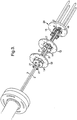
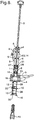
- FIG. 6 A second embodiment of the current invention is shown in Figure 6 .
- a single rod assembly 3 is used with a single large diameter screw thread 18.
- an adapter 27 which connects the rod assembly to the sample carrier assembly 2.
- an adapter 27 On the adapter there are a or a plurality of protrusions 28 that engage in slots or recesses 29 formed on the means 12 to allow the carrier to be thermally connected to the radiation shields.
- the sample is loaded into the carrier and entered through the gate valve 5 as per the first embodiment.
- the rod assembly is rotated to engage the protrusions 28 in the slots or recesses 28 and the rod assembly is then pushed towards the cryostat until the protrusions 28 meet an obstruction 30.
- Thermal connection is then optionally made through the protrusions or through optional spring contacts 31.
- the slot and obstruction are optional and serve to prevent the sample carrier from being accidentally pushed past the radiation shield prior to pre-cooling.
- the sample rod When the sample is cooled adequately, the sample rod is optionally retracted slightly and rotated to allow the protrusions 28 to move past the obstruction 30. The rod assembly can then be further inserted to allow it to be thermally connected to the next radiation shield if so required.
- the optional baffles 13 fitted with optional spring thermal contacts 14 engage in the assembly 12 so as to both close the port in the radiation shield and optionally to make thermal contact between the radiation shield and the rod assembly to intercept heat.
- a similar optional process for pre-cooling on subsequent radiation shield(s) can then be included before moving the sample to the cold body.
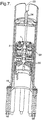
- Figure 7 shows a cross sectional view of the sample carrier assembly of the second embodiment engaged on the cold body.
- the sample carrier 2 is enclosed in a tube 32 with a screw thread 18 on one end.
- a means 33 of connecting the tube to the adapter on the end of the rod assembly is provided at the opposite end of the tube. This allows the tube to be inserted and retracted and to be rotated by the rod assembly.
- the sample carrier is free to rotate inside the tube and is thermally connected to the adapter at the end of the rod assembly using a spring thermal contact 34.
- the rod assembly is then rotated to pull the sample carrier on to the mating part, making the thermal contact and optional electrical and optical connections.
- the rod assembly can then be retracted from the cryostat, disconnecting at the means of connecting the tube to the adapter on the end of the rod assembly.
- Optional baffles can be fitted to close the ports in the radiation shields if the rod assembly is to be completely removed. Removal of the sample is essentially the reverse of the insertion process, with the exception that it is not usually necessary to leave the sample carrier at the radiation shields to warm up when retracting the sample.
- the mechanism for connection to the radiation shields from being a screw connection to being a spring connection
- the sample carrier is fitted with a or a plurality of thermally conductive springs which engage on an inner surface of the cut-out on the radiation shield. That inner surface may be extended, for example by addition of a tube assembly or a thicker plate assembly to allow for engagement.
- the thermal connection could be via springs at the higher temperature shields and via screw contact at the lower temperature shields or any combination thereof.
- Cone or wedge-shaped mating parts on either side of the releasable coupling could be used to amplify the contact pressure from the mounting mechanism. Pneumatic or piezo or other forms of releasable contact could also be used.
- connection to the or each cold body can optionally be via thermally conductive spring contacts rather than screw connection.
- connection to the radiation shields can optionally be via thermally conductive spring contacts or screw contacts.
- thermal connection is or could be made to a radiation shield or shield
- this thermal connection could alternatively be made to any other suitable cold surface.
- thermally conductive spring contacts these can be made from a single material, such as Berillium Copper, or may be made from a laminate or composite of different materials to provide both a good spring force and a high thermal conductivity.
- Dissimilar materials are preferred so as to reduce eddy currents and quench forces when used with a magnet. Examples of dissimilar materials could be copper for high thermal conductivity and stainless steel for high strength and lower electrical conductivity to reduce induced eddy currents.
- Other possibilities could include titanium and copper or brass and copper or alumium alloy and copper. Generically, it is one material of high thermal conductivity and one of high strength and higher resistance.
- the second material could also be a plastic or a composite.
- an additional port or plurality thereof can be added to the second vacuum vessel to allow the sample and optionally the sample carrier to be removed without removal of the second vacuum vessel from the main vacuum vessel.
- connection to the radiation shields it is possible to change the connection to the radiation shields to a screw thread on the outside of the rotating tube assembly. It is also possible to change the screw thread connection to the cold body to be an external thread, meaning the same thread can be used to connect to the radiation shields for pre-cooling and then to the cold body.
- the tube assembly with the thread may optionally have a split in it to allow the diameter to change to compensate for thermal expansion and contraction.
- a superconducting magnet could be located in the cryostat 50 as is known conventionally for dynamic nuclear polarisation and nuclear magnetic resonance and other cryogenic magnetic field applications.
- the rods form actuators for connecting and disconnecting to the cold bodies and are demountable from the cryostat.
- the rods (or other actuators) could form part of the cryostat and the sample carrier could be carried on a probe independent of the rods (or other actuators), the rods (or other actuators) being manipulated to engage the screw threads (or other connection mechanism) as before.
Landscapes
- Engineering & Computer Science (AREA)
- Physics & Mathematics (AREA)
- Mechanical Engineering (AREA)
- Thermal Sciences (AREA)
- General Engineering & Computer Science (AREA)
- Chemical & Material Sciences (AREA)
- Combustion & Propulsion (AREA)
- Sampling And Sample Adjustment (AREA)
- Separation By Low-Temperature Treatments (AREA)
Claims (15)
- Kryogenfreie Kühlvorrichtung, umfassend:Eine Vakuumkammer (4);ein erstes Wärmestrahlungsschild (54), das einen Arbeitsbereich (20) umgibt und in der Vakuumkammern (4) positioniert ist;ein kryogenfreies Kühlsystem, zum Beispiel ein mechanischer wie ein GM-Kühler, Stirling-Kühler oder ein Pulsröhrengerät, mit einer Kühlstufe, die an das erste Wärmestrahlungsschild (54) gekoppelt ist;einen kalten Körper (12), der von einer Oberfläche gebildet ist, die mit einer kalten Platte verbunden ist, die an eine Kühlstufe des Kühlsystems gekoppelt ist;einen kalten Montagekörper (15), der im Arbeitsbereich (20) positioniert ist und auf einer niedrigeren Temperatur als der kalte Körper (12) gehalten wird;ausgerichtete Öffnungen (52, 56) im ersten Wärmestrahlungsschild (54) und der Vakuumkammerwand;Probenladevorrichtung mit einer oder mehreren Sonden (3) und ein Probenhaltegerät (2), das an die eine oder mehrere der länglichen Sonden angebracht ist, die eine oder mehrere längliche Sonden zum Einführen des Haltegeräts durch die ausgerichteten Öffnungen (52, 56) in den Arbeitsbereich (20); undeinen thermischen Anschluss (18), wodurch das Probenhaltegerät (2) konfiguriert ist, über den Anschluss mit dem kalten Montagekörper (15) verbunden zu sein, und wobei die längliche Sonde oder jede der länglichen Sonden (3) lösbar an das Probenhaltegerät gekoppelt sind, um das Probehaltegerät freizugeben, wenn das Probenhaltegerät mit dem kalten Montagekörper verbunden ist;dadurch gekennzeichnet, dass das Probenhaltegerät (2) für Wärmeleitung über den Anschluss (18) lösbar an den kalten Körper (12) gekoppelt ist, um eine Probe (1) auf oder im Probenhaltegerät vorzukühlen, bevor das Probenhaltegerät an den kalten Montagekörper (15) angeschlossen wird.
- Vorrichtung nach Anspruch 1, wobei der kalte Körper durch das erste Wärmestrahlungsschild (54) gebildet wird, wodurch der Anschluss (18) lösbar für Wärmeleitung an das erste Wärmestrahlungsschild gekoppelt werden kann.
- Vorrichtung nach Anspruch 2, die ferner ein zweites Wärmestrahlungsschild (10) umfasst, das innerhalb des ersten Wärmeschilds (54) positioniert ist und den Arbeitsbereich (20) umgibt, wobei das kryogenfreie Kühlsystem eine zweite Kühlstufe aufweist, kälter als die erste Kühlstufe, die an das zweite Wärmestrahlungsschild gekoppelt ist, wobei das zweite Wärmeschild eine Öffnung (58) aufweist, die mit den Öffnungen (52, 56) des ersten Wärmestrahlungsschilds und der Vakuumkammerwand ausgerichtet ist, um dem Probenhaltegerät (2) zu erlauben dort hindurch zu gehen, wodurch das Probenhaltegerät für Wärmeleitung lösbar an das zweite Wärmestrahlungsschild gekoppelt werden kann.
- Vorrichtung nach Anspruch 3, wobei das erste Wärmestrahlungsschild (54) auf einer Temperatur von zwischen 45K und 90K gehalten wird und das zweite Wärmestrahlungsschild (10) vorzugsweise auf einer Temperatur von weniger als 6K gehalten wird.
- Vorrichtung nach einem der vorhergehenden Ansprüche, wobei die ausgerichtete Öffnung (52) in der Vakuumkammerwand ein Verschlusssystem (5) wie beispielsweise ein Vakuumventil einschließt.
- Vorrichtung nach einem der vorhergehenden Ansprüche, wobei die oder jede ausgerichtete Öffnung (56, 58) im ersten Wärmestrahlungsschild (54) und zweiten Wärmestrahlungsschild (10) durch ein jeweiliges Verschlusssystem (25), wie beispielsweise eine oder mehrere flexible Klappen oder scharnierte oder gefederte Klappen, schließbar ist.
- Vorrichtung nach einem der vorhergehenden Ansprüche, wobei die eine oder die mehreren länglichen Sonden (3) zwei oder mehrere längliche Sonden umfassen, wobei jede an das Probenhaltegerät gekoppelt ist.
- Vorrichtung nach Anspruch 7, wobei jede Sonde um ihre Achse relativ zum Probenhaltegerät (2) drehbar ist, und wobei die oder jede Sonde vorzugsweise an einem Ende mit einem Schraubengewinde (18) versehen ist, um den thermischen Anschluss zu definieren, wobei der Anschluss mit einem Schraubengewinde (19) am kalten Körper kooperiert, um eine thermische Verbindung dazwischen zu erzielen.
- Vorrichtung nach einem der Ansprüche 1 bis 7, wobei der thermische Anschluss eine oder mehrere thermisch leitfähige Federn umfasst, die typisch Verbundmaterial mit hoher thermischer Leitfähigkeit und hoher Federkraft umfassen, angebracht zur Herstellung von thermischem Kontakt zwischen dem kalten Körper und dem Probenhaltegerät (2).
- Vorrichtung nach Anspruch 3, wobei die Probenladevorrichtung relativ zur Vakuumkammer (4) und den ersten und zweiten Wärmeschildern (10, 54) drehbar ist, um sich selektiv mit dem oder jedem thermischen Anschluss (18) oder mit der jeweiligen Öffnung (52, 56, 58) auszurichten, um dem Probenhaltegerät (2) dort hindurch geleitet zu werden.
- Vorrichtung nach einem der vorhergehenden Ansprüche, wobei das Probenhaltegerät (2) einen oder mehrere elektrische Anschlüsse einschließt, um elektrische und thermische Anschlüsse zu einem kalten Körper (15) im Arbeitsbereich (20) herzustellen zu können.
- Vorrichtung nach einem der vorhergehenden Ansprüche, wobei das Probenhaltegerät (2) einen oder mehrere optische Anschlüsse, wie beispielsweise Glasfaseranschlüsse, einschließt, um elektrische und thermische Anschlüsse zu einem kalten Körper (15) im Arbeitsbereich (20) herzustellen zu können.
- Vorrichtung nach einem der vorhergehenden Ansprüche, wobei die Probenladevorrichtung ferner ein Vakuumgefäß (6) einschließt, in dem die Probenhaltevorrichtung (2) und die längliche(n) Sonde oder Sonden (3) verschiebbar montiert ist/sind, wobei das Vakuumgefäß an die Öffnung (52) der Vakuumkammerwand anschließbar ist.
- Verfahren zum Laden einer Probe (1) in den Arbeitsbereich (20) der kryogenfreien Kühlvorrichtung nach Ansprüchen 5 und 13, wobei das Verfahren umfasst:Platzieren einer Probe (1) in oder auf das Probenhaltegerät (2);Befestigen des Vakuumgefäßes (6) der Probenladevorrichtung an die Vakuumkammer (4) und ausgerichtet mit der Öffnung (52) der Vakuumkammer;Evakuieren des Vakuumgefäßes (6);Öffnen der Öffnung (52) der Vakuumkammer (4) und Betätigen der oder jeder länglichen Sonde (3), um das Probenhaltegerät (2) durch die geöffnete Öffnung einzuführen, sodass das Probenhaltegerät thermisch an den kalten Körper gekoppelt ist;Ermöglichen, dass die Probe (1) im oder auf dem Probenhaltegerät (2) infolge von Wärmeleitung zum kalten Körper gekühlt wird;Trennen des Probenhaltegeräts (2) vom kalten Körper; undBetätigen der oder jeder länglichen Sonde (3), um das Probenhaltegerät (2) in den Arbeitsbereich (20) einzuführen.
- Verfahren nach Anspruch 14, wobei die Vorrichtung ferner ein zweites Wärmestrahlungsschild (10) umfasst, das innerhalb des ersten Wärmestrahlungsschilds (54) positioniert ist und den Arbeitsbereich (20) umgibt, wobei das kryogenfreie Kühlsystem eine zweite Kühlstufe, kälter als die erste Kühlstufe, aufweist, die an das zweite Wärmestrahlungsschild gekoppelt ist, wobei das zweite Wärmestrahlungsschild eine Öffnung (58) aufweist, die mit den Öffnungen des ersten Wärmestrahlungsschilds und der Vakuumkammerwand (52, 54) ausgerichtet ist, um dem Probenhaltegerät (2) zu erlauben dort hindurch zu gehen, wodurch das Probenhaltegerät für Wärmeleitung lösbar an das zweite Wärmestrahlungsschild gekoppelt werden kann, und wobei vor dem Erreichen des Arbeitsbereichs, das Probenhaltegerät thermisch an das zweite Wärmestrahlungsschild gekoppelt wird, gekühlt durch Erlauben, dass Wärme zum zweiten Strahlungsschild, getrennt vom zweiten Strahlungsschild, fließt und das Probenhaltegerät danach in den Arbeitsbereich eingeführt wird.
Priority Applications (3)
| Application Number | Priority Date | Filing Date | Title |
|---|---|---|---|
| EP22154522.1A EP4027081B1 (de) | 2009-03-16 | 2010-03-15 | Vorrichtung und verfahren zur kryogenfreien kühlung |
| EP19187223.3A EP3620732B2 (de) | 2009-03-16 | 2010-03-15 | Vorrichtung und verfahren zur kryogenfreien kühlung |
| EP22205298.7A EP4148353B1 (de) | 2009-03-16 | 2010-03-15 | Kryogenfreie kühlvorrichtung und verfahren |
Applications Claiming Priority (2)
| Application Number | Priority Date | Filing Date | Title |
|---|---|---|---|
| GBGB0904500.6A GB0904500D0 (en) | 2009-03-16 | 2009-03-16 | Cryofree cooling apparatus and method |
| PCT/GB2010/000454 WO2010106309A2 (en) | 2009-03-16 | 2010-03-15 | Cryogen free cooling apparatus and method |
Related Child Applications (6)
| Application Number | Title | Priority Date | Filing Date |
|---|---|---|---|
| EP22154522.1A Division-Into EP4027081B1 (de) | 2009-03-16 | 2010-03-15 | Vorrichtung und verfahren zur kryogenfreien kühlung |
| EP22154522.1A Division EP4027081B1 (de) | 2009-03-16 | 2010-03-15 | Vorrichtung und verfahren zur kryogenfreien kühlung |
| EP19187223.3A Division-Into EP3620732B2 (de) | 2009-03-16 | 2010-03-15 | Vorrichtung und verfahren zur kryogenfreien kühlung |
| EP19187223.3A Division EP3620732B2 (de) | 2009-03-16 | 2010-03-15 | Vorrichtung und verfahren zur kryogenfreien kühlung |
| EP22205298.7A Division-Into EP4148353B1 (de) | 2009-03-16 | 2010-03-15 | Kryogenfreie kühlvorrichtung und verfahren |
| EP22205298.7A Division EP4148353B1 (de) | 2009-03-16 | 2010-03-15 | Kryogenfreie kühlvorrichtung und verfahren |
Publications (3)
| Publication Number | Publication Date |
|---|---|
| EP2409096A2 EP2409096A2 (de) | 2012-01-25 |
| EP2409096B1 true EP2409096B1 (de) | 2019-08-21 |
| EP2409096B2 EP2409096B2 (de) | 2024-06-19 |
Family
ID=40637422
Family Applications (4)
| Application Number | Title | Priority Date | Filing Date |
|---|---|---|---|
| EP19187223.3A Active EP3620732B2 (de) | 2009-03-16 | 2010-03-15 | Vorrichtung und verfahren zur kryogenfreien kühlung |
| EP22205298.7A Active EP4148353B1 (de) | 2009-03-16 | 2010-03-15 | Kryogenfreie kühlvorrichtung und verfahren |
| EP10710389.7A Active EP2409096B2 (de) | 2009-03-16 | 2010-03-15 | Kryogenfreie kühlvorrichtung und verfahren |
| EP22154522.1A Active EP4027081B1 (de) | 2009-03-16 | 2010-03-15 | Vorrichtung und verfahren zur kryogenfreien kühlung |
Family Applications Before (2)
| Application Number | Title | Priority Date | Filing Date |
|---|---|---|---|
| EP19187223.3A Active EP3620732B2 (de) | 2009-03-16 | 2010-03-15 | Vorrichtung und verfahren zur kryogenfreien kühlung |
| EP22205298.7A Active EP4148353B1 (de) | 2009-03-16 | 2010-03-15 | Kryogenfreie kühlvorrichtung und verfahren |
Family Applications After (1)
| Application Number | Title | Priority Date | Filing Date |
|---|---|---|---|
| EP22154522.1A Active EP4027081B1 (de) | 2009-03-16 | 2010-03-15 | Vorrichtung und verfahren zur kryogenfreien kühlung |
Country Status (7)
| Country | Link |
|---|---|
| US (1) | US20120102975A1 (de) |
| EP (4) | EP3620732B2 (de) |
| JP (1) | JP2012520987A (de) |
| ES (2) | ES2935698T3 (de) |
| FI (4) | FI4027081T3 (de) |
| GB (1) | GB0904500D0 (de) |
| WO (1) | WO2010106309A2 (de) |
Cited By (3)
| Publication number | Priority date | Publication date | Assignee | Title |
|---|---|---|---|---|
| WO2021229149A1 (en) | 2020-05-13 | 2021-11-18 | Bluefors Oy | Device and method for providing a thermally conductive coupling |
| EP4088068B1 (de) * | 2020-02-27 | 2023-10-11 | Oxford Instruments Nanotechnology Tools Limited | Kryogenes kühlsystem |
| EP4264288B1 (de) * | 2020-12-18 | 2025-04-30 | Microsoft Technology Licensing, LLC | Rf-funktionssonde |
Families Citing this family (14)
| Publication number | Priority date | Publication date | Assignee | Title |
|---|---|---|---|---|
| GB2493553B (en) * | 2011-08-11 | 2017-09-13 | Oxford Instr Nanotechnology Tools Ltd | Cryogenic cooling apparatus and method |
| CN102967834B (zh) * | 2012-11-23 | 2014-10-15 | 中国科学院武汉物理与数学研究所 | 一种磁共振引擎装置及方法 |
| WO2014102669A1 (en) * | 2012-12-27 | 2014-07-03 | Koninklijke Philips N.V. | System and method for quench protection of a cryo-free super conducting magnet |
| DE102015215919B4 (de) | 2015-08-20 | 2017-06-22 | Bruker Biospin Gmbh | Verfahren und Vorrichtung zur Vorkühlung eines Kryostaten |
| EP3163222B1 (de) | 2015-10-28 | 2018-07-18 | Technische Universität München | Kältemittelfreie kühlvorrichtung |
| CN109488720B (zh) * | 2018-12-27 | 2024-04-26 | 仪晟科学仪器(嘉兴)有限公司 | 闭循环液氦制冷机的机械隔离式震动屏蔽系统 |
| DE102019203341A1 (de) | 2019-03-12 | 2020-09-17 | Pressure Wave Systems Gmbh | Kryostat |
| EP3734303B1 (de) * | 2019-05-03 | 2024-04-03 | Afore Oy | Kryogener wafertester mit beladevorrichtung |
| US11630172B2 (en) * | 2021-03-15 | 2023-04-18 | Bruker Biospin Corp. | NMR magnet system with Stirling cooler |
| US20240159450A1 (en) * | 2021-03-16 | 2024-05-16 | L'air Liquide, Societe Anonyme Pour L'etude Et L'exploitation Des Procedes Georges Claude | Easy access via a partial lateral opening system |
| GB2616318B (en) | 2022-05-16 | 2024-05-15 | Oxford Instruments Nanotechnology Tools Ltd | Cryogenic cooling system |
| DE102023111606A1 (de) * | 2023-05-04 | 2024-11-07 | eleQtron GmbH | Vakuumkammer, Quantencomputeranordnung und Kühlverfahren |
| CN116951817B (zh) * | 2023-06-27 | 2025-09-30 | 南方科技大学 | 一种纺锤形低温预冷装置以及制冷机 |
| US20250380384A1 (en) * | 2024-06-07 | 2025-12-11 | International Business Machines Corporation | Quick-loading cryogenic cooling systems |
Citations (12)
| Publication number | Priority date | Publication date | Assignee | Title |
|---|---|---|---|---|
| US4251123A (en) | 1979-05-04 | 1981-02-17 | The United States Of America As Represented By The United States Department Of Energy | Glove box shield |
| US4872321A (en) | 1988-04-27 | 1989-10-10 | Biomagnetic Technologies, Inc. | Nonimmersive cryogenic cooler |
| US5611207A (en) | 1995-06-29 | 1997-03-18 | Hess; John | Cryogenic interface for perpendicular loading of independent measurement inserts |
| US20040108067A1 (en) | 2002-08-02 | 2004-06-10 | Fischione Paul E. | Method and apparatus for preparing specimens for microscopy |
| US20050229620A1 (en) | 2004-04-15 | 2005-10-20 | Oxford Instruments Superconductivity Ltd. | Cooling apparatus |
| US20070096740A1 (en) | 2005-07-29 | 2007-05-03 | Yuzo Fukuda | Low temperature probe for NMR and NMR device |
| WO2007101305A1 (en) | 2006-03-07 | 2007-09-13 | Cambridge Magnetic Refrigeration Limited | Low temperature heatsinking system |
| US20070234751A1 (en) | 2006-04-06 | 2007-10-11 | National Institute Of Advanced Industrial Science And Technology | Sample cooling apparatus |
| JP2008014878A (ja) * | 2006-07-07 | 2008-01-24 | Kyushu Univ | クライオスタット及び試料装着装置、温度制御方法 |
| US20080104968A1 (en) | 2006-10-10 | 2008-05-08 | Massachusetts Institute Of Technology | Cryogenic vacuum break thermal coupler |
| JP2009074774A (ja) | 2007-09-25 | 2009-04-09 | Kyushu Univ | 無冷媒冷凍機及び機能性熱結合体 |
| WO2010002245A2 (en) | 2008-07-03 | 2010-01-07 | Giorgio Frossati | Holder for a sample to be cooled to a low temperature in a vacuum space and 3he-4he dilution refrigerator adapted to accommodate such a holder |
Family Cites Families (19)
| Publication number | Priority date | Publication date | Assignee | Title |
|---|---|---|---|---|
| US9027A (en) * | 1852-06-15 | Improvement in preparations of archil | ||
| US4446702A (en) | 1983-02-14 | 1984-05-08 | Helix Technology Corporation | Multiport cryopump |
| US4577465A (en) | 1984-05-11 | 1986-03-25 | Helix Technology Corporation | Oil free vacuum system |
| JPS60260833A (ja) * | 1984-06-07 | 1985-12-24 | Hoxan Corp | クライオスタツト |
| JPS6270461U (de) * | 1985-10-21 | 1987-05-02 | ||
| US5077523A (en) | 1989-11-03 | 1991-12-31 | John H. Blanz Company, Inc. | Cryogenic probe station having movable chuck accomodating variable thickness probe cards |
| JP2821241B2 (ja) * | 1990-06-08 | 1998-11-05 | 株式会社日立製作所 | 液化冷凍機付きクライオスタツト |
| US5237825A (en) * | 1991-11-08 | 1993-08-24 | Gte Laboratories Incorporated | Method and apparatus for cryogenically cooling samples |
| JP2946195B2 (ja) | 1995-08-18 | 1999-09-06 | セイコーインスツルメンツ株式会社 | 非破壊検査装置 |
| US5727392A (en) | 1996-12-19 | 1998-03-17 | Helix Technology Corporation | Convection-shielded cryopump |
| US5806319A (en) | 1997-03-13 | 1998-09-15 | Wary; John | Method and apparatus for cryogenically cooling a deposition chamber |
| JPH11162269A (ja) * | 1997-11-27 | 1999-06-18 | Toshiba Corp | 超電導機器 |
| JP2001255252A (ja) | 2000-03-10 | 2001-09-21 | Jeol Ltd | 試料搬送装置 |
| JP3580531B2 (ja) | 2000-04-20 | 2004-10-27 | 大陽東洋酸素株式会社 | 希釈冷凍機 |
| JP4163447B2 (ja) | 2002-05-22 | 2008-10-08 | 日本電子株式会社 | スキャナ保持装置および走査型プローブ顕微鏡 |
| JP2008098415A (ja) * | 2006-10-12 | 2008-04-24 | Toshiba Corp | 超電導機器 |
| US8082741B2 (en) | 2007-05-15 | 2011-12-27 | Brooks Automation, Inc. | Integral facet cryopump, water vapor pump, or high vacuum pump |
| DE102007028865B3 (de) * | 2007-06-22 | 2009-01-29 | Vericold Technologies Gmbh | Tieftemperaturvorrichtung |
| US8291717B2 (en) * | 2008-05-02 | 2012-10-23 | Massachusetts Institute Of Technology | Cryogenic vacuum break thermal coupler with cross-axial actuation |
-
2009
- 2009-03-16 GB GBGB0904500.6A patent/GB0904500D0/en not_active Ceased
-
2010
- 2010-03-15 EP EP19187223.3A patent/EP3620732B2/de active Active
- 2010-03-15 EP EP22205298.7A patent/EP4148353B1/de active Active
- 2010-03-15 WO PCT/GB2010/000454 patent/WO2010106309A2/en not_active Ceased
- 2010-03-15 FI FIEP22154522.1T patent/FI4027081T3/fi active
- 2010-03-15 FI FIEP10710389.7T patent/FI2409096T4/fi active
- 2010-03-15 EP EP10710389.7A patent/EP2409096B2/de active Active
- 2010-03-15 ES ES22154522T patent/ES2935698T3/es active Active
- 2010-03-15 US US13/257,032 patent/US20120102975A1/en not_active Abandoned
- 2010-03-15 JP JP2012500303A patent/JP2012520987A/ja active Pending
- 2010-03-15 FI FIEP19187223.3T patent/FI3620732T4/fi active
- 2010-03-15 EP EP22154522.1A patent/EP4027081B1/de active Active
- 2010-03-15 FI FIEP22205298.7T patent/FI4148353T1/fi unknown
- 2010-03-15 ES ES19187223T patent/ES2909009T5/es active Active
Patent Citations (12)
| Publication number | Priority date | Publication date | Assignee | Title |
|---|---|---|---|---|
| US4251123A (en) | 1979-05-04 | 1981-02-17 | The United States Of America As Represented By The United States Department Of Energy | Glove box shield |
| US4872321A (en) | 1988-04-27 | 1989-10-10 | Biomagnetic Technologies, Inc. | Nonimmersive cryogenic cooler |
| US5611207A (en) | 1995-06-29 | 1997-03-18 | Hess; John | Cryogenic interface for perpendicular loading of independent measurement inserts |
| US20040108067A1 (en) | 2002-08-02 | 2004-06-10 | Fischione Paul E. | Method and apparatus for preparing specimens for microscopy |
| US20050229620A1 (en) | 2004-04-15 | 2005-10-20 | Oxford Instruments Superconductivity Ltd. | Cooling apparatus |
| US20070096740A1 (en) | 2005-07-29 | 2007-05-03 | Yuzo Fukuda | Low temperature probe for NMR and NMR device |
| WO2007101305A1 (en) | 2006-03-07 | 2007-09-13 | Cambridge Magnetic Refrigeration Limited | Low temperature heatsinking system |
| US20070234751A1 (en) | 2006-04-06 | 2007-10-11 | National Institute Of Advanced Industrial Science And Technology | Sample cooling apparatus |
| JP2008014878A (ja) * | 2006-07-07 | 2008-01-24 | Kyushu Univ | クライオスタット及び試料装着装置、温度制御方法 |
| US20080104968A1 (en) | 2006-10-10 | 2008-05-08 | Massachusetts Institute Of Technology | Cryogenic vacuum break thermal coupler |
| JP2009074774A (ja) | 2007-09-25 | 2009-04-09 | Kyushu Univ | 無冷媒冷凍機及び機能性熱結合体 |
| WO2010002245A2 (en) | 2008-07-03 | 2010-01-07 | Giorgio Frossati | Holder for a sample to be cooled to a low temperature in a vacuum space and 3he-4he dilution refrigerator adapted to accommodate such a holder |
Non-Patent Citations (4)
| Title |
|---|
| H-P. BAUM ET AL.: "Top-Loading Dilution Refrigerator for High Frequency Measurements , Proc. 18th Int. Conf. on Low Temperature Physics", JAPANESE JOURNAL OF APPLIED PHYSICS, vol. 26, 1987, Kyoto, XP055482035 |
| J.E.RIX ET AL.: "Automated sample exchange and tracking system for neutron research at cryogenic temperatures", REVIEW OF SCIENTIFIC INSTRUMENTS, vol. 78, 2007, XP012103606, DOI: 10.1063/1.2426878 |
| J.H.FERRIS ET AL.: "Design, operation, and housing of an ultrastable, low temperature, ultrahigh vacuum scanning tunneling microscope", REVIEW OF SCIENTIFIC INSTRUMENTS, vol. 69, no. 7, July 1998 (1998-07-01), XP012036673, DOI: 10.1063/1.1149000 |
| LOU SANTODONATO: "Automated Sample Tracking and Exchange for Neutron Diffraction at Cryogenic Temperatures", ICANS-XVIII, 26 April 2007 (2007-04-26), Dongguan, China, XP055705287 |
Cited By (7)
| Publication number | Priority date | Publication date | Assignee | Title |
|---|---|---|---|---|
| EP4088068B1 (de) * | 2020-02-27 | 2023-10-11 | Oxford Instruments Nanotechnology Tools Limited | Kryogenes kühlsystem |
| EP4246064B1 (de) * | 2020-02-27 | 2024-10-30 | Oxford Instruments Nanotechnology Tools Limited | Kryogenes kühlsystem |
| WO2021229149A1 (en) | 2020-05-13 | 2021-11-18 | Bluefors Oy | Device and method for providing a thermally conductive coupling |
| US12013170B2 (en) | 2020-05-13 | 2024-06-18 | Bluefors Oy | Device and method for providing a thermally conductive coupling |
| EP4150272B1 (de) * | 2020-05-13 | 2024-07-10 | Bluefors Oy | Kryostat |
| EP4403849A2 (de) | 2020-05-13 | 2024-07-24 | Bluefors Oy | Kryostat |
| EP4264288B1 (de) * | 2020-12-18 | 2025-04-30 | Microsoft Technology Licensing, LLC | Rf-funktionssonde |
Also Published As
| Publication number | Publication date |
|---|---|
| JP2012520987A (ja) | 2012-09-10 |
| EP2409096B2 (de) | 2024-06-19 |
| US20120102975A1 (en) | 2012-05-03 |
| EP4148353B1 (de) | 2024-05-22 |
| EP4148353C0 (de) | 2024-05-22 |
| EP4027081B1 (de) | 2022-12-21 |
| EP3620732A1 (de) | 2020-03-11 |
| FI2409096T4 (fi) | 2024-06-20 |
| FI4027081T3 (fi) | 2023-01-13 |
| WO2010106309A8 (en) | 2011-10-13 |
| EP4027081A2 (de) | 2022-07-13 |
| EP4027081A3 (de) | 2022-08-31 |
| EP2409096A2 (de) | 2012-01-25 |
| WO2010106309A2 (en) | 2010-09-23 |
| WO2010106309A3 (en) | 2011-05-19 |
| ES2909009T3 (es) | 2022-05-04 |
| ES2909009T5 (en) | 2025-02-10 |
| GB0904500D0 (en) | 2009-04-29 |
| FI4148353T1 (fi) | 2023-03-29 |
| EP3620732B1 (de) | 2022-02-16 |
| ES2935698T3 (es) | 2023-03-09 |
| FI3620732T4 (fi) | 2024-11-22 |
| EP4148353A1 (de) | 2023-03-15 |
| EP3620732B2 (de) | 2024-10-09 |
Similar Documents
| Publication | Publication Date | Title |
|---|---|---|
| EP2409096B1 (de) | Kryogenfreie kühlvorrichtung und verfahren | |
| DK2742299T3 (en) | CRYOGEN REFRIGERATOR AND PROCEDURE | |
| EP3282269B1 (de) | Nmr-apparatur mit durch eine vakuumschleuse in den kryostaten einer supraleitenden magnetanordnung einführbaren gekühlten probenkopfkomponenten sowie verfahren zu deren ein- und ausbau | |
| DE102016214731B3 (de) | NMR-Apparatur mit supraleitender Magnetanordnung sowie gekühlten Probenkopfkomponenten | |
| EP1760480A1 (de) | NMR-Apparatur mit gemeinsam gekühltem Probenkopf und Kryobehälter | |
| JP2019502888A (ja) | 無寒剤冷却装置 | |
| US20010013818A1 (en) | Magnetizing magnet | |
| US20250012685A1 (en) | Refrigeration system and method for loading such a refrigeration system | |
| Pagliarone et al. | The cuore fast cooling system | |
| US20250380384A1 (en) | Quick-loading cryogenic cooling systems | |
| DE19813211A1 (de) | Supraleitende Einrichtung mit Leitern aus Hoch-Tc-Supraleitermaterial | |
| Teleberg et al. | Sample loading and accelerated cooling of cryogen-free dilution refrigerators | |
| Steinmeyer et al. | Towards the invisible cryogenic system for magnetic resonance imaging | |
| Hollister | Cryostat Options for 9.4 Tesla x 800 mm Solenoid | |
| GB2339889A (en) | Magnetising a superconductor at cryogenic temperatures | |
| Holmes et al. | A Sub-Kelvin Cooler for the Background Limited Infrared Submillimeter Spectrometer BLISS on SPICA | |
| Shirron et al. | A Rapid Turnaround Two‐Stage Adiabatic Demagnetization Refrigerator for Cooling to 50 mK |
Legal Events
| Date | Code | Title | Description |
|---|---|---|---|
| PUAI | Public reference made under article 153(3) epc to a published international application that has entered the european phase |
Free format text: ORIGINAL CODE: 0009012 |
|
| 17P | Request for examination filed |
Effective date: 20111006 |
|
| AK | Designated contracting states |
Kind code of ref document: A2 Designated state(s): AT BE BG CH CY CZ DE DK EE ES FI FR GB GR HR HU IE IS IT LI LT LU LV MC MK MT NL NO PL PT RO SE SI SK SM TR |
|
| DAX | Request for extension of the european patent (deleted) | ||
| TPAC | Observations filed by third parties |
Free format text: ORIGINAL CODE: EPIDOSNTIPA |
|
| STAA | Information on the status of an ep patent application or granted ep patent |
Free format text: STATUS: EXAMINATION IS IN PROGRESS |
|
| 17Q | First examination report despatched |
Effective date: 20170915 |
|
| GRAP | Despatch of communication of intention to grant a patent |
Free format text: ORIGINAL CODE: EPIDOSNIGR1 |
|
| STAA | Information on the status of an ep patent application or granted ep patent |
Free format text: STATUS: GRANT OF PATENT IS INTENDED |
|
| INTG | Intention to grant announced |
Effective date: 20190320 |
|
| RIN1 | Information on inventor provided before grant (corrected) |
Inventor name: GARSIDE, JOHN Inventor name: KINGLEY, SIMON Inventor name: CROWTHER, GAVIN Inventor name: WERNICKE, DOREEN Inventor name: BUEHLER, MATTHIAS |
|
| GRAS | Grant fee paid |
Free format text: ORIGINAL CODE: EPIDOSNIGR3 |
|
| GRAA | (expected) grant |
Free format text: ORIGINAL CODE: 0009210 |
|
| STAA | Information on the status of an ep patent application or granted ep patent |
Free format text: STATUS: THE PATENT HAS BEEN GRANTED |
|
| AK | Designated contracting states |
Kind code of ref document: B1 Designated state(s): AT BE BG CH CY CZ DE DK EE ES FI FR GB GR HR HU IE IS IT LI LT LU LV MC MK MT NL NO PL PT RO SE SI SK SM TR |
|
| REG | Reference to a national code |
Ref country code: GB Ref legal event code: FG4D |
|
| REG | Reference to a national code |
Ref country code: CH Ref legal event code: EP |
|
| REG | Reference to a national code |
Ref country code: DE Ref legal event code: R096 Ref document number: 602010060646 Country of ref document: DE |
|
| REG | Reference to a national code |
Ref country code: AT Ref legal event code: REF Ref document number: 1170228 Country of ref document: AT Kind code of ref document: T Effective date: 20190915 |
|
| REG | Reference to a national code |
Ref country code: IE Ref legal event code: FG4D |
|
| REG | Reference to a national code |
Ref country code: NL Ref legal event code: FP |
|
| REG | Reference to a national code |
Ref country code: LT Ref legal event code: MG4D |
|
| PG25 | Lapsed in a contracting state [announced via postgrant information from national office to epo] |
Ref country code: HR Free format text: LAPSE BECAUSE OF FAILURE TO SUBMIT A TRANSLATION OF THE DESCRIPTION OR TO PAY THE FEE WITHIN THE PRESCRIBED TIME-LIMIT Effective date: 20190821 Ref country code: LT Free format text: LAPSE BECAUSE OF FAILURE TO SUBMIT A TRANSLATION OF THE DESCRIPTION OR TO PAY THE FEE WITHIN THE PRESCRIBED TIME-LIMIT Effective date: 20190821 Ref country code: SE Free format text: LAPSE BECAUSE OF FAILURE TO SUBMIT A TRANSLATION OF THE DESCRIPTION OR TO PAY THE FEE WITHIN THE PRESCRIBED TIME-LIMIT Effective date: 20190821 Ref country code: BG Free format text: LAPSE BECAUSE OF FAILURE TO SUBMIT A TRANSLATION OF THE DESCRIPTION OR TO PAY THE FEE WITHIN THE PRESCRIBED TIME-LIMIT Effective date: 20191121 Ref country code: PT Free format text: LAPSE BECAUSE OF FAILURE TO SUBMIT A TRANSLATION OF THE DESCRIPTION OR TO PAY THE FEE WITHIN THE PRESCRIBED TIME-LIMIT Effective date: 20191223 Ref country code: NO Free format text: LAPSE BECAUSE OF FAILURE TO SUBMIT A TRANSLATION OF THE DESCRIPTION OR TO PAY THE FEE WITHIN THE PRESCRIBED TIME-LIMIT Effective date: 20191121 |
|
| PG25 | Lapsed in a contracting state [announced via postgrant information from national office to epo] |
Ref country code: IS Free format text: LAPSE BECAUSE OF FAILURE TO SUBMIT A TRANSLATION OF THE DESCRIPTION OR TO PAY THE FEE WITHIN THE PRESCRIBED TIME-LIMIT Effective date: 20191221 Ref country code: LV Free format text: LAPSE BECAUSE OF FAILURE TO SUBMIT A TRANSLATION OF THE DESCRIPTION OR TO PAY THE FEE WITHIN THE PRESCRIBED TIME-LIMIT Effective date: 20190821 Ref country code: ES Free format text: LAPSE BECAUSE OF FAILURE TO SUBMIT A TRANSLATION OF THE DESCRIPTION OR TO PAY THE FEE WITHIN THE PRESCRIBED TIME-LIMIT Effective date: 20190821 Ref country code: GR Free format text: LAPSE BECAUSE OF FAILURE TO SUBMIT A TRANSLATION OF THE DESCRIPTION OR TO PAY THE FEE WITHIN THE PRESCRIBED TIME-LIMIT Effective date: 20191122 |
|
| REG | Reference to a national code |
Ref country code: AT Ref legal event code: MK05 Ref document number: 1170228 Country of ref document: AT Kind code of ref document: T Effective date: 20190821 |
|
| PG25 | Lapsed in a contracting state [announced via postgrant information from national office to epo] |
Ref country code: TR Free format text: LAPSE BECAUSE OF FAILURE TO SUBMIT A TRANSLATION OF THE DESCRIPTION OR TO PAY THE FEE WITHIN THE PRESCRIBED TIME-LIMIT Effective date: 20190821 |
|
| PG25 | Lapsed in a contracting state [announced via postgrant information from national office to epo] |
Ref country code: AT Free format text: LAPSE BECAUSE OF FAILURE TO SUBMIT A TRANSLATION OF THE DESCRIPTION OR TO PAY THE FEE WITHIN THE PRESCRIBED TIME-LIMIT Effective date: 20190821 Ref country code: PL Free format text: LAPSE BECAUSE OF FAILURE TO SUBMIT A TRANSLATION OF THE DESCRIPTION OR TO PAY THE FEE WITHIN THE PRESCRIBED TIME-LIMIT Effective date: 20190821 Ref country code: DK Free format text: LAPSE BECAUSE OF FAILURE TO SUBMIT A TRANSLATION OF THE DESCRIPTION OR TO PAY THE FEE WITHIN THE PRESCRIBED TIME-LIMIT Effective date: 20190821 Ref country code: EE Free format text: LAPSE BECAUSE OF FAILURE TO SUBMIT A TRANSLATION OF THE DESCRIPTION OR TO PAY THE FEE WITHIN THE PRESCRIBED TIME-LIMIT Effective date: 20190821 Ref country code: RO Free format text: LAPSE BECAUSE OF FAILURE TO SUBMIT A TRANSLATION OF THE DESCRIPTION OR TO PAY THE FEE WITHIN THE PRESCRIBED TIME-LIMIT Effective date: 20190821 Ref country code: IT Free format text: LAPSE BECAUSE OF FAILURE TO SUBMIT A TRANSLATION OF THE DESCRIPTION OR TO PAY THE FEE WITHIN THE PRESCRIBED TIME-LIMIT Effective date: 20190821 |
|
| PG25 | Lapsed in a contracting state [announced via postgrant information from national office to epo] |
Ref country code: SM Free format text: LAPSE BECAUSE OF FAILURE TO SUBMIT A TRANSLATION OF THE DESCRIPTION OR TO PAY THE FEE WITHIN THE PRESCRIBED TIME-LIMIT Effective date: 20190821 Ref country code: SK Free format text: LAPSE BECAUSE OF FAILURE TO SUBMIT A TRANSLATION OF THE DESCRIPTION OR TO PAY THE FEE WITHIN THE PRESCRIBED TIME-LIMIT Effective date: 20190821 Ref country code: IS Free format text: LAPSE BECAUSE OF FAILURE TO SUBMIT A TRANSLATION OF THE DESCRIPTION OR TO PAY THE FEE WITHIN THE PRESCRIBED TIME-LIMIT Effective date: 20200224 Ref country code: CZ Free format text: LAPSE BECAUSE OF FAILURE TO SUBMIT A TRANSLATION OF THE DESCRIPTION OR TO PAY THE FEE WITHIN THE PRESCRIBED TIME-LIMIT Effective date: 20190821 |
|
| REG | Reference to a national code |
Ref country code: DE Ref legal event code: R026 Ref document number: 602010060646 Country of ref document: DE |
|
| PLBI | Opposition filed |
Free format text: ORIGINAL CODE: 0009260 |
|
| PLAX | Notice of opposition and request to file observation + time limit sent |
Free format text: ORIGINAL CODE: EPIDOSNOBS2 |
|
| REG | Reference to a national code |
Ref country code: FI Ref legal event code: MDE Opponent name: BLUEFORS OY |
|
| 26 | Opposition filed |
Opponent name: BLUEFORS OY Effective date: 20200601 |
|
| PG2D | Information on lapse in contracting state deleted |
Ref country code: IS |
|
| PG25 | Lapsed in a contracting state [announced via postgrant information from national office to epo] |
Ref country code: SI Free format text: LAPSE BECAUSE OF FAILURE TO SUBMIT A TRANSLATION OF THE DESCRIPTION OR TO PAY THE FEE WITHIN THE PRESCRIBED TIME-LIMIT Effective date: 20190821 |
|
| PG25 | Lapsed in a contracting state [announced via postgrant information from national office to epo] |
Ref country code: MC Free format text: LAPSE BECAUSE OF FAILURE TO SUBMIT A TRANSLATION OF THE DESCRIPTION OR TO PAY THE FEE WITHIN THE PRESCRIBED TIME-LIMIT Effective date: 20190821 |
|
| REG | Reference to a national code |
Ref country code: CH Ref legal event code: PL |
|
| PLBB | Reply of patent proprietor to notice(s) of opposition received |
Free format text: ORIGINAL CODE: EPIDOSNOBS3 |
|
| REG | Reference to a national code |
Ref country code: BE Ref legal event code: MM Effective date: 20200331 |
|
| PG25 | Lapsed in a contracting state [announced via postgrant information from national office to epo] |
Ref country code: LU Free format text: LAPSE BECAUSE OF NON-PAYMENT OF DUE FEES Effective date: 20200315 |
|
| PG25 | Lapsed in a contracting state [announced via postgrant information from national office to epo] |
Ref country code: LI Free format text: LAPSE BECAUSE OF NON-PAYMENT OF DUE FEES Effective date: 20200331 Ref country code: IE Free format text: LAPSE BECAUSE OF NON-PAYMENT OF DUE FEES Effective date: 20200315 Ref country code: FR Free format text: LAPSE BECAUSE OF NON-PAYMENT OF DUE FEES Effective date: 20200331 Ref country code: CH Free format text: LAPSE BECAUSE OF NON-PAYMENT OF DUE FEES Effective date: 20200331 |
|
| PG25 | Lapsed in a contracting state [announced via postgrant information from national office to epo] |
Ref country code: BE Free format text: LAPSE BECAUSE OF NON-PAYMENT OF DUE FEES Effective date: 20200331 |
|
| APBM | Appeal reference recorded |
Free format text: ORIGINAL CODE: EPIDOSNREFNO |
|
| APBP | Date of receipt of notice of appeal recorded |
Free format text: ORIGINAL CODE: EPIDOSNNOA2O |
|
| APAH | Appeal reference modified |
Free format text: ORIGINAL CODE: EPIDOSCREFNO |
|
| APBM | Appeal reference recorded |
Free format text: ORIGINAL CODE: EPIDOSNREFNO |
|
| APBP | Date of receipt of notice of appeal recorded |
Free format text: ORIGINAL CODE: EPIDOSNNOA2O |
|
| PG25 | Lapsed in a contracting state [announced via postgrant information from national office to epo] |
Ref country code: MT Free format text: LAPSE BECAUSE OF FAILURE TO SUBMIT A TRANSLATION OF THE DESCRIPTION OR TO PAY THE FEE WITHIN THE PRESCRIBED TIME-LIMIT Effective date: 20190821 Ref country code: CY Free format text: LAPSE BECAUSE OF FAILURE TO SUBMIT A TRANSLATION OF THE DESCRIPTION OR TO PAY THE FEE WITHIN THE PRESCRIBED TIME-LIMIT Effective date: 20190821 |
|
| PG25 | Lapsed in a contracting state [announced via postgrant information from national office to epo] |
Ref country code: MK Free format text: LAPSE BECAUSE OF FAILURE TO SUBMIT A TRANSLATION OF THE DESCRIPTION OR TO PAY THE FEE WITHIN THE PRESCRIBED TIME-LIMIT Effective date: 20190821 |
|
| P01 | Opt-out of the competence of the unified patent court (upc) registered |
Effective date: 20230516 |
|
| APBU | Appeal procedure closed |
Free format text: ORIGINAL CODE: EPIDOSNNOA9O |
|
| PGFP | Annual fee paid to national office [announced via postgrant information from national office to epo] |
Ref country code: NL Payment date: 20240226 Year of fee payment: 15 |
|
| PGFP | Annual fee paid to national office [announced via postgrant information from national office to epo] |
Ref country code: FI Payment date: 20240315 Year of fee payment: 15 Ref country code: DE Payment date: 20240220 Year of fee payment: 15 Ref country code: GB Payment date: 20240222 Year of fee payment: 15 |
|
| PUAH | Patent maintained in amended form |
Free format text: ORIGINAL CODE: 0009272 |
|
| STAA | Information on the status of an ep patent application or granted ep patent |
Free format text: STATUS: PATENT MAINTAINED AS AMENDED |
|
| 27A | Patent maintained in amended form |
Effective date: 20240619 |
|
| AK | Designated contracting states |
Kind code of ref document: B2 Designated state(s): AT BE BG CH CY CZ DE DK EE ES FI FR GB GR HR HU IE IS IT LI LT LU LV MC MK MT NL NO PL PT RO SE SI SK SM TR |
|
| REG | Reference to a national code |
Ref country code: DE Ref legal event code: R102 Ref document number: 602010060646 Country of ref document: DE |
|
| REG | Reference to a national code |
Ref country code: NL Ref legal event code: FP |
|
| REG | Reference to a national code |
Ref country code: NL Ref legal event code: PD Owner name: OXFORD NANOSCIENCE LIMITED; GB Free format text: DETAILS ASSIGNMENT: CHANGE OF OWNER(S), ASSIGNMENT; FORMER OWNER NAME: OXFORD INSTRUMENTS NANOTECHNOLOGY TOOLS LIMITED Effective date: 20250815 |
|
| REG | Reference to a national code |
Ref country code: GB Ref legal event code: 732E Free format text: REGISTERED BETWEEN 20250828 AND 20250903 |
|
| REG | Reference to a national code |
Ref country code: DE Ref legal event code: R119 Ref document number: 602010060646 Country of ref document: DE |
|
| PG25 | Lapsed in a contracting state [announced via postgrant information from national office to epo] |
Ref country code: FI Free format text: LAPSE BECAUSE OF NON-PAYMENT OF DUE FEES Effective date: 20250315 |
|
| REG | Reference to a national code |
Ref country code: NL Ref legal event code: MM Effective date: 20250401 |
|
| GBPC | Gb: european patent ceased through non-payment of renewal fee |
Effective date: 20250315 |
|
| PG25 | Lapsed in a contracting state [announced via postgrant information from national office to epo] |
Ref country code: NL Free format text: LAPSE BECAUSE OF NON-PAYMENT OF DUE FEES Effective date: 20250401 |
|
| PG25 | Lapsed in a contracting state [announced via postgrant information from national office to epo] |
Ref country code: DE Free format text: LAPSE BECAUSE OF NON-PAYMENT OF DUE FEES Effective date: 20251001 |
|
| PG25 | Lapsed in a contracting state [announced via postgrant information from national office to epo] |
Ref country code: GB Free format text: LAPSE BECAUSE OF NON-PAYMENT OF DUE FEES Effective date: 20250315 |
|
| REG | Reference to a national code |
Ref country code: DE Ref legal event code: R081 Ref document number: 602010060646 Country of ref document: DE Owner name: OXFORD NANOSCIENCE LIMITED, ABINGDON, GB Free format text: FORMER OWNER: OXFORD INSTRUMENTS NANOTECHNOLOGY TOOLS LIMITED, ABINGDON, OXON, GB |
|
| REG | Reference to a national code |
Ref country code: FI Ref legal event code: PCE Owner name: OXFORD NANOSCIENCE LIMITED |