EP4152006B1 - Automatische analysevorrichtung - Google Patents
Automatische analysevorrichtung Download PDFInfo
- Publication number
- EP4152006B1 EP4152006B1 EP21802189.7A EP21802189A EP4152006B1 EP 4152006 B1 EP4152006 B1 EP 4152006B1 EP 21802189 A EP21802189 A EP 21802189A EP 4152006 B1 EP4152006 B1 EP 4152006B1
- Authority
- EP
- European Patent Office
- Prior art keywords
- reaction vessel
- incubator
- hole
- lubricating member
- automatic analyzer
- Prior art date
- Legal status (The legal status is an assumption and is not a legal conclusion. Google has not performed a legal analysis and makes no representation as to the accuracy of the status listed.)
- Active
Links
Images






Classifications
-
- G—PHYSICS
- G01—MEASURING; TESTING
- G01N—INVESTIGATING OR ANALYSING MATERIALS BY DETERMINING THEIR CHEMICAL OR PHYSICAL PROPERTIES
- G01N35/00—Automatic analysis not limited to methods or materials provided for in any single one of groups G01N1/00 - G01N33/00; Handling materials therefor
-
- G—PHYSICS
- G01—MEASURING; TESTING
- G01N—INVESTIGATING OR ANALYSING MATERIALS BY DETERMINING THEIR CHEMICAL OR PHYSICAL PROPERTIES
- G01N35/00—Automatic analysis not limited to methods or materials provided for in any single one of groups G01N1/00 - G01N33/00; Handling materials therefor
- G01N35/02—Automatic analysis not limited to methods or materials provided for in any single one of groups G01N1/00 - G01N33/00; Handling materials therefor using a plurality of sample containers moved by a conveyor system past one or more treatment or analysis stations
- G01N35/026—Automatic analysis not limited to methods or materials provided for in any single one of groups G01N1/00 - G01N33/00; Handling materials therefor using a plurality of sample containers moved by a conveyor system past one or more treatment or analysis stations having blocks or racks of reaction cells or cuvettes
-
- G—PHYSICS
- G01—MEASURING; TESTING
- G01N—INVESTIGATING OR ANALYSING MATERIALS BY DETERMINING THEIR CHEMICAL OR PHYSICAL PROPERTIES
- G01N35/00—Automatic analysis not limited to methods or materials provided for in any single one of groups G01N1/00 - G01N33/00; Handling materials therefor
- G01N35/0099—Automatic analysis not limited to methods or materials provided for in any single one of groups G01N1/00 - G01N33/00; Handling materials therefor comprising robots or similar manipulators
-
- G—PHYSICS
- G01—MEASURING; TESTING
- G01N—INVESTIGATING OR ANALYSING MATERIALS BY DETERMINING THEIR CHEMICAL OR PHYSICAL PROPERTIES
- G01N35/00—Automatic analysis not limited to methods or materials provided for in any single one of groups G01N1/00 - G01N33/00; Handling materials therefor
- G01N35/02—Automatic analysis not limited to methods or materials provided for in any single one of groups G01N1/00 - G01N33/00; Handling materials therefor using a plurality of sample containers moved by a conveyor system past one or more treatment or analysis stations
- G01N35/025—Automatic analysis not limited to methods or materials provided for in any single one of groups G01N1/00 - G01N33/00; Handling materials therefor using a plurality of sample containers moved by a conveyor system past one or more treatment or analysis stations having a carousel or turntable for reaction cells or cuvettes
-
- G—PHYSICS
- G01—MEASURING; TESTING
- G01N—INVESTIGATING OR ANALYSING MATERIALS BY DETERMINING THEIR CHEMICAL OR PHYSICAL PROPERTIES
- G01N35/00—Automatic analysis not limited to methods or materials provided for in any single one of groups G01N1/00 - G01N33/00; Handling materials therefor
- G01N35/02—Automatic analysis not limited to methods or materials provided for in any single one of groups G01N1/00 - G01N33/00; Handling materials therefor using a plurality of sample containers moved by a conveyor system past one or more treatment or analysis stations
- G01N35/04—Details of the conveyor system
-
- G—PHYSICS
- G01—MEASURING; TESTING
- G01N—INVESTIGATING OR ANALYSING MATERIALS BY DETERMINING THEIR CHEMICAL OR PHYSICAL PROPERTIES
- G01N35/00—Automatic analysis not limited to methods or materials provided for in any single one of groups G01N1/00 - G01N33/00; Handling materials therefor
- G01N35/10—Devices for transferring samples or any liquids to, in, or from, the analysis apparatus, e.g. suction devices, injection devices
- G01N35/1002—Reagent dispensers
-
- G—PHYSICS
- G01—MEASURING; TESTING
- G01N—INVESTIGATING OR ANALYSING MATERIALS BY DETERMINING THEIR CHEMICAL OR PHYSICAL PROPERTIES
- G01N35/00—Automatic analysis not limited to methods or materials provided for in any single one of groups G01N1/00 - G01N33/00; Handling materials therefor
- G01N35/10—Devices for transferring samples or any liquids to, in, or from, the analysis apparatus, e.g. suction devices, injection devices
- G01N35/1009—Characterised by arrangements for controlling the aspiration or dispense of liquids
- G01N35/1011—Control of the position or alignment of the transfer device
-
- G—PHYSICS
- G01—MEASURING; TESTING
- G01N—INVESTIGATING OR ANALYSING MATERIALS BY DETERMINING THEIR CHEMICAL OR PHYSICAL PROPERTIES
- G01N35/00—Automatic analysis not limited to methods or materials provided for in any single one of groups G01N1/00 - G01N33/00; Handling materials therefor
- G01N2035/00178—Special arrangements of analysers
- G01N2035/00277—Special precautions to avoid contamination (e.g. enclosures, glove- boxes, sealed sample carriers, disposal of contaminated material)
-
- G—PHYSICS
- G01—MEASURING; TESTING
- G01N—INVESTIGATING OR ANALYSING MATERIALS BY DETERMINING THEIR CHEMICAL OR PHYSICAL PROPERTIES
- G01N35/00—Automatic analysis not limited to methods or materials provided for in any single one of groups G01N1/00 - G01N33/00; Handling materials therefor
- G01N2035/00346—Heating or cooling arrangements
- G01N2035/00356—Holding samples at elevated temperature (incubation)
-
- G—PHYSICS
- G01—MEASURING; TESTING
- G01N—INVESTIGATING OR ANALYSING MATERIALS BY DETERMINING THEIR CHEMICAL OR PHYSICAL PROPERTIES
- G01N35/00—Automatic analysis not limited to methods or materials provided for in any single one of groups G01N1/00 - G01N33/00; Handling materials therefor
- G01N35/02—Automatic analysis not limited to methods or materials provided for in any single one of groups G01N1/00 - G01N33/00; Handling materials therefor using a plurality of sample containers moved by a conveyor system past one or more treatment or analysis stations
- G01N35/04—Details of the conveyor system
- G01N2035/0401—Sample carriers, cuvettes or reaction vessels
- G01N2035/0406—Individual bottles or tubes
-
- G—PHYSICS
- G01—MEASURING; TESTING
- G01N—INVESTIGATING OR ANALYSING MATERIALS BY DETERMINING THEIR CHEMICAL OR PHYSICAL PROPERTIES
- G01N35/00—Automatic analysis not limited to methods or materials provided for in any single one of groups G01N1/00 - G01N33/00; Handling materials therefor
- G01N35/02—Automatic analysis not limited to methods or materials provided for in any single one of groups G01N1/00 - G01N33/00; Handling materials therefor using a plurality of sample containers moved by a conveyor system past one or more treatment or analysis stations
- G01N35/04—Details of the conveyor system
- G01N2035/0439—Rotary sample carriers, i.e. carousels
- G01N2035/0446—Combinations of the above
-
- G—PHYSICS
- G01—MEASURING; TESTING
- G01N—INVESTIGATING OR ANALYSING MATERIALS BY DETERMINING THEIR CHEMICAL OR PHYSICAL PROPERTIES
- G01N35/00—Automatic analysis not limited to methods or materials provided for in any single one of groups G01N1/00 - G01N33/00; Handling materials therefor
- G01N35/02—Automatic analysis not limited to methods or materials provided for in any single one of groups G01N1/00 - G01N33/00; Handling materials therefor using a plurality of sample containers moved by a conveyor system past one or more treatment or analysis stations
- G01N35/04—Details of the conveyor system
- G01N2035/046—General conveyor features
- G01N2035/0462—Buffers [FIFO] or stacks [LIFO] for holding carriers between operations
- G01N2035/0463—Buffers [FIFO] or stacks [LIFO] for holding carriers between operations in incubators
Definitions
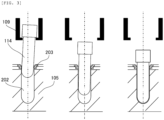
- Patent Literature 1 no consideration is paid to the insertion of a reaction vessel, specifically a reaction vessel in a tubular shape into a hole of the incubator.
- the reaction vessel in a tubular shape can reduce the liquid amount of a sample of the reaction vessel in a tapered shape, the resistance at the time of insertion into the hole of the incubator.
- the increase in resistance at the time of insertion sometimes makes the mounting of the reaction vessel into the incubator, and the processing performance of the automatic analyzer is sometimes reduced.
- the present invention is an automatic analyzer as defined in appended claim 1.
- an automatic analyzer that is capable of smoothly inserting a reaction vessel into the hole of the incubator.
- ⁇ is a proportionality constant determined for every type of specific component. That is, the concentration C of the specific component is calculated from the value of the absorbance A ⁇ calculated from the intensity I ⁇ of the transmitted light beam of the reaction solution and the optical path length L.
- the incubator 105 in Fig. 2 has a board 201 in a ring shape that rotates at a predetermined angle every lapse of a predetermined time period at a central axis 200 as a rotation axis, a heater 204, and an insulation 205.
- the components will be described.
- the radial direction of the board 201 is defined as an R axis
- the circumferential direction is defined as a ⁇ axis
- the vertical direction that is a direction in parallel with the central axis 200 is defined as a Z-axis.
- the heater 204 is a hating resistor in a belt shape that is disposed so as to cover the side surface of the outer periphery of the board 201, and the supply of electric power is controlled based on the measured value of a thermometer, not shown, provided on the board 201.
- the insulation 205 is a material having a relatively low coefficient of thermal conductivity, and the insulation 205 is disposed so as to cover the outer periphery of the heater 204 and the bottom surface of the board 201.
- the board 201 is kept at a predetermined temperature by the heating of the heater 204 and the insulation of the insulation 205, the reaction of the mixed solution in the reaction vessel 114 inserted into the hole 202 progresses, and the reaction solution is generated.
- a photometric hole 206 is provided, and is used for measuring the absorbance of the reaction solution of the spectrophotometer 115.
- the photometric hole 206 may be provided for every hole 202 to be inserted into the reaction vessel 114, or may be provided at every several holes 202, for example, at every one hole 202.
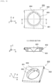
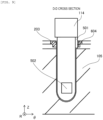
- Fig. 5 shows a side view of the reaction vessel 114 seen from the R direction and a B-B cross sectional view of the side view.
- the reaction vessel 114 in Fig. 5 has a protrusion 501 and two translucent surfaces 502, and places other than the places at which the protrusion 501 and the translucent surface 502 are provided are in a tubular shape. That is, most of the reaction vessel 114 is in a tubular shape.
- the protrusion 501 is a portion protruding from the side surface of the reaction vessel 114, and is provided so as to have a predetermined angle to the translucent surface 502 about the central axis of the reaction vessel 114 in parallel with each other the Z-axis.
- the angle of the protrusion 501 to the translucent surface 502 is 0° such that the protrusion 501 is in parallel with each other the translucent surface 502.
- the claw 602 is a portion that engages with the incubator 105 in order to prevent the lubricating member 203 having self lubricity from falling off from the incubator 105. That is, since there is the case in which the lubricating member 203 that is slippery to the incubator 105 falls off even though the reaction vessel 114 slightly touches the lubricating member 203, the incubator 105 engages with the claw 602, and thus the lubricating member 203 is prevented from falling off.
- the chamfering portion 603 is an inclined plane provided on the edge of the opening of the lubricating member 203 whose side of the hole 202 is low, in order to mitigate the resistance when the reaction vessel 114 is inserted into the lubricating member 203. Note that since the coefficient of friction of the lubricating member 203 having self lubricity is extremely small, the chamfering portion 603 does not necessarily have to be provided.
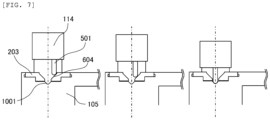
- the guide groove 604 as an example of the directional portion is a groove having a function of facing the translucent surface 502 to the photometric hole 206, into which the protrusion 501 is fit. That is, in the case in which the angle of the protrusion 501 to the translucent surface 502 is 0°, the guide groove 604 is provided along the circumferential direction of the incubator 105.
- the guide groove 604 has a Y-groove shape. Even though the protrusion 501 is displaced more or less to the guide groove 604, the displacement is corrected along the Y-groove as shown in Fig. 7 , and the positioning accuracy of the reaction vessel 114 is reserved.
- the directional portion is not limited to the guide groove 604.
- the site corresponding to the guide groove 604 may be formed in a projecting shape, and the site corresponding to the protrusion 501 may be formed in a recessed shape.
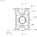
- the incubator 105 in Fig. 10 has an inter-hole groove 1001 along the circumferential direction between the adjacent holes 202.
- the inter-hole groove 1001 is provided in parallel with the guide groove 604 of the lubricating member 203, and into which the protrusion 501 of the reaction vessel 114 is fit.
- the reaction vessel 114 is smoothly inserted into the hole 202.
- Such smooth insertion surely mounts the reaction vessel 114 on the incubator 105, and thus it is possible to maintain the processing performance of the automatic analyzer 100.
- the automatic analyzer 100 for biochemical testing has been described.
- an automatic analyzer 100 for immunologic testing using antigen antibody reactions shown in Fig. 11 will be described. Note that differences from the first embodiment are in that configurations involved in analysis and a pre-wash unit 108 and an analysis unit 110 are provided instead of the spectrophotometer 115.
- the analysis unit 110 analyzes the reaction solution from which unnecessary components contained in the transferred reaction vessel 114 is separated.
- the analysis unit 110 has a light source, a spectral element, and a photodetector, and has a function that adjusts temperatures in order to maintain the reproducibility of analysis.
- the reaction vessel 114 containing the reaction solution to be analyzed is transferred from the incubator 105 to the analysis unit 110, and then analyzed by the analysis unit 110.
- the incubator 105 of the present embodiment since a lubricating member 203 having self lubricity is provided at the inlet port of a hole 202, the reaction vessel 114 is smoothly inserted into the hole 202.
- the incubator 105 of the present embodiment may include or not include a photometric hole 206.
- two protrusions 501 may be provided.
- the two guide grooves 604 and the two protrusions 501 may be provided at opposite positions, or may be provided with a given angle difference.
- the first protrusion and the second protrusion may have different shapes.
- one protrusion 501 may be provided, and the numbers of the guide grooves 604 and the protrusions 501 do not necessarily have to be the same.
- the number of the guide grooves 604 is not limited in the range in which the guide grooves 604 can be provided at the hole 202, as long as the numbers of the guide grooves 604 is equal to or more than the number of the protrusions 501.
Landscapes
- Chemical & Material Sciences (AREA)
- General Health & Medical Sciences (AREA)
- Life Sciences & Earth Sciences (AREA)
- Health & Medical Sciences (AREA)
- Analytical Chemistry (AREA)
- Biochemistry (AREA)
- Physics & Mathematics (AREA)
- General Physics & Mathematics (AREA)
- Immunology (AREA)
- Pathology (AREA)
- Chemical Kinetics & Catalysis (AREA)
- Engineering & Computer Science (AREA)
- Robotics (AREA)
- Automatic Analysis And Handling Materials Therefor (AREA)
Claims (5)
- Automatisches Analysegerät (100), umfassend:ein Reaktionsgefäß (114), das eine Mischung aus einer Probe und einem Reagens enthält;einen Inkubator (105) mit einer Öffnung, in die das Reaktionsgefäß (114) eingesetzt werden soll;eine Überführungseinheit (109), die dazu konfiguriert ist, ein unbenutztes Reaktionsgefäß (114) in den Inkubator (105) zu überführen und das Reaktionsgefäß (114) in die Öffnung einzusetzen; undein Schmierelement (203) mit einer selbstschmierenden Eigenschaft, das an einem Einlass der Öffnung vorgesehen ist,dadurch gekennzeichnet, dassdas Reaktionsgefäß (114) eine durchscheinende Oberfläche (502) hat, die eine ebene Fläche ist, durch die Licht zur Analyse durchgelassen werden soll,das Schmierelement (203) einen Ausrichtungsabschnitt aufweist, der die durchscheinende Oberfläche (502) in eine vorbestimmte Richtung lenkt,das Reaktionsgefäß (114) ferner einen Vorsprung (501) aufweist, der von einer Seitenfläche vorsteht, undder Ausrichtungsabschnitt eine Führungsnut (604) aufweist, die eine Nut ist, die zu dem Vorsprung (501) passt und die eine Y-Nutform aufweist, entlang der eine relative Verschiebung des Vorsprungs (501) zu der Führungsnut (604) korrigiert wird.
- Automatisches Analysegerät (100) nach Anspruch 1, wobei der Inkubator (105) eine Nut (1001) parallel zu der Führungsnut (604) aufweist.
- Automatisches Analysegerät (100) nach Anspruch 1, wobei das Material des Schmierelements (203) eines der folgenden ist: PTFE, Polyacetal, Polyethylen mit ultrahohem Molekulargewicht oder monomeres Gussnylon.
- Automatisches Analysegerät (100) nach Anspruch 1, wobei das Schmierelement (203) eine Klaue (602) aufweist, die in den Inkubator (105) eingreift.
- Automatisches Analysegerät (100) nach Anspruch 1, wobei das Schmierelement (203) einen abgeschrägten Abschnitt (603) aufweist, der eine geneigte Oberfläche ist, die zu der Öffnung hin niedriger ist.
Applications Claiming Priority (2)
| Application Number | Priority Date | Filing Date | Title |
|---|---|---|---|
| JP2020083219 | 2020-05-11 | ||
| PCT/JP2021/004449 WO2021229874A1 (ja) | 2020-05-11 | 2021-02-05 | 自動分析装置および反応容器の挿入方法 |
Publications (3)
| Publication Number | Publication Date |
|---|---|
| EP4152006A1 EP4152006A1 (de) | 2023-03-22 |
| EP4152006A4 EP4152006A4 (de) | 2024-05-22 |
| EP4152006B1 true EP4152006B1 (de) | 2025-07-09 |
Family
ID=78525779
Family Applications (1)
| Application Number | Title | Priority Date | Filing Date |
|---|---|---|---|
| EP21802189.7A Active EP4152006B1 (de) | 2020-05-11 | 2021-02-05 | Automatische analysevorrichtung |
Country Status (5)
| Country | Link |
|---|---|
| US (1) | US12566189B2 (de) |
| EP (1) | EP4152006B1 (de) |
| JP (1) | JP7379692B2 (de) |
| CN (1) | CN115461625B (de) |
| WO (1) | WO2021229874A1 (de) |
Family Cites Families (28)
| Publication number | Priority date | Publication date | Assignee | Title |
|---|---|---|---|---|
| US4310488A (en) * | 1980-05-19 | 1982-01-12 | Hoffmann-La Roche Inc. | Sample or reagent container for analyzers |
| JPH05142234A (ja) | 1991-11-15 | 1993-06-08 | Olympus Optical Co Ltd | 自動分析装置用反応容器ホルダー |
| DE69308493T2 (de) * | 1992-06-29 | 1997-10-23 | Dade Int Inc | Träger für proberöhrchen |
| US5976896A (en) * | 1994-06-06 | 1999-11-02 | Idexx Laboratories, Inc. | Immunoassays in capillary tubes |
| US5599501A (en) * | 1994-11-10 | 1997-02-04 | Ciba Corning Diagnostics Corp. | Incubation chamber |
| HRP970061B1 (en) * | 1996-02-02 | 1999-12-31 | Donald M. Davies | Agglutination reaction and separation vessel |
| US5632399A (en) * | 1996-06-28 | 1997-05-27 | Dpc Cirrus Inc. | Self-sealing reagent container and reagent container system |
| US8337753B2 (en) * | 1998-05-01 | 2012-12-25 | Gen-Probe Incorporated | Temperature-controlled incubator having a receptacle mixing mechanism |
| JP2003107096A (ja) * | 2001-09-28 | 2003-04-09 | Hitachi Ltd | 自動分析装置 |
| US20030111494A1 (en) * | 2001-10-26 | 2003-06-19 | Sequenom, Inc. | Method and apparatus for high-throughput sample handling process line |
| GB0322444D0 (en) * | 2003-09-25 | 2003-10-29 | Rts Thurnall Plc | Actuator assembly |
| JP4564822B2 (ja) * | 2004-10-27 | 2010-10-20 | 株式会社日立ハイテクノロジーズ | 反応容器及びそれを用いた自動分析装置 |
| US7776263B2 (en) * | 2004-10-29 | 2010-08-17 | Abbott Laboratories Inc. | Apparatus for providing homogeneous dispersions |
| CA2588820A1 (en) | 2004-11-30 | 2006-06-08 | Global Technologies (Nz) Ltd | Method of sample analysis and apparatus therefor |
| JP2006292696A (ja) * | 2005-04-15 | 2006-10-26 | Hitachi High-Technologies Corp | 検体ラック、及び検体ラック用アダプタ |
| JP2008241500A (ja) * | 2007-03-28 | 2008-10-09 | Fujifilm Corp | マイクロチップの位置決め部材 |
| US8486346B2 (en) * | 2008-05-19 | 2013-07-16 | Abbott Laboratories | Gas scrubber for automated clinical analyzer |
| GB201005885D0 (en) * | 2010-04-08 | 2010-05-26 | Avacta Ltd | Apparatus and method |
| US9046507B2 (en) * | 2010-07-29 | 2015-06-02 | Gen-Probe Incorporated | Method, system and apparatus for incorporating capacitive proximity sensing in an automated fluid transfer procedure |
| CN202304645U (zh) * | 2011-11-07 | 2012-07-04 | 攀钢集团工程技术有限公司 | 用于装药台车输药管的管帽 |
| JP6033959B2 (ja) | 2013-01-09 | 2016-11-30 | テカン・トレーディング・アクチェンゲゼルシャフトTECAN Trading AG | マイクロ流体システム用使い捨てカートリッジ |
| JP6348816B2 (ja) * | 2014-09-30 | 2018-06-27 | 株式会社日立ハイテクノロジーズ | 自動分析装置 |
| EP3314269A4 (de) | 2015-06-26 | 2019-01-23 | Abbott Laboratories | Reaktionsgefässtauschervorrichtung für einen diagnostischen analysator |
| JP6659877B2 (ja) | 2017-02-07 | 2020-03-04 | 株式会社日立ハイテクノロジーズ | 自動分析装置 |
| JP6948158B2 (ja) * | 2017-05-29 | 2021-10-13 | シスメックス株式会社 | 試料処理装置及び試料処理方法 |
| EP3710845B1 (de) * | 2017-11-17 | 2021-08-11 | Numares AG | Nmr-anordnung und verfahren zum transport eines probenröhrchens in einer nmr-anordnung |
| CN111712452B (zh) | 2018-02-23 | 2022-06-14 | 美国西门子医学诊断股份有限公司 | 临床分析仪和用于运输样品池的方法 |
| JP7163400B2 (ja) * | 2018-09-27 | 2022-10-31 | 株式会社日立ハイテク | 自動分析装置用反応容器 |
-
2021
- 2021-02-05 CN CN202180028233.0A patent/CN115461625B/zh active Active
- 2021-02-05 WO PCT/JP2021/004449 patent/WO2021229874A1/ja not_active Ceased
- 2021-02-05 US US17/923,685 patent/US12566189B2/en active Active
- 2021-02-05 JP JP2022522519A patent/JP7379692B2/ja active Active
- 2021-02-05 EP EP21802189.7A patent/EP4152006B1/de active Active
Also Published As
| Publication number | Publication date |
|---|---|
| EP4152006A1 (de) | 2023-03-22 |
| EP4152006A4 (de) | 2024-05-22 |
| WO2021229874A1 (ja) | 2021-11-18 |
| CN115461625B (zh) | 2025-10-28 |
| JP7379692B2 (ja) | 2023-11-14 |
| US12566189B2 (en) | 2026-03-03 |
| JPWO2021229874A1 (de) | 2021-11-18 |
| US20230184797A1 (en) | 2023-06-15 |
| CN115461625A (zh) | 2022-12-09 |
Similar Documents
| Publication | Publication Date | Title |
|---|---|---|
| US5986754A (en) | Medical diagnostic apparatus using a Fresnel reflector | |
| EP2466291B1 (de) | Küvette zur fotometrischen Messung kleiner Flüssigkeitsmengen | |
| US4406547A (en) | Apparatus for effecting automatic analysis | |
| JP6813953B2 (ja) | 血液凝固分析装置および血液凝固分析方法 | |
| US8064061B2 (en) | Sample analyzer and sample analyzing method | |
| EP2605020B1 (de) | Verfahren zur Probenanalyse und Probenanalysator | |
| EP2466292B1 (de) | System zur Durchführung von Streuungs- und Absorptionsassays | |
| JP2006526778A (ja) | 光学検査装置のための読み取りヘッド | |
| US11668647B2 (en) | Illumination unit with multiple light sources for generating a uniform illumination spot | |
| EP2607883A1 (de) | System zur photometrischen Messung von Flüssigkeiten | |
| EP4152006B1 (de) | Automatische analysevorrichtung | |
| JP2024028855A (ja) | 血液凝固分析装置および血液凝固分析方法 | |
| Schultz et al. | Two-dimensional centrifugation for desk-top clinical chemistry. | |
| EP0864867B1 (de) | Verbesserung des Analysator-Durchsatzes mittels einer Analyse an der Pipettenspitze | |
| EP0110262A2 (de) | Optischer Lesekopf | |
| JP7546141B2 (ja) | 光源及び自動分析装置 | |
| US7277167B2 (en) | Modular cuvettes and methods for use thereof | |
| JP7649856B2 (ja) | 自動分析装置、及び反応容器 | |
| JP4838086B2 (ja) | 化学発光測定装置 | |
| JP2000039395A (ja) | 臨床分析装置においてスループットを改善する方法 | |
| WO2025115320A1 (ja) | 発光分析用検出装置及び自動分析装置 | |
| JPS6111631A (ja) | 化学分析スライド収納カ−トリツジの停止位置検出装置 | |
| JP2001074553A (ja) | 生化学分析装置 | |
| CN117396748A (zh) | 测光装置和分析装置 | |
| Bais et al. | Assessment of the Cobas Bio centrifugal analyser |
Legal Events
| Date | Code | Title | Description |
|---|---|---|---|
| STAA | Information on the status of an ep patent application or granted ep patent |
Free format text: STATUS: THE INTERNATIONAL PUBLICATION HAS BEEN MADE |
|
| PUAI | Public reference made under article 153(3) epc to a published international application that has entered the european phase |
Free format text: ORIGINAL CODE: 0009012 |
|
| STAA | Information on the status of an ep patent application or granted ep patent |
Free format text: STATUS: REQUEST FOR EXAMINATION WAS MADE |
|
| 17P | Request for examination filed |
Effective date: 20221020 |
|
| AK | Designated contracting states |
Kind code of ref document: A1 Designated state(s): AL AT BE BG CH CY CZ DE DK EE ES FI FR GB GR HR HU IE IS IT LI LT LU LV MC MK MT NL NO PL PT RO RS SE SI SK SM TR |
|
| DAV | Request for validation of the european patent (deleted) | ||
| DAX | Request for extension of the european patent (deleted) | ||
| A4 | Supplementary search report drawn up and despatched |
Effective date: 20240419 |
|
| RIC1 | Information provided on ipc code assigned before grant |
Ipc: G01N 35/04 20060101ALI20240415BHEP Ipc: G01N 35/02 20060101AFI20240415BHEP |
|
| GRAP | Despatch of communication of intention to grant a patent |
Free format text: ORIGINAL CODE: EPIDOSNIGR1 |
|
| STAA | Information on the status of an ep patent application or granted ep patent |
Free format text: STATUS: GRANT OF PATENT IS INTENDED |
|
| INTG | Intention to grant announced |
Effective date: 20250320 |
|
| GRAS | Grant fee paid |
Free format text: ORIGINAL CODE: EPIDOSNIGR3 |
|
| GRAA | (expected) grant |
Free format text: ORIGINAL CODE: 0009210 |
|
| STAA | Information on the status of an ep patent application or granted ep patent |
Free format text: STATUS: THE PATENT HAS BEEN GRANTED |
|
| AK | Designated contracting states |
Kind code of ref document: B1 Designated state(s): AL AT BE BG CH CY CZ DE DK EE ES FI FR GB GR HR HU IE IS IT LI LT LU LV MC MK MT NL NO PL PT RO RS SE SI SK SM TR |
|
| REG | Reference to a national code |
Ref country code: GB Ref legal event code: FG4D |
|
| REG | Reference to a national code |
Ref country code: CH Ref legal event code: EP |
|
| REG | Reference to a national code |
Ref country code: IE Ref legal event code: FG4D |
|
| REG | Reference to a national code |
Ref country code: DE Ref legal event code: R096 Ref document number: 602021033889 Country of ref document: DE |
|
| REG | Reference to a national code |
Ref country code: NL Ref legal event code: MP Effective date: 20250709 |
|
| PG25 | Lapsed in a contracting state [announced via postgrant information from national office to epo] |
Ref country code: PT Free format text: LAPSE BECAUSE OF FAILURE TO SUBMIT A TRANSLATION OF THE DESCRIPTION OR TO PAY THE FEE WITHIN THE PRESCRIBED TIME-LIMIT Effective date: 20251110 |
|
| PG25 | Lapsed in a contracting state [announced via postgrant information from national office to epo] |
Ref country code: NL Free format text: LAPSE BECAUSE OF FAILURE TO SUBMIT A TRANSLATION OF THE DESCRIPTION OR TO PAY THE FEE WITHIN THE PRESCRIBED TIME-LIMIT Effective date: 20250709 |
|
| REG | Reference to a national code |
Ref country code: AT Ref legal event code: MK05 Ref document number: 1812260 Country of ref document: AT Kind code of ref document: T Effective date: 20250709 |
|
| PG25 | Lapsed in a contracting state [announced via postgrant information from national office to epo] |
Ref country code: IS Free format text: LAPSE BECAUSE OF FAILURE TO SUBMIT A TRANSLATION OF THE DESCRIPTION OR TO PAY THE FEE WITHIN THE PRESCRIBED TIME-LIMIT Effective date: 20251109 |
|
| PG25 | Lapsed in a contracting state [announced via postgrant information from national office to epo] |
Ref country code: NO Free format text: LAPSE BECAUSE OF FAILURE TO SUBMIT A TRANSLATION OF THE DESCRIPTION OR TO PAY THE FEE WITHIN THE PRESCRIBED TIME-LIMIT Effective date: 20251009 |
|
| REG | Reference to a national code |
Ref country code: LT Ref legal event code: MG9D |
|
| PG25 | Lapsed in a contracting state [announced via postgrant information from national office to epo] |
Ref country code: AT Free format text: LAPSE BECAUSE OF FAILURE TO SUBMIT A TRANSLATION OF THE DESCRIPTION OR TO PAY THE FEE WITHIN THE PRESCRIBED TIME-LIMIT Effective date: 20250709 |
|
| PG25 | Lapsed in a contracting state [announced via postgrant information from national office to epo] |
Ref country code: FI Free format text: LAPSE BECAUSE OF FAILURE TO SUBMIT A TRANSLATION OF THE DESCRIPTION OR TO PAY THE FEE WITHIN THE PRESCRIBED TIME-LIMIT Effective date: 20250709 |
|
| PG25 | Lapsed in a contracting state [announced via postgrant information from national office to epo] |
Ref country code: HR Free format text: LAPSE BECAUSE OF FAILURE TO SUBMIT A TRANSLATION OF THE DESCRIPTION OR TO PAY THE FEE WITHIN THE PRESCRIBED TIME-LIMIT Effective date: 20250709 |
|
| PG25 | Lapsed in a contracting state [announced via postgrant information from national office to epo] |
Ref country code: GR Free format text: LAPSE BECAUSE OF FAILURE TO SUBMIT A TRANSLATION OF THE DESCRIPTION OR TO PAY THE FEE WITHIN THE PRESCRIBED TIME-LIMIT Effective date: 20251010 |
|
| PG25 | Lapsed in a contracting state [announced via postgrant information from national office to epo] |
Ref country code: SE Free format text: LAPSE BECAUSE OF FAILURE TO SUBMIT A TRANSLATION OF THE DESCRIPTION OR TO PAY THE FEE WITHIN THE PRESCRIBED TIME-LIMIT Effective date: 20250709 |
|
| PG25 | Lapsed in a contracting state [announced via postgrant information from national office to epo] |
Ref country code: LV Free format text: LAPSE BECAUSE OF FAILURE TO SUBMIT A TRANSLATION OF THE DESCRIPTION OR TO PAY THE FEE WITHIN THE PRESCRIBED TIME-LIMIT Effective date: 20250709 |
|
| PG25 | Lapsed in a contracting state [announced via postgrant information from national office to epo] |
Ref country code: BG Free format text: LAPSE BECAUSE OF FAILURE TO SUBMIT A TRANSLATION OF THE DESCRIPTION OR TO PAY THE FEE WITHIN THE PRESCRIBED TIME-LIMIT Effective date: 20250709 Ref country code: PL Free format text: LAPSE BECAUSE OF FAILURE TO SUBMIT A TRANSLATION OF THE DESCRIPTION OR TO PAY THE FEE WITHIN THE PRESCRIBED TIME-LIMIT Effective date: 20250709 |
|
| PG25 | Lapsed in a contracting state [announced via postgrant information from national office to epo] |
Ref country code: RS Free format text: LAPSE BECAUSE OF FAILURE TO SUBMIT A TRANSLATION OF THE DESCRIPTION OR TO PAY THE FEE WITHIN THE PRESCRIBED TIME-LIMIT Effective date: 20251009 |
|
| PG25 | Lapsed in a contracting state [announced via postgrant information from national office to epo] |
Ref country code: ES Free format text: LAPSE BECAUSE OF FAILURE TO SUBMIT A TRANSLATION OF THE DESCRIPTION OR TO PAY THE FEE WITHIN THE PRESCRIBED TIME-LIMIT Effective date: 20250709 |
|
| PG25 | Lapsed in a contracting state [announced via postgrant information from national office to epo] |
Ref country code: SM Free format text: LAPSE BECAUSE OF FAILURE TO SUBMIT A TRANSLATION OF THE DESCRIPTION OR TO PAY THE FEE WITHIN THE PRESCRIBED TIME-LIMIT Effective date: 20250709 |
|
| PG25 | Lapsed in a contracting state [announced via postgrant information from national office to epo] |
Ref country code: DK Free format text: LAPSE BECAUSE OF FAILURE TO SUBMIT A TRANSLATION OF THE DESCRIPTION OR TO PAY THE FEE WITHIN THE PRESCRIBED TIME-LIMIT Effective date: 20250709 |
|
| PGFP | Annual fee paid to national office [announced via postgrant information from national office to epo] |
Ref country code: DE Payment date: 20260223 Year of fee payment: 6 |
|
| PG25 | Lapsed in a contracting state [announced via postgrant information from national office to epo] |
Ref country code: IT Free format text: LAPSE BECAUSE OF FAILURE TO SUBMIT A TRANSLATION OF THE DESCRIPTION OR TO PAY THE FEE WITHIN THE PRESCRIBED TIME-LIMIT Effective date: 20250709 |
|
| PGFP | Annual fee paid to national office [announced via postgrant information from national office to epo] |
Ref country code: FR Payment date: 20260227 Year of fee payment: 6 |
|
| PG25 | Lapsed in a contracting state [announced via postgrant information from national office to epo] |
Ref country code: CZ Free format text: LAPSE BECAUSE OF FAILURE TO SUBMIT A TRANSLATION OF THE DESCRIPTION OR TO PAY THE FEE WITHIN THE PRESCRIBED TIME-LIMIT Effective date: 20250709 |
|
| PG25 | Lapsed in a contracting state [announced via postgrant information from national office to epo] |
Ref country code: EE Free format text: LAPSE BECAUSE OF FAILURE TO SUBMIT A TRANSLATION OF THE DESCRIPTION OR TO PAY THE FEE WITHIN THE PRESCRIBED TIME-LIMIT Effective date: 20250709 Ref country code: SK Free format text: LAPSE BECAUSE OF FAILURE TO SUBMIT A TRANSLATION OF THE DESCRIPTION OR TO PAY THE FEE WITHIN THE PRESCRIBED TIME-LIMIT Effective date: 20250709 |