EP4155149B1 - Steuerungsvorrichtung für fahrzeug - Google Patents
Steuerungsvorrichtung für fahrzeug Download PDFInfo
- Publication number
- EP4155149B1 EP4155149B1 EP22188868.8A EP22188868A EP4155149B1 EP 4155149 B1 EP4155149 B1 EP 4155149B1 EP 22188868 A EP22188868 A EP 22188868A EP 4155149 B1 EP4155149 B1 EP 4155149B1
- Authority
- EP
- European Patent Office
- Prior art keywords
- vehicle
- driving
- lane
- steering
- avoidance
- Prior art date
- Legal status (The legal status is an assumption and is not a legal conclusion. Google has not performed a legal analysis and makes no representation as to the accuracy of the status listed.)
- Active
Links
Images





Classifications
-
- B—PERFORMING OPERATIONS; TRANSPORTING
- B60—VEHICLES IN GENERAL
- B60W—CONJOINT CONTROL OF VEHICLE SUB-UNITS OF DIFFERENT TYPE OR DIFFERENT FUNCTION; CONTROL SYSTEMS SPECIALLY ADAPTED FOR HYBRID VEHICLES; ROAD VEHICLE DRIVE CONTROL SYSTEMS FOR PURPOSES NOT RELATED TO THE CONTROL OF A PARTICULAR SUB-UNIT
- B60W30/00—Purposes of road vehicle drive control systems not related to the control of a particular sub-unit, e.g. of systems using conjoint control of vehicle sub-units
- B60W30/10—Path keeping
- B60W30/12—Lane keeping
-
- B—PERFORMING OPERATIONS; TRANSPORTING
- B60—VEHICLES IN GENERAL
- B60W—CONJOINT CONTROL OF VEHICLE SUB-UNITS OF DIFFERENT TYPE OR DIFFERENT FUNCTION; CONTROL SYSTEMS SPECIALLY ADAPTED FOR HYBRID VEHICLES; ROAD VEHICLE DRIVE CONTROL SYSTEMS FOR PURPOSES NOT RELATED TO THE CONTROL OF A PARTICULAR SUB-UNIT
- B60W30/00—Purposes of road vehicle drive control systems not related to the control of a particular sub-unit, e.g. of systems using conjoint control of vehicle sub-units
- B60W30/08—Active safety systems predicting or avoiding probable or impending collision or attempting to minimise its consequences
- B60W30/09—Taking automatic action to avoid collision, e.g. braking and steering
-
- B—PERFORMING OPERATIONS; TRANSPORTING
- B60—VEHICLES IN GENERAL
- B60W—CONJOINT CONTROL OF VEHICLE SUB-UNITS OF DIFFERENT TYPE OR DIFFERENT FUNCTION; CONTROL SYSTEMS SPECIALLY ADAPTED FOR HYBRID VEHICLES; ROAD VEHICLE DRIVE CONTROL SYSTEMS FOR PURPOSES NOT RELATED TO THE CONTROL OF A PARTICULAR SUB-UNIT
- B60W30/00—Purposes of road vehicle drive control systems not related to the control of a particular sub-unit, e.g. of systems using conjoint control of vehicle sub-units
- B60W30/08—Active safety systems predicting or avoiding probable or impending collision or attempting to minimise its consequences
- B60W30/095—Predicting travel path or likelihood of collision
-
- B—PERFORMING OPERATIONS; TRANSPORTING
- B60—VEHICLES IN GENERAL
- B60W—CONJOINT CONTROL OF VEHICLE SUB-UNITS OF DIFFERENT TYPE OR DIFFERENT FUNCTION; CONTROL SYSTEMS SPECIALLY ADAPTED FOR HYBRID VEHICLES; ROAD VEHICLE DRIVE CONTROL SYSTEMS FOR PURPOSES NOT RELATED TO THE CONTROL OF A PARTICULAR SUB-UNIT
- B60W30/00—Purposes of road vehicle drive control systems not related to the control of a particular sub-unit, e.g. of systems using conjoint control of vehicle sub-units
- B60W30/08—Active safety systems predicting or avoiding probable or impending collision or attempting to minimise its consequences
- B60W30/095—Predicting travel path or likelihood of collision
- B60W30/0956—Predicting travel path or likelihood of collision the prediction being responsive to traffic or environmental parameters
-
- B—PERFORMING OPERATIONS; TRANSPORTING
- B60—VEHICLES IN GENERAL
- B60W—CONJOINT CONTROL OF VEHICLE SUB-UNITS OF DIFFERENT TYPE OR DIFFERENT FUNCTION; CONTROL SYSTEMS SPECIALLY ADAPTED FOR HYBRID VEHICLES; ROAD VEHICLE DRIVE CONTROL SYSTEMS FOR PURPOSES NOT RELATED TO THE CONTROL OF A PARTICULAR SUB-UNIT
- B60W30/00—Purposes of road vehicle drive control systems not related to the control of a particular sub-unit, e.g. of systems using conjoint control of vehicle sub-units
- B60W30/14—Adaptive cruise control
- B60W30/143—Speed control
-
- B—PERFORMING OPERATIONS; TRANSPORTING
- B60—VEHICLES IN GENERAL
- B60W—CONJOINT CONTROL OF VEHICLE SUB-UNITS OF DIFFERENT TYPE OR DIFFERENT FUNCTION; CONTROL SYSTEMS SPECIALLY ADAPTED FOR HYBRID VEHICLES; ROAD VEHICLE DRIVE CONTROL SYSTEMS FOR PURPOSES NOT RELATED TO THE CONTROL OF A PARTICULAR SUB-UNIT
- B60W30/00—Purposes of road vehicle drive control systems not related to the control of a particular sub-unit, e.g. of systems using conjoint control of vehicle sub-units
- B60W30/14—Adaptive cruise control
- B60W30/16—Control of distance between vehicles, e.g. keeping a distance to preceding vehicle
-
- B—PERFORMING OPERATIONS; TRANSPORTING
- B60—VEHICLES IN GENERAL
- B60W—CONJOINT CONTROL OF VEHICLE SUB-UNITS OF DIFFERENT TYPE OR DIFFERENT FUNCTION; CONTROL SYSTEMS SPECIALLY ADAPTED FOR HYBRID VEHICLES; ROAD VEHICLE DRIVE CONTROL SYSTEMS FOR PURPOSES NOT RELATED TO THE CONTROL OF A PARTICULAR SUB-UNIT
- B60W2520/00—Input parameters relating to overall vehicle dynamics
- B60W2520/06—Direction of travel
-
- B—PERFORMING OPERATIONS; TRANSPORTING
- B60—VEHICLES IN GENERAL
- B60W—CONJOINT CONTROL OF VEHICLE SUB-UNITS OF DIFFERENT TYPE OR DIFFERENT FUNCTION; CONTROL SYSTEMS SPECIALLY ADAPTED FOR HYBRID VEHICLES; ROAD VEHICLE DRIVE CONTROL SYSTEMS FOR PURPOSES NOT RELATED TO THE CONTROL OF A PARTICULAR SUB-UNIT
- B60W2552/00—Input parameters relating to infrastructure
- B60W2552/10—Number of lanes
-
- B—PERFORMING OPERATIONS; TRANSPORTING
- B60—VEHICLES IN GENERAL
- B60W—CONJOINT CONTROL OF VEHICLE SUB-UNITS OF DIFFERENT TYPE OR DIFFERENT FUNCTION; CONTROL SYSTEMS SPECIALLY ADAPTED FOR HYBRID VEHICLES; ROAD VEHICLE DRIVE CONTROL SYSTEMS FOR PURPOSES NOT RELATED TO THE CONTROL OF A PARTICULAR SUB-UNIT
- B60W2552/00—Input parameters relating to infrastructure
- B60W2552/50—Barriers
-
- B—PERFORMING OPERATIONS; TRANSPORTING
- B60—VEHICLES IN GENERAL
- B60W—CONJOINT CONTROL OF VEHICLE SUB-UNITS OF DIFFERENT TYPE OR DIFFERENT FUNCTION; CONTROL SYSTEMS SPECIALLY ADAPTED FOR HYBRID VEHICLES; ROAD VEHICLE DRIVE CONTROL SYSTEMS FOR PURPOSES NOT RELATED TO THE CONTROL OF A PARTICULAR SUB-UNIT
- B60W2552/00—Input parameters relating to infrastructure
- B60W2552/53—Road markings, e.g. lane marker or crosswalk
-
- B—PERFORMING OPERATIONS; TRANSPORTING
- B60—VEHICLES IN GENERAL
- B60W—CONJOINT CONTROL OF VEHICLE SUB-UNITS OF DIFFERENT TYPE OR DIFFERENT FUNCTION; CONTROL SYSTEMS SPECIALLY ADAPTED FOR HYBRID VEHICLES; ROAD VEHICLE DRIVE CONTROL SYSTEMS FOR PURPOSES NOT RELATED TO THE CONTROL OF A PARTICULAR SUB-UNIT
- B60W2554/00—Input parameters relating to objects
- B60W2554/80—Spatial relation or speed relative to objects
- B60W2554/801—Lateral distance
Definitions
- the present invention relates to driving control apparatuses for vehicles, and more particularly, relates to an emergency avoidance function during operation of an automatic lane keeping system.
- driving control systems are being put into practical use and are being internationally standardized for purposes of reducing burdens on drivers and for supporting safe driving.
- driving control systems such as an inter-vehicle distance control system (ACCS) and a lane keeping assistance system (LKAS) that have already been put into practical use, and a “partially automated in-lane driving system (PADS)” that is a combination of these, are in the process of being put into practical use.
- AKS automated lane keeping system
- AKS automated lane keeping system
- Patent Document 1 discloses increasing a lateral distance from another vehicle traveling in parallel when an automatic stop mode that stops a vehicle in a predetermined stop area is performed in a case in which a predetermined condition that makes it difficult for a vehicle control system or driver to continue driving is satisfied while the vehicle is traveling.
- Patent Documents 2-5 Other examples of background art can be found in Patent Documents 2-5.
- a vehicle 1 equipped with a driving control system includes, in addition to common components, such as an engine and a vehicle body, of an automobile, an external sensor 21 for detecting a vehicle surrounding environment, an internal sensor 22 for detecting vehicle information, a controller/actuator group for speed control and steering control, an ACC controller 14 for inter-vehicle distance control, an LKA controller 15 for lane keeping control, and an automated driving controller 10 for controlling them to execute partially automated in-lane driving (PADS: Partially Automated in-lane Driving System), automated in-single lane driving (ALKS: Automatic Lane Keeping System), and automated lane change (PALS: Partially Automated Lane change System) in order to perform, at the vehicle side, recognition, determination, and operation conventionally performed by a driver.
- PADS Partially Automated in-lane Driving System
- ALKS Automatic Lane Keeping System
- PALS Partially Automated Lane change System
- the internal sensor 22 is composed of a plurality of detection means, such as a vehicle speed sensor, a yaw rate sensor and an acceleration sensor, for measuring physical quantities representing the vehicle's moving state, and their measurement values are input into the automated driving controller 10, ACC controller 14, LKA controller 15, and EPS controller 31 as shown in Figure 3 , and arithmetically processed together with the input from the external sensor 21.
- detection means such as a vehicle speed sensor, a yaw rate sensor and an acceleration sensor, for measuring physical quantities representing the vehicle's moving state, and their measurement values are input into the automated driving controller 10, ACC controller 14, LKA controller 15, and EPS controller 31 as shown in Figure 3 , and arithmetically processed together with the input from the external sensor 21.
- the vehicle speed is also input into the EPS controller 31 and ACC controller 14. Because a steering reaction force changes according to the vehicle speed, the EPS controller 31 refers to a steering angle-steering torque map for each vehicle speed and transmits a torque command to a steering mechanism 41.
- the engine controller 32, ESP/ABS controller 33, and EPS controller 31 control an engine 42, a brake 43, and the steering mechanism 41, and thereby the movement of the vehicle 1 in a longitudinal direction and a lateral direction is controlled.
- PADS partially automated in-lane driving system
- the environmental condition estimating part 11 constantly monitors whether the driving state and surrounding environmental condition of the vehicle and the driver's state are maintained within an operational design domain (ODD) on the basis of the external information obtained through the external sensor 21, the vehicle information obtained by the internal sensor 22, the driver's state obtained by the driver status monitor 25, and the like.
- ODD operational design domain
- the minimal risk maneuver refers to a function for automatic shifting to a minimal risk condition when the driver cannot take over the operation, although a change in the external driving environment or a failure or the like in the system has occurred and the driver is notified of the operation takeover request (TD), and specifically, includes control (safe stop) of decelerating and stopping in the lane by the automated driving controller 10.
- AKS automatic lane keeping system
- the automatic lane keeping system is a system combining the inter-vehicle distance control system (ACCS) and the lane keeping assistance system (LKAS) in the same way as the partially automated in-lane driving system (PADS), and is executed in a state in which both ACC controller 14 included in the inter-vehicle distance control system (ACCS) and the LKA controller 15 included in the lane keeping assistance system (LKAS) are operating together with the automated driving controller 10, but can only be executed in a speed range of 60 km/h or less.
- the automatic lane keeping system (ALKS) can be executed when the driver status monitor 25 confirms that the driver has responded to the takeover request and can take over driving; as long as the driver is seated in the driver's seat and the seatbelt is fastened, the driver is not required to monitor the driving situation.
- shift from the partially automated in-lane driving (PADS driving) to the automatic lane keeping system (ALKS) is performed when the vehicle speed falls to 50 km/h or less due to congestion on the highway substantially in a state of following cruise to the vehicle ahead by partially automated in-lane driving (PADS driving) or when, e.g., the vehicle catches up to the vehicle ahead that is driving at 50 km/h or less due to congestion.
- Figure 4 shows state transition of control in the automatic lane keeping system (ALKS).
- AKS automatic lane keeping system
- the environmental condition estimating part 11 constantly monitors the driving state and surrounding environmental condition of the vehicle, and the driver's state; when the environmental condition estimating part 11 determines that a system activation condition is not met, or detects a system failure (excluding serious failures described later), the system notifies the driver of the operation takeover request (TD) (120), and shifts from the automated lane keeping driving to the manual driving (140) when the driver takes over the driving operation within the predetermined time (for example, ten seconds).
- TD operation takeover request
- the minimal risk maneuver (MRM) When the driving operation takeover is not performed within the predetermined time, the minimal risk maneuver (MRM) is activated, and the risk minimization control (130) is performed.
- the environmental condition estimating part 11 determines that a serious failure has occurred in the system (such as engine hydraulic pressure reduction, engine water temperature increase, or brake system abnormality that may cause an accident, fire, or the like) during the operation of the automatic lane keeping system (ALKS)
- the operation takeover request (TD) is not made, the minimal risk maneuver (MRM) is immediately activated, and the risk minimization control (130) is performed.
- AKS automatic lane keeping system
- the automated driving system as described above enables override by the driver's operation intervention not only during the operation of the automatic lane keeping system (ALKS), but also during the operation of the risk minimization control (MRM) or emergency avoidance control (EM). That is, when the override (accelerator OR or brake OR) by the driver's acceleration/deceleration operation intervention or the override (steering OR) by the driver's steering intervention is performed, each automated driving function described above is stopped and the operation shifts to the driver's manual driving.
- ALKS automatic lane keeping system
- MRM risk minimization control
- EM emergency avoidance control
- the automatic emergency braking is performed when the emergency avoidance control (EM) is activated, but a braking distance may be insufficient depending on an activation situation, a road surface condition, or the like. Even in such a case, collision damage is expected to be reduced, but a collision avoidance probability can be increased by performing the avoidance steering in consideration of driving positions (lateral positions) of a vehicle ahead (cause vehicle) and a vehicle in the rear in the lane.
- the automated driving controller 10 constantly monitors the driving positions of the vehicle ahead (cause vehicle) and the vehicle in the rear as follows, in order to perform the avoidance steering at the same time as the automatic emergency braking (AEB) when the emergency avoidance control (EM) is activated.
- AEB automatic emergency braking
- EM emergency avoidance control
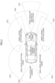
- the environmental condition estimating part 11 constantly detects a lateral position y2 ( Figure 6 ) within the lane of a vehicle ahead 2, together with the lane markings and the vehicle's own position, on the basis of the image data obtained by the external sensor 21 (cameras 212 and 215), and when there is a vehicle 4 in the rear within a rear predetermined distance in the vehicle's driving lane, further constantly detects its lateral position y4 ( Figure 7 ).
- the lateral position y2 of the vehicle ahead 2 is detected as a lateral deviation amount (relative deviation amount) and a deviation direction of either left or right of a center 2c of the vehicle ahead 2 with respect to a center line 212c of a front detection area corresponding to a traveling direction of the vehicle 1.
- the lateral position of the vehicle ahead 2 can be also detected on the basis of lateral distances y2R and y2L from lane markings 5R and 5L to the vehicle ahead 2.
- the lateral position y4 of the vehicle in the rear vehicle 4 in the rear is detected as a lateral deviation amount (relative deviation amount) and a deviation direction of either left or right of a center 4c of the vehicle in the rear vehicle 4 in the rear with respect to a center line 215c of a rear detection area of the vehicle 1.
- the lateral position y4 of the vehicle in the rear vehicle 4 in the rear can be also detected on the basis of lateral distances y4R and y4L from the lane markings 5R and 5L to the vehicle in the rear vehicle 4 in the rear. Note that, at night, the center 4c can be detected from left and right head lamps of the vehicle in the rear vehicle 4 in the rear.
- the rear predetermined distance in the vehicle's driving lane is set, assuming that the vehicle in the rear vehicle 4 in the rear follows and travels at the same speed as the vehicle 1, on the basis of a braking distance and a free running distance (vehicle in the rear reaction distance + braking rise distance) at maximum deceleration at the speed; however, when ranging means (such as a millimeter wave radar) is added as the rear detection means, the rear predetermined distance may be set on the basis of an estimated vehicle speed of the vehicle 4 in the rear.
- ranging means such as a millimeter wave radar
- the environmental condition estimating part 11 constantly detects obstacles such as falling objects and stopped vehicles in front in the vehicle's driving lane on the basis of the image data obtained by the external sensor 21 (camera 212); when an obstacle in front is detected and the emergency avoidance control (EM) is activated, as an avoidance target as with the vehicle ahead described above, its lateral position and lateral width are obtained.
- obstacles such as falling objects and stopped vehicles in front in the vehicle's driving lane on the basis of the image data obtained by the external sensor 21 (camera 212); when an obstacle in front is detected and the emergency avoidance control (EM) is activated, as an avoidance target as with the vehicle ahead described above, its lateral position and lateral width are obtained.
- EM emergency avoidance control
- the environmental condition estimating part 11 further constantly monitors presence of a neighboring lane and an effective road shoulder that can serve as evacuation spaces on the basis of detection information of the external sensor 21.
- the effective road shoulder is, for example, a road shoulder generally provided on a highway and having a pavement structure with a width of 1.75 m or more, and does not include a protective road shoulder without the pavement structure.
- the avoidance steering is performed as follows.
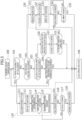
- Figure 8 is a flowchart showing an avoidance direction determination when the emergency avoidance control (EM) is activated, and corresponds to step 113 in Figure 5 .
- EM emergency avoidance control
- step 112 a determination of whether or not the lateral position (2c) of the vehicle ahead 2 is deviating (y2) to either left or right with respect to a driving position (212c) of the vehicle 1 is first made (step 1131).
- a direction of the avoidance steering is set to a direction (anti-deviation direction) opposite to the deviation (step 1141).
- a steering amount of the corrective steering can be a steering amount that gives lateral deviation corresponding to difference between width of the vehicle 1 and the deviation y2 of the vehicle ahead 2 at a braking distance by the automatic emergency braking; a corrective steering angle command is given to the EPS controller 31 via the LKA controller 15.
- step 1131; No when the vehicle 4 in the rear is present (step 1132; YES), the lateral position (y4) of the vehicle 4 in the rear is referred to (step 1133), and when the vehicle 4 in the rear is deviating (y4) to either left or right (step 1133; YES), the direction of the avoidance steering is set to a direction (anti-deviation direction) opposite to the deviation (step 1142).
- step 1133; NO When the lateral deviation (y4) of the vehicle 4 in the rear is equal to or less than the predetermined value and avoidance behavior of the vehicle 4 in the rear cannot be identified (step 1133; NO), whether or not there is a neighboring lane or a road shoulder on the road edge side is referred to on the basis of the detection information of the external sensor 21 (step 1134); when there is a neighboring lane or an effective road shoulder on either the left or right side of the vehicle's driving lane (step 1134; YES), the direction of the avoidance steering is set to a side (median strip side) opposite to the neighboring lane or road shoulder in order to increase the avoidance width for the vehicle 4 in the rear to that side (step 1143).
- step 1134 the direction of the avoidance steering is set to a road edge side within the lane so that the avoidance width for the vehicle 4 in the rear is secured on a side opposite to the road edge (step 1144).
- the direction and steering amount of the avoidance steering when the emergency avoidance control (EM) is activated are determined; when the emergency avoidance control (EM) is activated, the avoidance steering is performed at the same time as the activation of the automatic emergency braking (AEB).
- This avoidance steering is basically performed within the lane, so the steering amount is minimum, and an impact on an attitude of the vehicle 1 is small even if the avoidance steering is performed at the same time as braking at maximum deceleration; behavior stabilization control by the ESP/ABS controller 33 can cope with it.
- AKS Automatic Lane Keeping System
- the operation shifts to the automatic lane keeping system (ALKS) (step 100).
- PADS driving partially automated in-lane driving
- AKS automatic lane keeping system
- a collision risk determination is constantly made (step 101). That is, when a predicted collision time (TTC) becomes equal to or less than a predetermined value due to appearance or the like of a stopped vehicle or an obstacle due to sudden braking of a vehicle ahead, sudden interruption of another vehicle, or lane change of a vehicle ahead (steering avoidance), and it is determined that there is a collision risk, the operation shifts to the emergency avoidance control (EM) (step 110).
- TTC predicted collision time
- EM emergency avoidance control
- the automatic emergency braking (AEB) is activated as the emergency avoidance control (step 112); at the same time, the avoidance steering direction is determined (step 113; Figure 8 , steps 1131-1144) on the basis of the lateral position of a vehicle ahead (or obstacle in front) that has caused the activation of the emergency avoidance control and the lateral position of a vehicle in the rear when the vehicle in the rear is present within the rear predetermined distance.
- a direction indicator corresponding to the determined avoidance steering direction is activated to inform the vehicle in the rear of steering intention (step 114).
- the automatic emergency braking at the maximum deceleration (5 m/s 2 or more) is performed (step 114).
- the determination of whether override has occurred continues during the operation of the emergency avoidance control (automatic emergency braking) also (step 116); when a steering intervention equal to or greater than a predetermined steering override threshold value, an accelerator operation intervention equal to or greater than a predetermined accelerator override threshold value, or a brake operation intervention equal to or greater than a predetermined brake override threshold value is detected, the automatic lane keeping system (ALKS) stops, and the operation shifts to manual driving (step 140).
- AKS automatic lane keeping system
- the determination of whether override has occurred continues during the operation of the risk minimization control (MRM) also (step 134); when a steering intervention equal to or greater than a predetermined steering override threshold value, an accelerator operation intervention equal to or greater than a predetermined accelerator override threshold value, or a brake operation intervention equal to or greater than a predetermined brake override threshold value is detected, the automatic lane keeping system (ALKS) stops, and the operation shifts to manual driving (step 140).
- MRM risk minimization control
- a determination of whether the risk minimization control (MRM) is completed is made on the basis of the vehicle state (step 135). That is, when the system is made inactive or the system stops the vehicle, the risk minimization control is determined to be completed; the automatic lane keeping system (ALKS) stops (step 140), the hazard lamps keep blinking, and all vehicle systems other than that stop.
- ALKS automatic lane keeping system
- the direction of avoidance steering is determined on the basis of the lateral position (y2) of the vehicle ahead 2 (or obstacle) in the vehicle's driving lane and the avoidance steering is performed together with the emergency braking, so there is an advantage of being able to improve the probability of collision avoidance by the avoidance steering even when the braking distance for emergency stop due to an unexpected event is insufficient.
- the emergency braking is automatic or manually performed caused by the operation of the emergency brake of the vehicle 1, and the vehicle 1 moves to the right side of the vehicle ahead 2 by the avoidance steering; so, on the left side of the vehicle 1, that is, on the vehicle ahead 2 side, the avoidance width is secured.
- an inter-vehicle time which is about twice an inter-vehicle time between the vehicle 1 and the vehicle ahead 2 is secured between the vehicle ahead 2 and the vehicle in the rear; so, as long as the succeeding vehicle can avoid a collision with the vehicle 1 immediately before it, there is a high probability of being able to brake and stop before reaching a stop position of the vehicle ahead 2. Therefore, the avoidance steering described above is also advantageous in that the avoidance width can be prepared for the vehicle in the rear in order to reduce the risk that the vehicle 1 is subject to rear-end collision by the vehicle in the rear.
- the emergency avoidance control (EM) is activated, when the lateral deviation y2 of the vehicle ahead 2 is equal to or less than the predetermined value, the direction of avoidance steering is determined on the basis of the lateral position of the vehicle in the rear, and so the risk that the vehicle 1 is subject to rear-end collision by the vehicle in the rear can be reduced.
- the emergency avoidance control When the emergency avoidance control (EM) is activated, when the lateral deviation y4 of the vehicle 4 in the rear is equal to or less than the predetermined value, whether or not there is a neighboring lane or an effective road shoulder that can serve as an avoidance space for the vehicle 4 in the rear, on a road edge side in the vehicle's driving lane is referred to; when there is a neighboring lane or an effective road shoulder that can serve as the avoidance space for the vehicle 4 in the rear, the avoidance steering is performed to a direction (median strip side) opposite to those; thereby the avoidance width for the vehicle 4 in the rear is increased and the risk that the vehicle 1 is subject to rear-end collision by the vehicle 4 in the rear can be reduced.
- EM emergency avoidance control
- the avoidance steering to a road edge side is performed; thereby the avoidance width for the vehicle 4 in the rear is increased to a neighboring lane side (median strip side) opposite to the road edge, and the risk that the vehicle 1 is subject to rear-end collision by the vehicle 4 in the rear can be reduced.
- the avoidance steering may be performed across the lane marking 5L or 5R between the driving lane and a neighboring lane or road shoulder. Therefore, the avoidance steering may be performed including at least a partial movement from the vehicle 1's driving lane to the neighboring lane or road shoulder.
- the avoidance steering can be also performed including a lane change to the neighboring lane or road shoulder as long as it is confirmed that there is no other vehicle or obstacle within forward and rearward predetermined ranges in the neighboring lane or road shoulder.
- the avoidance steering control according to the present invention may be performed when the emergency avoidance control (EM) is activated during operation of another automated driving function, such as the partially automated in-lane driving system (PADS) or partially automated lane change system (PALS).
- PADS partially automated in-lane driving system
- PALS partially automated lane change system
Landscapes
- Engineering & Computer Science (AREA)
- Automation & Control Theory (AREA)
- Transportation (AREA)
- Mechanical Engineering (AREA)
- Control Of Driving Devices And Active Controlling Of Vehicle (AREA)
- Steering Control In Accordance With Driving Conditions (AREA)
- Traffic Control Systems (AREA)
Claims (5)
- Fahrsteuervorrichtung (10) für ein Fahrzeug, umfassend:einen Umweltzustand-Schätzteil (11), welcher eine Umgebung-Erkennungsfunktion zum Erkennen einer Fahrspur eines Fahrzeugs, benachbarter Spuren, anderer Fahrzeuge, welche in der Fahrspur fahren, und umgebender Umweltbedingungen sowie eine Funktion zum Erhalten des Bewegungszustands des Fahrzeugs umfasst;einen Weg-Erzeugungsteil (12) zum Erzeugen eines Zielweges auf Grundlage von Informationen, welche durch den Umweltzustand-Schätzteil (11) erhalten worden sind; undeinen Fahrzeug-Steuerteil (13), welcher dazu eingerichtet ist, eine Geschwindigkeitssteuerung und eine Lenksteuerung durchzuführen, um das Fahrzeug dazu zu bringen, dem Zielweg zu folgen, und welcher aufweist:eine Funktion zum Durchführen eines automatisierten spurgetreuen Fahrens durch Beibehalten einer festgelegten Fahrzeuggeschwindigkeit, wenn sich in der Fahrspur des Fahrzeugs kein Fahrzeug voraus befindet, und durch Beibehalten eines festgelegten Zwischenfahrzeugabstands, wenn sich ein Fahrzeug voraus befindet; undeine EM-Funktion zum Durchführen einer Not-Ausweichsteuerung, welche eine Betätigung einer Notbremse umfasst, wenn eine Kollision mit einem sich voraus befindlichen Fahrzeug oder einem Hindernis vor der Fahrspur des Fahrzeugs vorhergesagt ist,dadurch gekennzeichnet, dass, wenn die EM-Funktion aktiviert wird, wenn eine laterale Position des sich voraus befindlichen Fahrzeugs oder des Hindernisses in der Fahrspur des Fahrzeugs in Bezug auf die Fahrposition des Fahrzeugs entweder nach links oder nach rechts abweicht, eine Richtung einer Ausweichlenkung auf eine Richtung festgelegt wird, welche entgegengesetzt zu der Abweichung ist, und die Ausweichlenkung zusammen mit der Notbremsung durchgeführt wird.
- Fahrsteuervorrichtung (10) für das Fahrzeug nach Anspruch 1, wobei, wenn die EM-Funktion aktiviert wird, wenn die Abweichung der lateralen Position des sich voraus befindlichen Fahrzeugs oder eines Hindernisses gleich wie oder kleiner als ein vorbestimmter Wert ist und sich in der Fahrspur des Fahrzeugs kein hinteres Fahrzeug befindet, die Richtung der Ausweichlenkung auf eine Straßenrandseite festgelegt wird, und wenn sich in der Fahrspur des Fahrzeugs ein hinteres Fahrzeug befindet und eine laterale Position des hinteren Fahrzeugs in Bezug auf die Fahrposition des Fahrzeugs entweder nach links oder nach rechts abweicht, die Richtung der Ausweichlenkung auf eine Richtung festgelegt wird, welche entgegengesetzt zu der Abweichung des hinteren Fahrzeugs ist.
- Fahrsteuervorrichtung (10) für das Fahrzeug nach Anspruch 2, wobei, wenn sich in der Fahrspur des Fahrzeugs ein hinteres Fahrzeug befindet, die Abweichung der lateralen Position des hinteren Fahrzeugs gleich wie oder kleiner als der vorbestimmte Wert ist und weder eine benachbarte Spur noch ein Straßenbankett an der Straßenrandseite vorhanden ist, die Richtung der Ausweichlenkung auf die Straßenrandseite festgelegt wird, und wobei, wenn eine benachbarte Spur oder ein Straßenbankett an der Straßenrandseite vorhanden ist, die Richtung der Ausweichlenkung auf eine Mittelstreifenseite festgelegt wird.
- Fahrsteuervorrichtung (10) für das Fahrzeug nach einem der Ansprüche 1 bis 3, wobei die Ausweichlenkung innerhalb der Fahrspur durchgeführt wird, wenn die EM-Funktion aktiviert wird.
- Fahrsteuervorrichtung (10) für das Fahrzeug nach einem der Ansprüche 1 bis 3, wobei die Ausweichlenkung mit wenigstens einer Teilbewegung von der Fahrspur zu einer benachbarten Spur oder einem Straßenbankett durchgeführt wird, wenn die EM-Funktion aktiviert wird.
Applications Claiming Priority (1)
| Application Number | Priority Date | Filing Date | Title |
|---|---|---|---|
| JP2021155891A JP7739893B2 (ja) | 2021-09-24 | 2021-09-24 | 車両の走行制御装置 |
Publications (3)
| Publication Number | Publication Date |
|---|---|
| EP4155149A2 EP4155149A2 (de) | 2023-03-29 |
| EP4155149A3 EP4155149A3 (de) | 2023-04-05 |
| EP4155149B1 true EP4155149B1 (de) | 2025-06-25 |
Family
ID=82839164
Family Applications (1)
| Application Number | Title | Priority Date | Filing Date |
|---|---|---|---|
| EP22188868.8A Active EP4155149B1 (de) | 2021-09-24 | 2022-08-04 | Steuerungsvorrichtung für fahrzeug |
Country Status (3)
| Country | Link |
|---|---|
| EP (1) | EP4155149B1 (de) |
| JP (1) | JP7739893B2 (de) |
| HU (1) | HUE072280T2 (de) |
Families Citing this family (3)
| Publication number | Priority date | Publication date | Assignee | Title |
|---|---|---|---|---|
| KR20230173251A (ko) * | 2022-06-16 | 2023-12-27 | 현대자동차주식회사 | 최소 위험 조작을 수행하기 위한 차량 및 상기 차량의 작동 방법 |
| CN116494931B (zh) * | 2023-05-11 | 2025-09-16 | 浙江吉利控股集团有限公司 | 车辆控制方法、装置、车辆和存储介质 |
| DE102023130482A1 (de) * | 2023-11-03 | 2025-05-08 | Bayerische Motoren Werke Aktiengesellschaft | Fahrassistenzsystem und Fahrassistenzverfahren für ein Fahrzeug |
Family Cites Families (10)
| Publication number | Priority date | Publication date | Assignee | Title |
|---|---|---|---|---|
| JP2006199233A (ja) | 2005-01-24 | 2006-08-03 | Advics:Kk | 車両用安全制御装置 |
| JPWO2015008380A1 (ja) | 2013-07-19 | 2017-03-02 | 本田技研工業株式会社 | 車両の走行安全装置、車両の走行安全方法および車両の走行安全プログラム |
| EP3044061B1 (de) * | 2013-09-11 | 2019-04-17 | Robert Bosch GmbH | Modifizierung einer adaptiven geschwindigkeitskontrolle zur abschwächung von auffahrunfällen |
| CN109969116B (zh) * | 2017-12-28 | 2021-01-29 | 大众汽车(中国)投资有限公司 | 一种用于车辆的防撞方法和系统 |
| US10710580B2 (en) * | 2018-04-10 | 2020-07-14 | Valeo Schalter Und Sensoren Gmbh | Tailgating situation handling by an automated driving vehicle |
| JP6715899B2 (ja) * | 2018-09-05 | 2020-07-01 | 三菱電機株式会社 | 衝突回避装置 |
| JP7075908B2 (ja) | 2019-03-28 | 2022-05-26 | 本田技研工業株式会社 | 車両制御システム |
| KR102715606B1 (ko) * | 2019-06-11 | 2024-10-11 | 주식회사 에이치엘클레무브 | 운전자 보조 시스템, 그를 가지는 차량 및 그 제어 방법 |
| KR20210000994A (ko) * | 2019-06-26 | 2021-01-06 | 현대자동차주식회사 | 차량 및 그 제어방법 |
| JP7200871B2 (ja) | 2019-07-25 | 2023-01-10 | トヨタ自動車株式会社 | 衝突回避支援装置 |
-
2021
- 2021-09-24 JP JP2021155891A patent/JP7739893B2/ja active Active
-
2022
- 2022-08-04 HU HUE22188868A patent/HUE072280T2/hu unknown
- 2022-08-04 EP EP22188868.8A patent/EP4155149B1/de active Active
Also Published As
| Publication number | Publication date |
|---|---|
| EP4155149A2 (de) | 2023-03-29 |
| JP7739893B2 (ja) | 2025-09-17 |
| HUE072280T2 (hu) | 2025-11-28 |
| EP4155149A3 (de) | 2023-04-05 |
| JP2023047006A (ja) | 2023-04-05 |
Similar Documents
| Publication | Publication Date | Title |
|---|---|---|
| EP4052982B1 (de) | Antriebssteuerungsvorrichtung für fahrzeug | |
| US11433889B2 (en) | Driving control apparatus for vehicle | |
| US11433898B2 (en) | Driving control apparatus for vehicle | |
| US11897488B2 (en) | Autonomous driving assistance method and device | |
| US11407427B2 (en) | Driving control apparatus for vehicle | |
| US10996672B2 (en) | Driving control apparatus for vehicle | |
| EP4155152B1 (de) | Antriebssteuerungsvorrichtung für fahrzeug | |
| EP2902290B1 (de) | System zur Unterbringung eines Fußgängers während eines autonomen Fahrzeugbetriebs | |
| US9150199B2 (en) | Safety device for motor vehicles | |
| EP4155149B1 (de) | Steuerungsvorrichtung für fahrzeug | |
| US11938924B2 (en) | Driving assistance control apparatus for vehicle, driving assistance control system for vehicle, and driving assistance control method for vehicle | |
| US12233863B2 (en) | Vehicle driving assist device | |
| EP3974277B1 (de) | Antriebssteuerungsvorrichtung für fahrzeug | |
| EP4378780A1 (de) | Antriebssteuerungsvorrichtung für ein fahrzeug | |
| US12391240B2 (en) | Vehicle driving assist device | |
| US12304468B2 (en) | Vehicle driving assist device | |
| EP3974293B1 (de) | Antriebssteuerungsvorrichtung für fahrzeug | |
| EP4378778B1 (de) | Fahrsteuerungsvorrichtung für ein fahrzeug | |
| US20220177007A1 (en) | Vehicle control system | |
| EP4378779B1 (de) | Antriebssteuerungsvorrichtung für ein fahrzeug | |
| EP4600102A1 (de) | Antriebssteuerungsvorrichtung für ein fahrzeug |
Legal Events
| Date | Code | Title | Description |
|---|---|---|---|
| PUAI | Public reference made under article 153(3) epc to a published international application that has entered the european phase |
Free format text: ORIGINAL CODE: 0009012 |
|
| STAA | Information on the status of an ep patent application or granted ep patent |
Free format text: STATUS: REQUEST FOR EXAMINATION WAS MADE |
|
| PUAL | Search report despatched |
Free format text: ORIGINAL CODE: 0009013 |
|
| 17P | Request for examination filed |
Effective date: 20220804 |
|
| AK | Designated contracting states |
Kind code of ref document: A2 Designated state(s): AL AT BE BG CH CY CZ DE DK EE ES FI FR GB GR HR HU IE IS IT LI LT LU LV MC MK MT NL NO PL PT RO RS SE SI SK SM TR |
|
| AK | Designated contracting states |
Kind code of ref document: A3 Designated state(s): AL AT BE BG CH CY CZ DE DK EE ES FI FR GB GR HR HU IE IS IT LI LT LU LV MC MK MT NL NO PL PT RO RS SE SI SK SM TR |
|
| RIC1 | Information provided on ipc code assigned before grant |
Ipc: B60W 30/16 20060101ALI20230228BHEP Ipc: B60W 30/14 20060101ALI20230228BHEP Ipc: B60W 30/12 20060101ALI20230228BHEP Ipc: B60W 30/095 20120101ALI20230228BHEP Ipc: B60W 30/09 20120101AFI20230228BHEP |
|
| GRAP | Despatch of communication of intention to grant a patent |
Free format text: ORIGINAL CODE: EPIDOSNIGR1 |
|
| STAA | Information on the status of an ep patent application or granted ep patent |
Free format text: STATUS: GRANT OF PATENT IS INTENDED |
|
| INTG | Intention to grant announced |
Effective date: 20250311 |
|
| GRAS | Grant fee paid |
Free format text: ORIGINAL CODE: EPIDOSNIGR3 |
|
| GRAA | (expected) grant |
Free format text: ORIGINAL CODE: 0009210 |
|
| STAA | Information on the status of an ep patent application or granted ep patent |
Free format text: STATUS: THE PATENT HAS BEEN GRANTED |
|
| AK | Designated contracting states |
Kind code of ref document: B1 Designated state(s): AL AT BE BG CH CY CZ DE DK EE ES FI FR GB GR HR HU IE IS IT LI LT LU LV MC MK MT NL NO PL PT RO RS SE SI SK SM TR |
|
| REG | Reference to a national code |
Ref country code: GB Ref legal event code: FG4D |
|
| REG | Reference to a national code |
Ref country code: CH Ref legal event code: EP |
|
| REG | Reference to a national code |
Ref country code: CH Ref legal event code: EP |
|
| REG | Reference to a national code |
Ref country code: IE Ref legal event code: FG4D |
|
| REG | Reference to a national code |
Ref country code: DE Ref legal event code: R096 Ref document number: 602022016339 Country of ref document: DE |
|
| PG25 | Lapsed in a contracting state [announced via postgrant information from national office to epo] |
Ref country code: FI Free format text: LAPSE BECAUSE OF FAILURE TO SUBMIT A TRANSLATION OF THE DESCRIPTION OR TO PAY THE FEE WITHIN THE PRESCRIBED TIME-LIMIT Effective date: 20250625 |
|
| REG | Reference to a national code |
Ref country code: LT Ref legal event code: MG9D |
|
| PG25 | Lapsed in a contracting state [announced via postgrant information from national office to epo] |
Ref country code: NO Free format text: LAPSE BECAUSE OF FAILURE TO SUBMIT A TRANSLATION OF THE DESCRIPTION OR TO PAY THE FEE WITHIN THE PRESCRIBED TIME-LIMIT Effective date: 20250925 Ref country code: GR Free format text: LAPSE BECAUSE OF FAILURE TO SUBMIT A TRANSLATION OF THE DESCRIPTION OR TO PAY THE FEE WITHIN THE PRESCRIBED TIME-LIMIT Effective date: 20250926 |
|
| PG25 | Lapsed in a contracting state [announced via postgrant information from national office to epo] |
Ref country code: BG Free format text: LAPSE BECAUSE OF FAILURE TO SUBMIT A TRANSLATION OF THE DESCRIPTION OR TO PAY THE FEE WITHIN THE PRESCRIBED TIME-LIMIT Effective date: 20250625 |
|
| PGFP | Annual fee paid to national office [announced via postgrant information from national office to epo] |
Ref country code: HU Payment date: 20250725 Year of fee payment: 4 |
|
| PG25 | Lapsed in a contracting state [announced via postgrant information from national office to epo] |
Ref country code: HR Free format text: LAPSE BECAUSE OF FAILURE TO SUBMIT A TRANSLATION OF THE DESCRIPTION OR TO PAY THE FEE WITHIN THE PRESCRIBED TIME-LIMIT Effective date: 20250625 |
|
| PGFP | Annual fee paid to national office [announced via postgrant information from national office to epo] |
Ref country code: AT Payment date: 20251020 Year of fee payment: 4 Ref country code: FR Payment date: 20250717 Year of fee payment: 4 |
|
| PG25 | Lapsed in a contracting state [announced via postgrant information from national office to epo] |
Ref country code: RS Free format text: LAPSE BECAUSE OF FAILURE TO SUBMIT A TRANSLATION OF THE DESCRIPTION OR TO PAY THE FEE WITHIN THE PRESCRIBED TIME-LIMIT Effective date: 20250925 |
|
| PG25 | Lapsed in a contracting state [announced via postgrant information from national office to epo] |
Ref country code: LV Free format text: LAPSE BECAUSE OF FAILURE TO SUBMIT A TRANSLATION OF THE DESCRIPTION OR TO PAY THE FEE WITHIN THE PRESCRIBED TIME-LIMIT Effective date: 20250625 |
|
| REG | Reference to a national code |
Ref country code: NL Ref legal event code: MP Effective date: 20250625 |
|
| PG25 | Lapsed in a contracting state [announced via postgrant information from national office to epo] |
Ref country code: NL Free format text: LAPSE BECAUSE OF FAILURE TO SUBMIT A TRANSLATION OF THE DESCRIPTION OR TO PAY THE FEE WITHIN THE PRESCRIBED TIME-LIMIT Effective date: 20250625 |
|
| REG | Reference to a national code |
Ref country code: HU Ref legal event code: AG4A Ref document number: E072280 Country of ref document: HU |
|
| PG25 | Lapsed in a contracting state [announced via postgrant information from national office to epo] |
Ref country code: PT Free format text: LAPSE BECAUSE OF FAILURE TO SUBMIT A TRANSLATION OF THE DESCRIPTION OR TO PAY THE FEE WITHIN THE PRESCRIBED TIME-LIMIT Effective date: 20251027 |
|
| REG | Reference to a national code |
Ref country code: AT Ref legal event code: MK05 Ref document number: 1806183 Country of ref document: AT Kind code of ref document: T Effective date: 20250625 |
|
| PG25 | Lapsed in a contracting state [announced via postgrant information from national office to epo] |
Ref country code: IS Free format text: LAPSE BECAUSE OF FAILURE TO SUBMIT A TRANSLATION OF THE DESCRIPTION OR TO PAY THE FEE WITHIN THE PRESCRIBED TIME-LIMIT Effective date: 20251025 |
|
| PG25 | Lapsed in a contracting state [announced via postgrant information from national office to epo] |
Ref country code: AT Free format text: LAPSE BECAUSE OF FAILURE TO SUBMIT A TRANSLATION OF THE DESCRIPTION OR TO PAY THE FEE WITHIN THE PRESCRIBED TIME-LIMIT Effective date: 20250625 Ref country code: SM Free format text: LAPSE BECAUSE OF FAILURE TO SUBMIT A TRANSLATION OF THE DESCRIPTION OR TO PAY THE FEE WITHIN THE PRESCRIBED TIME-LIMIT Effective date: 20250625 |
|
| PG25 | Lapsed in a contracting state [announced via postgrant information from national office to epo] |
Ref country code: CZ Free format text: LAPSE BECAUSE OF FAILURE TO SUBMIT A TRANSLATION OF THE DESCRIPTION OR TO PAY THE FEE WITHIN THE PRESCRIBED TIME-LIMIT Effective date: 20250625 |
|
| PG25 | Lapsed in a contracting state [announced via postgrant information from national office to epo] |
Ref country code: PL Free format text: LAPSE BECAUSE OF FAILURE TO SUBMIT A TRANSLATION OF THE DESCRIPTION OR TO PAY THE FEE WITHIN THE PRESCRIBED TIME-LIMIT Effective date: 20250625 |
|
| PG25 | Lapsed in a contracting state [announced via postgrant information from national office to epo] |
Ref country code: EE Free format text: LAPSE BECAUSE OF FAILURE TO SUBMIT A TRANSLATION OF THE DESCRIPTION OR TO PAY THE FEE WITHIN THE PRESCRIBED TIME-LIMIT Effective date: 20250625 |
|
| PG25 | Lapsed in a contracting state [announced via postgrant information from national office to epo] |
Ref country code: SK Free format text: LAPSE BECAUSE OF FAILURE TO SUBMIT A TRANSLATION OF THE DESCRIPTION OR TO PAY THE FEE WITHIN THE PRESCRIBED TIME-LIMIT Effective date: 20250625 |
|
| PG25 | Lapsed in a contracting state [announced via postgrant information from national office to epo] |
Ref country code: ES Free format text: LAPSE BECAUSE OF FAILURE TO SUBMIT A TRANSLATION OF THE DESCRIPTION OR TO PAY THE FEE WITHIN THE PRESCRIBED TIME-LIMIT Effective date: 20250625 |
|
| PG25 | Lapsed in a contracting state [announced via postgrant information from national office to epo] |
Ref country code: RO Free format text: LAPSE BECAUSE OF FAILURE TO SUBMIT A TRANSLATION OF THE DESCRIPTION OR TO PAY THE FEE WITHIN THE PRESCRIBED TIME-LIMIT Effective date: 20250625 |
|
| REG | Reference to a national code |
Ref country code: CH Ref legal event code: H13 Free format text: ST27 STATUS EVENT CODE: U-0-0-H10-H13 (AS PROVIDED BY THE NATIONAL OFFICE) Effective date: 20260324 |
|
| PG25 | Lapsed in a contracting state [announced via postgrant information from national office to epo] |
Ref country code: MC Free format text: LAPSE BECAUSE OF FAILURE TO SUBMIT A TRANSLATION OF THE DESCRIPTION OR TO PAY THE FEE WITHIN THE PRESCRIBED TIME-LIMIT Effective date: 20250625 |
|
| PG25 | Lapsed in a contracting state [announced via postgrant information from national office to epo] |
Ref country code: DK Free format text: LAPSE BECAUSE OF FAILURE TO SUBMIT A TRANSLATION OF THE DESCRIPTION OR TO PAY THE FEE WITHIN THE PRESCRIBED TIME-LIMIT Effective date: 20250625 |
|
| PGFP | Annual fee paid to national office [announced via postgrant information from national office to epo] |
Ref country code: DE Payment date: 20260113 Year of fee payment: 4 |
|
| PG25 | Lapsed in a contracting state [announced via postgrant information from national office to epo] |
Ref country code: LU Free format text: LAPSE BECAUSE OF NON-PAYMENT OF DUE FEES Effective date: 20250804 Ref country code: IT Free format text: LAPSE BECAUSE OF FAILURE TO SUBMIT A TRANSLATION OF THE DESCRIPTION OR TO PAY THE FEE WITHIN THE PRESCRIBED TIME-LIMIT Effective date: 20250625 |
|
| PG25 | Lapsed in a contracting state [announced via postgrant information from national office to epo] |
Ref country code: CH Free format text: LAPSE BECAUSE OF NON-PAYMENT OF DUE FEES Effective date: 20250831 |
|
| PLBE | No opposition filed within time limit |
Free format text: ORIGINAL CODE: 0009261 |
|
| STAA | Information on the status of an ep patent application or granted ep patent |
Free format text: STATUS: NO OPPOSITION FILED WITHIN TIME LIMIT |