EP4378779B1 - Antriebssteuerungsvorrichtung für ein fahrzeug - Google Patents
Antriebssteuerungsvorrichtung für ein fahrzeug Download PDFInfo
- Publication number
- EP4378779B1 EP4378779B1 EP23205655.6A EP23205655A EP4378779B1 EP 4378779 B1 EP4378779 B1 EP 4378779B1 EP 23205655 A EP23205655 A EP 23205655A EP 4378779 B1 EP4378779 B1 EP 4378779B1
- Authority
- EP
- European Patent Office
- Prior art keywords
- vehicle
- function
- lane
- threshold value
- driving
- Prior art date
- Legal status (The legal status is an assumption and is not a legal conclusion. Google has not performed a legal analysis and makes no representation as to the accuracy of the status listed.)
- Active
Links
Images


Classifications
-
- B—PERFORMING OPERATIONS; TRANSPORTING
- B60—VEHICLES IN GENERAL
- B60W—CONJOINT CONTROL OF VEHICLE SUB-UNITS OF DIFFERENT TYPE OR DIFFERENT FUNCTION; CONTROL SYSTEMS SPECIALLY ADAPTED FOR HYBRID VEHICLES; ROAD VEHICLE DRIVE CONTROL SYSTEMS FOR PURPOSES NOT RELATED TO THE CONTROL OF A PARTICULAR SUB-UNIT
- B60W30/00—Purposes of road vehicle drive control systems not related to the control of a particular sub-unit, e.g. of systems using conjoint control of vehicle sub-units
- B60W30/08—Active safety systems predicting or avoiding probable or impending collision or attempting to minimise its consequences
- B60W30/09—Taking automatic action to avoid collision, e.g. braking and steering
-
- B—PERFORMING OPERATIONS; TRANSPORTING
- B60—VEHICLES IN GENERAL
- B60W—CONJOINT CONTROL OF VEHICLE SUB-UNITS OF DIFFERENT TYPE OR DIFFERENT FUNCTION; CONTROL SYSTEMS SPECIALLY ADAPTED FOR HYBRID VEHICLES; ROAD VEHICLE DRIVE CONTROL SYSTEMS FOR PURPOSES NOT RELATED TO THE CONTROL OF A PARTICULAR SUB-UNIT
- B60W30/00—Purposes of road vehicle drive control systems not related to the control of a particular sub-unit, e.g. of systems using conjoint control of vehicle sub-units
- B60W30/10—Path keeping
- B60W30/12—Lane keeping
-
- B—PERFORMING OPERATIONS; TRANSPORTING
- B60—VEHICLES IN GENERAL
- B60W—CONJOINT CONTROL OF VEHICLE SUB-UNITS OF DIFFERENT TYPE OR DIFFERENT FUNCTION; CONTROL SYSTEMS SPECIALLY ADAPTED FOR HYBRID VEHICLES; ROAD VEHICLE DRIVE CONTROL SYSTEMS FOR PURPOSES NOT RELATED TO THE CONTROL OF A PARTICULAR SUB-UNIT
- B60W30/00—Purposes of road vehicle drive control systems not related to the control of a particular sub-unit, e.g. of systems using conjoint control of vehicle sub-units
- B60W30/14—Adaptive cruise control
- B60W30/143—Speed control
-
- B—PERFORMING OPERATIONS; TRANSPORTING
- B60—VEHICLES IN GENERAL
- B60W—CONJOINT CONTROL OF VEHICLE SUB-UNITS OF DIFFERENT TYPE OR DIFFERENT FUNCTION; CONTROL SYSTEMS SPECIALLY ADAPTED FOR HYBRID VEHICLES; ROAD VEHICLE DRIVE CONTROL SYSTEMS FOR PURPOSES NOT RELATED TO THE CONTROL OF A PARTICULAR SUB-UNIT
- B60W30/00—Purposes of road vehicle drive control systems not related to the control of a particular sub-unit, e.g. of systems using conjoint control of vehicle sub-units
- B60W30/14—Adaptive cruise control
- B60W30/16—Control of distance between vehicles, e.g. keeping a distance to preceding vehicle
-
- B—PERFORMING OPERATIONS; TRANSPORTING
- B60—VEHICLES IN GENERAL
- B60W—CONJOINT CONTROL OF VEHICLE SUB-UNITS OF DIFFERENT TYPE OR DIFFERENT FUNCTION; CONTROL SYSTEMS SPECIALLY ADAPTED FOR HYBRID VEHICLES; ROAD VEHICLE DRIVE CONTROL SYSTEMS FOR PURPOSES NOT RELATED TO THE CONTROL OF A PARTICULAR SUB-UNIT
- B60W30/00—Purposes of road vehicle drive control systems not related to the control of a particular sub-unit, e.g. of systems using conjoint control of vehicle sub-units
- B60W30/18—Propelling the vehicle
- B60W30/18009—Propelling the vehicle related to particular drive situations
- B60W30/18163—Lane change; Overtaking manoeuvres
-
- B—PERFORMING OPERATIONS; TRANSPORTING
- B60—VEHICLES IN GENERAL
- B60W—CONJOINT CONTROL OF VEHICLE SUB-UNITS OF DIFFERENT TYPE OR DIFFERENT FUNCTION; CONTROL SYSTEMS SPECIALLY ADAPTED FOR HYBRID VEHICLES; ROAD VEHICLE DRIVE CONTROL SYSTEMS FOR PURPOSES NOT RELATED TO THE CONTROL OF A PARTICULAR SUB-UNIT
- B60W50/00—Details of control systems for road vehicle drive control not related to the control of a particular sub-unit, e.g. process diagnostic or vehicle driver interfaces
- B60W50/08—Interaction between the driver and the control system
- B60W50/082—Selecting or switching between different modes of propelling
-
- B—PERFORMING OPERATIONS; TRANSPORTING
- B60—VEHICLES IN GENERAL
- B60W—CONJOINT CONTROL OF VEHICLE SUB-UNITS OF DIFFERENT TYPE OR DIFFERENT FUNCTION; CONTROL SYSTEMS SPECIALLY ADAPTED FOR HYBRID VEHICLES; ROAD VEHICLE DRIVE CONTROL SYSTEMS FOR PURPOSES NOT RELATED TO THE CONTROL OF A PARTICULAR SUB-UNIT
- B60W50/00—Details of control systems for road vehicle drive control not related to the control of a particular sub-unit, e.g. process diagnostic or vehicle driver interfaces
- B60W50/08—Interaction between the driver and the control system
- B60W50/10—Interpretation of driver requests or demands
-
- B—PERFORMING OPERATIONS; TRANSPORTING
- B60—VEHICLES IN GENERAL
- B60W—CONJOINT CONTROL OF VEHICLE SUB-UNITS OF DIFFERENT TYPE OR DIFFERENT FUNCTION; CONTROL SYSTEMS SPECIALLY ADAPTED FOR HYBRID VEHICLES; ROAD VEHICLE DRIVE CONTROL SYSTEMS FOR PURPOSES NOT RELATED TO THE CONTROL OF A PARTICULAR SUB-UNIT
- B60W60/00—Drive control systems specially adapted for autonomous road vehicles
- B60W60/005—Handover processes
- B60W60/0053—Handover processes from vehicle to occupant
-
- B—PERFORMING OPERATIONS; TRANSPORTING
- B60—VEHICLES IN GENERAL
- B60W—CONJOINT CONTROL OF VEHICLE SUB-UNITS OF DIFFERENT TYPE OR DIFFERENT FUNCTION; CONTROL SYSTEMS SPECIALLY ADAPTED FOR HYBRID VEHICLES; ROAD VEHICLE DRIVE CONTROL SYSTEMS FOR PURPOSES NOT RELATED TO THE CONTROL OF A PARTICULAR SUB-UNIT
- B60W2520/00—Input parameters relating to overall vehicle dynamics
- B60W2520/10—Longitudinal speed
- B60W2520/105—Longitudinal acceleration
-
- B—PERFORMING OPERATIONS; TRANSPORTING
- B60—VEHICLES IN GENERAL
- B60W—CONJOINT CONTROL OF VEHICLE SUB-UNITS OF DIFFERENT TYPE OR DIFFERENT FUNCTION; CONTROL SYSTEMS SPECIALLY ADAPTED FOR HYBRID VEHICLES; ROAD VEHICLE DRIVE CONTROL SYSTEMS FOR PURPOSES NOT RELATED TO THE CONTROL OF A PARTICULAR SUB-UNIT
- B60W2540/00—Input parameters relating to occupants
- B60W2540/18—Steering angle
-
- B—PERFORMING OPERATIONS; TRANSPORTING
- B60—VEHICLES IN GENERAL
- B60W—CONJOINT CONTROL OF VEHICLE SUB-UNITS OF DIFFERENT TYPE OR DIFFERENT FUNCTION; CONTROL SYSTEMS SPECIALLY ADAPTED FOR HYBRID VEHICLES; ROAD VEHICLE DRIVE CONTROL SYSTEMS FOR PURPOSES NOT RELATED TO THE CONTROL OF A PARTICULAR SUB-UNIT
- B60W2552/00—Input parameters relating to infrastructure
- B60W2552/30—Road curve radius
-
- B—PERFORMING OPERATIONS; TRANSPORTING
- B60—VEHICLES IN GENERAL
- B60W—CONJOINT CONTROL OF VEHICLE SUB-UNITS OF DIFFERENT TYPE OR DIFFERENT FUNCTION; CONTROL SYSTEMS SPECIALLY ADAPTED FOR HYBRID VEHICLES; ROAD VEHICLE DRIVE CONTROL SYSTEMS FOR PURPOSES NOT RELATED TO THE CONTROL OF A PARTICULAR SUB-UNIT
- B60W2555/00—Input parameters relating to exterior conditions, not covered by groups B60W2552/00, B60W2554/00
- B60W2555/20—Ambient conditions, e.g. wind or rain
Definitions
- a driving control apparatus for a vehicle that executes a strong brake control to set the relative speed with an obstacle to "0" when it is determined that there is a high probability of collision with the obstacle is disclosed in Patent Literature 1, for example.
- Steering intervention for collision avoidance is permitted when the predicted travel distance until the relative speed becomes "0" is longer than the relative distance to the obstacle.
- the strong brake control is activated, steering intervention is permitted, and when the predicted collision time with an obstacle has fallen to or below a time threshold, the emergency steering control is executed to avoid a collision with the obstacle.
- a driving control apparatus for a vehicle can start performing an emergency avoidance control quickly when shifting to an EM function in an automated lane keeping system.
- the driving control apparatus for a vehicle has the function of an automated lane keeping system (ALKS) that recognizes the position of the vehicle and the surrounding environment of the vehicle using external sensors such as radars and cameras, and controls vehicle speed and steering to perform automatic driving in a single lane at or below a predetermined speed (for example, 60 km/h).
- ALKS automated lane keeping system
- the ALKS is a system combining an adaptive cruise control system (ACCS) and a lane keeping assistance system (LKAS).
- the main functions of the ALKS include lane marking recognition, in-lane vehicle position recognition, target vehicle speed and target path generation, vehicle speed control and in-lane path following control, automated steering, and the like.
- vehicle speed control and in-lane path following control mean the control of vehicle speed and steering necessary to achieve a target vehicle speed and target path.
- Automated steering means that steering is performed using electric power steering with a steering torque necessary to achieve a target steering angle for path following.
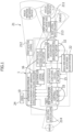
- the controller/actuator group for speed control and steering control includes an electric power steering (EPS) controller 31 for steering control, an engine controller 32 for acceleration/deceleration rate control, and an ESP/ABS controller 33.
- EPS electric power steering
- An ESP includes an anti-lock braking system (ABS) to form a stability control system (vehicle behavior stabilization control system).
- the environmental condition estimating part 11 is further configured to determine whether an obstacle ahead in the lane of the vehicle is a stationary object or a moving object.
- a stationary object is an obstacle the absolute location of which is not moving, such as a parked vehicle, safety equipment for road construction, or the like, for example.
- a moving object is an obstacle the absolute location of which is moving, such as another vehicle ahead, a pedestrian, an oncoming vehicle, or the like, for example.
- An obstacle can be determined to be a stationary object or to be a moving object on the basis of the relative speed between the vehicle 1 and the obstacle, for example.
- the environmental condition estimating part 11 detects the optical flow of obstacles existing ahead of the vehicle on the basis of image data of the area ahead of the vehicle acquired by the external sensor 21 (camera 212).
- Optical flow is a vector representation of the movement of an object between image frames in a plurality of temporally consecutive image frames in a video image. Therefore, by detecting the optical flow, the movement direction of an obstacle can be determined. If an obstacle is moving so as to approach the vehicle 1 in the lane of the vehicle, the environmental condition estimating part 11 can determine that the obstacle is an oncoming vehicle.
- the EM path-setting part 122 generates an emergency target path (target path for EM) to guide and bring the vehicle to a stop at the target stop position in the emergency avoidance control for avoiding a collision with an obstacle.
- the EM path-setting part 122 is further configured to pre-set an emergency evacuation area for setting a target stop position on the target path for the ALKS in case the emergency avoidance control is executed.
- the EM path-setting part 122 sets the target stop position according to the activation mode of the EM function as described later.
- the path generating part 12 is further configured to determine whether a poor visibility area, in which visibility is poor, exists on the target path on which the vehicle 1 travels.
- the ALKS is a system combining an adaptive cruise control system (ACCS) and a lane keeping assistance system (LKAS), enabling automated lane keeping driving (automated in-lane driving) in the state in which the ACCS by the ACC controller 15 and the LKAS by the LKA controller 16 are both active.
- ACCS adaptive cruise control system
- LKAS lane keeping assistance system
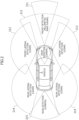
- the path generating part 12 of the automated driving controller 10, specifically the ALKS path-setting part 121, generates a target path and a target vehicle speed for activating the ALKS on the basis of external information (lanes, vehicle location, the positions and speeds of other vehicles traveling in the vehicle's own driving lane and the neighboring lanes, and the presence or absence of pedestrians and other obstacles) acquired by the external sensor 21 and internal information (vehicle speed, yaw rate, acceleration rate) acquired by the internal sensor 22.
- external information lanes, vehicle location, the positions and speeds of other vehicles traveling in the vehicle's own driving lane and the neighboring lanes, and the presence or absence of pedestrians and other obstacles
- internal information vehicle speed, yaw rate, acceleration rate
- the ESP/ABS controller 33 Upon receiving a deceleration command from the ACC controller 15, the ESP/ABS controller 33 controls the vehicle speed by outputting a hydraulic command to the actuator and controlling the braking force of the brake 43. Also, upon receiving an acceleration/deceleration command from the ACC controller 15, the engine controller 32 controls the actuator output (throttle position) to thereby issue a torque command to the engine 42 so as to control the driving force and to control the vehicle speed.
- the adaptive cruise control system functions as a combination of hardware and software, such as a millimeter wave radar serving as the front detection means 211 included in the external sensor 21, the ACC controller 15, the engine controller 32, and the ESP/ABS controller 33.
- the lane keeping assistance system detects the lane markings and the vehicle location by the environmental condition estimating part 11 of the automated driving controller 10 on the basis of image data obtained by the external sensor 21 (cameras 212 and 215), and performs steering control by the EPS controller 31 via the LKA controller 16 so as to be able to drive in the lane center.
- LKAS lane keeping assistance system
- the ALKS executes an automated lane keeping function by combining longitudinal control (speed control and inter-vehicle distance control) by the ACC controller 15 and lateral control (steering control and lane keeping control) by the LKA controller 16.
- the emergency maneuver (EM) function is activated and the emergency avoidance control is executed.
- the EM function includes autonomous emergency braking (AEB) for collision avoidance or collision mitigation.
- the visible distance at which an obstacle is visible is determined on the basis of road information about the road alignment, landmarks that exist along the road, and the like.
- Information about road alignment is information about the shape of the road and includes the radius of curvature of the road and the vertical grade, for example.
- Landmarks include both natural landforms and manmade structures, and information about landmarks that exist along the road includes information about the shapes, sizes, and the like of structures that exist near the road, such as sidewalls and buildings, for example.
- the prescribed value for determining the degree of visibility can be defined as, for example, the braking distance required for the vehicle 1 to come to a braking stop without colliding with an obstacle after detecting the obstacle on the target path.
- the braking distance is determined on the basis of road information about the radius of curvature and vertical grade of the road, landmarks that exist along the road, and the like, as well as speed limit information on the target path.
- An area in which the visible distance is less than the braking distance is determined to be a poor visibility area in which the degree of visibility of the road is poor.
- the EM path-setting part 122 of the path generating part 12 of the automated driving controller 10 is configured to set, on the basis of the location of the vehicle acquired by the environmental condition estimating part 11 and map information on the vehicle surroundings acquired from the map information database 23, an emergency evacuation area on the target path in case of activation of the EM function while the automated lane keeping driving by the ALKS is being executed. That is, the EM path-setting part 122 also functions as an evacuation area setting part.
- the EM path-setting part 122 estimates, on the basis of the vehicle location and the map information on the vehicle surroundings, the road shape on which the vehicle 1 is traveling and sets an emergency evacuation area corresponding to the road shape.
- the emergency evacuation area is set on the target path ahead in the direction of travel of the vehicle, and is constantly updated as the vehicle 1 moves.
- Figure 4 illustrates state transitions of control in the ALKS.
- the environmental condition estimating part 11 determines whether there are deviations from the system operating conditions and detects whether there are abnormalities or faults in the system, on the basis of the driving state of the vehicle, the surrounding environmental conditions, the driver state, and the like.
- an operation takeover request (transition demand (TD)) is issued from the system to the driver. If the driver takes over driving operations within a prescribed time (for example, 10 seconds) after the operation takeover request (TD), automated lane keeping driving transitions to manual driving (the ALKS stops).
- TD transition demand
- a minimal risk maneuver (MRM) function is activated and risk minimization control is performed.
- the MRM function means a function that automatically shifts to a minimal risk condition when the driver is unable to take over operations.
- the MRM includes control to evacuate to the shoulder through automated steering or to decelerate to a stop in the lane (safe stop) by the automated driving controller 10.
- the EM function described above is activated and the emergency avoidance control is executed.
- the brake 43 is controlled via the ACC controller 15 and the steering mechanism 41 is controlled via the LKA controller 16 so that the vehicle 1 is guided to a stop at the target stop position set by the EM path-setting part 122.
- the driving control apparatus described above is configured to allow an override due to a control intervention by the driver while the ALKS is active or while the EM function and the MRM function are active. That is, the override function is a function that stops active functions and transfers control or authority to the driver if there a control intervention equal to or greater than a predetermined threshold by the driver while the ALKS, the EM function, and the MRM function are active.
- the override function is executable even while the EM function is active. If there is a switch from the state in which automated lane keeping driving was being performed by the ALKS to a hazard avoidance mode in which the EM function is executed, there is a possibility that the emergency autonomous braking by the EM function may cause the driver to panic. Consequently, if an excessive override, such as excessive acceleration/deceleration operations or excessive steering operations, is performed by the panicked driver, the behavior of the vehicle 1 may become unstable or the vehicle 1 may suddenly approach a nearby obstacle or nearby structure.
- the driving control apparatus if the EM function is activated while the ALKS is active, an override due to excessive driving operations by the driver is suppressed by changing the override threshold values to values greater than normal. Furthermore, if the EM function is activated due to the detection of a moving object, the override threshold values are set to even greater values.
- the override threshold values include the acceleration/deceleration override threshold values related to acceleration/deceleration operations and the steering override threshold value related to steering operation.
- the acceleration/deceleration override threshold values include an accelerator override threshold value related to an accelerator operation and a brake override threshold value related to a brake operation.
- an accelerator override is executed.
- the accelerator operation by the driver is given priority over the automated lane keeping driving by the ALKS.
- an engine torque command value obtained from an engine torque map set according to the vehicle speed and the gear stage is set as an accelerator override threshold value OEd.
- a threshold value for the case of additive steering and a threshold value for the case of subtractive steering are set separately.
- a steering torque corresponding to a steering angle at which a virtual lateral displacement y't for reaching a virtual lateral position after t seconds becomes yt+ ⁇ is set as the steering override threshold value OTd.
- ⁇ is a constant determined on the basis of the vehicle speed
- An accelerator override threshold value OEemb when the EM is activated due to a moving object is set to a value even greater than the above-described accelerator override threshold value OEema when the EM is activated due to a stationary object. That is, OEemb > OEema > OEd.
- a steering override threshold value OTemb when the EM is activated due to a moving object is set to a value even greater than the above-described steering override threshold value OTema when the EM is activated due to a stationary object, in the case of both additive steering and subtractive steering. That is, OTemb > OTema > OTd.
- Figure 5 illustrates a flowchart explaining the flow of control of the EM function according to the present embodiment.
- the EM path-setting part 122 of the path generating part 12 sets an emergency evacuation area in a poor visibility area on the target path on the basis of the vehicle location acquired by the environmental condition estimating part 11 and the map information on the vehicle surroundings acquired from the map information database 23 (step S102). No emergency evacuation area is set in an area with good visibility on the target path.
- the emergency evacuation area is constantly updated while the ALKS is active.
- the environmental condition estimating part 11 determines the possibility or probability of a collision with an obstacle in the vehicle surroundings on the basis of the information on obstacles detected by the external sensor 21 and the vehicle information on the vehicle 1 detected by the internal sensor 22 (step S104).
- the probability of a collision with the obstacle is determined to be high, and control shifts to the EM function to execute the emergency avoidance control (step S110). If the predicted time to collision TTC with an obstacle is greater than the prescribed value and the probability of a collision is determined to be low, the flow proceeds to step S103. Note that if the possibility of a collision with an obstacle is determined to be high, the environmental condition estimating part 11 also determines whether the obstacle is a stationary object or a moving object.
- step S111 When control shifts to the EM function, a collision possibility flag is raised (step S111) and activation of the EM function, including activation of the autonomous emergency braking for collision avoidance or collision mitigation, is started (step S112).
- the EM path-setting part 122 of the path generating part 12 sets a target stop position according to the activation mode of the EM function and whether the visibility is good or poor (step S113). Specifically, if the reason for activation of the EM function is that there is a stationary object such as a parked vehicle on the target path, that is, if the EM function is activated by the detection of a stationary object, the target stop position is set inside the driving lane of the vehicle 1.
- the EM path-setting part 122 If the target stop position is set inside the driving lane, the EM path-setting part 122 generates a target path to the target stop position on the basis of the location and speed of the vehicle 1 so as to perform an in-lane stop by braking control. On the other hand, if the target stop position is set inside the emergency evacuation area, the EM path-setting part 122 generates a target path to the target stop position on the basis of the location and speed of the vehicle 1 so as to guide the vehicle 1 to a stop by braking control and steering control.
- braking control is performed at the maximum deceleration rate of the system.
- the target stop position is set inside an emergency evacuation area based on the side edge of the road, it is preferable to perform braking control at a deceleration rate for emergency avoidance control that is smaller than the maximum deceleration rate of the system. This is in consideration of the safety of the behavior of the vehicle 1 when stopping the vehicle 1 at the target stop position by steering control and braking control.
- the normal override threshold values (OEd, OPd, OTd) are changed to the override threshold values (OEema, OPema, OTema) for the EM activation due to a stationary object.
- a driving control apparatus for a vehicle comprises: an environmental condition estimating part 11 including a surrounding recognition function for recognizing a driving lane of the vehicle, neighboring lanes, other vehicles in each of the lanes, and a surrounding environment, and a function for obtaining a state of movement of the vehicle; a path generating part 12 for generating a target path on the basis of information obtained by the environmental condition estimating part 11; and a vehicle control part 13 configured to perform speed control and steering control for making the vehicle follow the target path.
- the path generating part 12 has an EM path-setting part (evacuation area setting part) 122 that sets an emergency evacuation area on the target path in case of activation of the EM function on the basis of location information and map information of the vehicle 1 while the in-lane automated driving function is active, and the EM path-setting part 122 is configured to select a target stop position from inside the emergency evacuation area while the EM function is active.
- EM path-setting part evacuation area setting part
- the path generating part 12 is configured to determine whether a poor visibility area in which a degree of visibility of the road is less than a prescribed value exists on the target path. If a poor visibility area is determined to exist, the EM path-setting part 122 sets, on the basis of location information and map information of the vehicle, an emergency evacuation area on the target path in case of activation of the EM function.
- the vehicle 1 is traveling through a poor visibility area with poor visibility on the road, there is a possibility that a delay may occur in the detection of the situation ahead in the lane of the vehicle by the system compared to the case of traveling in an area with good visibility. Accordingly, by setting in advance an emergency evacuation area in a poor visibility area on the target path in case of activation of the EM function, the emergency avoidance control can be executed quickly when the EM function is activated. Also, by limiting the setting of the emergency evacuation area to a poor visibility area, it is also possible to reduce the computational load on the automated driving controller 10 compared to the case in which the emergency evacuation area is set constantly.
- the degree of visibility is defined as the visible distance at which an obstacle on the road is visible, and is determined on the basis of road information about the radius of curvature and the vertical grade of the road, and landmarks that exist along the road.
- the prescribed value for determining the degree of visibility is defined as the braking distance required to come to a braking stop without colliding with an obstacle after detecting the obstacle on the target path, and is determined on the basis of road information and speed limit information on the target path.
- the path generating part 12 determines that a poor visibility area exists if the visible distance is less than the braking distance.
- the degree of visibility is determined to be a visible distance based on road information and the existence of a poor visibility area is determined through a comparison with the braking distance required for the vehicle 1 to come to a braking stop without colliding with an obstacle on the basis of road information and speed limit information, the existence of a poor visibility area can be determined objectively in advance, without using information from the external sensor 21 or the like.
- the EM path-setting part 122 sets an emergency evacuation area to include the lateral width of the vehicle 1 with respect to the side edge of the road in the direction of travel of the vehicle 1.
- the emergency evacuation area the narrowest possible area, taking into account the lateral width of the vehicle 1 from the side edge of the road, the vehicle 1 can be stopped in an area on the side edge of the road in the emergency avoidance control. This arrangement makes it possible to lower the risk of collision when the EM function is activated due to the appearance of an oncoming vehicle or the like from the opposite lane, for example.
- the environmental condition estimating part 11 is configured to determine whether the obstacle that causes the EM function to be activated is a stationary object or a moving object, and the EM path-setting part 122 is configured to set a target stop position inside the emergency evacuation area if the obstacle is a moving object, and to set a target stop position inside the driving lane of the vehicle 1 if the obstacle is a stationary object.
- the reason for activation of the EM function is a stationary object such as a parked vehicle on the target path, a target stop position is set inside the driving lane and an in-lane stop is performed by braking control.
- the reason for activation of the EM function is a moving object such as an oncoming vehicle or a pedestrian on the target path, and in particular, if the EM function is activated due to a moving object in a poor visibility area, the vehicle 1 is guided to a stop by braking control and steering control at a target stop position inside an emergency evacuation area set with respect to the side edge of the road.
- emergency avoidance control is executed using not only braking control, but also steering control.
- An emergency avoidance control combining braking control and steering control is also executed in cases such as when a moving object is approaching the vehicle 1. In this way, by changing the target stop position depending on the reason for activation of the EM function, an effective emergency avoidance control corresponding to the EM activation reason or cause can be performed.
- the driving control apparatus for a vehicle further includes an override function that, if there is a control intervention equal to or greater than a prescribed threshold value by the driver while the in-lane automated driving function or the EM function is active, stops the active function and transfers control to the driver, the override function being configured such that a first threshold value is set as the prescribed threshold value while the in-lane automated driving function is active, a second threshold value is set as the prescribed threshold value when the EM function is activated and the obstacle is a stationary object, and a third threshold value is set as the prescribed threshold value when the EM function is activated and the obstacle is a moving object, the third threshold value being greater than the second threshold value, and the second threshold value being greater than the first threshold value.
- the EM function is activated due to the appearance of a moving object such as an oncoming vehicle, for example, while the in-lane automated driving function by the ALKS is active, there is a possibility that the driver will panic and perform excessive driving operations, which may cause an override to be executed unintentionally. If an excessive override operation is executed, there is a possibility of creating a situation in which the vehicle 1 intrudes into the opposite lane or veers off the road.
- the first threshold value as the prescribed threshold value while the in-lane automated driving function is active
- setting the third threshold value greater than the second threshold value when the EM function is activated due to a moving object an excessive override can be suppressed.
- an override by the driver is suppressed more than when the EM function is activated due to a stationary object, and therefore the safety functions of the ALKS can be used to achieve the emergency avoidance control.
- the handover of driving operations is suppressed when the EM is activated during which driving operations are burdensome, the risks arising from the handover of driving operations to the driver can be suppressed.
Landscapes
- Engineering & Computer Science (AREA)
- Automation & Control Theory (AREA)
- Transportation (AREA)
- Mechanical Engineering (AREA)
- Human Computer Interaction (AREA)
- Traffic Control Systems (AREA)
- Control Of Driving Devices And Active Controlling Of Vehicle (AREA)
Claims (6)
- Fahrsteuerungsvorrichtung für ein Fahrzeug (1), umfassend:ein Umgebungsbedingungsschätzungsteil (11), welches eine Umgebungserkennungsfunktion für ein Erkennen einer Fahrspur des Fahrzeugs, benachbarter Spuren, anderer Fahrzeuge in jeder der Spuren und einer Umgebung und eine Funktion für ein Erhalten eines Zustands einer Bewegung des Fahrzeugs umfasst;ein Wegerzeugungsteil (12), welches dazu eingerichtet ist, einen Zielweg auf Grundlage von Informationen zu erzeugen, welche durch das Umgebungsbedingungsschätzungsteil (11) erhalten sind; undein Fahrzeugsteuerungsteil (13), welches dazu eingerichtet ist, eine Geschwindigkeitssteuerung und eine Lenksteuerung für das Fahrzeug (1) durchzuführen, um dem Zielweg zu folgen,wobei die Fahrsteuerungsvorrichtung für ein Fahrzeug (1) aufweist:eine automatisierte In-Spur-Fahrfunktion, welche ein automatisiertes In-Spur-Fahren für ein Halten einer festgelegten Geschwindigkeit durchführt, wenn kein anderes Fahrzeug voraus in der Spur des Fahrzeugs gegenwärtig ist, und für ein Halten einer festgelegten Zwischenfahrzeugdistanz, wenn voraus ein anderes Fahrzeug gegenwärtig ist; undeine EM-Funktion, welche eine Notsituationsverhinderungssteuerung ausführt, welche eine Aktivierung eines Notsituationsbremsens umfasst, wenn eine Kollision mit einem Hindernis, welches voraus in der Spur des Fahrzeugs gegenwärtig ist, vorausgesagt ist, dadurch gekennzeichnet, dass:das Wegerzeugungsteil (12) ein Evakuierungsbereich-Festlegeteil (122) aufweist, welches einen Notsituationsevakuierungsbereich auf dem Zielweg festlegt, für den Fall einer Aktivierung der EM-Funktion auf Grundlage von Standortinformationen und Karteninformationen des Fahrzeugs (1), während die automatisierte In-Spur-Fahrfunktion aktiv ist; unddas Evakuierungsbereich-Festlegeteil (122) dazu eingerichtet ist, eine Zielstoppposition von innerhalb des Notsituationsevakuierungsbereichs auszuwählen, während die EM-Funktion aktiv ist.
- Fahrsteuerungsvorrichtung für ein Fahrzeug (1) nach Anspruch 1, wobei:das Wegerzeugungsteil (12) dazu eingerichtet ist, zu bestimmen, ob ein schlechter Sichtbarkeitsbereich, in welchem ein Grad einer Sichtbarkeit einer Straße niedriger als ein vorgeschriebener Wert ist, auf dem Zielweg existiert; undwenn der schlechte Sichtbarkeitsbereich als existierend bestimmt ist, das Evakuierungsbereich-Festlegeteil (122), auf Grundlage von Standortinformationen und Karteninformationen des Fahrzeugs (1), einen Notsituationsevakuierungsbereich auf dem Zielweg festlegt, für den Fall einer Aktivierung der EM-Funktion.
- Fahrsteuerungsvorrichtung für ein Fahrzeug (1) nach Anspruch 2, wobei:der Grad einer Sichtbarkeit als eine sichtbare Distanz definiert ist, bei welcher ein Hindernis auf der Straße sichtbar ist, und auf Grundlage der Straßeninformationen um einen Radius einer Krümmung und einer vertikalen Neigung der Straße und Orientierungspunkten bestimmt ist, welche entlang der Straße existieren;der vorgeschriebene Wert als eine Bremsdistanz definiert ist, welche benötigt wird, um zu einem Bremsstopp zu gelangen, ohne mit einem Hindernis zu kollidieren, nach einem Detektieren des Hindernisses auf dem Zielweg, und auf Grundlage der Straßeninformationen und Geschwindigkeitsbegrenzungsinformationen auf dem Zielweg bestimmt ist; unddas Wegerzeugungsteil (12) bestimmt, dass der schlechte Sichtbarkeitsbereich existiert, wenn die sichtbare Distanz geringer als die Bremsdistanz ist.
- Fahrsteuerungsvorrichtung für ein Fahrzeug (1) nach Anspruch 2, wobei das Evakuierungsbereich-Festlegeteil (122) den Notsituationsevakuierungsbereich festlegt, um eine seitliche Breite des Fahrzeugs (1) in Bezug zu einem Seitenrand der Straße in einer Fahrtrichtung des Fahrzeugs festzulegen.
- Fahrsteuerungsvorrichtung für ein Fahrzeug (1) nach einem der Ansprüche 2 bis 4, wobei:das Umgebungsbedingungsschätzungsteil (11) bestimmt, ob das Hindernis, welches die EM-Funktion veranlasst, aktiviert zu sein, ein feststehendes Objekt oder ein bewegtes Objekt ist; unddas Evakuierungsbereich-Festlegeteil (122) dazu eingerichtet ist, eine Zielstoppposition innerhalb des Notsituationsevakuierungsbereichs festzulegen, wenn das Hindernis das bewegte Objekt ist, und eine Zielstoppposition innerhalb der Fahrspur des Fahrzeugs (1) festzulegen, wenn das Hindernis das feststehende Objekt ist.
- Fahrsteuerungsvorrichtung für ein Fahrzeug (1) nach Anspruch 5, ferner umfassend:
eine Aufhebungsfunktion, welche, wenn eine Steuerungsintervention gleich oder größer einem vorbestimmten Schwellenwert durch einen Fahrer besteht, während die automatisierte In-Spur-Fahrfunktion oder die EM-Funktion aktiv ist, die aktive Funktion stoppt und eine Steuerung an den Fahrer überführt, wobei:die Aufhebungsfunktion derart eingerichtet ist, dass ein erster Schwellenwert als der vorbeschrieben Schwellenwert festgelegt ist, während die automatisierte In-Spur-Fahrfunktion aktiv ist, ein zweiter Schwellenwert als der vorbeschrieben Schwellenwert festgelegt ist, wenn die EM-Funktion aktiviert ist und das Hindernis das feststehende Objekt ist, und ein dritter Schwellenwert als der vorbeschriebene Schwellenwert festgelegt ist, wenn die EM-Funktion aktiviert ist und das Hindernis das bewegte Objekt ist; undder dritte Schwellenwert größer als der zweite Schwellenwert ist und der zweite Schwellenwert größer als der erste Schwellenwert ist.
Applications Claiming Priority (1)
| Application Number | Priority Date | Filing Date | Title |
|---|---|---|---|
| JP2022191846A JP2024079110A (ja) | 2022-11-30 | 2022-11-30 | 車両の走行制御装置 |
Publications (2)
| Publication Number | Publication Date |
|---|---|
| EP4378779A1 EP4378779A1 (de) | 2024-06-05 |
| EP4378779B1 true EP4378779B1 (de) | 2025-04-16 |
Family
ID=88511515
Family Applications (1)
| Application Number | Title | Priority Date | Filing Date |
|---|---|---|---|
| EP23205655.6A Active EP4378779B1 (de) | 2022-11-30 | 2023-10-24 | Antriebssteuerungsvorrichtung für ein fahrzeug |
Country Status (3)
| Country | Link |
|---|---|
| EP (1) | EP4378779B1 (de) |
| JP (1) | JP2024079110A (de) |
| HU (1) | HUE071350T2 (de) |
Families Citing this family (1)
| Publication number | Priority date | Publication date | Assignee | Title |
|---|---|---|---|---|
| JP2024034044A (ja) * | 2022-08-31 | 2024-03-13 | トヨタ自動車株式会社 | 運転支援装置、運転支援方法、及び運転支援プログラム |
Family Cites Families (11)
| Publication number | Priority date | Publication date | Assignee | Title |
|---|---|---|---|---|
| JPH10124799A (ja) * | 1996-10-16 | 1998-05-15 | Toyota Motor Corp | 車両用走行安全検知装置及び車両用走行制御装置 |
| US10832061B2 (en) * | 2016-07-22 | 2020-11-10 | Hitachi Automotive Systems, Ltd. | Traveling road boundary estimation apparatus and traveling assistance system using same |
| KR102485348B1 (ko) * | 2017-12-28 | 2023-01-05 | 현대자동차주식회사 | 차량 주행보조기능의 자동제어 장치 및 방법 |
| KR20200081530A (ko) * | 2018-12-19 | 2020-07-08 | 주식회사 만도 | 자율 주행 차량의 안전 제어 시스템 및 방법 |
| JP7168509B2 (ja) * | 2019-03-29 | 2022-11-09 | 本田技研工業株式会社 | 車両制御システム |
| JP7545660B2 (ja) * | 2020-09-24 | 2024-09-05 | スズキ株式会社 | 車両の走行制御装置 |
| JP7610387B2 (ja) | 2020-10-02 | 2025-01-08 | 株式会社Subaru | 車両の走行制御装置 |
| JP7327371B2 (ja) | 2020-12-09 | 2023-08-16 | トヨタ自動車株式会社 | 車両制御システム及び自動運転車両並びに車両制御方法 |
| JP7573172B2 (ja) * | 2021-03-03 | 2024-10-25 | スズキ株式会社 | 車両の走行制御装置 |
| JP7648423B2 (ja) * | 2021-03-31 | 2025-03-18 | 本田技研工業株式会社 | 車両制御装置及び車両、並びに、車両制御装置の制御方法及びプログラム |
| CN115402305B (zh) * | 2022-11-01 | 2023-02-03 | 中国第一汽车股份有限公司 | 扭矩补偿方法、装置、存储介质及电子装置 |
-
2022
- 2022-11-30 JP JP2022191846A patent/JP2024079110A/ja active Pending
-
2023
- 2023-10-24 HU HUE23205655A patent/HUE071350T2/hu unknown
- 2023-10-24 EP EP23205655.6A patent/EP4378779B1/de active Active
Also Published As
| Publication number | Publication date |
|---|---|
| JP2024079110A (ja) | 2024-06-11 |
| EP4378779A1 (de) | 2024-06-05 |
| HUE071350T2 (hu) | 2025-08-28 |
Similar Documents
| Publication | Publication Date | Title |
|---|---|---|
| US11897488B2 (en) | Autonomous driving assistance method and device | |
| EP4052982B1 (de) | Antriebssteuerungsvorrichtung für fahrzeug | |
| JP7189509B2 (ja) | 車両の走行制御装置 | |
| EP4378780A1 (de) | Antriebssteuerungsvorrichtung für ein fahrzeug | |
| US11186275B2 (en) | Vehicle control system | |
| US20230234574A1 (en) | Vehicle driving assist device | |
| US11938924B2 (en) | Driving assistance control apparatus for vehicle, driving assistance control system for vehicle, and driving assistance control method for vehicle | |
| US20110313665A1 (en) | Method for Automatically Detecting a Driving Maneuver of a Motor Vehicle and a Driver Assistance System Comprising Said Method | |
| US12233863B2 (en) | Vehicle driving assist device | |
| US20210394752A1 (en) | Traveling Control Device, Vehicle, and Traveling Control Method | |
| JP2020144789A (ja) | 車両の走行制御装置 | |
| US10994726B2 (en) | Vehicle control system | |
| JP7813171B2 (ja) | 車両の運転支援装置、及び、車両の運転支援システム | |
| US20220144259A1 (en) | Method and control device for vehicle collision prevention | |
| EP4155152B1 (de) | Antriebssteuerungsvorrichtung für fahrzeug | |
| EP4378778B1 (de) | Fahrsteuerungsvorrichtung für ein fahrzeug | |
| JP7813145B2 (ja) | 車両の運転支援装置 | |
| EP3974277B1 (de) | Antriebssteuerungsvorrichtung für fahrzeug | |
| EP4155149B1 (de) | Steuerungsvorrichtung für fahrzeug | |
| US12304468B2 (en) | Vehicle driving assist device | |
| EP3974293B1 (de) | Antriebssteuerungsvorrichtung für fahrzeug | |
| EP4378779B1 (de) | Antriebssteuerungsvorrichtung für ein fahrzeug | |
| US20240404403A1 (en) | Vehicle control system and vehicle control method | |
| EP4600102A1 (de) | Antriebssteuerungsvorrichtung für ein fahrzeug |
Legal Events
| Date | Code | Title | Description |
|---|---|---|---|
| PUAI | Public reference made under article 153(3) epc to a published international application that has entered the european phase |
Free format text: ORIGINAL CODE: 0009012 |
|
| STAA | Information on the status of an ep patent application or granted ep patent |
Free format text: STATUS: REQUEST FOR EXAMINATION WAS MADE |
|
| 17P | Request for examination filed |
Effective date: 20231024 |
|
| AK | Designated contracting states |
Kind code of ref document: A1 Designated state(s): AL AT BE BG CH CY CZ DE DK EE ES FI FR GB GR HR HU IE IS IT LI LT LU LV MC ME MK MT NL NO PL PT RO RS SE SI SK SM TR |
|
| GRAP | Despatch of communication of intention to grant a patent |
Free format text: ORIGINAL CODE: EPIDOSNIGR1 |
|
| STAA | Information on the status of an ep patent application or granted ep patent |
Free format text: STATUS: GRANT OF PATENT IS INTENDED |
|
| INTG | Intention to grant announced |
Effective date: 20250114 |
|
| GRAS | Grant fee paid |
Free format text: ORIGINAL CODE: EPIDOSNIGR3 |
|
| GRAA | (expected) grant |
Free format text: ORIGINAL CODE: 0009210 |
|
| STAA | Information on the status of an ep patent application or granted ep patent |
Free format text: STATUS: THE PATENT HAS BEEN GRANTED |
|
| AK | Designated contracting states |
Kind code of ref document: B1 Designated state(s): AL AT BE BG CH CY CZ DE DK EE ES FI FR GB GR HR HU IE IS IT LI LT LU LV MC ME MK MT NL NO PL PT RO RS SE SI SK SM TR |
|
| REG | Reference to a national code |
Ref country code: GB Ref legal event code: FG4D |
|
| REG | Reference to a national code |
Ref country code: CH Ref legal event code: EP |
|
| REG | Reference to a national code |
Ref country code: IE Ref legal event code: FG4D |
|
| REG | Reference to a national code |
Ref country code: DE Ref legal event code: R096 Ref document number: 602023002956 Country of ref document: DE |
|
| REG | Reference to a national code |
Ref country code: NL Ref legal event code: MP Effective date: 20250416 |
|
| REG | Reference to a national code |
Ref country code: HU Ref legal event code: AG4A Ref document number: E071350 Country of ref document: HU |
|
| PG25 | Lapsed in a contracting state [announced via postgrant information from national office to epo] |
Ref country code: NL Free format text: LAPSE BECAUSE OF FAILURE TO SUBMIT A TRANSLATION OF THE DESCRIPTION OR TO PAY THE FEE WITHIN THE PRESCRIBED TIME-LIMIT Effective date: 20250416 |
|
| REG | Reference to a national code |
Ref country code: AT Ref legal event code: MK05 Ref document number: 1785424 Country of ref document: AT Kind code of ref document: T Effective date: 20250416 |
|
| PG25 | Lapsed in a contracting state [announced via postgrant information from national office to epo] |
Ref country code: PT Free format text: LAPSE BECAUSE OF FAILURE TO SUBMIT A TRANSLATION OF THE DESCRIPTION OR TO PAY THE FEE WITHIN THE PRESCRIBED TIME-LIMIT Effective date: 20250818 Ref country code: FI Free format text: LAPSE BECAUSE OF FAILURE TO SUBMIT A TRANSLATION OF THE DESCRIPTION OR TO PAY THE FEE WITHIN THE PRESCRIBED TIME-LIMIT Effective date: 20250416 Ref country code: ES Free format text: LAPSE BECAUSE OF FAILURE TO SUBMIT A TRANSLATION OF THE DESCRIPTION OR TO PAY THE FEE WITHIN THE PRESCRIBED TIME-LIMIT Effective date: 20250416 |
|
| REG | Reference to a national code |
Ref country code: LT Ref legal event code: MG9D |
|
| PG25 | Lapsed in a contracting state [announced via postgrant information from national office to epo] |
Ref country code: NO Free format text: LAPSE BECAUSE OF FAILURE TO SUBMIT A TRANSLATION OF THE DESCRIPTION OR TO PAY THE FEE WITHIN THE PRESCRIBED TIME-LIMIT Effective date: 20250716 Ref country code: GR Free format text: LAPSE BECAUSE OF FAILURE TO SUBMIT A TRANSLATION OF THE DESCRIPTION OR TO PAY THE FEE WITHIN THE PRESCRIBED TIME-LIMIT Effective date: 20250717 |
|
| PG25 | Lapsed in a contracting state [announced via postgrant information from national office to epo] |
Ref country code: PL Free format text: LAPSE BECAUSE OF FAILURE TO SUBMIT A TRANSLATION OF THE DESCRIPTION OR TO PAY THE FEE WITHIN THE PRESCRIBED TIME-LIMIT Effective date: 20250416 |
|
| PG25 | Lapsed in a contracting state [announced via postgrant information from national office to epo] |
Ref country code: BG Free format text: LAPSE BECAUSE OF FAILURE TO SUBMIT A TRANSLATION OF THE DESCRIPTION OR TO PAY THE FEE WITHIN THE PRESCRIBED TIME-LIMIT Effective date: 20250416 |
|
| PG25 | Lapsed in a contracting state [announced via postgrant information from national office to epo] |
Ref country code: HR Free format text: LAPSE BECAUSE OF FAILURE TO SUBMIT A TRANSLATION OF THE DESCRIPTION OR TO PAY THE FEE WITHIN THE PRESCRIBED TIME-LIMIT Effective date: 20250416 |
|
| PG25 | Lapsed in a contracting state [announced via postgrant information from national office to epo] |
Ref country code: AT Free format text: LAPSE BECAUSE OF FAILURE TO SUBMIT A TRANSLATION OF THE DESCRIPTION OR TO PAY THE FEE WITHIN THE PRESCRIBED TIME-LIMIT Effective date: 20250416 |
|
| PGFP | Annual fee paid to national office [announced via postgrant information from national office to epo] |
Ref country code: FR Payment date: 20250908 Year of fee payment: 3 |
|
| PG25 | Lapsed in a contracting state [announced via postgrant information from national office to epo] |
Ref country code: RS Free format text: LAPSE BECAUSE OF FAILURE TO SUBMIT A TRANSLATION OF THE DESCRIPTION OR TO PAY THE FEE WITHIN THE PRESCRIBED TIME-LIMIT Effective date: 20250716 |
|
| PG25 | Lapsed in a contracting state [announced via postgrant information from national office to epo] |
Ref country code: IS Free format text: LAPSE BECAUSE OF FAILURE TO SUBMIT A TRANSLATION OF THE DESCRIPTION OR TO PAY THE FEE WITHIN THE PRESCRIBED TIME-LIMIT Effective date: 20250816 |
|
| PG25 | Lapsed in a contracting state [announced via postgrant information from national office to epo] |
Ref country code: LV Free format text: LAPSE BECAUSE OF FAILURE TO SUBMIT A TRANSLATION OF THE DESCRIPTION OR TO PAY THE FEE WITHIN THE PRESCRIBED TIME-LIMIT Effective date: 20250416 |
|
| PGFP | Annual fee paid to national office [announced via postgrant information from national office to epo] |
Ref country code: HU Payment date: 20250929 Year of fee payment: 3 |
|
| PGFP | Annual fee paid to national office [announced via postgrant information from national office to epo] |
Ref country code: DE Payment date: 20250902 Year of fee payment: 3 |
|
| PG25 | Lapsed in a contracting state [announced via postgrant information from national office to epo] |
Ref country code: SM Free format text: LAPSE BECAUSE OF FAILURE TO SUBMIT A TRANSLATION OF THE DESCRIPTION OR TO PAY THE FEE WITHIN THE PRESCRIBED TIME-LIMIT Effective date: 20250416 Ref country code: DK Free format text: LAPSE BECAUSE OF FAILURE TO SUBMIT A TRANSLATION OF THE DESCRIPTION OR TO PAY THE FEE WITHIN THE PRESCRIBED TIME-LIMIT Effective date: 20250416 |
|
| REG | Reference to a national code |
Ref country code: DE Ref legal event code: R097 Ref document number: 602023002956 Country of ref document: DE |
|
| PG25 | Lapsed in a contracting state [announced via postgrant information from national office to epo] |
Ref country code: CZ Free format text: LAPSE BECAUSE OF FAILURE TO SUBMIT A TRANSLATION OF THE DESCRIPTION OR TO PAY THE FEE WITHIN THE PRESCRIBED TIME-LIMIT Effective date: 20250416 |
|
| PG25 | Lapsed in a contracting state [announced via postgrant information from national office to epo] |
Ref country code: EE Free format text: LAPSE BECAUSE OF FAILURE TO SUBMIT A TRANSLATION OF THE DESCRIPTION OR TO PAY THE FEE WITHIN THE PRESCRIBED TIME-LIMIT Effective date: 20250416 |
|
| PG25 | Lapsed in a contracting state [announced via postgrant information from national office to epo] |
Ref country code: SK Free format text: LAPSE BECAUSE OF FAILURE TO SUBMIT A TRANSLATION OF THE DESCRIPTION OR TO PAY THE FEE WITHIN THE PRESCRIBED TIME-LIMIT Effective date: 20250416 |
|
| PG25 | Lapsed in a contracting state [announced via postgrant information from national office to epo] |
Ref country code: IT Free format text: LAPSE BECAUSE OF FAILURE TO SUBMIT A TRANSLATION OF THE DESCRIPTION OR TO PAY THE FEE WITHIN THE PRESCRIBED TIME-LIMIT Effective date: 20250416 |
|
| PLBE | No opposition filed within time limit |
Free format text: ORIGINAL CODE: 0009261 |
|
| STAA | Information on the status of an ep patent application or granted ep patent |
Free format text: STATUS: NO OPPOSITION FILED WITHIN TIME LIMIT |
|
| REG | Reference to a national code |
Ref country code: CH Ref legal event code: L10 Free format text: ST27 STATUS EVENT CODE: U-0-0-L10-L00 (AS PROVIDED BY THE NATIONAL OFFICE) Effective date: 20260225 |
|
| PG25 | Lapsed in a contracting state [announced via postgrant information from national office to epo] |
Ref country code: RO Free format text: LAPSE BECAUSE OF FAILURE TO SUBMIT A TRANSLATION OF THE DESCRIPTION OR TO PAY THE FEE WITHIN THE PRESCRIBED TIME-LIMIT Effective date: 20250416 |
|
| 26N | No opposition filed |
Effective date: 20260119 |