EP4156552A1 - Mehradriger glasfaserverschachteler, glasfaserverstärker, übertragungssystem und übertragungsverfahren - Google Patents
Mehradriger glasfaserverschachteler, glasfaserverstärker, übertragungssystem und übertragungsverfahren Download PDFInfo
- Publication number
- EP4156552A1 EP4156552A1 EP21831947.3A EP21831947A EP4156552A1 EP 4156552 A1 EP4156552 A1 EP 4156552A1 EP 21831947 A EP21831947 A EP 21831947A EP 4156552 A1 EP4156552 A1 EP 4156552A1
- Authority
- EP
- European Patent Office
- Prior art keywords
- core fiber
- cores
- subset
- port
- core
- Prior art date
- Legal status (The legal status is an assumption and is not a legal conclusion. Google has not performed a legal analysis and makes no representation as to the accuracy of the status listed.)
- Pending
Links
- 230000005540 biological transmission Effects 0.000 title claims abstract description 106
- 238000000034 method Methods 0.000 title claims abstract description 45
- 239000013307 optical fiber Substances 0.000 title abstract description 22
- 239000000835 fiber Substances 0.000 claims abstract description 704
- 230000002457 bidirectional effect Effects 0.000 claims abstract description 42
- 230000003287 optical effect Effects 0.000 claims description 280
- 238000004891 communication Methods 0.000 claims description 60
- 230000003321 amplification Effects 0.000 claims description 33
- 238000003199 nucleic acid amplification method Methods 0.000 claims description 33
- 230000008878 coupling Effects 0.000 claims description 23
- 238000010168 coupling process Methods 0.000 claims description 23
- 238000005859 coupling reaction Methods 0.000 claims description 23
- 239000000523 sample Substances 0.000 claims description 22
- 239000000306 component Substances 0.000 description 46
- 238000010586 diagram Methods 0.000 description 20
- 238000005253 cladding Methods 0.000 description 12
- 238000013461 design Methods 0.000 description 11
- 150000002500 ions Chemical class 0.000 description 8
- 238000005516 engineering process Methods 0.000 description 7
- 238000011144 upstream manufacturing Methods 0.000 description 6
- 238000001514 detection method Methods 0.000 description 4
- 230000010354 integration Effects 0.000 description 4
- 239000011159 matrix material Substances 0.000 description 3
- 238000000253 optical time-domain reflectometry Methods 0.000 description 3
- URWAJWIAIPFPJE-YFMIWBNJSA-N sisomycin Chemical compound O1C[C@@](O)(C)[C@H](NC)[C@@H](O)[C@H]1O[C@@H]1[C@@H](O)[C@H](O[C@@H]2[C@@H](CC=C(CN)O2)N)[C@@H](N)C[C@H]1N URWAJWIAIPFPJE-YFMIWBNJSA-N 0.000 description 3
- 229910052691 Erbium Inorganic materials 0.000 description 2
- 238000010521 absorption reaction Methods 0.000 description 2
- 238000006243 chemical reaction Methods 0.000 description 2
- 230000001419 dependent effect Effects 0.000 description 2
- 229910052761 rare earth metal Inorganic materials 0.000 description 2
- 230000008054 signal transmission Effects 0.000 description 2
- 230000002411 adverse Effects 0.000 description 1
- 238000010276 construction Methods 0.000 description 1
- 239000008358 core component Substances 0.000 description 1
- 238000011161 development Methods 0.000 description 1
- 239000006185 dispersion Substances 0.000 description 1
- 238000009826 distribution Methods 0.000 description 1
- -1 erbium ions Chemical class 0.000 description 1
- 239000003292 glue Substances 0.000 description 1
- 238000004519 manufacturing process Methods 0.000 description 1
- 239000000463 material Substances 0.000 description 1
- 238000012986 modification Methods 0.000 description 1
- 230000004048 modification Effects 0.000 description 1
- 238000004806 packaging method and process Methods 0.000 description 1
Images





Classifications
-
- H—ELECTRICITY
- H01—ELECTRIC ELEMENTS
- H01S—DEVICES USING THE PROCESS OF LIGHT AMPLIFICATION BY STIMULATED EMISSION OF RADIATION [LASER] TO AMPLIFY OR GENERATE LIGHT; DEVICES USING STIMULATED EMISSION OF ELECTROMAGNETIC RADIATION IN WAVE RANGES OTHER THAN OPTICAL
- H01S3/00—Lasers, i.e. devices using stimulated emission of electromagnetic radiation in the infrared, visible or ultraviolet wave range
- H01S3/05—Construction or shape of optical resonators; Accommodation of active medium therein; Shape of active medium
- H01S3/06—Construction or shape of active medium
- H01S3/063—Waveguide lasers, i.e. whereby the dimensions of the waveguide are of the order of the light wavelength
- H01S3/067—Fibre lasers
- H01S3/06754—Fibre amplifiers
- H01S3/06787—Bidirectional amplifier
-
- H—ELECTRICITY
- H04—ELECTRIC COMMUNICATION TECHNIQUE
- H04B—TRANSMISSION
- H04B10/00—Transmission systems employing electromagnetic waves other than radio-waves, e.g. infrared, visible or ultraviolet light, or employing corpuscular radiation, e.g. quantum communication
- H04B10/25—Arrangements specific to fibre transmission
- H04B10/2575—Radio-over-fibre, e.g. radio frequency signal modulated onto an optical carrier
-
- H—ELECTRICITY
- H04—ELECTRIC COMMUNICATION TECHNIQUE
- H04B—TRANSMISSION
- H04B10/00—Transmission systems employing electromagnetic waves other than radio-waves, e.g. infrared, visible or ultraviolet light, or employing corpuscular radiation, e.g. quantum communication
- H04B10/29—Repeaters
- H04B10/291—Repeaters in which processing or amplification is carried out without conversion of the main signal from optical form
- H04B10/297—Bidirectional amplification
-
- G—PHYSICS
- G02—OPTICS
- G02B—OPTICAL ELEMENTS, SYSTEMS OR APPARATUS
- G02B6/00—Light guides; Structural details of arrangements comprising light guides and other optical elements, e.g. couplings
- G02B6/02—Optical fibres with cladding with or without a coating
- G02B6/02042—Multicore optical fibres
-
- H—ELECTRICITY
- H01—ELECTRIC ELEMENTS
- H01S—DEVICES USING THE PROCESS OF LIGHT AMPLIFICATION BY STIMULATED EMISSION OF RADIATION [LASER] TO AMPLIFY OR GENERATE LIGHT; DEVICES USING STIMULATED EMISSION OF ELECTROMAGNETIC RADIATION IN WAVE RANGES OTHER THAN OPTICAL
- H01S3/00—Lasers, i.e. devices using stimulated emission of electromagnetic radiation in the infrared, visible or ultraviolet wave range
- H01S3/05—Construction or shape of optical resonators; Accommodation of active medium therein; Shape of active medium
- H01S3/06—Construction or shape of active medium
- H01S3/063—Waveguide lasers, i.e. whereby the dimensions of the waveguide are of the order of the light wavelength
- H01S3/067—Fibre lasers
- H01S3/06708—Constructional details of the fibre, e.g. compositions, cross-section, shape or tapering
- H01S3/06729—Peculiar transverse fibre profile
- H01S3/06737—Fibre having multiple non-coaxial cores, e.g. multiple active cores or separate cores for pump and gain
-
- H—ELECTRICITY
- H01—ELECTRIC ELEMENTS
- H01S—DEVICES USING THE PROCESS OF LIGHT AMPLIFICATION BY STIMULATED EMISSION OF RADIATION [LASER] TO AMPLIFY OR GENERATE LIGHT; DEVICES USING STIMULATED EMISSION OF ELECTROMAGNETIC RADIATION IN WAVE RANGES OTHER THAN OPTICAL
- H01S3/00—Lasers, i.e. devices using stimulated emission of electromagnetic radiation in the infrared, visible or ultraviolet wave range
- H01S3/09—Processes or apparatus for excitation, e.g. pumping
- H01S3/091—Processes or apparatus for excitation, e.g. pumping using optical pumping
- H01S3/094—Processes or apparatus for excitation, e.g. pumping using optical pumping by coherent light
- H01S3/094003—Processes or apparatus for excitation, e.g. pumping using optical pumping by coherent light the pumped medium being a fibre
- H01S3/094007—Cladding pumping, i.e. pump light propagating in a clad surrounding the active core
-
- H—ELECTRICITY
- H01—ELECTRIC ELEMENTS
- H01S—DEVICES USING THE PROCESS OF LIGHT AMPLIFICATION BY STIMULATED EMISSION OF RADIATION [LASER] TO AMPLIFY OR GENERATE LIGHT; DEVICES USING STIMULATED EMISSION OF ELECTROMAGNETIC RADIATION IN WAVE RANGES OTHER THAN OPTICAL
- H01S3/00—Lasers, i.e. devices using stimulated emission of electromagnetic radiation in the infrared, visible or ultraviolet wave range
- H01S3/14—Lasers, i.e. devices using stimulated emission of electromagnetic radiation in the infrared, visible or ultraviolet wave range characterised by the material used as the active medium
- H01S3/16—Solid materials
- H01S3/1601—Solid materials characterised by an active (lasing) ion
- H01S3/1603—Solid materials characterised by an active (lasing) ion rare earth
- H01S3/1608—Solid materials characterised by an active (lasing) ion rare earth erbium
-
- H—ELECTRICITY
- H04—ELECTRIC COMMUNICATION TECHNIQUE
- H04B—TRANSMISSION
- H04B10/00—Transmission systems employing electromagnetic waves other than radio-waves, e.g. infrared, visible or ultraviolet light, or employing corpuscular radiation, e.g. quantum communication
- H04B10/25—Arrangements specific to fibre transmission
- H04B10/2581—Multimode transmission
-
- H—ELECTRICITY
- H04—ELECTRIC COMMUNICATION TECHNIQUE
- H04J—MULTIPLEX COMMUNICATION
- H04J14/00—Optical multiplex systems
- H04J14/05—Spatial multiplexing systems
- H04J14/052—Spatial multiplexing systems using multicore fibre
-
- H—ELECTRICITY
- H01—ELECTRIC ELEMENTS
- H01S—DEVICES USING THE PROCESS OF LIGHT AMPLIFICATION BY STIMULATED EMISSION OF RADIATION [LASER] TO AMPLIFY OR GENERATE LIGHT; DEVICES USING STIMULATED EMISSION OF ELECTROMAGNETIC RADIATION IN WAVE RANGES OTHER THAN OPTICAL
- H01S2301/00—Functional characteristics
- H01S2301/02—ASE (amplified spontaneous emission), noise; Reduction thereof
-
- H—ELECTRICITY
- H01—ELECTRIC ELEMENTS
- H01S—DEVICES USING THE PROCESS OF LIGHT AMPLIFICATION BY STIMULATED EMISSION OF RADIATION [LASER] TO AMPLIFY OR GENERATE LIGHT; DEVICES USING STIMULATED EMISSION OF ELECTROMAGNETIC RADIATION IN WAVE RANGES OTHER THAN OPTICAL
- H01S2301/00—Functional characteristics
- H01S2301/04—Gain spectral shaping, flattening
Definitions
- Embodiments of the present disclosure relate to the fiber field, and more specifically, to a multi-core fiber interleaver, a multi-core fiber amplifier, a single-fiber bidirectional transmission system, and a multi-core fiber transmission method.
- a single-fiber capacity is close to a Shannon limit, and a bottleneck occurs during continuous increase of the capacity.
- Several data signals are multiplexed, through space-division multiplexing (SDM), into cores of a multi-core fiber, modes of a few-mode fiber, or a few-mode multi-core fiber obtained by combining the two, so that diversity of a spatial channel is utilized, thereby increasing a channel capacity in optical communication.
- a spatial domain and a modal domain are considered as two branches in the direction of the space-division multiplexing technology.
- modal domain direction Although it is relatively easy to design and produce a fiber, implementation complexity of a multiple input multiple output (MIMO) receiver circuit/chip at a receive end is extremely high due to dispersion of various optical components and modes used on a link, and related mode-division multiplexing components are still far from mature.
- MIMO multiple input multiple output
- the spatial-domain space-division multiplexing direction represented by multi-core fibers is increasingly valued, and is gradually advanced to industrial maturity.
- the spatial domain and the modal domain may also be used together in theory. However, all problems of the two technical branches need to be resolved, and therefore a technical implementation is most complex.
- the present disclosure is intended to provide at least a multi-core fiber interleaver, an optical fiber amplifier based on the multi-core fiber interleaver, a multi-core fiber transmission system, and a corresponding method.
- the multi-core fiber interleaver, the optical fiber amplifier, and the multi-core fiber transmission system in the present disclosure can implement single-fiber bidirectional transmission, to overcome a technical problem of a single-fiber capacity increase faced by a future fiber transmission system.
- a first aspect of the present disclosure provides a multi-core fiber interleaver.
- the multi-core fiber interleaver may include a first port, a second port, a third port, and a fourth port.
- the first port, the second port, the third port, and the fourth port are respectively adapted to be coupled to a first multi-core fiber, a second multi-core fiber, a third multi-core fiber, and a fourth multi-core fiber outside the multi-core fiber interleaver.
- a first subset of a plurality of first cores of the first multi-core fiber at the first port is coupled to a first subset of a plurality of second cores of the second multi-core fiber at the second port.
- a first subset of a plurality of third cores of the third multi-core fiber at the third port is coupled to a first subset of a plurality of fourth cores of the fourth multi-core fiber at the fourth port.
- a second subset of the plurality of fourth cores of the fourth multi-core fiber at the fourth port is coupled to a second subset of the plurality of second cores of the second multi-core fiber at the second port.
- a second subset of the plurality of third cores of the third multi-core fiber at the third port is coupled to a second subset of the plurality of first cores of the first multi-core fiber at the first port.
- the first subsets of the multi-core fibers include a same quantity of cores
- the second subsets of the multi-core fibers include a same quantity of cores.
- the multi-core fiber interleaver in the present disclosure has a simple structure, and is easy to produce.
- the quantity of cores included in the first subsets of the multi-core fibers may also be equal to the quantity of cores included in the second subsets of the multi-core fibers. This means that uplink and downlink transmission can be implemented by using a same quantity of communications channels.
- cores in a first subset and cores in a second subset of a same multi-core fiber may be located at alternate positions, or cores in a first subset or cores in a second subset of a same multi-core fiber are not adjacent to each other. In this way, crosstalk between adjacent cores for co-directional transmission can be reduced.
- a sum of a quantity of cores in the first subset and a quantity of cores in the second subset of the same multi-core fiber may be less than or equal to a total quantity of cores included in the same multi-core fiber.
- the same multi-core fiber is allowed to include cores in a third subset other than the first subset and the second subset, so that an auxiliary communications signal can be transmitted.
- the first subset of the plurality of first cores may be fanned out at the first port, and may be coupled, directly or by using a first auxiliary interleaving component, to the first subset of the plurality of second cores that is fanned out at the second port.
- the first subset of the plurality of third cores may be fanned out at the third port, and may be coupled, directly or by using a second auxiliary interleaving component, to the first subset of the plurality of fourth cores that is fanned out at the fourth port.
- the second subset of the plurality of first cores is fanned out at the first port, and is coupled, directly or by using a third auxiliary interleaving component, to the second subset of the plurality of third cores that is fanned out at the third port.
- the second subset of the plurality of fourth cores is fanned out at the fourth port, and is coupled, directly or by using a fourth auxiliary interleaving component, to the second subset of the plurality of second cores that is fanned out at the second port. In this way, interleaving between cores at the ports can be simply implemented.
- the first auxiliary interleaving component, the second auxiliary interleaving component, the third auxiliary interleaving component, and the fourth auxiliary interleaving component may be selected from a group including a single-core fiber, a spatial waveguide chip, and a spatial optical path structure.
- the plurality of auxiliary interleaving components can provide flexibility and freedom of interleaving operations.
- the first multi-core fiber and the fourth multi-core fiber may include a same quantity of cores, and the second multi-core fiber and the third multi-core fiber may include a same quantity of cores.
- the first multi-core fiber and the fourth multi-core fiber may include a different quantity of cores from the second multi-core fiber and the third multi-core fiber, and an additional quantity of cores may be, for example, used as auxiliary communications channel.
- the first multi-core fiber, the second multi-core fiber, the third multi-core fiber, and the fourth multi-core fiber may include a same quantity of cores, and the quantity of cores ranges from 2 to 30.
- the multi-core fiber interleaver can have a wide application scope.
- the multi-core fiber interleaver may further include at least one of the following: a fifth port, where a third subset of the plurality of first cores of the first multi-core fiber is adapted to be coupled out from the multi-core interleaver by using the fifth port; and a sixth port, where a third subset of the plurality of fourth cores of the fourth multi-core fiber is adapted to be coupled out from the multi-core fiber interleaver by using the sixth port.
- cores in the third subsets of the first multi-core fiber and the fourth multi-core fiber can be used to implement auxiliary communications channels.
- a second aspect of the present disclosure provides a multi-core fiber amplifier.
- the amplifier may include the multi-core fiber interleaver according to the first aspect and a gain medium.
- the gain medium is coupled between the second port and the third port.
- the first port and the fourth port are adapted to be respectively used as a first input/output port and a second input/output port of the multi-core fiber amplifier.
- An optical signal is adapted for bidirectional transmission between the first input/output port and the second input/output port of the multi-core fiber amplifier, and is adapted for gain amplification performed by the gain medium.
- the multi-core fiber amplifier in the present disclosure can implement bidirectional transmission of a single multi-core fiber amplifier, to establish a single-fiber fiber transmission system.
- the gain medium may include a doped multi-core fiber. In this way, gain amplification of an optical signal coupled out from the multi-core fiber can be conveniently implemented.
- the multi-core fiber amplifier may further include a first pump/signal wavelength division multiplexer.
- the first pump/signal wavelength division multiplexer is coupled between the second port and the gain medium, and is configured to receive pump light from a first pump laser.
- gain amplification of an optical signal coupled out from the second port can be conveniently implemented.
- the multi-core fiber amplifier may further include a second pump/signal wavelength division multiplexer.
- the second pump/signal wavelength division multiplexer is coupled between the gain medium and the third port, and is configured to couple out residual pump light coming from the first pump laser. This can avoid adverse impact of the residual pump light.
- the multi-core fiber amplifier may further include a first optical isolator.
- the first optical isolator is coupled between the third port and the gain medium, and is configured to unidirectionally isolate light transmitted from the third port to the gain medium. In these embodiments, impact of reflected light on a performance indicator of the gain medium can be avoided.
- the multi-core fiber amplifier may further include a second optical isolator.
- the second optical isolator is coupled between the second port and the gain medium, and is configured to unidirectionally isolate light transmitted from the gain medium to the second port. In this way, reverse ASE noise light generated by the gain medium can be prevented from being leaked from an input end.
- the multi-core fiber amplifier may further include a first probe/coupler and/or a second probe/coupler.
- the first probe/coupler is coupled between the second port and the gain medium to detect light output from the second port.
- the second probe/coupler is coupled between the third port and the gain medium to detect light coupled in to the third port. In this way, detection of input light and amplified output light can be conveniently implemented.
- the multi-core fiber amplifier may further include a gain flattening filter.
- the gain flattening filter is coupled between the gain medium and the third port.
- the gain flattening filter helps basically equalize wavelength related gains of the gain medium of the amplifier for signals to be basically consistent.
- the multi-core fiber interleaver may include the fifth port adapted to couple out the third subset of the plurality of first cores and a sixth port adapted to couple out the third subset of the plurality of fourth cores.
- the fifth port and the sixth port are adapted to be used as a first auxiliary communications port and a second auxiliary communications port of the multi-core fiber amplifier.
- optical signals coupled from the first auxiliary communications port and the second auxiliary communications port may be used, for example, to control or communicate with another related network element device (for example, a downstream network element device).
- a third aspect of the present disclosure provides a single-fiber bidirectional transmission system.
- the system may include an optical amplifier site.
- the optical amplifier site includes the multi-core fiber amplifier according to any one of the second aspect, a first optical terminal site, and a second optical terminal site.
- the optical amplifier site is disposed in series between the first optical terminal site and the second optical terminal site by using a single fiber.
- An optical signal is adapted for bidirectional transmission between the first optical terminal site and the second optical terminal site by using the optical amplifier site.
- the fiber bidirectional transmission system in the present disclosure can advantageously implement bidirectional transmission of optical signals by using a single fiber.
- single-fiber transmission is used, it is ensured that latencies of an uplink and a downlink are consistent, so that a problem of inconsistent bidirectional latencies caused by a dual-fiber fiber connection in the conventional technology is avoided.
- the first optical terminal site and the second optical terminal site each may include at least one of a multiplexer, a demultiplexer, and an optical transponder unit.
- the optical terminal site can send and receive optical signals.
- each optical amplifier site may be connected in series by using a single fiber, and each optical amplifier site includes a single multi-core fiber amplifier.
- These optical amplifier sites can implement trunk amplification of optical signals.
- a fourth aspect of the present disclosure provides a multi-core fiber interleaving method.
- the method includes: coupling a first subset of a plurality of first cores of a first multi-core fiber to a first subset of a plurality of second cores of a second multi-core fiber; coupling a first subset of a plurality of third cores of a third multi-core fiber to a first subset of a plurality of fourth cores of a fourth multi-core fiber; coupling a second subset of the plurality of first cores to a second subset of the plurality of third cores; and coupling a second subset of the plurality of fourth cores to a second subset of the plurality of second cores.
- the first subsets of the multi-core fibers include a same quantity of cores, and the second subsets of the multi-core fibers include a same quantity of cores. In this way, interleaving of a plurality of multi-core fibers can be implemented.
- the method further includes: coupling the first subset of the plurality of second cores to the first subset of the plurality of third cores by using a gain medium, and coupling the second subset of the plurality of second cores to the second subset of the plurality of third cores by using the gain medium.
- gain amplification of input light by using the gain medium can be implemented due to the gain medium.
- a fifth aspect of the present disclosure provides an optical amplification method applicable to a multi-core fiber.
- the optical amplification method includes: receiving a first optical signal by using a first subset of a first multi-core fiber; transmitting the first optical signal to a first subset of a second multi-core fiber; transmitting the first optical signal coming from the first subset of the second multi-core fiber to a first subset of a third multi-core fiber by using a gain medium; transmitting the amplified first optical signal to a first subset of a fourth multi-core fiber; and outputting the amplified first optical signal by using the first subset of the fourth multi-core fiber.
- the first subsets of the multi-core fibers include a same quantity of cores. In this interleaving manner, gain amplification of the optical signal from the first multi-core fiber to the fourth multi-core fiber can be implemented.
- the method may further include: receiving a second optical signal by using a second subset of the fourth multi-core fiber, where a transmission direction of the second optical signal is opposite to a transmission direction of the first optical signal; transmitting the second optical signal to a second subset of the second multi-core fiber; transmitting the second optical signal coming from the second subset of the second multi-core fiber to a second subset of the third multi-core fiber by using the gain medium; transmitting the amplified second optical signal to a second subset of the first multi-core fiber; and outputting the amplified second optical signal by using the second subset of the first multi-core fiber.
- the second subsets of the multi-core fibers include a same quantity of cores. In this interleaving manner, gain amplification of the optical signal from the fourth multi-core fiber to the first multi-core fiber can be further implemented.
- the method may further include: receiving, by using a third subset of the first multi-core fiber, a third optical signal used as an auxiliary communications signal, where the third subset of the first multi-core fiber does not intersect with the first subset or the second subset of the first multi-core fiber; and/or receiving, by using a third subset of the fourth multi-core fiber, a fourth optical signal used as an auxiliary communications signal.
- the third subset of the fourth multi-core fiber does not intersect with the first subset or the second subset of the fourth multi-core fiber.
- the third subset of the first multi-core fiber and the third subset of the fourth multi-core fiber can implement transmission of auxiliary optical communications signals.
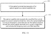
- a sixth aspect of the present disclosure provides a single-fiber bidirectional transmission method.
- the method may include: transmitting a first optical signal from a first optical terminal site to an optical amplifier site; and transmitting the amplified first optical signal from the optical amplifier site to a second optical terminal site.
- the optical amplifier site is disposed in series between the first optical terminal site and the second optical terminal site by using a single fiber, and the optical amplifier site includes the multi-core fiber amplifier according to any one of the second aspect. According to this method, due to the multi-core fiber amplifier in the present disclosure, an optical signal can be transmitted in a first direction by using a single fiber.
- the method may further include: transmitting a second optical signal from the second optical terminal site to the optical amplifier site; and transmitting the amplified second optical signal from the optical amplifier site to the second optical terminal site. In this way, an optical signal can be transmitted in a second direction opposite to the first direction by using a single fiber.
- a multi-core fiber amplifier is a core component for constructing a fiber communications system.
- the multi-core fiber amplifier is suitable for performing gain amplification on light transmitted by the multi-core fiber, to implement long-distance communications transmission of a fiber.
- the multi-core fiber in this specification is a fiber with a plurality of cores in same cladding, and is different from a ribbon fiber (Ribbon fiber).
- the ribbon fiber is a group (or ribbon) of fibers obtained by bonding a plurality of fibers using a special material (for example, glue), and is also referred to as a fiber bundle/cable.
- the multi-core fiber in this specification may be any multi-core fiber including two or more cores, and includes but is not limited to a multi-core fiber including four cores, six cores, seven cores, twelve cores, thirteen cores, nineteen cores, or the like.
- FIG. 1 is a schematic diagram of a structure of a conventional first-type multi-core fiber amplifier 10'.
- a principle of the first-type multi-core fiber amplifier is that a plurality of cores of a multi-core fiber are first demultiplexed into a plurality of single-mode single-core fibers, then pump light and signal light are multiplexed on the single-mode single-core fibers and then multiplexed into the multi-core fiber by using a core multiplexer, and finally, the multiplexed pump light and signal light enter a doped multi-core fiber for amplification.
- the conventional multi-core fiber amplifier 10' may include a multi-core fiber input end 11' and a multi-core fiber output end 12', and the multi-core fiber input end 11' and the multi-core fiber output end 12' are respectively adapted to be coupled to a first multi-core fiber 21' used as an input fiber and a second multi-core fiber 22' used as an output fiber.
- the first multi-core fiber 21' and the second multi-core fiber 22' may be separately adapted to transmit a plurality of signals on which space-division multiplexing is performed.
- the first multi-core fiber 21' is connected to a multi-core fiber fan-out device 13' at thefirst port 11' used as the input end, and the multi-core fiber fan-out device 13' fans out the first multi-core fiber 21' as a plurality of single-core fibers 23'-1, ..., and 23'-n.
- Pump/signal wavelength division multiplexers 14'-1, ..., and 14'-n may be respectively connected to the plurality of single-core fibers 23'-1, ..., and 23'-n, and may be adapted to respectively couple pump light output from pump lasers 18'-1, ..., and 18'-n by using the single-core fibers and signal light in the plurality of single-core fibers 23'-1, ..., and 23'-n together.
- the pump light is used to enable a gain medium (for example, erbium-doped ions) in a subsequent doped multi-core fiber 16' to absorb the pump light, to amplify the signal light.
- a gain medium for example, erbium-doped ions
- the pump/signal wavelength division multiplexers 14'-1, ..., and 14'-n are first coupled to the multi-core fiber fan-in device 15', and then the multi-core fiber fan-in device 15' is coupled to the doped multi-core fiber 16', to implement gain amplification of light.
- the doped multi-core fiber 16' may be coupled to the second port 12' used as the output end by using an optical isolator 17'.
- the optical isolator 17' may cause light to unidirectionally pass through a component, to isolate impact of light reflected by the output end of the amplifier.
- a signal flow of the multi-core fiber amplifier 10' is summarized as follows: Signal light coming from an upstream transmission fiber or transmission device is input from the input end 11' by using the first multi-core fiber 21', and then sequentially passes through the multi-core fiber fan-out device 13', the pump/signal wavelength division multiplexers 14'-1, ..., and 14'-n, and the multi-core fiber fan-in device 15' to enter the doped multi-core fiber 16' for amplification. Then the amplified light passes through the optical isolator 17', and is output from the output end 12' by using the second multi-core fiber 22', to enter and be received by a downstream transmission fiber or transmission device.
- the pump light output from the plurality of pump light sources 18'-1, ..., and 18'-n may pass through the pump/signal wavelength division multiplexers 14'-1, ..., and 14'-n and the multi-core fiber fan-in device 15' to enter the doped multi-core fiber 16' for absorption.
- the first-type multi-core fiber amplifier 10' has the following disadvantage:
- the first-type multi-core fiber amplifier 10' can support only a fiber communications system in which a plurality of beams of signal light are transmitted in a same direction.
- a multi-core fiber needs to be designed, and a distance between cores of the multi-core fiber needs to be sufficiently large to avoid signal coupling crosstalk between the cores. This means that a maximum quantity of cores in a fiber in a case of same dimensions is limited.
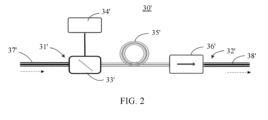
- FIG. 2 is a schematic diagram of a structure of a conventional second-type multi-core fiber amplifier 30'. It should be understood that a principle of the second-type multi-core fiber amplifier 30' is a technical solution in which pump light and a signal are coupled together based on multi-core pump and signal wavelength division multiplexing, and then are multiplexed by using a spatial core multiplexer, to enter a doped fiber for amplification.
- the multi-core fiber amplifier 30' may include a multi-core fiber input end 31' and a multi-core fiber output end 32', and the multi-core fiber input end 31' and the multi-core fiber output end 32' are respectively adapted to be coupled to a first multi-core fiber 37' used as an input fiber and a second multi-core fiber 38' used as an output fiber.
- the first multi-core fiber 37' and the second multi-core fiber 38' are adapted to transmit a plurality of signals on which space-division multiplexing is performed.
- a pump/signal wavelength division multiplexer 33' may be directly connected to the first multi-core fiber 37', and may be adapted to receive pump light output from a pump laser 34' by using a single-core fiber, and couple and multiplex a plurality of beams of signal light in the first multi-core fiber 37' and pump light in the single-core fiber, or demultiplex the pump light and the signal light.
- the multi-core fiber amplifier 30' further includes a doped dual-cladding multi-core fiber 35', and the doped dual-cladding multi-core fiber 35' is coupled to an output end of the pump/signal wavelength division multiplexer 33'.
- Cores of the doped dual-cladding multi-core fiber 35' are covered by inner cladding.
- the cores provide doped ions (for example, erbium-doped ions), and the doped ions can absorb pump light, and then amplify input signal light.
- the inner cladding is configured to couple and transmit multi-mode pump light, and the pump light is absorbed by the doped ions when passing through the cores in the inner cladding.
- a multi-core fiber optical isolator 36' is coupled to the doped dual-cladding multi-core fiber 35', and as a unidirectional pass-through component of light, the multi-core fiber optical isolator 36' may be configured to isolate impact of light reflected by the output end of the amplifier.
- a signal flow of the multi-core fiber amplifier 30' is as follows: Signal light coming from a transmission fiber or a transmission device is input from the input end 31' by using the first multi-core fiber 37', and then passes through the pump/signal wavelength division multiplexer 33' to enter the cores of the doped dual-cladding fiber 35' for amplification. Then the amplified light passes through the optical isolator 36', and is output from the output end 32' by using the second multi-core fiber 38', to enter and be received by a downstream transmission fiber or transmission device.
- the pump light output from the pump laser 34' may be input from a pump input end of the pump/signal wavelength division multiplexer 33', and then may enter the inner cladding of the doped dual-cladding fiber 35' for transmission.
- the pump light can be absorbed by the doped ions.
- the second-type multi-core fiber amplifier 30' has the following disadvantage: Similar to the first-type multi-core fiber amplifier 10', the second-type multi-core fiber amplifier 30' can support only a fiber communications system in which a plurality of beams of signal light are transmitted in a same direction. In addition, similarly, if the transmission device performs reception in a SISO manner, a distance between cores of the multi-core fiber needs to be sufficiently large through control, to avoid inter-core signal coupling crosstalk. This means that a maximum quantity of cores is limited. If the transmission device performs reception in a MIMO manner, a larger MIMO matrix is required, causing disadvantages in component and chip complexity, power consumption, a latency, integration, and other aspects.
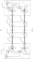
- FIG. 3 is a schematic diagram of application of a conventional multi-core fiber amplifier to a fiber communications system 40'.
- the fiber communications system 40' may include a first optical terminal site 41', a second optical terminal site 42', and at least one optical amplifier site 43' located between the first optical terminal site 41' and the second optical terminal site 42'.
- the optical amplifier site 43' may include either type of optical amplifier (OA) in the first-type multi-core fiber amplifier 10' and the second-type multi-core fiber amplifier 30'.
- OA optical amplifier
- the first optical terminal site 41' and the second optical terminal site 42' each may include a multiplexer (MUX), a demultiplexer (DMUX), a fiber fan-in/fan-out device (FI/FO), an optical transponder unit (OTU), an optical amplifier (OA) such as the first-type multi-core fiber amplifier 10' or the second-type multi-core fiber amplifier 30', and the like.
- MUX multiplexer
- DMUX demultiplexer
- FI/FO fiber fan-in/fan-out device
- OFTU optical transponder unit
- OA optical amplifier
- the first-type multi-core fiber amplifier 10' or the second-type multi-core fiber amplifier 30' can support only co-directional transmission of optical signals. Therefore, to implement bidirectional transmission of the fiber communications system 40', two fibers 45' and 46' used for an uplink and a downlink need to be laid, and respective optical fiber amplifiers are used for the fibers 45' and 46' on the links. In other words, even when a quantity of services actually carried during initial operation is small, two sets of optical amplifier devices are required in east-west directions. As a result, an initial investment of the system increases.
- the present disclosure is intended to provide a multi-core fiber amplifier that can support bidirectional transmission, to avoid using two sets of optical amplifier devices in a fiber communications system, so that construction costs of the fiber communications system can be greatly reduced.
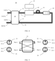
- FIG. 4 is a schematic diagram of a structure of a multi-core fiber amplifier 50 that can support bidirectional transmission according to a first embodiment of the present disclosure.
- the multi-core fiber amplifier 50 may include a first input/output port 51 and a second input/output port 52.
- the first input/output port 51 may be connected to a first multi-core transmission fiber 53 to receive/output signal light
- the second input/output port 52 may be, for example, connected to a second multi-core transmission fiber 54 to output/receive signal light.
- the multi-core fiber amplifier 50 specifically includes a multi-core fiber interleaver 10. It should be understood that bidirectional transmission of the multi-core fiber amplifier 50 becomes possible exactly due to the multi-core fiber interleaver 10.
- the multi-core fiber interleaver 10 may include a first port 11, a second port 12, a third port 13, and a fourth port 14, and the first port 11, the second port 12, the third port 13, and the fourth port 14 may be respectively coupled to a first multi-core fiber 21, a second multi-core fiber 22, a third multi-core fiber 23, and a fourth multi-core fiber 24.
- the first port 21 may be used as the foregoing first input/output port 51
- the fourth port 24 may be used as the foregoing second input/output port 52.
- the first multi-core fiber 21 may be directly used as the foregoing first multi-core transmission fiber 53 of the multi-core fiber amplifier 50
- the fourth multi-core fiber 24 may be directly used as the foregoing second multi-core transmission fiber 54 of the multi-core fiber amplifier 50
- the second port 22 needs to be connected to the third port 23 by using a gain medium 61.
- the gain medium 61 can amplify an optical signal passing through the gain medium 61, to achieve optical output that is of the multi-core fiber amplifier and that is obtained through gain amplification.
- the multi-core fiber interleaver 10 has the following design concept: A first subset of a plurality of cores of the first multi-core fiber 21 coupled to the first port 21 is coupled, through interleaving, to a first subset of a plurality of cores of the second multi-core fiber 21 coupled to the second port 12, and a first subset of a plurality of cores of the fourth multi-core fiber 24 coupled to the fourth port 24 is coupled to a first subset of the third multi-core fiber 23 coupled to the third port 13.
- a second subset of the plurality of cores of the first multi-core fiber 21 is coupled to a second subset of the third multi-core fiber 23 coupled to the third port 13, and a second subset of the plurality of cores of the fourth multi-core fiber 24 coupled to the fourth port 24 is coupled to a second subset of the second multi-core fiber 22 coupled to the second port 12.
- the first subsets of the multi-core fibers include a same quantity (for example, a first quantity) of cores, and the second subsets of the multi-core fibers include a same quantity (for example, a second quantity) of cores. It should be understood that a single-fiber optical fiber amplifier and a subsequent single-fiber fiber transmission system can be implemented by using the multi-core fiber interleaver.
- the multi-core fiber interleaver 10 describes an interleaving structure of the multi-core fiber interleaver 10 in detail only by using two-core fibers, six-core fibers, and seven-core fibers as examples. It should be understood that the multi-core fiber interleaver 10 in the present disclosure is not limited to interleaving examples of the two-core fibers, the six-core fibers, and the seven-core fibers shown below, but is applicable to a multi-core fiber including any quantity of cores, in other words, is applicable to a fiber with two or more cores.
- FIG. 5 is a schematic diagram of interleaving of the multi-core fiber interleaver 10 using two-core fibers as an example.
- the first multi-core fiber 21 is coupled to the first port 11
- the second multi-core fiber 22 is coupled to the second port 12
- the third multi-core fiber 23 is coupled to the third port 13
- the fourth multi-core fiber 24 is coupled to the fourth port 14.
- the first multi-core fiber 21 may include two cores 21-1 and 21-2
- the second multi-core fiber 22 may include two cores 22-1 and 22-2
- the third multi-core fiber 23 may include two cores 23-1 and 23-2
- the fourth multi-core fiber 24 may include two cores 24-1 and 24-2.
- interleaving may be implemented in the following manner:
- the core 21-1 (used as the first subset of the plurality of cores of the first multi-core fiber 21) in the two cores of the first multi-core fiber 21 is coupled to the core 22-1 (used as the first subset of the plurality of cores of the second multi-core fiber 22) of the second multi-core fiber 22, and the core 24-1 (used as the first subset of the plurality of cores of the fourth multi-core fiber 24) of the fourth multi-core fiber 24 is coupled to the core 23-1 (used as the first subset of the plurality of cores of the third multi-core fiber 23) of the third multi-core fiber 23.
- the core 21-2 (used as the second subset of the plurality of cores of the first multi-core fiber 21) of the first multi-core fiber 21 is coupled to the core 23-2 (used as the second subset of the plurality of cores of the third multi-core fiber 23) of the third multi-core fiber 23, and the core 24-2 (used as the second subset of the plurality of cores of the fourth multi-core fiber 24) of the fourth multi-core fiber 24 is coupled to the core 22-2 (used as the second subset of the plurality of cores of the second multi-core fiber 22) of the second multi-core fiber 22.
- the multi-core fiber amplifier 50 in FIG. 4 may be further disposed as follows: The core 22-1 (namely, the first subset of the second multi-core fiber 22) of the second multi-core fiber 22 is connected to the core 23-1 (namely, the first subset of the third multi-core fiber 23) of the third multi-core fiber 23 by using the gain medium 61 outside the multi-core fiber interleaver 10.
- the core 22-2 (namely, the second subset of the second multi-core fiber 22) of the second multi-core fiber 22 is connected to the core 23-2 (namely, the second subset of the third multi-core fiber 23) of the third multi-core fiber 23 by using the gain medium 61 outside the multi-core fiber interleaver 10.
- an optical signal flow may be transmitted along the following first optical transmission path: the core 21-1 located at the first port 11 -> the core 22-1 located at the second port 12 -> the gain medium 61 located outside the interleaver 50 -> the core 23-1 located at the third port 13 -> the core 24-1 located at the fourth port 14.
- an optical signal flow may be transmitted along the following second optical transmission path: the core 24-2 located at the fourth port 14 -> the core 22-2 located at the second port 12 -> the gain medium 61 located outside the interleaver 50 -> the core 23-2 located at the third port 13 -> the core 21-2 located at the first port 11.
- first optical transmission path and the second optical transmission path are opposite when viewed from the outside of the multi-core fiber interleaver and the gain medium as a whole, but optical signals travel along a same path in the gain medium for gain amplification from the perspective of the inside.
- optical signal transmission along the first optical transmission path and the second optical transmission path may be performed at the same time, because a first subset and a second subset limited to a same multi-core fiber do not intersect with each other, and therefore, different cores are used for transmission along the first optical transmission path and the second optical transmission path.
- a corresponding core may be directly fanned out at each port, and cores at different ports may be directly coupled (for example, welded) together.
- a core for example, 21-1 used as the first subset of the plurality of first cores may be fanned out at the first port 11, and may be directly coupled to the core (for example, 22-1) that is used as the first subset of the plurality of second cores and that is fanned out at the second port 12.
- a core (for example, 23-1) used as the first subset of the plurality of third cores may be fanned out at the third port 13, and may be directly coupled to the core (for example, 24-1) that is used as the first subset of the plurality of fourth cores and that is fanned out at the fourth port 14.
- a core (for example, 21-2) used as the second subset of the plurality of first cores may be fanned out at the first port 11, and may be directly coupled to a core (for example, 23-2) that is used as the second subset of the plurality of third cores and that is fanned out at the third port 13.
- a core (for example, 24-2) used as the second subset of the plurality of fourth cores may be fanned out at the fourth port 14, and may be directly coupled to a core (for example, 22-2) that is used as the second subset of the plurality of second cores and that is fanned out at the second port 12.
- This direct coupling manner makes interleaving relatively simple.
- corresponding cores at all ports may be coupled together by using auxiliary interleaving components.
- a core for example, 21-1 used as the first subset of the plurality of first cores may be fanned out at the first port 11, and then may be coupled, by using a first auxiliary interleaving component, to a core (for example, 22-1) that is used as the first subset of the plurality of second cores and that is fanned out at the second port 12.
- a core (for example, 23-1) used as the first subset of the plurality of third cores may be fanned out at the third port 13, and then may be coupled, by using a second auxiliary interleaving component, to a core (for example, 24-1) that is used as the first subset of the plurality of fourth cores and that is fanned out at the fourth port 14.
- a core (for example, 21-2) used as the second subset of the plurality of first cores may be fanned out at the first port 11, and then may be coupled, by using a third auxiliary interleaving component, to a core (for example, 23-2) that is used as the second subset of the plurality of third cores and that is fanned out at the third port 13.
- a core (for example, 24-2) used as the second subset of the plurality of fourth cores may be fanned out at the fourth port 14, and then may be coupled, by using a fourth auxiliary interleaving component, to a core (for example, 22-2) that is used as the second subset of the plurality of second cores and that is fanned out at the second port 12.
- the first auxiliary interleaving component, the second auxiliary interleaving component, the third auxiliary interleaving component, and the fourth auxiliary interleaving component may be selected from a group including a single-core fiber, a spatial waveguide chip, and a spatial optical path structure.
- the first auxiliary interleaving component, the second auxiliary interleaving component, the third auxiliary interleaving component, and the fourth auxiliary interleaving component are used to provide a candidate interleaving solution of cores at a plurality of ports, so that interleaving can be implemented under different spatial or ambient conditions.
- the first port 11, the second port 12, the third port 13, and the fourth port 14 of the interleaver 10 may be respectively coupled to a first port, a second port, a third port, and a fourth port of the spatial waveguide chip, and then corresponding cores at the ports are interleaved by using a waveguide structure on the spatial waveguide chip, so that a core interleaving operation may be simplified.
- the spatial optical path structure may include a fiber collimator and a reflector.
- a first fiber collimator, a second fiber collimator, a third fiber collimator, and a fourth fiber collimator may be respectively disposed at the first port 11, the second port 12, the third port 13, and the fourth port 14, and then light coupled out from a core collimator of a port is reflected to a fiber collimator of another corresponding port by using the reflector, so that the light enters a core at the another port, thereby implementing core interleaving.
- Using the spatial optical path structure to implement core interleaving can expand an application scenario of core interleaving and improve freedom of a core interleaving operation.
- core interleaving of ports may be alternatively implemented through any combination of directly coupling cores at ports, using the single-core fiber, using the spatial waveguide chip, and using the spatial optical path structure. It should be understood that in this way, freedom of core interleaving can be further improved.
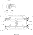
- FIG. 6a is a schematic diagram of interleaving of a multi-core fiber interleaver using six-core fibers as another example
- FIG. 6b is a schematic diagram illustrating, in a core fan-out manner, interleaving of the multi-core fiber interleaver shown in FIG. 6a .
- the first multi-core fiber 21 coupled to the first port 11 includes six cores 21-1, 21-2, 21-3, 21-4, 21-5, and 21-6
- the second multi-core fiber 22 coupled to the second port 12 includes six cores 22-1, 22-2, 22-3, 22-4, 22-5, and 22-6
- the third multi-core fiber 23 coupled to the third port 13 includes six cores 23-1, 23-2, 23-3, 23-4, 23-5, and 23-6
- the fourth multi-core fiber 24 coupled to the fourth port 14 includes three cores 24-1, 24-2, 24-3, 24-4, 24-5, and 24-6.
- interleaving of the six-core fibers may be implemented, for example, in the following manner: Three cores (for example, the cores 21-1, 21-3, and 21-5) in the six cores of the first multi-core fiber 21 are used as a first subset, and the first subset is coupled to a first subset (for example, the cores 22-1, 22-3, and 22-5) of the six cores of the second multi-core fiber 21.
- Three cores (for example, the cores 24-1, 24-3, and 24-5) in the six cores of the fourth multi-core fiber 24 are used as a first subset, and the first subset is coupled to a first subset (for example, the cores 23-1, 23-3, and 23-5) in the six cores of the third multi-core fiber 23.
- the other three cores (for example, the cores 21-2, 21-4, and 21-6) in the six cores of the first multi-core fiber 21 are used as a second subset, and the second subset is coupled to a second subset (for example, the cores 23-2, 23-4, and 23-6) of the third multi-core fiber 23.
- a second subset (for example, the cores 24-2, 24-4, and 24-6) of the six cores of the fourth multi-core fiber 24 is coupled to a second subset (for example, the cores 22-2, 22-4, and 22-6) of the second multi-core fiber 22.
- the multi-core fiber amplifier 50 in FIG. 4 may be further disposed as follows: The first subset (for example, the cores 22-1, 22-3, and 22-5) of the second multi-core fiber 21 is connected to the first subset (for example, the cores 23-1, 23-3, and 23-5) of the third multi-core fiber 23 by using the gain medium 61 outside the multi-core fiber interleaver 10, and the second subset (for example, the cores 22-2, 22-4, and 22-6) of the second multi-core fiber 21 is connected to the second subset (for example, the cores 23-2, 23-4, and 23-6) of the third multi-core fiber 23 by using the gain medium 61 outside the multi-core fiber interleaver 10.
- an optical signal flow may be transmitted along the following first optical transmission path: the cores 22-1, 22-3, and 22-5 located at the first port 11 -> the cores 22-1, 22-3, and 22-5 located at the second port 12 -> the gain medium 61 located outside the interleaver 50 -> the cores 23-1, 23-3, and 23-5 located at the third port 13 -> the cores 24-1, 23-4, and 23-6 located at the fourth port 14.
- an optical signal flow may be transmitted along the following second optical transmission path: the cores 24-2, 24-4, and 24-6 located at the fourth port 14 -> the cores 22-2, 22-4, and 22-6 located at the second port 12 -> the gain medium 61 located outside the interleaver 50 -> the cores 23-2, 23-4, and 23-6 located at the third port 13 -> the cores 21-2, 21-4, and 21-6 located at the first port 11.
- first optical transmission path and the second optical transmission path are opposite, and optical signals undergo gain amplification performed by using the gain medium.
- optical signal transmission along the first optical transmission path and the second optical transmission path may be performed at the same time, because a first subset and a second subset limited to a same multi-core fiber do not intersect with each other, and therefore, different cores are used for the first optical transmission path and the second optical transmission path.
- a corresponding core may be directly fanned out at each port, and cores at different ports may be directly coupled (for example, welded) together.
- the cores 21-1, 21-3, and 21-5 used as the first subset of the plurality of first cores may be fanned out at the first port 11, and may be directly coupled to the cores 22-1, 22-3, and 22-5 that are used as the first subset of the plurality of second cores and that are fanned out at the second port 12.
- the cores 23-1, 23-3, and 23-5 used as the first subset of the plurality of third cores may be fanned out at the third port 13, and may be directly coupled to the cores 24-1, 24-3, and 24-5 that are used as the first subset of the plurality of fourth cores and that are fanned out at the fourth port 14.
- the cores 21-2, 21-4, and 21-6 used as the second subset of the plurality of first cores may be fanned out at the first port 11, and may be directly coupled to the cores 23-2, 23-4, and 23-6 that are used as the second subset of the plurality of third cores and that are fanned out at the third port 13.
- the cores 24-2, 24-4, and 24-6 used as the second subset of the plurality of fourth cores may be fanned out at the fourth port 14, and may be directly coupled to the cores 22-2, 22-4, and 22-6 that are used as the second subset of the plurality of second cores and that are fanned out at the second port 12.
- This direct coupling manner makes interleaving relatively simple.
- corresponding cores at all ports may be coupled together by using auxiliary interleaving components.
- the cores 21-1, 21-3, and 21-5 used as the first subset of the plurality of first cores may be fanned out at the first port 11, and then may be coupled, by using a first auxiliary interleaving component, to the cores 22-1, 22-3, and 22-5 that are used as the first subset of the plurality of second cores and that are fanned out at the second port 12.
- the cores 23-1, 23-3, and 23-5 used as the first subset of the plurality of third cores may be fanned out at the third port 13, and then may be coupled, by using a second auxiliary interleaving component, to the cores 24-1, 24-3, and 24-5 that are used as the first subset of the plurality of fourth cores and that are fanned out at the fourth port 14.
- the cores 21-2, 21-4, and 21-6 used as the second subset of the plurality of first cores may be fanned out at the first port 11, and then may be coupled, by using a third auxiliary interleaving component, to the cores 23-2, 23-4, and 23-6 that are used as the second subset of the plurality of third cores and that are fanned out at the third port 13.
- the cores 24-2, 24-4, and 24-6 used as the second subset of the plurality of fourth cores may be fanned out at the fourth port 14, and then may be coupled, by using a fourth auxiliary interleaving component, to the cores 22-2, 22-4, and 22-6 that are used as the second subset of the plurality of second cores and that are fanned out at the second port 12.
- the first auxiliary interleaving component, the second auxiliary interleaving component, the third auxiliary interleaving component, and the fourth auxiliary interleaving component may be selected from a group including a single-core fiber, a spatial waveguide chip, and a spatial optical path structure.
- the spatial waveguide chip and the spatial optical path structure may be connected in a coupling manner similar to that described above for the two-core fibers.
- the first auxiliary interleaving component, the second auxiliary interleaving component, the third auxiliary interleaving component, and the fourth auxiliary interleaving component are used to provide a candidate interleaving solution of cores at a plurality of ports, so that interleaving can be implemented under different spatial or ambient conditions.
- core interleaving of ports may be alternatively implemented through any combination of directly coupling cores at ports, using the single-core fiber, using the spatial waveguide chip, and using the spatial optical path structure. It should be understood that in this way, freedom of core interleaving can be further improved.
- a quantity (referred to as a first quantity, for example) of cores included in a first subset and a quantity (referred to as a second quantity, for example) of cores included in a second subset of a same multi-core fiber are the same, that is, the first subset and the second subset each include one core or three cores, and a sum of the quantities of cores included in the first subset and the second subset is equal to a total quantity of cores included in the same core, that is, 2 or 6.
- the two-core fibers, the six-core fibers, and selected quantities of cores included in the first subset and the second subset are merely examples, and do not constitute any limitation on the scope of the present disclosure.
- the total quantity of cores included in the multi-core fiber and a quantity of cores included in each of the first subset and the second subset may be adjusted or changed based on an application requirement.
- a sum of a quantity of cores in a first subset and a quantity of cores in a second subset of a same multi-core fiber may be less than or equal to a total quantity of cores included in the same multi-core fiber.
- a quantity (for example, a first quantity) of cores included in a first subset may be equal or unequal to (for example, greater than or less than) a quantity (for example, a second quantity) of cores in a second subset.
- the quantity of cores included in the first subset may be 4, and the quantity of cores included in the second subset may be 2.
- the quantity of cores included in the first subset may be 3, the quantity of cores included in the second subset may be 2, and a sum of the quantities may be less than a total quantity 6 of cores. It should be understood that the quantities of cores in the first subset and the second subset are selected in the foregoing manner, so that freedom of fiber interleaving can be further improved, and optical communications capacity requirements in different directions can be met.
- a same multi-core fiber may further include a third subset in addition to a first subset and a second subset, and a core included in the third subset may be used as an auxiliary communications channel.
- FIG. 7 is a schematic diagram illustrating, in a core fan-out manner, interleaving of a variant example of the multi-core fiber interleaver shown in FIG. 6b .
- each of the first multi-core fiber 21 and the fourth multi-core fiber 24 respectively coupled to the first port 11 and the fourth port 14 includes seven cores
- each of the second multi-core fiber 22 and the third multi-core fiber 23 respectively coupled to the second port 12 and the third port 13 includes six cores.
- each of the first multi-core fiber 21, the second multi-core fiber 22, the third multi-core fiber 23, and the fourth multi-core fiber 24 may be interleaved in a manner the same as that shown in FIG. 6a and FIG. 6b , and details are not described herein again.
- the seventh core 21-7 of the first multi-core fiber 21 and the seventh core of the fourth multi-core fiber 24 may be respectively coupled out from a fifth port 15 and a sixth port 16 of the multi-core interleaver 10 as third subsets.
- the seventh core 21-7 of the first multi-core fiber 21 and the seventh core of the fourth multi-core fiber 24 may be coupled out directly or by using an auxiliary interleaving component.
- the fifth port 15 and the sixth port 16 of the multi-core interleaver 10 may be used as a third port 53 and a fourth port 54 (refer to FIG. 9 ) of the optical fiber amplifier 50.
- the third subsets or the fifth port 15 and the sixth port 16 may be used as auxiliary communications channels of multi-core fibers.
- a core in the third subset may be used to transmit an auxiliary control signal, to control an upstream/a downstream network element such as an upstream/a downstream receiver (for example, optical transponder unit).
- the third subsets or the fifth port 15 and the sixth port 16 may be alternatively used as detection channels for multi-core fiber faults.
- a core in the third subset may be used as a sounding channel of an OTDR for detecting an optical signal, to detect a fault point of a multi-core fiber.
- the third subset may also be applied to a multi-core fiber (for example, a three-core fiber or a six-core fiber) including another quantity of cores.
- the first multi-core fiber 21 and the fourth multi-core fiber 24 may include cores in the third subsets, but also the second multi-core fiber 22 and the third multi-core fiber 23 may include cores in third subsets used as auxiliary communications channels for control signals or fault detection.
- the third subset may include more than one core, and a quantity of cores in the third subset may be selected based on an actual requirement.
- the multi-core fiber interleaver in the present disclosure may be applied to any multi-core fiber with at least two cores, and total quantities of cores included in the first multi-core fiber, the second multi-core fiber, the third multi-core fiber, and the fourth multi-core fiber may be different, provided that the first subsets include a same quantity (that is, the first quantity) of cores, and the second subsets include a same quantity (that is, the second quantity) of cores.
- a first subset and a second subset limited to a same multi-core fiber do not intersect with each other. Therefore, different cores are used by the multi-core fiber sensor to perform bidirectional transmission, so that a design of a communications circuit is simplified. However, this is not mandatory. In some other embodiments, it is possible that a first subset and a second subset limited to a same multi-core fiber intersect with each other. This means that a core in the intersection is used as both a core for an uplink and a core for a downlink. Although this intersection design makes the design of the communications circuit complex, the design may be applied to some special scenarios in which a quantity of cores is limited.
- cores in a first subset or cores in a second subset of a same multi-core fiber are not adjacent to each other. This may increase a distance between the cores in the first subset or the second subset, so that crosstalk of optical signals in a same direction is reduced.
- cores in a first subset and cores in a second subset of a same multi-core fiber are located at alternate positions. In this way, selection of the first subset and the second subset can be simple, and a distance between cores in a first subset or a second subset of a same multi-core fiber can also be ensured, so that crosstalk of optical signals in a same direction is reduced.
- the gain medium 61 is disposed between the second port 12 and the third port 13 to amplify an optical signal passing through the gain medium 61, so that optical output that is of the multi-core fiber amplifier and that is obtained through gain amplification is achieved.
- the gain medium may be, for example, rare-earth element ions such as Er, Nd, or Yb.
- the gain medium is used to perform gain amplification on an optical signal output from the second port 22.
- the gain medium 61 may be implemented as a doped multi-core fiber. Rare-earth element ions such as erbium ions may be doped into a multi-core fiber to implement the doped multi-core fiber. A structure and a function of the doped multi-core fiber are well-known in the art, and details are not described herein.
- a pump/signal wavelength division multiplexer 62 may be provided between the gain medium 61 and the second port 22, and the pump/signal wavelength division multiplexer 62 may couple pump light to signal light output by using the second port 22, and then provide the coupled pump light and signal light to the gain medium 61 implemented as a doped multi-core fiber, for example.
- the gain medium 61 may amplify the input signal light by absorbing the pump light.
- the pump light may be provided by a pump laser 63 to the pump/signal wavelength division multiplexer 62 by using a single-core fiber. In this way, the pump light can be provided in a simple manner.
- a first optical isolator 64 may be provided, and the first optical isolator 64 may be disposed between the gain medium 61 and the third port 13, so that an optical signal unidirectionally passes through a component. This prevents reflected light from entering the gain medium (for example, an erbium-doped fiber) to affect key performance indicators such as a gain and a noise figure of the amplifier.
- the gain medium for example, an erbium-doped fiber
- FIG. 4 actually provides a design of a multi-core fiber amplifier with a simplest function. Therefore, a person skilled in the art may make some modifications and variations to the example embodiment of FIG. 4 without departing from the spirit and scope of the present invention.
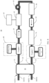
- FIG. 8 is a schematic diagram of a first variation of an example embodiment of the multi-core fiber amplifier shown in FIG. 4 .
- the multi-core fiber amplifier 50 may include another optical functional unit in addition to the multi-core fiber interleaver 10, the first pump/signal wavelength division multiplexer 62, the pump laser 63, and the first optical isolator 64.
- the optical functional unit may include a second optical isolator 65.
- the second optical isolator 65 may be disposed between the gain medium 61 and the second port 12, and in particular, may be disposed between the pump/signal wavelength division multiplexer 61 and the second port 12, so that an optical signal unidirectionally passes through a component. This prevents reverse ASE noise light generated by the gain medium 61 (or an erbium-doped multi-core fiber) from being leaked from an input end.
- the optical functional unit may include a first probe/coupler 68 and/or a second probe/coupler 69.
- the first probe/coupler 68 and the second probe/coupler 69 are used to couple a small portion of optical power of each core of a multi-core fiber for probe array detection.
- the first probe/coupler 68 may be disposed between the second port 12 and the gain medium 61 to detect strength of the optical signal output from the second port 12
- the second probe/coupler 69 may be disposed between the gain medium 61 and the third port 13 to detect strength of the optical signal obtained through gain amplification.
- the first probe/coupler 68 may include a coupler 1 and a probe array 1.
- the coupler 1 is connected to the second multi-core fiber 22 coupled to the second port 12, and the probe array 1 detects, by using the multi-core fiber, signal light coupled out from the coupler 1.
- the second probe/coupler 69 may include a coupler 2 and a probe array 2.
- the coupler 2 is connected to the third multi-core fiber 23 coupled to the third port 13, and the probe array 2 detects, by using the multi-core fiber, signal light that is coupled out from the coupler 2 and that is obtained through gain amplification.
- An unamplified signal is coupled out from the coupler 1, and usually has relatively low power. Therefore, the coupler 1 usually uses a slightly large coupling proportion such as 5%.
- An amplified signal is coupled out from the coupler 2, and usually has relatively high power. Therefore, the coupler 2 usually uses a relatively small coupling proportion such as 1%.
- the optical functional unit may further include a gain flattening filter 70.
- the gain flattening filter 70 is coupled between the third port 13 and the gain medium 61, and in particular, may be coupled between the first optical isolator 64 and the third port 13 to equalize wavelength related gains of the gain medium of the amplifier for signals to be basically consistent.
- the optical functional unit may further include a second pump/signal wavelength division multiplexer 66.
- the second pump/signal wavelength division multiplexer 66 may be disposed between the third port 13 and the gain medium 61, and in particular, may be disposed between the gain flattening filter 70 and/or the second probe/coupler 69 and the gain medium 61 to output, through coupling, residual pump light obtained after absorption of the gain medium (for example, an erbium-doped fiber).
- the gain medium for example, an erbium-doped fiber.
- the first pump/signal wavelength division multiplexer 62 forms a forward pump structure to provide sufficient pump power on an input side of the gain medium (for example, an erbium-doped fiber), to achieve a high inversion and a relatively low noise figure.
- the second pump/signal wavelength division multiplexer 66 is only used to couple out residual pump light. However, the foregoing disposition is not mandatory.
- a pump laser may be connected to the second pump/signal wavelength division multiplexer 66 on an output side of the gain medium (for example, an erbium-doped fiber), to form a reverse pump structure.
- the reverse pump structure has advantages of relatively high pump power conversion efficiency and reducing pump power consumption.
- a group of pump lasers may be added to form a two-way pump structure to balance the noise figure and power conversion efficiency, but costs may increase.
- a fiber and the gain medium (for example, a doped fiber) used in the multi-core fiber amplifier can use a waveguide design to reduce crosstalk between adjacent cores.
- a special refractive index distribution design or a core pitch design is used to reduce crosstalk impact.
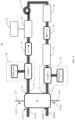
- FIG. 9 is a schematic diagram of a second variation of an example embodiment of the multi-core fiber amplifier shown in FIG. 4 .
- the multi-core fiber amplifier shown in FIG. 9 uses the multi-core fiber interleaver shown in FIG. 7 .
- the multi-core fiber interleaver has six ports, namely, the first port 11, the second port 12, the third port 13, the fourth port 14, the fifth port 15, and a sixth port 17.
- the first port 11 may be used as the first input/output port 51 of the optical fiber amplifier 50
- the second port 12 may be used as the second input/output port 52 of the optical fiber amplifier 50
- the fifth port 15 may be used as a first auxiliary communications port 55 of the optical fiber amplifier 50
- the sixth port 16 may be used as a second auxiliary communications port 56 of the optical fiber amplifier 50.
- the first auxiliary communications port 55 and the second auxiliary communications port 56 may be configured to provide auxiliary communications channels to detect a fiber fault point by using the OTDR and/or provide an optical signal for controlling an upstream/a downstream network element.
- each of the first input/output port 51 and the second input/output port 52 may be used as a signal input port or a signal output port. Therefore, the multi-core fiber amplifier in the present disclosure can implement bidirectional transmission of optical signals.
- the optical signal is amplified by the gain medium 61 of the multi-core fiber amplifier 60, and then coupled out from the first subset of the fourth multi-core fiber 24 coupled to the second input/output port 52, thereby implementing optical transmission of the optical signal from the first input/output port 51 to the second input/output port 52.
- the optical signal is amplified by the gain medium 61 of the multi-core fiber amplifier 60, and then coupled out from the second subset of the first multi-core fiber 21 coupled to the first input/output port 51, thereby implementing optical transmission of the optical signal from the second input/output port 52 to the first input/output port 51.
- the first auxiliary communications port 55 may be configured to receive an optical signal from the third subset of the first multi-core fiber 21 coupled to the first input/output port 51
- the second auxiliary communications port 56 may be configured to receive an optical signal from the third subset of the fourth multi-core fiber 24 coupled to the second input/output port 52.
- the optical signals received by the first auxiliary communications port 55 and the second auxiliary communications port 56 may be used to detect light intensity and/or used as optical signals for controlling an upstream/a downstream network element.
- the multi-core fiber amplifier in the present disclosure has the following advantages over the conventional first-type optical fiber amplifier and second-type optical fiber amplifier:
- the following describes example application of the multi-core fiber amplifier in the present disclosure to a fiber communications system 100 with reference to FIG. 10 .
- At least one optical amplifier site 90 may be disposed between a first optical terminal site 80 and a second optical terminal site 81, and the optical amplifier site 90 may include the multi-core fiber amplifier 50 in the present disclosure.
- the first optical terminal site 80 or the second optical terminal site 81 may include at least one of an optical transponder unit and a multiplexer or a demultiplexer. It should be understood that the example of the first optical terminal site 80 or the second optical terminal site 81 herein does not constitute a limitation.
- the first optical terminal site 80 or the second optical terminal site 81 may alternatively include another optical communications unit, for example, may include the optical fiber amplifier 50 in the present disclosure.
- the multi-core fiber amplifier 50 in the present disclosure is adapted for bidirectional transmission, and therefore the optical amplifier site 90 is also adapted for bidirectional transmission. Because of this bidirectional transmission characteristic, the optical amplifier site 90 in the present disclosure can be disposed in series between the first optical terminal site 80 and the second optical terminal site 81 by using a single fiber.
- the at least one optical amplifier site 90 may include a plurality of optical amplifier sites 90.
- the plurality of optical amplifier sites 90 may also be connected in series by using a single fiber, and then may be coupled between the first optical terminal site 80 and the second optical terminal site 81.
- the fiber communications system 100 in the present disclosure can implement a bidirectional transmission system through deployment by using only a single fiber.
- only a single multi-core fiber amplifier may be disposed for each optical amplifier site 90 in the present disclosure. Therefore, when a transmission capacity is small, the fiber communications system in the present disclosure reduces engineering deployment costs (for example, a quantity of installed devices and a quantity of leased fibers) and operation costs (for example, power consumption).
- bidirectionally transmitted signals are transmitted by using a single fiber in the fiber communications system in the present disclosure, it is ensured that latencies of an uplink and a downlink are consistent, so that a problem of inconsistent bidirectional latencies in the conventional technology is cleverly resolved.
- the multi-core fiber used as a transmission fiber in the present disclosure may be approximately considered as a coupling-free fiber, so that a receiver may not need to use a MIMO receiving technology. Therefore, complexity of the receiver is greatly reduced, and crosstalk costs can be ignored.
- multi-core fiber interleaver the multi-core fiber amplifier, and the single-fiber bidirectional transmission system may be applied to the following multi-core fiber interleaving method, optical amplification method for a multi-core fiber, or single-fiber bidirectional transmission method without conflicting with each other.
- FIG. 11 is a schematic flowchart of a multi-core fiber interleaving method according to an example embodiment of the present disclosure.
- a first subset for example, cores 21-1, 21-3, and 21-5) of a plurality of first cores of a first multi-core fiber 21 is coupled to a first subset (for example, cores 22-1, 22-3, and 22-5) of a plurality of second cores of a second multi-core fiber 22.
- a first subset for example, cores 23-1, 23-3, and 23-5) of a plurality of third cores of a third multi-core fiber 23 is coupled to a first subset (for example, cores 24-1, 24-3, and 24-5) of a plurality of fourth cores of a fourth multi-core fiber 24.
- a second subset for example, cores 21-2, 21-4, and 21-6) of the plurality of first cores is coupled to a second subset (for example, cores 23-2, 23-4, and 23-6) of the plurality of third cores.
- a second subset for example, cores 24-2, 24-4, and 24-6) of the plurality of fourth cores is coupled to a second subset (for example, cores 22-2, 22-4, and 22-6) of the plurality of second cores.
- the first subsets of the multi-core fibers include a same quantity of cores, and the second subsets of the multi-core fibers include a same quantity of cores.
- interleaving can be implemented between the first multi-core fiber 21, the second multi-core fiber 22, the third multi-core fiber 23, and the fourth multi-core fiber 24.
- the foregoing interleaving method may also be associated with a gain medium.
- the first subset for example, the cores 22-1, 22-3, and 22-5) of the plurality of second cores is coupled to the first subset (for example, the cores 23-1, 23-3, and 23-5) of the plurality of third cores by using a gain medium 61.
- the second subset for example, the cores 22-2, 22-4, and 22-6) of the plurality of second cores is coupled to the second subset (for example, the cores 23-2, 23-4, and 23-6) of the plurality of third cores by using the gain medium 61.
- the cores in both the first subset and the second subset can be further associated with the gain medium, so that gain amplification of an input optical signal can be implemented.
- the multi-core fiber interleaving method may be directly used to produce/assemble the foregoing multi-core fiber interleaver, and therefore implement production of a fiber interleaver used as a component or a product.
- the multi-core fiber interleaving method may be directly used to produce/assemble a multi-core fiber amplifier, and therefore implement a multi-core fiber amplifier used as a product, and an operation of packaging the fiber interleaver can be omitted.
- the multi-core fiber interleaving method in the present disclosure may be automatically completed by a machine, or may be manually completed, for example, completed by a worker of a factory that produces the multi-core interleaver.
- FIG. 12 is a schematic flowchart of an optical amplification method applicable to a multi-core fiber according to an example embodiment of the present disclosure.
- a first optical signal is received by using a first subset (for example, cores 21-1, 21-3, and 21-5) of a first multi-core fiber 21.
- a first subset for example, cores 21-1, 21-3, and 21-5
- the first optical signal is transmitted to a first subset (for example, cores 22-1, 22-3, and 22-5) of a second multi-core fiber 22.
- the first optical signal coming from the first subset (for example, the cores 22-1, 22-3, and 22-5) of the second multi-core fiber 22 is transmitted to a first subset (for example, cores 23-1, 23-3, and 23-5) of a third multi-core fiber 23 by using a gain medium 61.
- the amplified first optical signal is transmitted to a first subset (for example, cores 24-1, 24-3, and 24-5) of a fourth multi-core fiber 24.
- the first optical signal is output by using the first subset (for example, the cores 24-1, 24-3, and 24-5) of the fourth multi-core fiber 24.
- the first subsets of the multi-core fibers include a same quantity of cores.
- the foregoing optical amplification method may further include the following operations:
- FIG. 13 is a schematic flowchart of a single-fiber bidirectional transmission method applicable to a multi-core fiber according to an example embodiment of the present disclosure.
- a first optical terminal site 80 transmits a first optical signal to an optical amplifier site 90.
- the optical amplifier site 90 transmits the amplified first optical signal to a second optical terminal site 81.
- the optical amplifier site 90 may be disposed in series between the first optical terminal site 80 and the second optical terminal site 81 by using a single fiber, and includes the foregoing multi-core fiber amplifier 50.
- the single-fiber bidirectional transmission method may further include the following operations: transmitting, by the second optical terminal site 81, a second optical signal to the optical amplifier site 90; and transmitting, by the optical amplifier site 90, the amplified second optical signal to the second optical terminal site 80.
Landscapes
- Physics & Mathematics (AREA)
- Electromagnetism (AREA)
- Engineering & Computer Science (AREA)
- Optics & Photonics (AREA)
- Computer Networks & Wireless Communication (AREA)
- Signal Processing (AREA)
- Plasma & Fusion (AREA)
- General Physics & Mathematics (AREA)
- Lasers (AREA)
- Optical Communication System (AREA)
- Optical Fibers, Optical Fiber Cores, And Optical Fiber Bundles (AREA)
- Optical Couplings Of Light Guides (AREA)
Applications Claiming Priority (2)
| Application Number | Priority Date | Filing Date | Title |
|---|---|---|---|
| CN202010621709.9A CN113872694A (zh) | 2020-06-30 | 2020-06-30 | 多芯光纤交织器、光纤放大器、传输系统以及传输方法 |
| PCT/CN2021/096273 WO2022001518A1 (zh) | 2020-06-30 | 2021-05-27 | 多芯光纤交织器、光纤放大器、传输系统以及传输方法 |
Publications (2)
| Publication Number | Publication Date |
|---|---|
| EP4156552A1 true EP4156552A1 (de) | 2023-03-29 |
| EP4156552A4 EP4156552A4 (de) | 2023-11-22 |
Family
ID=78981890
Family Applications (1)
| Application Number | Title | Priority Date | Filing Date |
|---|---|---|---|
| EP21831947.3A Pending EP4156552A4 (de) | 2020-06-30 | 2021-05-27 | Mehradriger glasfaserverschachteler, glasfaserverstärker, übertragungssystem und übertragungsverfahren |
Country Status (5)
| Country | Link |
|---|---|
| US (1) | US20230122793A1 (de) |
| EP (1) | EP4156552A4 (de) |
| JP (1) | JP7471474B2 (de) |
| CN (1) | CN113872694A (de) |
| WO (1) | WO2022001518A1 (de) |
Families Citing this family (3)
| Publication number | Priority date | Publication date | Assignee | Title |
|---|---|---|---|---|
| JP7529031B2 (ja) * | 2020-09-14 | 2024-08-06 | 日本電気株式会社 | 光ネットワーク、ネットワーク管理装置及びネットワーク管理方法 |
| WO2022244236A1 (ja) * | 2021-05-21 | 2022-11-24 | 日本電信電話株式会社 | 通信経路割当装置、通信経路割当方法、およびプログラム |
| WO2025062579A1 (ja) * | 2023-09-21 | 2025-03-27 | 日本電信電話株式会社 | コア切替装置および光増幅システム |
Family Cites Families (15)
| Publication number | Priority date | Publication date | Assignee | Title |
|---|---|---|---|---|
| JPH05129685A (ja) * | 1991-11-05 | 1993-05-25 | Sumitomo Electric Ind Ltd | 光合分波器及び光フアイバ増幅器 |
| JPH05335673A (ja) * | 1992-05-28 | 1993-12-17 | Hitachi Cable Ltd | 光増幅器 |
| US5740289A (en) * | 1996-12-30 | 1998-04-14 | At&T Corp | Optical arrangement for amplifying WDM signals |
| US6819481B2 (en) * | 2001-06-04 | 2004-11-16 | Lucent Technologies Inc. | Bidirectional wave division multiplex systems |
| JP4211446B2 (ja) * | 2003-03-19 | 2009-01-21 | 日本電気株式会社 | 遠隔励起光増幅モジュール並びにこれを使用した光ファイバ通信用伝送路及び光ファイバ通信システム |
| WO2013157245A1 (ja) * | 2012-04-20 | 2013-10-24 | 日本電気株式会社 | 多重光伝送路、光伝送システムおよび光伝送方法 |
| JP2014116466A (ja) * | 2012-12-10 | 2014-06-26 | Nippon Telegr & Teleph Corp <Ntt> | 光ファイバ増幅器 |
| JP5659341B2 (ja) * | 2013-06-05 | 2015-01-28 | 日本電信電話株式会社 | マルチコア光伝送システム、光増幅及び光増幅用部品 |
| US20150085352A1 (en) * | 2013-09-20 | 2015-03-26 | Alcatel-Lucent Usa Inc. | Optical amplifier for space-division multiplexing |
| US9362708B2 (en) * | 2013-09-20 | 2016-06-07 | Alcatel Lucent | Compact two-stage optical amplifier |
| US9806486B2 (en) * | 2015-03-19 | 2017-10-31 | Ii-Vi Incorporated | Optical amplifier module |
| CN204761439U (zh) * | 2015-06-12 | 2015-11-11 | 上海南明光纤技术有限公司 | 双纤双工结构有源光缆通信架构 |
| CN108292955A (zh) * | 2015-11-26 | 2018-07-17 | 日本电信电话株式会社 | 通信系统以及连接器 |
| CN108292957B (zh) * | 2015-11-26 | 2021-03-26 | 日本电信电话株式会社 | 光放大系统以及光放大方法 |
| CN109104244A (zh) * | 2018-09-11 | 2018-12-28 | 北京邮电大学 | 一种多芯光纤通信系统以及一种多芯光纤通信方法 |
-
2020
- 2020-06-30 CN CN202010621709.9A patent/CN113872694A/zh active Pending
-
2021
- 2021-05-27 JP JP2022581324A patent/JP7471474B2/ja active Active
- 2021-05-27 EP EP21831947.3A patent/EP4156552A4/de active Pending
- 2021-05-27 WO PCT/CN2021/096273 patent/WO2022001518A1/zh not_active Ceased
-
2022
- 2022-12-21 US US18/069,846 patent/US20230122793A1/en active Pending
Also Published As
| Publication number | Publication date |
|---|---|
| JP7471474B2 (ja) | 2024-04-19 |
| CN113872694A (zh) | 2021-12-31 |
| JP2023532109A (ja) | 2023-07-26 |
| US20230122793A1 (en) | 2023-04-20 |
| WO2022001518A1 (zh) | 2022-01-06 |
| EP4156552A4 (de) | 2023-11-22 |
Similar Documents
| Publication | Publication Date | Title |
|---|---|---|
| US20230122793A1 (en) | Multi-core fiber interleaver, optical fiber amplifier, transmission system, and transmission method | |
| CN110945421B (zh) | 光放大中继系统和光放大器 | |
| US12034269B2 (en) | Light amplifying relay system | |
| CN109802289A (zh) | 一种低差模增益少模掺铒光纤放大器 | |
| Sakamoto et al. | Characteristics of randomly coupled 12-core erbium-doped fiber amplifier | |
| US6529656B2 (en) | Bi-Directional add/drop multiplexer and bidirectional add/drop amplifier module for wavelength interleaved bidirectional networks | |
| JP2001333015A (ja) | 光合波装置および光合波方法 | |
| CA2325580C (en) | Wdm transmission repeater, wdm transmission system and wdm transmission method | |
| JP5659341B2 (ja) | マルチコア光伝送システム、光増幅及び光増幅用部品 | |
| US7734180B2 (en) | Single fibre bidirectional optical transmission system and single fibre bidirectional optical amplifier | |
| CN100525146C (zh) | 使用远程泵激的光纤通信系统 | |
| JP4798997B2 (ja) | 単一のポンプ装置から異なる一対のファイバに位置する光ファイバへポンプ・エネルギを分配する方法および装置 | |
| US6832017B2 (en) | Bidirectional add/drop multiplexer and bidirectional add/drop amplifier module for band-split bidirectional networks | |
| US20010038477A1 (en) | High-isolation wavelength managing module for bi-directional wavelength division multiplexing optical communication system | |
| RU2273957C2 (ru) | Способ выравнивания мощности в системе плотного уплотнения каналов связи с разделением по длине волны | |
| US20020093708A1 (en) | Method and apparatus for the frequency band-dependent distribution and influencing of data signals of a WDM system | |
| JP2002158384A (ja) | 増幅用光ファイバ、光ファイバ増幅器、光送信器及び光通信システム | |
| US6697575B1 (en) | System and method for increasing capacity of long-haul optical transmission systems | |
| WO2021065308A1 (ja) | 光中継器及び光通信システム | |
| EP0989638A1 (de) | Vorrichtung zum Pumpen eines optischen Faserverstärkers | |
| JP4607892B2 (ja) | 光ネックワーク、及び光ネックワークの増幅器ノード | |
| JP3593994B2 (ja) | 双方向伝送用利得等化器 | |
| JP2635188B2 (ja) | 光アクティブモジュール | |
| Chen et al. | Hybrid transmissive optical star couplers with gain using fiber amplifiers | |
| Wada et al. | Coupled 2-LP 6-core EDFA with 125 μm cladding diameter |
Legal Events
| Date | Code | Title | Description |
|---|---|---|---|
| STAA | Information on the status of an ep patent application or granted ep patent |
Free format text: STATUS: THE INTERNATIONAL PUBLICATION HAS BEEN MADE |
|
| PUAI | Public reference made under article 153(3) epc to a published international application that has entered the european phase |
Free format text: ORIGINAL CODE: 0009012 |
|
| STAA | Information on the status of an ep patent application or granted ep patent |
Free format text: STATUS: REQUEST FOR EXAMINATION WAS MADE |
|
| 17P | Request for examination filed |
Effective date: 20221222 |
|
| AK | Designated contracting states |
Kind code of ref document: A1 Designated state(s): AL AT BE BG CH CY CZ DE DK EE ES FI FR GB GR HR HU IE IS IT LI LT LU LV MC MK MT NL NO PL PT RO RS SE SI SK SM TR |
|
| DAV | Request for validation of the european patent (deleted) | ||
| DAX | Request for extension of the european patent (deleted) | ||
| A4 | Supplementary search report drawn up and despatched |
Effective date: 20231023 |
|
| RIC1 | Information provided on ipc code assigned before grant |
Ipc: H04B 10/297 20130101ALI20231017BHEP Ipc: H01S 3/067 20060101ALI20231017BHEP Ipc: H04J 14/04 20060101ALI20231017BHEP Ipc: H04B 10/25 20130101AFI20231017BHEP |