EP4163071A1 - Ringbohrkrone mit einer verbesserten bohrkernentfernung - Google Patents
Ringbohrkrone mit einer verbesserten bohrkernentfernung Download PDFInfo
- Publication number
- EP4163071A1 EP4163071A1 EP21201907.9A EP21201907A EP4163071A1 EP 4163071 A1 EP4163071 A1 EP 4163071A1 EP 21201907 A EP21201907 A EP 21201907A EP 4163071 A1 EP4163071 A1 EP 4163071A1
- Authority
- EP
- European Patent Office
- Prior art keywords
- drill
- ring
- minimum value
- max
- drill bit
- Prior art date
- Legal status (The legal status is an assumption and is not a legal conclusion. Google has not performed a legal analysis and makes no representation as to the accuracy of the status listed.)
- Withdrawn
Links
- 238000007620 mathematical function Methods 0.000 claims description 4
- 125000006413 ring segment Chemical group 0.000 description 70
- 238000005553 drilling Methods 0.000 description 16
- 102100037010 Fidgetin Human genes 0.000 description 4
- 101000878296 Homo sapiens Fidgetin Proteins 0.000 description 4
- 238000004519 manufacturing process Methods 0.000 description 3
- 229910003460 diamond Inorganic materials 0.000 description 2
- 239000010432 diamond Substances 0.000 description 2
- 230000015572 biosynthetic process Effects 0.000 description 1
- 230000007423 decrease Effects 0.000 description 1
- 230000001419 dependent effect Effects 0.000 description 1
- 238000011161 development Methods 0.000 description 1
- 230000018109 developmental process Effects 0.000 description 1
- 239000012634 fragment Substances 0.000 description 1
- 238000012986 modification Methods 0.000 description 1
- 230000004048 modification Effects 0.000 description 1
- 239000002245 particle Substances 0.000 description 1
- 239000000758 substrate Substances 0.000 description 1
Images


Classifications
-
- B—PERFORMING OPERATIONS; TRANSPORTING
- B28—WORKING CEMENT, CLAY, OR STONE
- B28D—WORKING STONE OR STONE-LIKE MATERIALS
- B28D1/00—Working stone or stone-like materials, e.g. brick, concrete or glass, not provided for elsewhere; Machines, devices, tools therefor
- B28D1/02—Working stone or stone-like materials, e.g. brick, concrete or glass, not provided for elsewhere; Machines, devices, tools therefor by sawing
- B28D1/04—Working stone or stone-like materials, e.g. brick, concrete or glass, not provided for elsewhere; Machines, devices, tools therefor by sawing with circular or cylindrical saw-blades or saw-discs
- B28D1/041—Working stone or stone-like materials, e.g. brick, concrete or glass, not provided for elsewhere; Machines, devices, tools therefor by sawing with circular or cylindrical saw-blades or saw-discs with cylinder saws, e.g. trepanning; saw cylinders, e.g. having their cutting rim equipped with abrasive particles
-
- B—PERFORMING OPERATIONS; TRANSPORTING
- B23—MACHINE TOOLS; METAL-WORKING NOT OTHERWISE PROVIDED FOR
- B23B—TURNING; BORING
- B23B51/00—Tools for drilling machines
- B23B51/04—Drills for trepanning
- B23B51/0473—Details about the connection between the driven shaft and the tubular cutting part; Arbors
Definitions
- the present invention relates to a ring drill bit according to the preamble of claim 1.
- Ring drill bits are mainly used for drill bits with small diameters of up to approx. 50 mm and segmented drill bits for drill bits with diameters from 35 mm. Due to a larger connection surface of the ring segment to the drill shaft, ring drill bits have a higher mechanical stability than segmented drill bits during drilling operation, whereas the advantages of set diamond particles can be used when constructing the drill segments for segmented drill bits.
- Known ring drill bits comprise a drill shank with a shank end and a ring segment which is fastened with an underside to an end face of the drill shank; the ring core bit can be attached via the shank in the tool holder of a core drill.
- the drill shaft has a cylinder with a longitudinal axis and the ring segment has an inner lateral surface and an outer lateral surface, the inner lateral surface being cylindrical and having a constant inner distance from the longitudinal axis in a plane perpendicular to the longitudinal axis.
- a drill core is created inside the drill bit, which has to be removed from the drill bit after drilling, which can lead to problems and the drill core gets stuck inside.
- Particular problems are caused by fragments that break out of the drill core and can get stuck between the drill bit and the drill core.
- the object of the present invention is to develop a ring drill bit with a ring segment in which the risk of jammed drill cores is reduced.
- the removal of a jammed drill core should be simplified.
- the ring bit is characterized in that the inner distance in the circumferential direction has a first minimum value, a second minimum value, a first maximum value and a second maximum value, the first maximum value being arranged in the circumferential direction between the first minimum value and the second minimum value and the second maximum value is located between the second minimum value and the first minimum value in the circumferential direction.
- the inner spacing of the inner lateral surface varies over the circumference of the ring segment between the minimum and maximum values.
- the smallest inner distance to the longitudinal axis determines the core diameter of the drill core, which corresponds to twice the smallest inner distance.
- the distribution of the first and second minimum values and the first and second maximum values over the circumference of the ring segment makes it possible to produce ring segments in which a gap forms between the ring segment and the drill core over a partial circumference of the ring segment during drilling operation, which poses the risk of jammed drill cores reduced and can facilitate the removal of a stuck core.
- the ring segment should have a maximum of two minimum values with the same smallest inner distance.
- the first minimum value and the second minimum value preferably match.
- a ring segment in which the first minimum value and the second minimum value of the inner distance match within the scope of manufacturing accuracy achieves uniform removal during drilling and can reduce vibrations of the ring drill bit.
- the first minimum value and the second minimum value are preferably offset from one another by 180° in the circumferential direction. With an offset of approximately 180°, the first and second minimum values are opposite one another in the circumferential direction and lead to a mirror-symmetrical structure of the inner lateral surface, particularly in the case of ring segments with matching first and second minimum values. Due to the symmetrical structure Vibrations of the ring drill bit can be reduced during drilling and the smooth running of the ring drill bit can be improved.
- the inner distance over the circumference of the ring segment describes a mathematical function that is strictly monotonous in the area of the first minimum value and the second minimum value.
- the contact surface of the ring segment to the drill core is reduced and the friction between the ring segment and the drill core is reduced by a strictly monotonous progression of the inner distance in the area of the minimum values.
- the areas where the core can get stuck are further reduced.
- the first maximum value and the second maximum value preferably match.
- a ring segment in which the first maximum value and the second maximum value of the inner distance match within the scope of manufacturing accuracy achieves uniform removal during drilling and can reduce vibrations of the ring drill bit.
- the first maximum value and the second maximum value are preferably offset from one another by 180° in the circumferential direction. With an offset of 180°, the first and second maximum values are opposite to one another in the circumferential direction.
- This distribution of the first and second maximum values over the circumference of the ring segment makes it possible to produce ring segments in which a gap forms between the ring segment and the drill core over a partial circumference during drilling operation, with the maximum gap being in the area of the maximum internal distances.
- a stuck core can be moved in the ring segment by the operator, facilitating the removal of a stuck core.
- the inner lateral surface of the ring segment in the plane perpendicular to the longitudinal axis of the drill shaft has an elliptical shape with a short semi-axis and a long semi-axis, with the first and second minimum values forming the short semi-axis and the first and second maximum values forming the long semi-axis.
- the elliptical shape of the inner lateral surface enables a strictly monotonous progression of the inner distance in the area of the minimum values.
- the inner lateral surface of the ring segment is designed as a cylinder with a base that is different from a circular shape.
- the design of the inner lateral surface as a cylinder has the advantage that the removal properties of the ring segment are constant over the height.
- the base area particularly preferably has an elliptical shape; the elliptical shape is particularly suitable as a non-circular base.
- the inner lateral surface of the ring segment is designed as an inner cone which tapers in the direction of an upper side opposite the underside of the ring segment.
- a ring segment whose inner lateral surface is designed as an inner cone with a non-circular base has the advantage that the contact surface is further reduced and the friction between the ring segment and the drill core is reduced.
- the fact that the inner cone tapers in the direction of the upper side of the ring segment can make it easier to remove a stuck drill core.
- the risk of the drill core jamming in the ring segment is greatest in the area of the smallest inner distance. Since the top of the ring segment is accessible to the operator, the operator can remove the stuck core.
- the inner cone preferably has a base that is different from a circular shape.
- the base area particularly preferably has an elliptical shape; the elliptical shape is particularly suitable as a non-circular base.
- FIG. 1 shows a ring drill bit 10 which has a drill shank 11 with a shank end 12 and a closed ring segment 13 .
- the ring drill bit 10 is fastened via the shank 12 in the tool holder of a core drilling device and is driven in drilling operation by the core drilling device about an axis of rotation which runs coaxially to the longitudinal axis 14 of the drill shaft 11 .
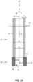
- FIGN. 2A , B show a drill bit 20 according to the invention, which has a drill shank 21 and a ring segment 22 . while showing FIG. 2A the drill shaft 21 and the ring segment 22 in a longitudinal section parallel to the longitudinal axis 23 of the drill shaft 21 and FIG. 2C the ring segment 22 in a cross section perpendicular to the longitudinal axis 23 of the drill shaft 21.
- the drill shank 21 comprises a cylinder 24 which has an outer diameter d A , an inner diameter di and a shank width b in a plane 25 perpendicular to the cylinder axis which defines the longitudinal axis 23 of the drill shank 21 .
- the inside diameter d I , the outside diameter d A and the shank width b are constant both in a circumferential direction ⁇ and in a height direction h .
- the inner diameter, the outer diameter and/or the shank width can vary in the circumferential direction ⁇ and/or the height direction h.
- the ring segment 22 comprises an inner surface 26 , an outer surface 27 , a bottom 28 and a top 29 , the bottom 28 of the ring segment 22 being attached to a front surface 31 of the drill shaft 21 .
- the inner lateral surface 26 is designed as a cylinder 32 with a base that is different from a circular shape.
- the formation of the inner lateral surface 26 as a cylinder has the advantage that the removal properties of the ring segment 22 are constant over the height.
- the inner lateral surface 26 has an internal spacing B( ⁇ , h) from the longitudinal axis 23 .
- the inner distance B( ⁇ , h) defines a mathematical function that describes the course of the inner distance over the circumference and the height of the ring segment 22 .
- the inner distance B( ⁇ , h) varies in the circumferential direction ⁇ over the circumference of the ring segment 22 between two minimum values and two maximum values; in the height direction h the inner distance B( ⁇ , h) is constant.
- the inner distance B( ⁇ , h) has a first minimum value B min,1 , a first maximum value B max , 1 , a second minimum value B min,2 and a second maximum value B max,2 .
- the first minimum value B min,1 and the second minimum value B min,2 are offset from one another by approx. 180° in the circumferential direction ⁇ , and the first maximum value B max,1 and the second maximum value B max,2 are also offset by approx 180° offset to each other.
- the minimum values B min,1 , B min,2 and the maximum values B max,1 , B max,2 are opposite one another in the circumferential direction ⁇ and lead to a mirror-symmetrical structure of the inner lateral surface 26
- the symmetrical structure can reduce vibrations of the drill bit 20 during drilling and the smooth running of the drill bit 20 can be improved.
- FIG. 2 B shows the ring segment 22 and a drill core 33, which the drill bit 20 produces during drilling, in a cross section perpendicular to the longitudinal axis 23 of the drill shaft 21.
- the smallest inner distance of the inner lateral surface 26 to the longitudinal axis 23 determines the core diameter, which corresponds to twice the smallest inner distance.
- the distribution of the first and second minimum values B min,1 , B min,2 and the first and second maximum values B max,1 , B max,2 over the circumference of the ring segment 22 enables the production of ring segments in which during drilling operation between the Ring segment 22 and the drill core 33 forms a gap which reduces the risk of jammed drill cores and facilitates the removal of a jammed drill core.
- the inner lateral surface 26 has an elliptical shape in the plane 25 perpendicular to the longitudinal axis 23 with a short semi-axis a 1 and a long semi-axis a 2 , the first and second minimum values B min,1 , B min,2 being the short semi-axis a 1 and the first and second maximum values B max,1 , B max,2 form the long semi-axis a 2 .
- the elliptical shape is particularly suitable as a non-circular base area of the cylinder 32.
- FIGN. 3A , B show a second embodiment of a ring segment 42 for the drill bit 20 in a longitudinal section parallel to the longitudinal axis 23 of the drill shaft 21 ( FIG. 3A ) and in a cross section perpendicular to the longitudinal axis 23 of the drill shaft 21 ( FIG. 3B ).
- the ring segment 42 differs from the ring segment 22 in the design of the inner lateral surface.
- the ring segment 42 comprises an inner lateral surface 46, an outer lateral surface 47, an underside 48 and an upper side 49, the ring segment 42 being fastened with the underside 48 to the end face 31 of the drill shaft 21.
- the inner lateral surface 46 is designed as an inner cone 52 with a base that is different from a circular shape, with the inner cone 52 tapering in the direction of the upper side 49 of the ring segment 42 .
- the design of the inner lateral surface 46 as an inner cone 52 with a non-circular base has the advantage that the contact surface between the ring segment 42 and the drill core 33 can be reduced.
- the tapering of the inner cone in the direction of the upper side 49 of the ring segment 42 can facilitate the removal of a jammed drill core.
- the risk of the drill core jamming in the ring segment 42 is greatest in the area of the smallest inner distance. Since the top 49 of the ring segment 42 is accessible to the operator, the operator can loosen and remove the stuck core.
- the inner lateral surface 46 of the ring segment 42 has an inner distance B ( ⁇ , h) to the longitudinal axis 23 in the plane 25 perpendicular to the longitudinal axis 23 .
- the inner distance B( ⁇ , h) defines a mathematical function that describes the course of the inner distance over the circumference and the height of the ring segment 42 .
- the inner distance B( ⁇ , h) varies in the circumferential direction ⁇ over the circumference of the ring segment 42 between two minimum values and two maximum values; the inner distance B( ⁇ , h) varies in the height direction h and decreases in the direction of the upper side 49 of the ring segment 42 .
- the inner distance B( ⁇ , h) has a first minimum value B min,1 , a first maximum value B max ,1 , a second minimum value B min,2 and a second maximum value B max,2 .
- the first minimum value B min,1 and the second minimum value B min,2 are offset from one another by approx. 180° in the circumferential direction ⁇ , and the first maximum value B max,1 and the second maximum value B max,2 are also offset by approx 180° offset to each other.
- the minimum values B min,1 , B min,2 and the maximum values B max,1 , B max,2 lie opposite one another in the circumferential direction ⁇ and result in a mirror-symmetrical structure of the inner lateral surface 46
- the symmetrical structure can reduce vibrations of the drill bit 20 during drilling and the smooth running of the drill bit 20 can be improved.
Landscapes
- Engineering & Computer Science (AREA)
- Mechanical Engineering (AREA)
- Mining & Mineral Resources (AREA)
- Processing Of Stones Or Stones Resemblance Materials (AREA)
Abstract
Ringbohrkrone aufweisend einen Bohrschaft und ein Ringsegment (22), das mit einer Unterseite an einer Stirnfläche des Bohrschaftes befestigt ist und das eine innere Mantelfläche (26) aufweist. Die innere Mantelfläche (26) weist senkrecht zur Längsachse (23) des Bohrschaftes einen Innenabstand (B(ϕ, h)) zur Längsachse (23) auf. Der Innenabstand (B(ϕ, h)) variiert in der Ebene senkrecht zur Längsachse (23) und weist einen ersten Minimalwert (Bmin,1), einen ersten Maximalwert (Bmax,1), einen zweiten Minimalwert (Bmin,2) und einen zweiten Maximalwert (Bmax,2) auf.
Description
- Die vorliegende Erfindung betrifft eine Ringbohrkrone gemäß dem Oberbegriff des Anspruchs 1.
- Bei Diamantwerkzeugen, die als Bohrkronen zum Kernbohren ausgebildet sind, wird zwischen Ringbohrkronen mit einem geschlossenen Ringsegment und segmentierten Bohrkronen mit mehreren Bohrsegmenten unterschieden. Dabei werden Ringbohrkronen vor allem für Bohrkronen mit kleinen Durchmessern bis ca. 50 mm und segmentierte Bohrkronen für Bohrkronen mit Durchmessern ab 35 mm eingesetzt. Ringbohrkronen weisen aufgrund einer größeren Anbindungsfläche des Ringsegmentes zum Bohrschaft im Bohrbetrieb eine höhere mechanische Stabilität auf als, segmentierte Bohrkronen, wohingegen beim Aufbau der Bohrsegmente für segmentierte Bohrkronen die Vorteile von gesetzten Diamantpartikeln genutzt werden können.
- Bekannte Ringbohrkronen umfassen einen Bohrschaft mit einem Einsteckende und ein Ringsegment, das mit einer Unterseite an einer Stirnfläche des Bohrschaftes befestigt ist; die Ringbohrkrone kann über das Einsteckende in der Werkzeugaufnahme eines Kernbohrgerätes befestigt werden. Der Bohrschaft weist einen Zylinder mit einer Längsachse auf und das Ringsegment weist eine innere Mantelfläche und eine äußere Mantelfläche auf, wobei die innere Mantelfläche zylinderförmig ausgebildet ist und in einer Ebene senkrecht zur Längsachse einen konstanten Innenabstand zur Längsachse aufweist.
- Beim Bohren eines Untergrundes, z.B. einer Mauer, einer Betonwand oder einer Betondecke, entsteht im Inneren der Bohrkrone ein Bohrkern, der nach dem Bohren aus der Bohrkrone entfernt werden muss, wobei es zu Problemen kommen kann und der Bohrkern sich im Inneren verklemmt. Besondere Probleme bereiten Bruchstücke, die aus dem Bohrkern herausbrechen und sich zwischen Bohrkrone und Bohrkern verklemmen können.
- Die Aufgabe der vorliegenden Erfindung besteht darin, eine Ringbohrkrone mit einem Ringsegment zu entwickeln, bei der das Risiko von klemmenden Bohrkernen reduziert ist. Außerdem soll das Entfernen eines klemmenden Bohrkerns vereinfacht werden.
- Diese Aufgabe wird bei der eingangs genannten Ringbohrkrone erfindungsgemäß durch die Merkmale des unabhängigen Anspruchs 1 gelöst. Vorteilhafte Weiterbildungen sind in den abhängigen Ansprüchen angegeben.
- Die Ringbohrkrone ist erfindungsgemäß dadurch gekennzeichnet, dass der Innenabstand in der Umfangsrichtung einen ersten Minimalwert, einen zweiten Minimalwert, einen ersten Maximalwert und einen zweiten Maximalwert aufweist, wobei der erste Maximalwert in der Umfangsrichtung zwischen dem ersten Minimalwert und zweiten Minimalwert angeordnet ist und der zweite Maximalwert in der Umfangsrichtung zwischen dem zweiten Minimalwert und ersten Minimalwert angeordnet ist.
- Bei der erfindungsgemäßen Ringbohrkrone variiert der Innenabstand der inneren Mantelfläche über den Umfang des Ringsegmentes zwischen den Minimal- und Maximalwerten. Dabei bestimmt der kleinste Innenabstand zur Längsachse den Kerndurchmesser des Bohrkerns, der dem doppelten des kleinsten Innenabstandes entspricht. Durch die Variation des Innenabstandes über den Umfang des Ringsegmentes wird die Kontaktfläche des Ringsegmentes zum Bohrkern verringert und die Reibung zwischen dem Ringsegment und dem Bohrkern reduziert. Die Verteilung der ersten und zweiten Minimalwerte sowie der ersten und zweiten Maximalwerte über den Umfang des Ringsegmentes ermöglicht die Herstellung von Ringsegmenten, bei denen sich im Bohrbetrieb zwischen dem Ringsegment und dem Bohrkern über einen Teilumfang des Ringsegmentes ein Spalt bildet, der die Gefahr von klemmenden Bohrkernen reduziert und das Entfernen eines klemmenden Bohrkerns erleichtern kann. Das Ringsegment sollte maximal zwei Minimalwerte mit dem gleichen kleinsten Innenabstand aufweisen.
- Bevorzugt stimmen der erste Minimalwert und der zweite Minimalwert überein. Ein Ringsegment, bei dem der erste Minimalwert und der zweite Minimalwert des Innenabstandes im Rahmen der Fertigungsgenauigkeiten übereinstimmen, erzielt im Bohrbetrieb einen gleichmäßigen Abtrag und kann Vibrationen der Ringbohrkrone reduzieren.
- Bevorzugt sind der erste Minimalwert und der zweite Minimalwert in der Umfangsrichtung um 180° zueinander versetzt. Bei einem Versatz von ca. 180° liegen der erste und zweite Minimalwert in der Umfangsrichtung einander gegenüber und führen insbesondere bei Ringsegmenten mit übereinstimmenden ersten und zweiten Minimalwerten zu einem spiegelsymmetrischen Aufbau der inneren Mantelfläche. Durch den symmetrischen Aufbau können Vibrationen der Ringbohrkrone im Bohrbetrieb reduziert werden und die Laufruhe der Ringbohrkrone kann verbessert werden.
- Bevorzugt beschreibt der Innenabstand über den Umfang des Ringsegmentes eine mathematische Funktion, die im Bereich des ersten Minimalwertes und des zweiten Minimalwertes streng monoton verlaufend ist. Durch einen streng monotonen Verlauf des Innenabstandes im Bereich der Minimalwerte wird die Kontaktfläche des Ringsegmentes zum Bohrkern verringert und die Reibung zwischen dem Ringsegment und dem Bohrkern reduziert. Außerdem werden die Bereiche, in denen der Bohrkern klemmen kann, weiter reduziert.
- Bevorzugt stimmen der erste Maximalwert und der zweite Maximalwert überein. Ein Ringsegment, bei dem der erste Maximalwert und der zweite Maximalwert des Innenabstandes im Rahmen der Fertigungsgenauigkeiten übereinstimmen, erzielt im Bohrbetrieb einen gleichmäßigen Abtrag und kann Vibrationen der Ringbohrkrone reduzieren.
- Bevorzugt sind der erste Maximalwert und der zweite Maximalwert in der Umfangsrichtung um 180° zueinander versetzt. Bei einem Versatz von 180° liegen der erste und zweite Maximalwert in der Umfangsrichtung einander gegenüber. Diese Verteilung der ersten und zweiten Maximalwerte über den Umfang des Ringsegmentes ermöglicht die Herstellung von Ringsegmenten, bei denen sich im Bohrbetrieb zwischen dem Ringsegment und dem Bohrkern über einen Teilumfang ein Spalt bildet, wobei der maximale Spalt im Bereich der maximalen Innenabstände vorliegt. Ein klemmender Bohrkern kann vom Bediener im Ringsegment bewegt werden, wodurch das Entfernen eines klemmenden Bohrkerns erleichtert wird.
- Besonders bevorzugt weist die innere Mantelfläche des Ringsegmentes in der Ebene senkrecht zur Längsachse des Bohrschaftes eine elliptische Form mit einer kurzen Halbachse und einer langen Halbachse auf, wobei der erste und zweite Minimalwert die kurze Halbachse und der erste und zweite Maximalwert die lange Halbachse bilden. Die elliptische Form der inneren Mantelfläche ermöglicht einen streng monotonen Verlauf des Innenabstandes im Bereich der Minimalwerte.
- In einer ersten Variante ist die innere Mantelfläche des Ringsegmentes als Zylinder mit einer Grundfläche, die von einer Kreisform verschieden ist, ausgebildet. Die Ausbildung der inneren Mantelfläche als Zylinder hat den Vorteil, dass die Abtrageigenschaften des Ringsegmentes über die Höhe konstant sind. Durch die Verwendung eines Zylinders mit einer nicht-kreisförmigen Grundfläche kann die Kontaktfläche zwischen dem Ringsegment und dem Bohrkern reduziert werden. Besonders bevorzugt weist die Grundfläche eine Ellipsenform auf; die Ellipsenform eignet sich besonders als nicht-kreisförmige Grundfläche.
- In einer zweiten Variante ist die innere Mantelfläche des Ringsegmentes als Innenkonus, der sich in Richtung einer der Unterseite des Ringsegmentes gegenüberliegenden Oberseite verjüngt, ausgebildet. Ein Ringsegment, dessen innere Mantelfläche als Innenkonus mit einer nicht-kreisförmigen Grundfläche ausgebildet ist, hat den Vorteil, dass die Kontaktfläche weiter verringert und die Reibung zwischen dem Ringsegment und dem Bohrkern reduziert wird. Dadurch, dass sich der Innenkonus in Richtung der Oberseite des Ringsegmentes verjüngt, kann das Entfernen eines klemmenden Bohrkerns erleichtert werden. Das Risiko, dass der Bohrkern im Ringsegment klemmt, ist im Bereich des kleinsten Innenabstandes am größten. Da die Oberseite des Ringsegmentes für den Bediener zugänglich ist, kann der Bediener den klemmenden Bohrkern entfernen.
- Bevorzugt weist der Innenkonus eine Grundfläche auf, die von einer Kreisform verschieden ist. Besonders bevorzugt weist die Grundfläche eine Ellipsenform auf; die Ellipsenform eignet sich besonders als nicht-kreisförmige Grundfläche.
- Ausführungsbeispiele der Erfindung werden nachfolgend anhand der Zeichnung beschrieben. Diese soll die Ausführungsbeispiele nicht notwendigerweise maßstäblich darstellen, vielmehr ist die Zeichnung, wo zur Erläuterung dienlich, in schematischer und/oder leicht verzerrter Form ausgeführt. Dabei ist zu berücksichtigen, dass vielfältige Modifikationen und Änderungen betreffend die Form und das Detail einer Ausführungsform vorgenommen werden können, ohne von der allgemeinen Idee der Erfindung abzuweichen. Die allgemeine Idee der Erfindung ist nicht beschränkt auf die exakte Form oder das Detail der im Folgenden gezeigten und beschriebenen bevorzugten Ausführungsform oder beschränkt auf einen Gegenstand, der eingeschränkt wäre im Vergleich zu dem in den Ansprüchen beanspruchten Gegenstand. Bei gegebenen Bemessungsbereichen sollen auch innerhalb der genannten Grenzen liegende Werte als Grenzwerte offenbart und beliebig einsetzbar und beanspruchbar sein. Der Einfachheit halber sind nachfolgend für identische oder ähnliche Teile oder Teile mit identischer oder ähnlicher Funktion gleiche Bezugszeichen verwendet.
- Es zeigen:
- FIG. 1
- eine erfindungsgemäße Ringbohrkrone mit einem Bohrschaft und einem Ringsegment, das am Bohrschaft befestigt ist;
- FIGN. 2A,
- B eine erfindungsgemäße Ringbohrkrone mit einem Bohrschaft und einer ersten Ausführungsform eines Ringsegmentes in einem Längsschnitt parallel zur Längsachse des Bohrschaftes (
FIG. 2A ) und das Ringsegment in einem Querschnitt senkrecht zur Längsachse des Bohrschaftes (FIG. 2B ); und - FIG. 3A, B
- eine zweite Ausführungsform des Ringsegmentes in einem Längsschnitt parallel zur Längsachse des Bohrschaftes (
FIG. 3A ) und einem Querschnitt senkrecht zur Längsachse des Bohrschaftes (FIG. 3B ). -
FIG. 1 zeigt eine Ringbohrkrone 10, die einen Bohrschaft 11 mit einem Einsteckende 12 und ein geschlossenes Ringsegment 13 aufweist. Die Ringbohrkrone 10 wird über das Einsteckende 12 in der Werkzeugaufnahme eines Kernbohrgerätes befestigt und im Bohrbetrieb vom Kernbohrgerät um eine Drehachse angetrieben, die koaxial zur Längsachse 14 des Bohrschaftes 11 verläuft. -
FIGN. 2A , B zeigen eine erfindungsgemäße Bohrkrone 20, die einen Bohrschaft 21 und ein Ringsegment 22 aufweist. Dabei zeigtFIG. 2A den Bohrschaft 21 und das Ringsegment 22 in einem Längsschnitt parallel zur Längsachse 23 des Bohrschaftes 21 und FIG. 2C das Ringsegment 22 in einem Querschnitt senkrecht zur Längsachse 23 des Bohrschaftes 21. - Der Bohrschaft 21 umfasst einen Zylinder 24, der in einer Ebene 25 senkrecht zur Zylinderachse, die die Längsachse 23 des Bohrschaftes 21 definiert, einen Außendurchmesser d A, einen Innendurchmesser di und eine Schaftbreite b aufweist. Im Ausführungsbeispiel sind der Innendurchmesser dI, der Außendurchmesser dA und die Schaftbreite b sowohl in einer Umfangsrichtung ϕ als auch in einer Höhenrichtung h konstant. Alternativ können der Innendurchmesser, der Außendurchmesser und/oder die Schaftbreite in der Umfangsrichtung ϕ und/oder der Höhenrichtung h variieren.
- Das Ringsegment 22 umfasst eine innere Mantelfläche 26, eine äußere Mantelfläche 27, eine Unterseite 28 und eine Oberseite 29, wobei das Ringsegment 22 mit der Unterseite 28 an einer Stirnfläche 31 des Bohrschaftes 21 befestigt ist. Die innere Mantelfläche 26 ist als Zylinder 32 mit einer Grundfläche, die von einer Kreisform verschieden ist, ausgebildet. Die Ausbildung der inneren Mantelfläche 26 als Zylinder hat den Vorteil, dass die Abtrageigenschaften des Ringsegmentes 22 über die Höhe konstant sind.
- Die innere Mantelfläche 26 weist in der Ebene 25 senkrecht zur Längsachse 23 einen Innenabstand B(ϕ, h) zur Längsachse 23 auf. Dabei definiert der Innenabstand B(ϕ, h) eine mathematische Funktion, die den Verlauf des Innenabstandes über den Umfang und die Höhe des Ringsegmentes 22 beschreibt. Der Innenabstand B(ϕ, h) variiert in der Umfangsrichtung ϕ über den Umfang des Ringsegmentes 22 zwischen zwei Minimalwerten und zwei Maximalwerten; in der Höhenrichtung h ist der Innenabstand B(ϕ, h) konstant. In der Ebene 25 senkrecht zur Längsachse 23 weist der Innenabstand B(ϕ, h) einen ersten Minimalwert Bmin,1 , einen ersten Maximalwert B max,1 , einen zweiten Minimalwert Bmin,2 und einen zweiten Maximalwert Bmax,2 auf.
- Im Ausführungsbeispiel sind der erste Minimalwert Bmin,1 und zweite Minimalwert Bmin,2 in der Umfangsrichtung ϕ um ca. 180° zueinander versetzt und der erste Maximalwert Bmax,1 und zweite Maximalwert Bmax,2 sind in der Umfangsrichtung ebenfalls um ca. 180° zueinander versetzt. Bei einem Versatz von ca. 180° liegen die Minimalwerte Bmin,1, Bmin,2 sowie die Maximalwerte Bmax,1, Bmax,2 in der Umfangsrichtung ϕ einander gegenüber und führen zu einem spiegelsymmetrischen Aufbau der inneren Mantelfläche 26. Durch den symmetrischen Aufbau können Vibrationen der Bohrkrone 20 im Bohrbetrieb reduziert und die Laufruhe der Bohrkrone 20 verbessert werden.
-
FIG. 2B zeigt das Ringsegment 22 und einen Bohrkern 33, den die Bohrkrone 20 im Bohrbetrieb erzeugt, im Querschnitt senkrecht zur Längsachse 23 des Bohrschaftes 21. Der kleinste Innenabstand der inneren Mantelfläche 26 zur Längsachse 23 bestimmt den Kerndurchmesser, der dem doppelten des kleinsten Innenabstandes entspricht. Durch die Variation des Innenabstandes B(ϕ, h) wird die Kontaktfläche zum Bohrkern 33 verringert und die Reibung zwischen dem Ringsegment 22 und dem Bohrkern 33 reduziert. - Die Verteilung der ersten und zweiten Minimalwerte Bmin,1, Bmin,2 sowie der ersten und zweiten Maximalwerte Bmax,1, Bmax,2 über den Umfang des Ringsegmentes 22 ermöglicht die Herstellung von Ringsegmenten, bei denen sich im Bohrbetrieb zwischen dem Ringsegment 22 und dem Bohrkern 33 ein Spalt bildet, der die Gefahr von klemmenden Bohrkernen reduziert und das Entfernen eines klemmenden Bohrkerns erleichtert.
- Im Ausführungsbeispiel weist die innere Mantelfläche 26 in der Ebene 25 senkrecht zur Längsachse 23 eine Ellipsenform mit einer kurzen Halbachse a 1 und einer langen Halbachse a 2 auf, wobei der erste und zweite Minimalwert Bmin,1, Bmin,2 die kurze Halbachse a1 und der erste und zweite Maximalwert Bmax,1, Bmax,2 die lange Halbachse a2 bilden. Die Ellipsenform eignet sich besonders als nicht-kreisförmige Grundfläche des Zylinders 32.
-
FIGN. 3A , B zeigen eine zweite Ausführungsform eines Ringsegmentes 42 für die Bohrkrone 20 in einem Längsschnitt parallel zur Längsachse 23 des Bohrschaftes 21 (FIG. 3A ) und in einem Querschnitt senkrecht zur Längsachse 23 des Bohrschaftes 21 (FIG. 3B ). Das Ringsegment 42 unterscheidet sich vom Ringsegment 22 durch die Ausgestaltung der inneren Mantelfläche. - Das Ringsegment 42 umfasst eine innere Mantelfläche 46, eine äußere Mantelfläche 47, eine Unterseite 48 und eine Oberseite 49, wobei das Ringsegment 42 mit der Unterseite 48 an der Stirnfläche 31 des Bohrschaftes 21 befestigt ist. Die innere Mantelfläche 46 ist als Innenkonus 52 mit einer Grundfläche, die von einer Kreisform verschieden ist, ausgebildet, wobei sich der Innenkonus 52 in Richtung der Oberseite 49 des Ringsegmentes 42 verjüngt.
- Die Ausbildung der inneren Mantelfläche 46 als Innenkonus 52 mit einer nicht-kreisförmigen Grundfläche hat den Vorteil, dass die Kontaktfläche zwischen dem Ringsegment 42 und dem Bohrkern 33 reduziert werden kann. Durch die Verjüngung des Innenkonus in Richtung der Oberseite 49 des Ringsegmentes 42 kann das Entfernen eines klemmenden Bohrkerns erleichtert werden. Das Risiko, dass der Bohrkern im Ringsegment 42 klemmt, ist im Bereich des kleinsten Innenabstandes am größten. Da die Oberseite 49 des Ringsegmentes 42 für den Bediener zugänglich ist, kann der Bediener den klemmenden Bohrkern lösen und entfernen.
- Die innere Mantelfläche 46 des Ringsegmentes 42 weist in der Ebene 25 senkrecht zur Längsachse 23 einen Innenabstand B(ϕ, h) zur Längsachse 23 auf. Dabei definiert der Innenabstand B(ϕ, h) eine mathematische Funktion, die den Verlauf des Innenabstandes über den Umfang und die Höhe des Ringsegmentes 42 beschreibt. Der Innenabstand B(ϕ, h) variiert in der Umfangsrichtung ϕ über den Umfang des Ringsegmentes 42 zwischen zwei Minimalwerten und zwei Maximalwerten; in der Höhenrichtung h variiert der Innenabstand B(ϕ, h) und nimmt in Richtung der Oberseite 49 des Ringsegmentes 42 ab. In der Ebene 25 senkrecht zur Längsachse 23 weist der Innenabstand B(ϕ, h) einen ersten Minimalwert Bmin,1 , einen ersten Maximalwert B max,1, einen zweiten Minimalwert Bmin,2 und einen zweiten Maximalwert Bmax,2 auf.
- Im Ausführungsbeispiel sind der erste Minimalwert Bmin,1 und zweite Minimalwert Bmin,2 in der Umfangsrichtung ϕ um ca. 180° zueinander versetzt und der erste Maximalwert Bmax,1 und zweite Maximalwert Bmax,2 sind in der Umfangsrichtung ebenfalls um ca. 180° zueinander versetzt. Bei einem Versatz von ca. 180° liegen die Minimalwerte Bmin,1, Bmin,2 sowie die Maximalwerte Bmax,1, Bmax,2 in der Umfangsrichtung ϕ einander gegenüber und führen zu einem spiegelsymmetrischen Aufbau der inneren Mantelfläche 46. Durch den symmetrischen Aufbau können Vibrationen der Bohrkrone 20 im Bohrbetrieb reduziert und die Laufruhe der Bohrkrone 20 verbessert werden.
Claims (10)
- Ringbohrkrone (20), aufweisend:▪ einen Bohrschaft (21), der einen Zylinder (24) mit einer Längsachse (23) aufweist, wobei der Zylinder (24) in einer Ebene (25) senkrecht zur Längsachse (23) einen Außendurchmesser (dA), einen Innendurchmesser (dI) und eine Schaftbreite (b) aufweist, und▪ ein Ringsegment (22; 42), das mit einer Unterseite (28; 48) an einer Stirnfläche (31) des Bohrschaftes (21) befestigt ist und das eine innere Mantelfläche (26; 46) aufweist, die senkrecht zur Längsachse (23) des Bohrschaftes (21) einen Innenabstand (B(ϕ, h)) zur Längsachse (23) aufweist,dadurch gekennzeichnet, dass der Innenabstand (B(ϕ, h)) in einer Umfangsrichtung (ϕ) einen ersten Minimalwert (Bmin,1), einen zweiten Minimalwert (Bmin,2), einen ersten Maximalwert (Bmax,1) und einen zweiten Maximalwert (Bmax,2) aufweist, wobei der erste Maximalwert (Bmax,1) in der Umfangsrichtung (ϕ) zwischen dem ersten Minimalwert (Bmin,1) undzweiten Minimalwert (Bmin,2) angeordnet ist und der zweite Maximalwert (Bmax,2) in der Umfangsrichtung (ϕ) zwischen dem zweiten Minimalwert (Bmin,2) und ersten Minimalwert (Bmin,1) angeordnet ist.
- Ringbohrkrone nach Anspruch 1, dadurch gekennzeichnet, dass der erste Minimalwert (Bmin,1) und der zweite Minimalwert (Bmin,2) übereinstimmen.
- Ringbohrkrone nach einem der Ansprüche 1 bis 2, dadurch gekennzeichnet, dass der erste Minimalwert (Bmin,1) und der zweite Minimalwert (Bmin,2) in der Umfangsrichtung (ϕ) um ca. 180° zueinander versetzt sind.
- Ringbohrkrone nach einem der Ansprüche 1 bis 3, dadurch gekennzeichnet, dass der Innenabstand (B(ϕ, h)) über den Umfang des Ringsegmentes (22; 42) eine mathematische Funktion beschreibt, die im Bereich des ersten Minimalwertes (Bmin,1) und des zweiten Minimalwertes (Bmin,2) streng monoton verlaufend ist.
- Ringbohrkrone nach einem der Ansprüche 1 bis 4, dadurch gekennzeichnet, dass der erste Maximalwert (Bmax,1) und der zweite Maximalwert (Bmax,2) übereinstimmen.
- Ringbohrkrone nach einem der Ansprüche 1 bis 5, dadurch gekennzeichnet, dass der erste Maximalwert (Bmax,1) und der zweite Maximalwert (Bmax,2) in der Umfangsrichtung (ϕ) um ca. 180° zueinander versetzt sind.
- Ringbohrkrone nach Anspruch 6, dadurch gekennzeichnet, dass die innere Mantelfläche (26; 46) in der Ebene (25) senkrecht zur Längsachse (23) des Bohrschaftes (21) eine elliptische Form mit einer kurzen Halbachse (a1) und einer langen Halbachse (a2) aufweist, wobei der erste und zweite Minimalwert (Bmin,1, Bmin,2) die kurze Halbachse (a1) und der erste und zweite Maximalwert (Bmax,1, Bmax,2) die lange Halbachse (a2) bilden.
- Ringbohrkrone nach einem der Ansprüche 1 bis 7, dadurch gekennzeichnet, dass die innere Mantelfläche (26) als Zylinder (32) mit einer Grundfläche, die von einer Kreisform verschieden ist, ausgebildet ist.
- Ringbohrkrone nach einem der Ansprüche 1 bis 7, dadurch gekennzeichnet, dass die innere Mantelfläche (46) als Innenkonus (52), der sich in Richtung einer der Unterseite (48) des Ringsegmentes (42) gegenüberliegenden Oberseite (49) verjüngt, ausgebildet ist.
- Ringbohrkrone nach Anspruch 9, dadurch gekennzeichnet, dass der Innenkonus (52) eine Grundfläche aufweist, die von einer Kreisform verschieden ist.
Priority Applications (4)
| Application Number | Priority Date | Filing Date | Title |
|---|---|---|---|
| EP21201907.9A EP4163071A1 (de) | 2021-10-11 | 2021-10-11 | Ringbohrkrone mit einer verbesserten bohrkernentfernung |
| PCT/EP2022/076894 WO2023061751A1 (de) | 2021-10-11 | 2022-09-28 | Ringbohrkrone mit einer verbesserten bohrkernentfernung |
| EP22777266.2A EP4415941A1 (de) | 2021-10-11 | 2022-09-28 | Ringbohrkrone mit einer verbesserten bohrkernentfernung |
| US18/698,319 US20240399472A1 (en) | 2021-10-11 | 2022-09-28 | Ring drill bit with improved drill core removal |
Applications Claiming Priority (1)
| Application Number | Priority Date | Filing Date | Title |
|---|---|---|---|
| EP21201907.9A EP4163071A1 (de) | 2021-10-11 | 2021-10-11 | Ringbohrkrone mit einer verbesserten bohrkernentfernung |
Publications (1)
| Publication Number | Publication Date |
|---|---|
| EP4163071A1 true EP4163071A1 (de) | 2023-04-12 |
Family
ID=78087166
Family Applications (2)
| Application Number | Title | Priority Date | Filing Date |
|---|---|---|---|
| EP21201907.9A Withdrawn EP4163071A1 (de) | 2021-10-11 | 2021-10-11 | Ringbohrkrone mit einer verbesserten bohrkernentfernung |
| EP22777266.2A Withdrawn EP4415941A1 (de) | 2021-10-11 | 2022-09-28 | Ringbohrkrone mit einer verbesserten bohrkernentfernung |
Family Applications After (1)
| Application Number | Title | Priority Date | Filing Date |
|---|---|---|---|
| EP22777266.2A Withdrawn EP4415941A1 (de) | 2021-10-11 | 2022-09-28 | Ringbohrkrone mit einer verbesserten bohrkernentfernung |
Country Status (3)
| Country | Link |
|---|---|
| US (1) | US20240399472A1 (de) |
| EP (2) | EP4163071A1 (de) |
| WO (1) | WO2023061751A1 (de) |
Families Citing this family (1)
| Publication number | Priority date | Publication date | Assignee | Title |
|---|---|---|---|---|
| EP4163037A1 (de) * | 2021-10-11 | 2023-04-12 | Hilti Aktiengesellschaft | Bohrkrone mit verbesserter entfernung des bohrkerns |
Citations (5)
| Publication number | Priority date | Publication date | Assignee | Title |
|---|---|---|---|---|
| US3243924A (en) * | 1964-01-06 | 1966-04-05 | Wheel Trueing Tool Co | Diamond drill bit |
| GB1499992A (en) * | 1975-07-08 | 1978-02-01 | Marconi Co Ltd | Drill bits |
| WO1992012837A1 (de) * | 1991-01-15 | 1992-08-06 | Tyrolit Schleifmittelwerke Swarovski K.G. | Hohlbohrer |
| JP3306443B2 (ja) * | 1992-10-30 | 2002-07-24 | 旭栄研磨加工株式会社 | ダイヤモンドコアードリル |
| JP2011105560A (ja) * | 2009-11-19 | 2011-06-02 | Nippon Electric Glass Co Ltd | コアドリルおよびこのドリルを用いたガラス板の孔開け方法 |
-
2021
- 2021-10-11 EP EP21201907.9A patent/EP4163071A1/de not_active Withdrawn
-
2022
- 2022-09-28 US US18/698,319 patent/US20240399472A1/en active Pending
- 2022-09-28 EP EP22777266.2A patent/EP4415941A1/de not_active Withdrawn
- 2022-09-28 WO PCT/EP2022/076894 patent/WO2023061751A1/de not_active Ceased
Patent Citations (5)
| Publication number | Priority date | Publication date | Assignee | Title |
|---|---|---|---|---|
| US3243924A (en) * | 1964-01-06 | 1966-04-05 | Wheel Trueing Tool Co | Diamond drill bit |
| GB1499992A (en) * | 1975-07-08 | 1978-02-01 | Marconi Co Ltd | Drill bits |
| WO1992012837A1 (de) * | 1991-01-15 | 1992-08-06 | Tyrolit Schleifmittelwerke Swarovski K.G. | Hohlbohrer |
| JP3306443B2 (ja) * | 1992-10-30 | 2002-07-24 | 旭栄研磨加工株式会社 | ダイヤモンドコアードリル |
| JP2011105560A (ja) * | 2009-11-19 | 2011-06-02 | Nippon Electric Glass Co Ltd | コアドリルおよびこのドリルを用いたガラス板の孔開け方法 |
Also Published As
| Publication number | Publication date |
|---|---|
| EP4415941A1 (de) | 2024-08-21 |
| WO2023061751A1 (de) | 2023-04-20 |
| US20240399472A1 (en) | 2024-12-05 |
Similar Documents
| Publication | Publication Date | Title |
|---|---|---|
| EP0685629A2 (de) | Gesteinsbohrer | |
| WO1999000209A1 (de) | Spiralbohrer zum trockenbohren | |
| DE19526686B4 (de) | Mehrstufenbohrer | |
| DE102019135404A1 (de) | Spiralbohrer mit einer stufenstrukturierten Schneidspitze | |
| EP0941793A2 (de) | Bohrwerkzeug | |
| EP0937860A1 (de) | Bohr- und/oder Meisselwerkzeug | |
| EP4163071A1 (de) | Ringbohrkrone mit einer verbesserten bohrkernentfernung | |
| EP3727730B1 (de) | Verfahren zur herstellung eines schneidabschnittes für eine bohrkrone | |
| EP3656494A1 (de) | Stufenbohrer | |
| EP4163037A1 (de) | Bohrkrone mit verbesserter entfernung des bohrkerns | |
| WO2023061753A1 (de) | Bohrkrone mit verbesserter entfernung des bohrkerns | |
| EP0003815A1 (de) | Bohrkopf eines Drehschlagbohrers | |
| EP4163038A1 (de) | Bohrkrone mit verbesserter entfernung des bohrkerns | |
| DE102019200829A1 (de) | Rotations-Werkzeug zur Erzeugung eines Honfreigangs | |
| EP3727729B1 (de) | Verfahren zur herstellung eines schneidabschnittes für eine bohrkrone | |
| DE20212852U1 (de) | Mehrstufen-Bohrwerkzeug | |
| DE102005014578B4 (de) | Spannzange oder -hülse | |
| EP3535080A1 (de) | Bohrwerkzeug | |
| DE102005050974B4 (de) | Verfahren zur Herstellung eines rotierenden Werkzeugs | |
| DE2716866A1 (de) | Gesteinsbohrer | |
| WO2019120841A1 (de) | Verfahren zur herstellung eines schneidabschnittes für eine bohrkrone | |
| DE2026335C (de) | Kernhebevornchtung | |
| EP0927592B1 (de) | Hartmetall-Elektroerosionselektrode | |
| AT54254B (de) | Mitnehmereinrichtung für Bohrer, insbesondere Spiralbohrer oder dgl. mit zylindrischem Schaft. | |
| EP3501711A1 (de) | Verfahren zur herstellung eines schneidabschnitt für eine bohrkrone |
Legal Events
| Date | Code | Title | Description |
|---|---|---|---|
| PUAI | Public reference made under article 153(3) epc to a published international application that has entered the european phase |
Free format text: ORIGINAL CODE: 0009012 |
|
| STAA | Information on the status of an ep patent application or granted ep patent |
Free format text: STATUS: THE APPLICATION HAS BEEN PUBLISHED |
|
| AK | Designated contracting states |
Kind code of ref document: A1 Designated state(s): AL AT BE BG CH CY CZ DE DK EE ES FI FR GB GR HR HU IE IS IT LI LT LU LV MC MK MT NL NO PL PT RO RS SE SI SK SM TR |
|
| STAA | Information on the status of an ep patent application or granted ep patent |
Free format text: STATUS: THE APPLICATION IS DEEMED TO BE WITHDRAWN |
|
| 18D | Application deemed to be withdrawn |
Effective date: 20231013 |