EP4163224A2 - Kasten zum transport von gütern, satz aus drei kasten, anhänger, transportsystem und transportverfahren - Google Patents
Kasten zum transport von gütern, satz aus drei kasten, anhänger, transportsystem und transportverfahren Download PDFInfo
- Publication number
- EP4163224A2 EP4163224A2 EP22199846.1A EP22199846A EP4163224A2 EP 4163224 A2 EP4163224 A2 EP 4163224A2 EP 22199846 A EP22199846 A EP 22199846A EP 4163224 A2 EP4163224 A2 EP 4163224A2
- Authority
- EP
- European Patent Office
- Prior art keywords
- crate
- boxes
- box
- vehicle
- transport
- Prior art date
- Legal status (The legal status is an assumption and is not a legal conclusion. Google has not performed a legal analysis and makes no representation as to the accuracy of the status listed.)
- Pending
Links
- 238000000034 method Methods 0.000 title claims description 4
- 230000008878 coupling Effects 0.000 claims abstract description 15
- 238000010168 coupling process Methods 0.000 claims abstract description 15
- 238000005859 coupling reaction Methods 0.000 claims abstract description 15
- 229910052751 metal Inorganic materials 0.000 claims description 15
- 239000002184 metal Substances 0.000 claims description 15
- 229910052782 aluminium Inorganic materials 0.000 claims description 9
- XAGFODPZIPBFFR-UHFFFAOYSA-N aluminium Chemical compound [Al] XAGFODPZIPBFFR-UHFFFAOYSA-N 0.000 claims description 9
- 230000001681 protective effect Effects 0.000 claims description 9
- 229910000838 Al alloy Inorganic materials 0.000 claims description 7
- 230000003014 reinforcing effect Effects 0.000 claims description 7
- ZZGXRPGQPAPARK-UWVGGRQHSA-N 3-[(5r,6r)-1-azabicyclo[3.2.1]octan-6-yl]-4-propylsulfanyl-1,2,5-thiadiazole Chemical compound C1([C@H]2CN3C[C@@]2(CCC3)[H])=NSN=C1SCCC ZZGXRPGQPAPARK-UWVGGRQHSA-N 0.000 claims description 4
- 101710092224 Phosphate propanoyltransferase Proteins 0.000 claims description 4
- 239000002023 wood Substances 0.000 claims description 4
- 239000000463 material Substances 0.000 claims description 3
- 238000000926 separation method Methods 0.000 claims description 2
- 229920002994 synthetic fiber Polymers 0.000 claims description 2
- 239000005431 greenhouse gas Substances 0.000 claims 1
- 238000012384 transportation and delivery Methods 0.000 abstract description 3
- 238000005253 cladding Methods 0.000 description 5
- 230000002787 reinforcement Effects 0.000 description 4
- 230000008859 change Effects 0.000 description 3
- 238000004519 manufacturing process Methods 0.000 description 3
- 229910000831 Steel Inorganic materials 0.000 description 2
- 230000008901 benefit Effects 0.000 description 2
- 230000033228 biological regulation Effects 0.000 description 2
- 230000037396 body weight Effects 0.000 description 2
- 238000007689 inspection Methods 0.000 description 2
- 238000002955 isolation Methods 0.000 description 2
- VNWKTOKETHGBQD-UHFFFAOYSA-N methane Chemical compound C VNWKTOKETHGBQD-UHFFFAOYSA-N 0.000 description 2
- 239000010959 steel Substances 0.000 description 2
- XLYOFNOQVPJJNP-UHFFFAOYSA-N water Substances O XLYOFNOQVPJJNP-UHFFFAOYSA-N 0.000 description 2
- OKTJSMMVPCPJKN-UHFFFAOYSA-N Carbon Chemical compound [C] OKTJSMMVPCPJKN-UHFFFAOYSA-N 0.000 description 1
- UFHFLCQGNIYNRP-UHFFFAOYSA-N Hydrogen Chemical compound [H][H] UFHFLCQGNIYNRP-UHFFFAOYSA-N 0.000 description 1
- 241001487991 Lettuce chlorosis virus Species 0.000 description 1
- 229910052799 carbon Inorganic materials 0.000 description 1
- 210000000078 claw Anatomy 0.000 description 1
- 238000002485 combustion reaction Methods 0.000 description 1
- 238000005520 cutting process Methods 0.000 description 1
- 230000005489 elastic deformation Effects 0.000 description 1
- 238000005516 engineering process Methods 0.000 description 1
- 229910052739 hydrogen Inorganic materials 0.000 description 1
- 239000001257 hydrogen Substances 0.000 description 1
- 230000006872 improvement Effects 0.000 description 1
- 238000003780 insertion Methods 0.000 description 1
- 230000037431 insertion Effects 0.000 description 1
- 238000009434 installation Methods 0.000 description 1
- 230000002045 lasting effect Effects 0.000 description 1
- 238000012423 maintenance Methods 0.000 description 1
- 230000014759 maintenance of location Effects 0.000 description 1
- 230000007246 mechanism Effects 0.000 description 1
- 239000003345 natural gas Substances 0.000 description 1
- 238000004806 packaging method and process Methods 0.000 description 1
- 239000011236 particulate material Substances 0.000 description 1
- 230000008439 repair process Effects 0.000 description 1
- 230000000284 resting effect Effects 0.000 description 1
- 230000035939 shock Effects 0.000 description 1
- 238000003860 storage Methods 0.000 description 1
- 238000012360 testing method Methods 0.000 description 1
- 238000012546 transfer Methods 0.000 description 1
- 238000003466 welding Methods 0.000 description 1
Images


Classifications
-
- B—PERFORMING OPERATIONS; TRANSPORTING
- B65—CONVEYING; PACKING; STORING; HANDLING THIN OR FILAMENTARY MATERIAL
- B65D—CONTAINERS FOR STORAGE OR TRANSPORT OF ARTICLES OR MATERIALS, e.g. BAGS, BARRELS, BOTTLES, BOXES, CANS, CARTONS, CRATES, DRUMS, JARS, TANKS, HOPPERS, FORWARDING CONTAINERS; ACCESSORIES, CLOSURES, OR FITTINGS THEREFOR; PACKAGING ELEMENTS; PACKAGES
- B65D88/00—Large containers
- B65D88/02—Large containers rigid
- B65D88/022—Large containers rigid in multiple arrangement, e.g. stackable, nestable, connected or joined together side-by-side
-
- B—PERFORMING OPERATIONS; TRANSPORTING
- B60—VEHICLES IN GENERAL
- B60P—VEHICLES ADAPTED FOR LOAD TRANSPORTATION OR TO TRANSPORT, TO CARRY, OR TO COMPRISE SPECIAL LOADS OR OBJECTS
- B60P7/00—Securing or covering of load on vehicles
- B60P7/06—Securing of load
- B60P7/13—Securing freight containers or forwarding containers on vehicles
-
- B—PERFORMING OPERATIONS; TRANSPORTING
- B65—CONVEYING; PACKING; STORING; HANDLING THIN OR FILAMENTARY MATERIAL
- B65D—CONTAINERS FOR STORAGE OR TRANSPORT OF ARTICLES OR MATERIALS, e.g. BAGS, BARRELS, BOTTLES, BOXES, CANS, CARTONS, CRATES, DRUMS, JARS, TANKS, HOPPERS, FORWARDING CONTAINERS; ACCESSORIES, CLOSURES, OR FITTINGS THEREFOR; PACKAGING ELEMENTS; PACKAGES
- B65D90/00—Component parts, details or accessories for large containers
- B65D90/0006—Coupling devices between containers, e.g. ISO-containers
- B65D90/0013—Twist lock
-
- B—PERFORMING OPERATIONS; TRANSPORTING
- B65—CONVEYING; PACKING; STORING; HANDLING THIN OR FILAMENTARY MATERIAL
- B65D—CONTAINERS FOR STORAGE OR TRANSPORT OF ARTICLES OR MATERIALS, e.g. BAGS, BARRELS, BOTTLES, BOXES, CANS, CARTONS, CRATES, DRUMS, JARS, TANKS, HOPPERS, FORWARDING CONTAINERS; ACCESSORIES, CLOSURES, OR FITTINGS THEREFOR; PACKAGING ELEMENTS; PACKAGES
- B65D90/00—Component parts, details or accessories for large containers
- B65D90/0026—Corner fittings characterised by shape, configuration or number of openings
-
- B—PERFORMING OPERATIONS; TRANSPORTING
- B65—CONVEYING; PACKING; STORING; HANDLING THIN OR FILAMENTARY MATERIAL
- B65D—CONTAINERS FOR STORAGE OR TRANSPORT OF ARTICLES OR MATERIALS, e.g. BAGS, BARRELS, BOTTLES, BOXES, CANS, CARTONS, CRATES, DRUMS, JARS, TANKS, HOPPERS, FORWARDING CONTAINERS; ACCESSORIES, CLOSURES, OR FITTINGS THEREFOR; PACKAGING ELEMENTS; PACKAGES
- B65D90/00—Component parts, details or accessories for large containers
- B65D90/008—Doors for containers, e.g. ISO-containers
Definitions
- the present invention relates to the transport of goods by container.
- the patent US 3,480,174 describes an assembly formed by three boxes of parallelepiped shape arranged side by side at their base on a rectangular support frame, with their long sides oriented perpendicular to the long sides of the frame, the dimensions of the frame and of the boxes being chosen in such a way to give the assembly the exact dimensions of a standard maritime container.
- Such an assembly requires the presence of the support frame during the grouped transport of the boxes, which makes it necessary to adapt the logistics to the supply, handling and storage of this frame and makes the assembly unattractive.
- the patent DE 102009051795 describes a container for the transport of goods comprising a frame comprising at each of its vertices molded corner parts, an assembly of three containers connected two by two being produced by means of connection means comprising locking levers and recesses in the bars.
- Requirement US 2006/0113302 describes an assembly consisting of a frame whose size corresponds to that of a standard shipping container, and twenty palletizable boxes assembled to the frame to contain the goods to be transported.
- the large number of crates complicates the packaging and transport operation; moreover, all like the patent US 3,480,174 , the presence of the framework for holding the boxes has a strong impact on logistics.
- intermodal freight transport solution i.e. adapted to road, rail, river transport, suitable for different types of handling and for the transport of goods over the last mile in urban areas. or peri-urban, and also allowing the transport of a relatively large load.
- the invention achieves this objective, according to a first of its aspects, by proposing a box for the transport of goods, of generally parallelepiped shape, provided with fasteners in the corners making it possible to secure the box with two other identical boxes in its extension for form a one-piece assembly having on the ground the size of a standard shipping container.
- the boxes according to the invention can thus be used individually or in groups of three.
- the box comprises a framework which is provided with said fasteners in its corners, and which is preferably tubular.
- a tubular frame makes it possible to significantly lighten the body, while giving it rigidity and mechanical resistance. necessary for assembly with the two other bodies without additional support frame as well as for individual lifting operations or attachment to the land vehicle.
- the invention makes it possible to reduce the number of kilometers to be traveled on the road thanks to the possibility of transporting the boxes by river, road or rail.
- the invention also makes it possible to use zero-emission or low-carbon-emission vehicles, belonging to category N1 (utility vehicle) or N2 (PTAC between 3.5 and 12t), to transport the boxes over the last kilometers.
- the vehicles preferably have the same wheelbase as conventional commercial vehicles in order to correspond to the dimensions of the body and are preferably of GVW less than or equal to 7.5t.
- the vehicles used are low-emission vehicles such as vehicles running on natural gas (preferably of biological origin) or zero-emission vehicles such as electric or hydrogen vehicles.
- the invention makes it possible to avoid drivers wasting time when loading the boxes, since the latter can simply be separated from the other boxes and then loaded onto the road vehicles, without having to empty them of their load. It also makes it possible to carry out the handling operations necessary for the change of mode using a small hydraulic shovel or a forklift and therefore to dispense with the imposing handling machinery usually necessary for the transhipment of containers. It still becomes possible not to suffer a break in load in port areas, which are not suitable for this type of operation (no need to open the container to transfer its contents to land vehicles or to transport the container to a nearby logistics site in order to carry out the unloading / reloading).
- the crates when the crates are joined together, they can accommodate up to 21 pallets in EUROPE format, which represents a loading capacity of just under 12% of containerized maritime freight, designed for transport lasting several days. to several weeks and unsuited to the scale of cities.
- EUROPE format represents a loading capacity of just under 12% of containerized maritime freight, designed for transport lasting several days. to several weeks and unsuited to the scale of cities.
- the boxes when assembled can be used in the manner of a conventional maritime container, in particular for loading the goods when the boxes are on a container trailer and for the road transport of the first kilometers. ; this allows the transport of goods to the port dispatch before taking a river navigation route to a port in an urban or peri-urban area; then, once unloaded from the boat, the boxes can be installed on light utility vehicles or carrier vehicles belonging to category N2, preferably with a GVW of less than or equal to 7.5t, with a wheelbase advantageously corresponding to the utility vehicle, preferably electric or low emission; this avoids the need to use conventional heavy goods vehicles (category N3) with heat engines running on diesel in urban areas.
- category N3 preferably with a GVW of less than or equal to 7.5t
- the boxes can be handled alone using small hydraulic shovels and forklifts or be joined together using connecting parts such as twist locks introduced into the attachments provided at the corners of the box or claws assembly.
- the crates can be stacked on two levels when full, or even on three when empty, which in particular allows optimal use of the hold of the ship used for their transport.
- the shipping container is standard (ISO 668) 40 feet (external length approximately 12.19m).
- the framework comprises tubes connected by corner fittings fitted into the tubes.
- the corners can thus comprise end pieces configured to be inserted into the tubes.
- Water evacuation passages can be provided in these end pieces, to limit water retention, in particular on the roof.
- the corner pieces advantageously comprise openings to the ISO 1161:1984 standard which allow them to be handled in the same way as maritime containers, once assembled. In addition, this makes the transport of the crate suitable for all modes: road, rail or river.
- tubular frame makes it possible to gain in lightness, compared to conventional maritime containers exclusively built in sheet metal.
- Each tube is for example in profile, in cross-section, substantially square.
- the longitudinal tubes of the framework can have a side comprised between 12 and 18 cm, and a wall thickness comprised between 4 and 6 mm.
- the framework may include plates connecting the tubes on the upper face of the box, making it possible to protect it from the risks of perforation during its handling.
- the framework is made of aluminum or aluminum alloy, for example of grade EN AW-6061 or higher.
- the box comprises an upper wall formed of at least one flat metal sheet, preferably reinforced on its underside by a set of reinforcing elements, in particular metal plates forming a lattice.
- the box has non-structural side walls, in particular formed by siding or a tarpaulin.
- the box is CSC certified without its side walls.
- the frame of the body especially when made of aluminum alloy, is strong enough to withstand the loads imposed for its certification.
- the removal of the side walls, combined with a floor securing system, eliminates the need to carry out tests on the side walls in order to obtain certification.
- the box can thus be certified without its side walls, which makes it possible to reduce manufacturing costs while allowing numerous interior fittings of the box, the height of reinforcing elements such as metal plates and/or that of the securing systems can thus be adapted to the needs of each user.
- one version of the box can only be covered in order to lighten it, another version of the box can replace the side cladding with an interior wooden cladding.
- the box has side walls formed of bent sheets, preferably sheets of aluminum or aluminum alloy.
- the presence of the folds improves the mechanical strength and makes it possible to use a relatively thin sheet.
- each side or top wall has a low number of plies, preferably less than ten plies, for example six plies, which reduces manufacturing costs while offering an improvement in mechanical strength.
- Each fold preferably corresponds to a change in direction of the plane of the sheet of 45°.
- Each sheet may have a thickness less than or equal to 4 mm, better still 3.5 mm, and be made of aluminum or aluminum alloy.
- Each sheet can have two coplanar plates, offset from the rest of the sheet which is coplanar by a distance for example greater than or equal to 50mm.
- the radius of curvature at the folds is for example between 10 and 20mm, being for example 15mm.
- the depth of the folds of the top wall is lower than that of the side walls.
- the difference in depth between the folds of the roof and those of the side walls is greater than or equal to 10mm, or even greater than or equal to 20mm.
- the thickness of the roof and side walls is for example 3 mm.
- the side and roof walls can have a pattern of the same length, for example between 600 and 800mm, for example 700mm.
- the aforementioned fasteners are of the "Twist-lock" standard, as mentioned above.
- each box has at each end a door capable of opening when the box is assembled with other boxes to form said one-piece assembly, preferably a hinged sliding door, allowing circulation inside said assembly as if inside a classic shipping container.
- the doors are non-structural, which makes it possible to gain in lightness and to use lifting doors.
- the body can thus be certified to guarantee safety for all types of transport as well as for the different possible types of handling, without making the doors play a structural role concerning the rigidity and the mechanical resistance of the body for the need for this certification. .
- This makes it possible to limit the mechanical stresses applied to the doors as much as possible, thus preserving their integrity and maximizing their lifespan.
- This also facilitates maintenance operations, since the replacement of a door can be carried out without fear of excessively modifying the mechanical strength of the body.
- the fund does not need to go back to the inspection body to certify the repairs when the latter concern the doors.
- the box can receive advertising or decorative tarpaulins on its side walls and its upper wall.
- These tarpaulins can be fixed to the walls of the box and/or to the frame of the box by any suitable fixing means, allowing the quick change of the tarpaulins, for example systems of rods integrated into the tarpaulin and slid into riveted counterplates on the body, or even systems with hooks, Velcro-type strips, clips, straps or the like.
- the box may comprise a floor, in particular made of wood, supported by a metal structure, in particular a structure formed by two transverse sheaths for the passage of forks of a lift truck and by a trellis made of metal plates oriented perpendicular to the floor.
- the total empty weight of a crate (with doors and tarpaulins) is preferably less than or equal to 1100 kg, and without doors and tarpaulins preferably less than or equal to 850 kg. This makes its transport compatible with the use of light utility vehicles and heavy goods vehicles belonging to category N2, preferably with a GVW of less than or equal to 7.5 tonnes.
- the crate is preferably the same height as a standard shipping container, but alternatively may be higher or lower.
- the doors are advantageously provided with locks whose access can be controlled remotely in order to define the users authorized to unlock them using a badge emulated on a Smartphone, for example with technologies of the RFID or NFC type.
- the invention also relates to a set of three boxes according to the invention, as defined above. These boxes can be supplied with fasteners allowing them to be joined in line with each other.
- the coupling in its utility vehicle configuration (vehicle of category N1) preferably has a total laden weight (PTAC) equal to 3.5 t.
- the hitch can include a subframe associated with an additional axle which allows it to comply with trailer regulations _ BE permit.
- the hitch is connected to the chassis of the utility vehicle via a linkage and guidance system. This setup ingeniously allows the utility vehicle to transport the box, despite its weight, while maintaining a payload of approximately 1500kg.
- the higher load capacity of the vehicle compared to the configuration for a utility vehicle makes it possible to dispense with the need to add an axle to the vehicle.
- the reception structure of the subframe preferably comprises a guidance system comprising cones; these can be positioned on the subframe opposite the crosspieces present on the underside of the body and allow the correct positioning, during handling of the body, of the corner pieces facing the twistlocks.
- the coupling in particular the structure for receiving the subframe, comprises a vertical protection element, in particular in the form of a frame, located at the front of the subframe and at the rear of the cab of the towing vehicle.
- This protective element can play a role of guiding the body during its handling while protecting the vehicle from shocks associated with handling.
- the protective element comprises a lining of a protective material, in particular of synthetic material, for example rubber, on its face facing the body, in order to avoid contact between the body and the element of protection that could scratch or otherwise damage the case.
- the hitch in particular the subframe, may comprise two parallel beams, and a series of crosspieces connecting the beams, these crosspieces carrying twistlocks to lock the body in place on the subframe; the aforementioned cones can be fixed to the longitudinal members and/or the crosspieces.
- the protection element can be fixed to the frontmost cross member and/or to the side members. Bike guards can be attached to the crossbars.
- the hitch can be made using the crossbars for container trailers existing on the market and cut to the length of the body.
- the hitch can be equipped with a retractable tailgate, if necessary, which makes it possible to supply the stores receiving the goods with utility vehicles or carrier vehicles of category N2 (preferably with a GVW less than or equal to 7.5t), whereas this type of supply is almost exclusively carried out at the present time with category N3 heavy goods vehicles (> 12t) with internal combustion engines, given the reduced payload of LCVs with traditional tailgates.
- the solution with a tailgate will preferably be chosen with carrying vehicles which have more capacity and which make it possible to exploit the maximum of the payload of the body despite the addition of the weight of the tailgate.
- the attachments present on the hitch or the vehicle preferably meet the aforementioned "TWIST-LOCK” standard, which allows, with the help of the guidance system, to hook or unhook a box very quickly from the hitch, utility vehicle or carrier vehicle (N2, C1 licence).
- the total empty weight of the coupling and body assembly (without tailgate) is advantageously less than or equal to 2200 kg in its version for utility vehicle and less than or equal to 1500 kg in its version for carrier vehicle.
- the loading of the goods in the crates can be done either when they are combined in blocks of three, in particular on a container trailer, or individually.
- Transport in blocks of three of the crates makes it possible to pass through conventional container terminals.
- the boxes can be arranged in the boat in the same way as a standard shipping container.
- the initial loading of the goods can be done at a scheduling station, where the goods are distributed between the various boxes intended to form a set of three, depending on their destination.
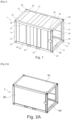
- FIG. 1 And 12 an example of a box 1 according to the invention, of generally parallelepiped shape, comprising a framework 10 carrying side walls 30, an upper wall 40, and a floor 80.
- the latter is for example made of wood 81 and is supported by a trellis formed by metal plates 82 and by two transverse sheaths 83.
- the frame 10 is tubular, comprising uprights 11, longitudinal tubes 12 and crosspieces 13 extending like the edges of a parallelepiped, joined at their ends by pieces of corner 20, represented separately on the figures 3A to 3F .
- the trellis formed by the plates 82 is connected to the longitudinal tubes 12 and to the lower crosspieces 13, as well as to the sleeves 83. The latter are engaged in cutouts of the lower longitudinal tubes 12, and their ends define openings 70 for the insertion forks of a forklift, in order to be able to lift the box 1 if necessary.
- the box 1 has at its ends sectional sliding doors 60, guided by vertical rails 61 parallel to the uprights 11.
- Plates 50 are attached to the beams 12 and crosspieces 13 on the upper and lower faces of the box 1, to stiffen the connections and protect the box against a risk of perforation in the event of mishandling.
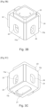
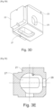
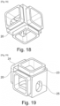
- the corner pieces 20 behave as shown in the figures 3A to 3F a body 21, for example made of aluminum or aluminum alloy, of generally cubic shape, provided on three of its faces with end pieces (or male parts) 22, 23 and 24 intended to fit into the tubes of the frame 10 and to be welded thereto.
- This interlocking increases the extent of the zone of welding of the tubes to the corner pieces, and consequently reinforces the rigidity and solidity of the assembly.
- the weld zones are exposed to a vibratory system which causes a relaxation of the mechanical stresses in the welds in order to improve their elastic deformation capacity and reduce the risks of rupture or deformation.
- the ends 22 of the corner fittings 20 may still be hollow, as illustrated in the figures 18 and 19 .
- Each corner piece 20 has two openings 25 and 26 on its faces 11a and 11b, and an opening 27 on a face 11c, in order to serve as attachments for twist locks called “twist locks” according to the ISO 1161:1984 standard.
- corner pieces 20 have been shown intended to be arranged in one of the right or left corners of the body, the corner pieces 20 intended for the various corners being made in a similar manner, except for symmetry according to their position on the body, so that the openings 25, 26 and 27 have the desired layout and orientation.
- the openings 27 are oriented upwards and downwards, with their long axis in the direction of the length of the body, as visible on the figure 1 , while the openings 25 and 26 are oriented with their major vertical axis on the sides and in the direction of the height.
- the side walls 30 are in this example made with a folded sheet, so as to benefit from an increased mechanical resistance while using a thin sheet, for example 3mm in aluminum or aluminum alloy, which makes it possible to gain in lightness. .
- the side walls 30 may also not include any bent sheet metal, and for example not be structural, being formed for example simply by an anti-burglary tarpaulin or a cladding, optionally lined with reinforcing elements, as will be detailed below.
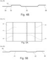
- FIG. 4A And 4B an example of folding the side wall 30; the latter comprises for example a first double fold 33 at 45° ending in a first plate 31, a second double fold 34, then a third double fold 35 at 45° ending in a second plate 38 coplanar with the first.
- the roof may have less deep folds than on the side walls because the roof is less mechanically stressed than the side walls. In addition, the lesser depth of the folds of the roof leaves more room for the passage of the door, and gives more height to enter the body without having to lower the head.
- the plies of the bottom roof are 30mm thick and those of the side walls 57mm, for a wall thickness of 3mm.
- the side and roof walls may have at least one common pattern formed by the folding, for example 700mm wide.
- the roof may still not comprise a folded sheet, but simply a flat sheet, which may be in one piece over the entire length of the body, or formed of several juxtaposed plates, as will be described later.
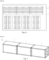
- three boxes 1 can be assembled end to end by twist locks inserted in the adjacent corner fittings 20, as illustrated in figure 7 , to form a one-piece assembly 100 in the format of a shipping container. They can also be positioned one after the other on a container trailer and fixed individually to the trailer using twist locks.
- FIG. 13 An example of a device 400 with twistlocks has been shown on the figure 13 , of the "Twist-lock" type.
- This device comprises in this example two latches 401 and 402 intended to engage in the openings of the corners 20 of two adjacent boxes and to lock there automatically by a quarter turn when bringing the boxes together.
- the locks 401 and 402 can be rotatable relative to a body 404 which retains them axially.
- Springs 405 and 406 can maintain the locks in the locked position in the absence of intervention on an unlocking mechanism (not shown), for example a lever.
- the resistance of the crates 1 allows them to be stacked as illustrated in figure 9 ; it is possible to stack two loaded boxes 1 or three empty boxes 1.
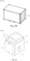
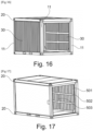
- FIG. 14 to 17 and 20 there is shown a box 1 according to a variant of the invention, without side walls or roofs formed of bent sheets.
- the side walls 30 are formed for example by a siding 501, visible on the figure 17 in particular, lined with horizontal 502 and vertical 503 interior reinforcement elements, which make it possible to secure the loads inside the box, in addition to a securing to the floor.
- These reinforcing elements 502 and 503 can be formed from metal plates joined at their intersections and fixed at their ends to the beams 12 and uprights 11. These plates are for example 100 mm wide.
- the reinforcing elements 502 and 503 can be positioned along the walls transversely and longitudinally as shown, the height of the horizontal reinforcements can be modified to provide a different interior layout of the body.
- the 501 cladding can be replaced by wood or a burglar-proof tarpaulin.
- the roof can be composed as shown in the figure 15 three aluminum sheets 40a, 40b and 40c, arranged next to each other in the direction of the width to correspond to the standard dimensions of the aluminum sheets found on the market. This reduces cutting operations and scrap material during manufacturing.
- the roof can also be formed from a one-piece sheet extending over the entire length of the body between the upper crosspieces 13.
- the body 1 may have longitudinal 510 and transverse 511 reinforcement elements, under the roof plate, as illustrated in the figure 20 .
- These reinforcing elements are for example made up of metal plates oriented perpendicular to the sheet metal of the roof, joined at their intersections and fixed at their ends to the beams 12 and the crosspieces 13.
- the body 1 may include bracing brackets 520 in each angle formed between an upright 11 and a beam 12, as illustrated in the figure 20 .
- This coupling 200 comprises a frame 214 (also called subframe) provided with an axle 210; the frame 214 comprises longitudinal members on which crosspieces 211 and 212 are fixed, provided at their ends with fasteners 213 of the twist-lock type which can be engaged in the corner fittings 20 of the body 1.
- the hitch 200 can be coupled to a light vehicle 300, as illustrated in figure 11 , for example according to the binding systems marketed by the company MAXICARGO.
- the boxes 1 according to the invention can be used in the following way.
- the boxes 1 are assembled when empty to form a one-piece assembly 100; the doors 60 can be raised to facilitate movement inside the assembly and the placement of the load.
- the set 100 can be transported by river like other shipping containers to an urban or peri-urban area; the goods may be present on pallets; then, the boxes 1 are separated from each other without being emptied of their goods; each crate 1 can be placed on a hitch 200 as described above, then carried by a utility vehicle 300 or a carrier vehicle with a GVW of less than or equal to 7.5t to its destination, to deliver the goods contained inside .
- the unloading of goods on pallets can be done with a tailgate of the vehicle.
- This subframe 400 is for example mainly made of steel, and comprises at least two parallel longitudinal members 401 connected in the example illustrated by two short crosspieces 402 and three long crosspieces 403.
- the long crosspieces 403 are located for example at the two ends of the longitudinal members 401 at the front and at the rear of the subframe, as well as substantially in the middle thereof.
- the long front crosspiece and the middle one are connected by bars forming cyclist guards 405, intended to extend along part of the vehicle frame.
- the front and rear long crosspieces 403 carry at their ends locks 213 for fixing the container, for example of the twist lock type, intended to engage in corresponding openings of the lower corner pieces 20 of the container resting on the subframe. .
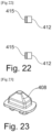
- the subframe 400 also comprises, at the front, a vertical frame 410 serving as a protective stop for the cabin of the vehicle.
- This frame 410 comprises for example, as shown, two uprights 411 connected at their lower end to the long front crosspiece 403, and connected to each other by two horizontal bars 412.
- the frame 410 can be lined on the container side with a synthetic lining 415, for example made of rubber, as illustrated in the figure 22 in order to protect the aluminum of the body from rubbing against the steel of the frame.
- a synthetic lining 415 for example made of rubber
- the frame of the boxes can be made differently, with tubes having a different section profile, for example circular or rectangular.
Landscapes
- Engineering & Computer Science (AREA)
- Mechanical Engineering (AREA)
- Transportation (AREA)
- Management, Administration, Business Operations System, And Electronic Commerce (AREA)
- Pallets (AREA)
Applications Claiming Priority (2)
| Application Number | Priority Date | Filing Date | Title |
|---|---|---|---|
| FR2110639A FR3127937A1 (fr) | 2021-10-07 | 2021-10-07 | Caisse pour le transport de marchandises |
| FR2203825A FR3127936A1 (fr) | 2021-10-07 | 2022-04-25 | Caisse pour le transport de marchandises |
Publications (2)
| Publication Number | Publication Date |
|---|---|
| EP4163224A2 true EP4163224A2 (de) | 2023-04-12 |
| EP4163224A3 EP4163224A3 (de) | 2023-08-02 |
Family
ID=83508598
Family Applications (1)
| Application Number | Title | Priority Date | Filing Date |
|---|---|---|---|
| EP22199846.1A Pending EP4163224A3 (de) | 2021-10-07 | 2022-10-05 | Kasten zum transport von gütern, satz aus drei kasten, anhänger, transportsystem und transportverfahren |
Country Status (1)
| Country | Link |
|---|---|
| EP (1) | EP4163224A3 (de) |
Citations (8)
| Publication number | Priority date | Publication date | Assignee | Title |
|---|---|---|---|---|
| US3317219A (en) | 1965-06-04 | 1967-05-02 | Hindin Eugene | Vehicle formed by coupleable containers with demountable adapter frames |
| US3480174A (en) | 1967-08-02 | 1969-11-25 | James B Sherwood | Assembly of freight containers and foundation frame for use therewith |
| WO1987004994A1 (en) | 1986-02-21 | 1987-08-27 | Tcs Containers Pty Ltd. | Cargo containers |
| WO2001062631A2 (en) | 2000-02-23 | 2001-08-30 | Federal Express Corporation | Freight container, system, and method for shipping freight |
| US6474927B1 (en) | 1996-10-11 | 2002-11-05 | Federal Express Corporation | Freight container, system, and method for shipping freight |
| US20060113302A1 (en) | 2004-09-09 | 2006-06-01 | Inteligistics, Inc. | Modular shipping unit and system |
| US20060118504A1 (en) | 2004-12-06 | 2006-06-08 | Willemsen Robert P | Modular intermodal container |
| DE102009051795B3 (de) | 2009-11-03 | 2011-04-07 | Deutsches Zentrum für Luft- und Raumfahrt e.V. | Container, daraus gebildete Transporteinheit und Containersystem |
Family Cites Families (4)
| Publication number | Priority date | Publication date | Assignee | Title |
|---|---|---|---|---|
| FR2649430B1 (fr) * | 1989-07-07 | 1995-09-08 | Bardou Christian | Construction modulaire transportable |
| US10479257B1 (en) * | 2017-05-25 | 2019-11-19 | King Kutter Ii, Inc. | Road trailer with lift frame for transporting and deploying legged containers |
| CN108638939B (zh) * | 2018-05-14 | 2021-05-14 | 中国重汽集团成都王牌商用车有限公司 | 一种具有可拆卸式货箱的车辆及其操作方法 |
| CN112918580B (zh) * | 2021-03-31 | 2024-07-09 | 太原理工大学 | 一种副车架内嵌的运输与自卸两用式骨架集装箱半挂车 |
-
2022
- 2022-10-05 EP EP22199846.1A patent/EP4163224A3/de active Pending
Patent Citations (8)
| Publication number | Priority date | Publication date | Assignee | Title |
|---|---|---|---|---|
| US3317219A (en) | 1965-06-04 | 1967-05-02 | Hindin Eugene | Vehicle formed by coupleable containers with demountable adapter frames |
| US3480174A (en) | 1967-08-02 | 1969-11-25 | James B Sherwood | Assembly of freight containers and foundation frame for use therewith |
| WO1987004994A1 (en) | 1986-02-21 | 1987-08-27 | Tcs Containers Pty Ltd. | Cargo containers |
| US6474927B1 (en) | 1996-10-11 | 2002-11-05 | Federal Express Corporation | Freight container, system, and method for shipping freight |
| WO2001062631A2 (en) | 2000-02-23 | 2001-08-30 | Federal Express Corporation | Freight container, system, and method for shipping freight |
| US20060113302A1 (en) | 2004-09-09 | 2006-06-01 | Inteligistics, Inc. | Modular shipping unit and system |
| US20060118504A1 (en) | 2004-12-06 | 2006-06-08 | Willemsen Robert P | Modular intermodal container |
| DE102009051795B3 (de) | 2009-11-03 | 2011-04-07 | Deutsches Zentrum für Luft- und Raumfahrt e.V. | Container, daraus gebildete Transporteinheit und Containersystem |
Also Published As
| Publication number | Publication date |
|---|---|
| EP4163224A3 (de) | 2023-08-02 |
Similar Documents
| Publication | Publication Date | Title |
|---|---|---|
| US10518690B2 (en) | Intermodal tank transport system, components, and methods | |
| CA2296616C (en) | Transport cart system and method of its manufacture and operation | |
| EP2847112B1 (de) | Gestell zum lagern und/oder transportieren von grossen glasscheiben | |
| EP2969850B1 (de) | Intermodale miniversandbehälter und verfahren zur verwendung davon | |
| WO2009080970A2 (fr) | Vehicule porte-conteneurs | |
| US20170021999A1 (en) | Inter-modal shipping mini-containers and method of using same | |
| FR2919542A1 (fr) | Vehicule porte-conteneurs | |
| EP4163224A2 (de) | Kasten zum transport von gütern, satz aus drei kasten, anhänger, transportsystem und transportverfahren | |
| FR3127936A1 (fr) | Caisse pour le transport de marchandises | |
| US20080179321A1 (en) | Vehicle storage and shipping container | |
| EP1434708B1 (de) | Schienenfahrzeug für gemischte verwendung für kombinierten schienen/strassentransport von strassenfahrzeugen | |
| WO2008140416A1 (en) | A transport and/or storage container | |
| NZ243917A (en) | Cargo loading lightweight platform for placement within shipping | |
| EP3556676A1 (de) | Einheit für den transport von stahldrahtrollen | |
| EP3494071B1 (de) | Zusammenklappbarer behälter, verfahren zum zusammenfalten eines containers, verfahren zum auseinanderfalten eines containers | |
| EP2341007B1 (de) | Transportsystem und Behälter dafür | |
| US20190389651A1 (en) | Transport platform | |
| EP1541521A1 (de) | Plattform für einen Gabelstapler | |
| FR3165834A1 (fr) | Agencement pour véhicule utilitaire comprenant un hayon élévateur muni d’un moyen d’accrochage pour soulever un conteneur. | |
| FR2919546A1 (fr) | Vehicule porte-conteneurs. | |
| EP4180350A1 (de) | Faltbares verpackungsmodul für eine palette zur bildung eines lager- und transportbehälters | |
| FR3082800A1 (fr) | Benne de transport mixte | |
| FR3119164A1 (fr) | Caisson C pour le transport Fluvial/Route de marchandises | |
| FR3161621A1 (fr) | Structure de transport de vehicule | |
| FR3149599A1 (fr) | Benne amovible pour conteneurs amovibles |
Legal Events
| Date | Code | Title | Description |
|---|---|---|---|
| PUAI | Public reference made under article 153(3) epc to a published international application that has entered the european phase |
Free format text: ORIGINAL CODE: 0009012 |
|
| STAA | Information on the status of an ep patent application or granted ep patent |
Free format text: STATUS: THE APPLICATION HAS BEEN PUBLISHED |
|
| AK | Designated contracting states |
Kind code of ref document: A2 Designated state(s): AL AT BE BG CH CY CZ DE DK EE ES FI FR GB GR HR HU IE IS IT LI LT LU LV MC ME MK MT NL NO PL PT RO RS SE SI SK SM TR |
|
| PUAL | Search report despatched |
Free format text: ORIGINAL CODE: 0009013 |
|
| AK | Designated contracting states |
Kind code of ref document: A3 Designated state(s): AL AT BE BG CH CY CZ DE DK EE ES FI FR GB GR HR HU IE IS IT LI LT LU LV MC ME MK MT NL NO PL PT RO RS SE SI SK SM TR |
|
| RIC1 | Information provided on ipc code assigned before grant |
Ipc: B60P 7/13 20060101ALI20230623BHEP Ipc: B65D 90/00 20060101ALI20230623BHEP Ipc: B65D 88/02 20060101AFI20230623BHEP |
|
| STAA | Information on the status of an ep patent application or granted ep patent |
Free format text: STATUS: REQUEST FOR EXAMINATION WAS MADE |
|
| 17P | Request for examination filed |
Effective date: 20240129 |
|
| RBV | Designated contracting states (corrected) |
Designated state(s): AL AT BE BG CH CY CZ DE DK EE ES FI FR GB GR HR HU IE IS IT LI LT LU LV MC ME MK MT NL NO PL PT RO RS SE SI SK SM TR |
|
| STAA | Information on the status of an ep patent application or granted ep patent |
Free format text: STATUS: EXAMINATION IS IN PROGRESS |
|
| 17Q | First examination report despatched |
Effective date: 20250212 |