EP4163731A1 - Récipient de toner et système de formation d'images - Google Patents
Récipient de toner et système de formation d'images Download PDFInfo
- Publication number
- EP4163731A1 EP4163731A1 EP22199746.3A EP22199746A EP4163731A1 EP 4163731 A1 EP4163731 A1 EP 4163731A1 EP 22199746 A EP22199746 A EP 22199746A EP 4163731 A1 EP4163731 A1 EP 4163731A1
- Authority
- EP
- European Patent Office
- Prior art keywords
- toner container
- toner
- projection
- pack
- guide surface
- Prior art date
- Legal status (The legal status is an assumption and is not a legal conclusion. Google has not performed a legal analysis and makes no representation as to the accuracy of the status listed.)
- Granted
Links
Images








































































Classifications
-
- G—PHYSICS
- G03—PHOTOGRAPHY; CINEMATOGRAPHY; ANALOGOUS TECHNIQUES USING WAVES OTHER THAN OPTICAL WAVES; ELECTROGRAPHY; HOLOGRAPHY
- G03G—ELECTROGRAPHY; ELECTROPHOTOGRAPHY; MAGNETOGRAPHY
- G03G21/00—Arrangements not provided for by groups G03G13/00 - G03G19/00, e.g. cleaning, elimination of residual charge
- G03G21/16—Mechanical means for facilitating the maintenance of the apparatus, e.g. modular arrangements
- G03G21/1661—Mechanical means for facilitating the maintenance of the apparatus, e.g. modular arrangements means for handling parts of the apparatus in the apparatus
- G03G21/1676—Mechanical means for facilitating the maintenance of the apparatus, e.g. modular arrangements means for handling parts of the apparatus in the apparatus for the developer unit
-
- G—PHYSICS
- G03—PHOTOGRAPHY; CINEMATOGRAPHY; ANALOGOUS TECHNIQUES USING WAVES OTHER THAN OPTICAL WAVES; ELECTROGRAPHY; HOLOGRAPHY
- G03G—ELECTROGRAPHY; ELECTROPHOTOGRAPHY; MAGNETOGRAPHY
- G03G15/00—Apparatus for electrographic processes using a charge pattern
- G03G15/06—Apparatus for electrographic processes using a charge pattern for developing
- G03G15/08—Apparatus for electrographic processes using a charge pattern for developing using a solid developer, e.g. powder developer
- G03G15/0822—Arrangements for preparing, mixing, supplying or dispensing developer
- G03G15/0865—Arrangements for supplying new developer
-
- G—PHYSICS
- G03—PHOTOGRAPHY; CINEMATOGRAPHY; ANALOGOUS TECHNIQUES USING WAVES OTHER THAN OPTICAL WAVES; ELECTROGRAPHY; HOLOGRAPHY
- G03G—ELECTROGRAPHY; ELECTROPHOTOGRAPHY; MAGNETOGRAPHY
- G03G15/00—Apparatus for electrographic processes using a charge pattern
- G03G15/06—Apparatus for electrographic processes using a charge pattern for developing
- G03G15/08—Apparatus for electrographic processes using a charge pattern for developing using a solid developer, e.g. powder developer
- G03G15/0822—Arrangements for preparing, mixing, supplying or dispensing developer
- G03G15/0865—Arrangements for supplying new developer
- G03G15/0867—Arrangements for supplying new developer cylindrical developer cartridges, e.g. toner bottles for the developer replenishing opening
- G03G15/087—Developer cartridges having a longitudinal rotational axis, around which at least one part is rotated when mounting or using the cartridge
-
- G—PHYSICS
- G03—PHOTOGRAPHY; CINEMATOGRAPHY; ANALOGOUS TECHNIQUES USING WAVES OTHER THAN OPTICAL WAVES; ELECTROGRAPHY; HOLOGRAPHY
- G03G—ELECTROGRAPHY; ELECTROPHOTOGRAPHY; MAGNETOGRAPHY
- G03G15/00—Apparatus for electrographic processes using a charge pattern
- G03G15/06—Apparatus for electrographic processes using a charge pattern for developing
- G03G15/08—Apparatus for electrographic processes using a charge pattern for developing using a solid developer, e.g. powder developer
- G03G15/0822—Arrangements for preparing, mixing, supplying or dispensing developer
- G03G15/0865—Arrangements for supplying new developer
- G03G15/0874—Arrangements for supplying new developer non-rigid containers, e.g. foldable cartridges, bags
-
- G—PHYSICS
- G03—PHOTOGRAPHY; CINEMATOGRAPHY; ANALOGOUS TECHNIQUES USING WAVES OTHER THAN OPTICAL WAVES; ELECTROGRAPHY; HOLOGRAPHY
- G03G—ELECTROGRAPHY; ELECTROPHOTOGRAPHY; MAGNETOGRAPHY
- G03G21/00—Arrangements not provided for by groups G03G13/00 - G03G19/00, e.g. cleaning, elimination of residual charge
- G03G21/16—Mechanical means for facilitating the maintenance of the apparatus, e.g. modular arrangements
- G03G21/1642—Mechanical means for facilitating the maintenance of the apparatus, e.g. modular arrangements for connecting the different parts of the apparatus
- G03G21/1647—Mechanical connection means
-
- G—PHYSICS
- G03—PHOTOGRAPHY; CINEMATOGRAPHY; ANALOGOUS TECHNIQUES USING WAVES OTHER THAN OPTICAL WAVES; ELECTROGRAPHY; HOLOGRAPHY
- G03G—ELECTROGRAPHY; ELECTROPHOTOGRAPHY; MAGNETOGRAPHY
- G03G15/00—Apparatus for electrographic processes using a charge pattern
- G03G15/06—Apparatus for electrographic processes using a charge pattern for developing
- G03G15/08—Apparatus for electrographic processes using a charge pattern for developing using a solid developer, e.g. powder developer
- G03G15/0822—Arrangements for preparing, mixing, supplying or dispensing developer
- G03G15/0877—Arrangements for metering and dispensing developer from a developer cartridge into the development unit
-
- G—PHYSICS
- G03—PHOTOGRAPHY; CINEMATOGRAPHY; ANALOGOUS TECHNIQUES USING WAVES OTHER THAN OPTICAL WAVES; ELECTROGRAPHY; HOLOGRAPHY
- G03G—ELECTROGRAPHY; ELECTROPHOTOGRAPHY; MAGNETOGRAPHY
- G03G15/00—Apparatus for electrographic processes using a charge pattern
- G03G15/06—Apparatus for electrographic processes using a charge pattern for developing
- G03G15/08—Apparatus for electrographic processes using a charge pattern for developing using a solid developer, e.g. powder developer
- G03G15/0822—Arrangements for preparing, mixing, supplying or dispensing developer
- G03G15/0877—Arrangements for metering and dispensing developer from a developer cartridge into the development unit
- G03G15/0881—Sealing of developer cartridges
- G03G15/0886—Sealing of developer cartridges by mechanical means, e.g. shutter, plug
-
- G—PHYSICS
- G03—PHOTOGRAPHY; CINEMATOGRAPHY; ANALOGOUS TECHNIQUES USING WAVES OTHER THAN OPTICAL WAVES; ELECTROGRAPHY; HOLOGRAPHY
- G03G—ELECTROGRAPHY; ELECTROPHOTOGRAPHY; MAGNETOGRAPHY
- G03G2215/00—Apparatus for electrophotographic processes
- G03G2215/06—Developing structures, details
- G03G2215/066—Toner cartridge or other attachable and detachable container for supplying developer material to replace the used material
- G03G2215/0663—Toner cartridge or other attachable and detachable container for supplying developer material to replace the used material having a longitudinal rotational axis, around which at least one part is rotated when mounting or using the cartridge
- G03G2215/0673—Generally vertically mounting of said toner cartridge parallel to its longitudinal rotational axis
-
- G—PHYSICS
- G03—PHOTOGRAPHY; CINEMATOGRAPHY; ANALOGOUS TECHNIQUES USING WAVES OTHER THAN OPTICAL WAVES; ELECTROGRAPHY; HOLOGRAPHY
- G03G—ELECTROGRAPHY; ELECTROPHOTOGRAPHY; MAGNETOGRAPHY
- G03G2215/00—Apparatus for electrophotographic processes
- G03G2215/06—Developing structures, details
- G03G2215/066—Toner cartridge or other attachable and detachable container for supplying developer material to replace the used material
- G03G2215/0682—Bag-type non-rigid container
-
- G—PHYSICS
- G03—PHOTOGRAPHY; CINEMATOGRAPHY; ANALOGOUS TECHNIQUES USING WAVES OTHER THAN OPTICAL WAVES; ELECTROGRAPHY; HOLOGRAPHY
- G03G—ELECTROGRAPHY; ELECTROPHOTOGRAPHY; MAGNETOGRAPHY
- G03G2215/00—Apparatus for electrophotographic processes
- G03G2215/06—Developing structures, details
- G03G2215/066—Toner cartridge or other attachable and detachable container for supplying developer material to replace the used material
- G03G2215/0692—Toner cartridge or other attachable and detachable container for supplying developer material to replace the used material using a slidable sealing member, e.g. shutter
Definitions
- the first aspect of the present invention is a toner container comprising an accommodating portion configured to accommodate toner; a discharge portion configured to be provided with an opening for discharging the toner in the accommodating portion to an outside; a rotatable member rotatable about a central axis as a rotational axis relative to the discharge portion in a first rotational direction and a second rotational direction opposite to the first rotational direction; and a projection provided below the opening of the discharge portion and having an inner peripheral surface facing inward in a radial direction of an imaginary circle centered on the central axis, when the toner container is oriented in a predetermined direction in which the central axis extends in a direction of gravity and at least a part of the discharge portion is below the accommodating portion, wherein the opening of the discharge portion faces in the radial direction, wherein when the toner container is oriented in the predetermined direction, the projection has a first downward surface and a second downward surface which face downward, and an upward surface which faces upward, outside the inner peripheral surface and inside
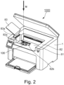
- Part (a) of Figure 1 is a schematic cross-sectional view illustrating a structure of an image forming system 1000 according to Embodiment 1.
- Part (b) of Figure 1 is a perspective view of the image forming system 1000.
- the image forming system 1000 includes an image forming apparatus 1 and a toner pack 100 (toner container, toner cartridge) which can be mounted to the image forming apparatus 1.
- Figure 2 is a perspective view of the image forming apparatus 1 to which the toner pack 100 is not mounted.
- the toner pack 100 is mountable to the mounting portion 106 of the image forming apparatus 1 shown in Figure 2 and contains toner to be supplied to the image forming apparatus 1.
- the detailed structure of the toner pack 100 will be described hereinafter.
- the toner pack 100 is mounted by moving it in the mounting direction M shown in Figure 2 .
- the mounting direction M of the toner pack 100 is the direction of gravity, but the direction M may be inclined relative to the direction of gravity.
- the image forming apparatus 1 is a monochromatic printer which forms an image on the recording material P based on the image information inputted from an external device.
- the recording material P may be various sheet materials such as papers such as plain paper and thick paper, plastic films such as sheets for overhead projectors, sheets having a special shape such as envelopes and index papers, or various sheet materials made of different materials such as cloth.
- the image forming apparatus 1 has the following structure. It comprises an image forming portion 10 that forms a toner image on the recording material P, a pickup roller 65 that feeds the recording material P to the image forming portion 10, a fixing portion 70 that fixes the toner image formed by the image forming portion 10, on the recording material P, and the discharging roller pair 80.
- the image forming portion 10 includes a scanner unit 11, an electrophotographic process unit 20a transfer roller 12 that transfers a toner image as a developer image formed on a photosensitive drum 21 of the process unit 20 to the recording material P.
- the process unit 20 includes a photosensitive drum 21, a charging roller 22, a pre-exposure portion 23, and a developing device 30 (developing unit, developing portion) including a developing roller 31.
- the photosensitive drum 21 (image bearing member) is a photosensitive member molded into a cylindrical shape.
- the photosensitive drum 21 of this embodiment has a photosensitive layer formed of a negatively charged organic photosensitive member on a drum-shaped substrate made of aluminum. Further, the photosensitive drum 21 is rotationally driven by a motor in a predetermined rotational direction (clockwise direction in the Figure) at a predetermined process speed.
- the charging roller 22 contacts the photosensitive drum 21 with a predetermined pressure contact force to form a charging portion. Further, by applying a desired charging voltage by a charging high voltage power source, the surface of the photosensitive drum 21 is uniformly charged to a predetermined potential. In this embodiment, the photosensitive drum 21 is charged by the charging roller 22 to the negative polarity.
- the pre-exposure portion 23 removes static electricity from the surface potential of the photosensitive drum 21 before reaching the charging portion in order to generate a stable discharge in the charging portion.
- the scanner unit 11 as an exposure means scans and exposes a surface of the photosensitive drum 21 by irradiating the photosensitive drum 21 with a laser beam corresponding to image information inputted from an external device, using a polygonal mirror. By this exposure, an electrostatic latent image corresponding to the image information is formed on the surface of the photosensitive drum 21.
- the scanner unit 11 is not limited to the laser scanner device, and, for example, an LED exposure device including an LED array in which a plurality of LEDs are arranged along the longitudinal direction of the photosensitive drum 21 may be employed.
- the developing device 30 includes a developing roller 31 for supplying the developer to the developing roller 31 as a developer carrying member for carrying the developer, a developer container 32 (developing frame) which is the frame of the developing device 30, and a supply roller 33 capable of supplying the developer to the developing roller 31.
- the developing roller 31 and the supply roller 33 are rotatably supported by the developer container 32.
- the developing roller 31 is arranged in the opening of the developer container 32 so as to face the photosensitive drum 21.
- the supply roller 33 is rotatably in contact with the developing roller 31, and the toner as a developer contained in the developer container 32 is supplied to the surface of the developing roller 31 by the supply roller 33.
- the supply roller 33 is not always required, if the toner can be sufficiently supplied to the developing roller 31.
- the developing device 30 of this embodiment uses a contact developing method as a developing method. That is, a toner layer carried on the developing roller 31 is in contact with the photosensitive drum 21 in a developing portion (developing region) where the photosensitive drum 21 and the developing roller 31 face each other. A developing voltage is applied to the developing roller 31 by a developing high voltage power source. Under the developing voltage, the toner carried on the developing roller 31 is transferred from the developing roller 31 to the drum surface in accordance with the potential distribution on the surface of the photosensitive drum 21, so that the electrostatic latent image is developed into a toner image. In this embodiment, a reverse development method is employed.
- the surface of the photosensitive drum is charged in the charging step and then a charge amount is attenuated by the exposure in the exposure step, and the toner adheres to the surface region of the photosensitive drum 21 having the attenuated charge amount, so that a toner image is formed.
- a toner having a particle size of 6 ⁇ m and a negative regular charge polarity is used.
- the toner of this embodiment employs a polymerized toner produced by a polymerization method.
- the toner of this embodiment does not contain a magnetic component, and is a so-called non-magnetic one-component developer in which the toner is supported on the developing roller 31 mainly by an intermolecular force or an electrostatic force (mirror image force).
- a one-component developer containing a magnetic component may be used.
- the one-component developer may contain additives (for example, wax or silica fine particles) for adjusting the fluidity and charging performance of the toner.
- a two-component developer comprising a non-magnetic toner and a magnetic carrier may be used.
- a magnetic developer for example, a cylindrical developing sleeve in which a magnet is arranged inside is used as the developer carrier.
- the contact surface 114b is an end surface (upper surface) on the upstream side in the mounting direction M.
- the contact surface 114f is an end surface on the downstream side in the rotational direction E with respect to the contact surface 114a.
- the rise restricted surface 114c is a surface connecting the contact surface 114a and the contact surface 114f, and is an end (end surface facing upward) surface on the upstream side in the mounting direction M.
- the locking surface 114d is a surface (a surface facing downward) which projects from the outer peripheral surface of the releasing member 114 and faces in the mounting direction M.
- the locked surface 113f of the restricting member 113 is directly below the locking surface 114d of the releasing member 114, and faces the locking surface 114d.
- the releasing claw 114e projects upward from the central hole centered on the rotational axis B of the restricting member 113 beyond the upper surface of the restricting member 113.
- the restricting member 113 and the releasing member 114 are rotatably supported by the large diameter portion 109d1 of the center boss 109d of the apparatus-side shutter 109. Further, the rotation restricting mechanism 112 is covered by the upper surface 110i of the cover 110.
- the center boss 109d is provided coaxially with the rotational axis B of the apparatus-side shutter 109.
- the restricting member 113 is urged in the direction of arrow C of the direction of the rotational axis B by the urging force F1 of the restricting spring 115 (second elastic member, second urging member), and the lower surface 113a thereof contacts the bottom surface 109b of the apparatus-side shutter 109.
- the position of the restriction member at this time is a restriction position.
- the arrow C direction is the mounting direction M of the toner pack 100.
- a release spring 116 (first elastic member, first urging member) is provided between the restricting member 113 and the releasing member 114 in the rotational direction of the apparatus-side shutter 109. One end and the other end of the release spring 116 are engaged with the spring engagement portion 113g of the restricting member 113 and the spring engagement portion 114g of the releasing member 114, respectively.
- the restricting member 113 receives moment M1 in the rotational direction D, So that at least one of the pair of first contact surfaces 113b contacts the corresponding first contact surface 110a of the cover 110.
- the second contact surface 113h of the restricting member 113 contacts the contacted surface 110j (see Figure 8 ) of the cover 110, so that the rotation in the rotational direction D is restricted.
- the releasing member 114 receives moment M2 in the rotational direction E by the urging force F3 of the release spring 116, so that at least one of the pair of contact surfaces 114a contacts the corresponding second contacted surface 110b of the cover 110.
- the cover 110 is integrally fixed to the first frame 107. Therefore, as shown in part (b) of Figure 9 , the restricted rib 109c of the apparatus-side shutter 109 is between the first restriction surface 110c of the cover 110 and the second restricting surface 113c of the restricting member 113. Therefore, the rotation of the apparatus-side shutter 109 in the rotational direction D (direction from the closed position to the open position) is restricted by the second restricting surface 113c of the restricting member 113. The rotation of the apparatus-side shutter 109 in the rotational direction E (direction from the open position to the closed position) is restricted by the first restriction surface 110c of the cover 110.
- the releasing member 114 is provided with an rise restricted surface 114c (rising restricted portion).
- the restricting member 113 moves in the direction of arrow G in a state in which the second contact surface 110b and the contact surface 114a are in contact with each other as shown in part (b) of Figure 9 , the locked surface 113f of the restricting member 113 is brought into abutment to the locking surface 114d of the releasing member 114.
- the same structure is provided on the opposite side with respect to the rotational axis B as the center, and therefore, the restricting member 113 and the releasing member 114 are integrally moved in the direction of arrow G (upward).
- the rise restricting position is the position (region) of the releasing member 114 at the time when the rise restricted surface 114c of the releasing member 114 overlaps with the rise restricting surface 110e of the cover 110 as viewed in the direction of the rotational axis B.
- the amount of rotation of the releasing member 114 in the rotational direction D in the first step suffices if the rise restricted surface 114c of the releasing member 114 does not overlap with the rise restricting surface 110e of the cover 110 as viewed in the direction of the rotational axis B.
- the method of releasing the rotation restriction of the shutter 109 on the apparatus-side is a first step and a second step after the first step.
- the first step is a step of rotating the releasing member 114 from the rise restriction position to the rise restriction release position in the rotational direction D.
- the second step is a step of moving the releasing member upward together with the restricting member 113 so that the restricting member 113 moves from the restriction position to the restriction release position while the releasing member 114 is in the rise restriction release position.
- the second step may or may not include an operation of rotating the releasing member 114 in the rotational direction E until the contact surface 114f of the releasing member 114 abuts to the second contacted surface 110b of the cover 110.
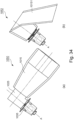
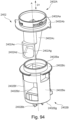
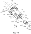
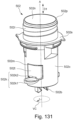
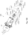
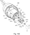
- the toner pack 100 includes an accommodating portion 101 (first accommodating portion) for accommodating toner, a nozzle 102 (nozzle portion, pipe, tube, valve, discharging portion), and a pack-side shutter 103 (container shutter, rotatable member).
- the accommodating portion 101 is provided on the side of the first end portion in the first direction D1
- the nozzle 102 and the pack side shutter 103 are provided on the side of the second end portion opposite from the first end portion in the first direction.
- the accommodating portion 101 is a pouch formed by pouch processing from a flexible polypropylene sheet.
- the accommodating portion 101 is not limited to the pouch, and may be a resin bottle or a container made of paper or vinyl resin material.
- a pack-side shutter 103 (rotatable member) is provided on the outside of the side surface 102c of the nozzle 102.
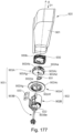
- the pack-side shutter 103 is mounted so as to be rotatable around a rotational axis A (first rotational axis) extending in a direction along the first direction D1, and as shown in Figure 17 , it is provided with an opening 103a (rotatable member opening, first shutter).
- the pack-side shutter 103 is provided outside the side surface 102c in the radial direction r of the imaginary circle VC centered on the rotational axis A.
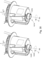
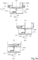
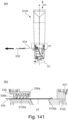
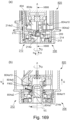
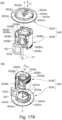
- Part (a) of Figure 18 is an enlarged view of the neighborhood of the nozzle 102 when the pack-side shutter 103 is in the closed position.
- Part (b) of Figure 18 is a view of the toner pack 100 as viewed in the direction of arrow U in part (a) of Figure 18 .
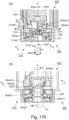
- Part (a) of Figure 19 is an enlarged view of the neighborhood of the nozzle 102 when the pack-side shutter 103 is in the open position.
- Part (b) of Figure 19 is a side view of the toner pack 100 as viewed in the direction of arrow U in part (a) of Figure 19 .
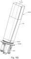
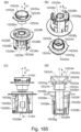
- Figure 20 is a view of the neighborhood of the nozzle 102 as viewed from the side opposite to the side from which Figure 18 views.
- Figure 21 is a view of the neighborhood of the nozzle 102 as viewed in a direction parallel to the surfaces 102d1 and 102d2 of the nozzle 102 (direction perpendicular to the rotational axis A).
- the nozzles 102 is provided with a positioned portion 102d having a surface 102d1 (first nozzle surface, first facing surface) and a surface 102d2 (second nozzle surface, second facing surface) which are arranged in an arrow R direction (second direction D2) so as to face each other with a space therebetween and which extend in a direction perpendicular to the R direction.
- the surfaces 102d1 and 102d2 in this embodiment extend in a direction perpendicular to the arrow R direction and are parallel to each other. That is, the arrow R direction is a normal direction to the surfaces 102d1 and 102d2.
- a straight line CL1 (first imaginary straight line) which passes through the center of the surface 102d1 and the surface 102d2 in the R direction and which extends in the direction perpendicular to the arrow R direction is in a phase rotated by about 90 ° relative to CL2 (second imaginary straight line) which passes through the center of the rotational axis A and the discharge opening 102a. That is, the straight line CL1 and the straight line CL2 are perpendicular to each other.
- the direction of the rotational axis A, the surface 102d1 and the surface 102d2 are provided with surfaces 102e1 and 102e2 on downstream sides in a N direction, respectively.
- the surfaces 102e1 and 102e2 extend in the radial direction r of the imaginary circle VC centered on the rotational axis A.
- a side surface 102e3 (second outer surface) is provided between the surfaces 102d1 and 102d2 and between the surfaces 102e1 and 102e2 in the direction of arrow R.
- the side surface 102e3 is recessed inward in the radial direction r with respect to the side surface 102c.
- the surface 102d1, the surface 102d2, the side surface 102e3, the surface 102e1, the surface 102e2 and the side surface 102e3 form a recess 102e (nozzle recess).
- the surface 102d1 and the surface 102d2 do not necessarily have to be parallel as in this embodiment.
- the surface 102d1 and the surface 102d2 may extend in the radial direction r of the imaginary circle VC centered on the rotational axis A.
- the side surface 103d (the outer surface of the first rotation member) of the pack side shutter 103 is provided with an opening 103a (rotatable member opening).
- the pack-side shutter 103 when the pack-side shutter 103 is in the closed position, at least a part of the recess 102e of the nozzle 102 is exposed through the opening 103a.
- FIG. 20 is an enlarged perspective view of the neighborhood of the pack-side shutter 103 as viewed from the side where the driven transmission portion 103e is provided.
- the driven transmission portion 103e comprises the surface 103b 1, the surface 103b2, and the side surface 103b3.
- the pack-side shutter 103 is provided with a radial positioning portion 103f projecting outward in the radial direction r beyond the side surface 103d.
- the radial positioning portion 103f is provided on the upstream side of the pack side shutter 103 in the N direction of the direction of the rotational axis A.
- the radial positioning portion 103f is provided at each of three locations at intervals in the rotational direction of the pack-side shutter 103 (circumferential direction of the imaginary circle VC).
- the structure is such that when the toner pack 100 is mounted on the mounting portion 106, the radial positioning portion 103f of the pack-side shutter 10 abuts on the inner peripheral surface 109h of the apparatus-side shutter 109 so that the position of the toner pack 100 in the radial direction r is determined.
- the nozzle 102 in this embodiment is a component provided with a passage through which the toner passes and a discharge opening 102a for discharging the toner through the nozzle 102.
- a cross-sectional area of the passage of the nozzle 102 through which the toner passes may be smaller, larger, or even as goes toward the discharge opening 102a.
- the cross-sectional area and length of the passage of the nozzle 102 may be appropriately changed depending on the toner discharging property and the like, and therefore, they are not limited.
- the discharge opening 102a of the nozzle 102 does not have to be the most downstream opening from which the toner is discharged from the toner pack 100.
- the toner discharged from the discharge opening 102a of the nozzle 102 may be discharged to the outside of the toner pack 100 after passing through a passage of a member different from the nozzle 102.
- the pack-side shutter 103 may be a rotatable member including a driven transmission portion 103e and always opening the discharge opening 102a of the nozzle 102 regardless of the rotation position.
- the structure may be such that the discharge opening 102a of the nozzle 102 is closed by a seal when the toner pack 100 is not mounted to the mounting portion 106, and the seal is removed by the mounting operation to the mounting portion 106 or after the mounting of the toner pack 100.
- the toner pack 100 may not be provided with a pack side shutter 103.
- the restriction releasing portion 104 will be described.
- the toner pack 100 is oriented so that the side of the second end portion (the side of the nozzle 102) of the toner pack 100 is below the side of the first end portion (the side of the toner accommodating portion).
- the toner pack 100 is oriented so that at least a part of the nozzle 102 is below the accommodating portion 101 and the rotational axis A is in the vertical direction.
- This attitude is an attitude for mounting on the mounting portion 106 of the image forming apparatus 1.
- the arrow N direction is downward and the arrow U direction is upward.
- the projecting portion 102b projects downward beyond the end surface 103c of the pack-side shutter 103 provided below the discharge opening 102a. Further, as shown in Figure 17 , the projecting portion 102b projects downward beyond a lower end surface 102j of the nozzle 102.
- the end surface 103c of the pack-side shutter 103 and the end surface 102j of the nozzle 102 are end surfaces perpendicular to the rotational axis A, but are not limited to such a structure. These surfaces may be any surface extending in a direction crossing the rotational axis A as viewed in a direction perpendicular to the rotational axis A.
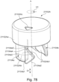
- the outer peripheral surface 102b3 of the projecting portion 102b is provided with a restriction releasing portion 104 including a first restriction releasing portion 104a (first projection) and a second restriction releasing portion 104b (second projection).
- the first restriction releasing portion 104a and the second restriction releasing portion 104b have a symmetric shape with respect to the rotational axis A. That is, as shown in Figure 20 , the second restriction releasing portion 104b is on the opposite side of the first restriction releasing portion 104a with respect to the rotational axis A in the direction perpendicular to the rotational axis A. In other words, the second restriction releasing portion 104b has a shape which is rotationally 180-degree symmetric with respect to the rotational axis A of the first restriction releasing portion 104a.
- the first restriction releasing portion 104a includes a first slope 104a1 (first engaging surface, downward surface, downward guide surface, downward force applying surface, downward push surface) and a second slope 104a2 (second engaging surface upward surface, upward guide surface).
- the first slope 104a1 is below the second slope 104a2 and overlaps with the second slope 104a2 as viewed in the direction of the rotational axis A.
- the first slope 104a1 is a surface which extends so as to go in the arrow U direction (upward) as goes in the rotational direction K (predetermined rotational direction, first rotational direction, first circumferential direction of the imaginary circle VC) about the rotational axis A and which faces in the arrow N direction (downward).
- the second slope 104a2 is a surface extending so as to go in the arrow N direction (downward) as goes in the rotational direction K about the rotational axis A, and is a surface facing the arrow U direction (upward).
- the second slope 104a2 is a surface extending so as to go in the arrow U direction as goes in the rotational direction L (second rotational direction, the second circumferential direction of the imaginary circle VC) about the rotational axis A and facing in the arrow U direction.
- a cavity 104a3 is provided above (directly above) the second slope 104a2.
- the downstream end of the first slope 104a1 and the downstream end of the second slope 104a2 in the rotational direction K are continuous with each other. That is, the downstream end of the first slope 104a1 and the downstream end of the second slope 104a2 in the rotational direction K are at the same position in the rotational direction D. In other words, the downstream end of the first slope 104a1 and the downstream end of the second slope 104a2 are in overlapping positions as viewed in the direction of the rotational axis A.
- the ridge line 104a5 of the first slope 104a1 also extends such that it goes in the direction of the arrow U as goes in the direction of the arrow J perpendicular to the rotational axis A.
- the ridge line 104a4 of the second slope 104a2 also extends such that it goes in the direction of the arrow N as goes in the direction of the arrow J perpendicular to the rotational axis A.
- the ridge line described here is a boundary line between surfaces.
- the ridge line 104a5 is a boundary line between the first slope 104a1 and the outer peripheral surface of the first restriction releasing portion 104a.
- the ridge line 104a4 is a boundary line between the second slope 104a2 and the outer peripheral surface of the first restriction releasing portion 104a.
- the second restriction releasing portion 104b has a first slope 104b1 (downward surface) and a second slope 104b2 (upward surface).
- a cavity 104b3 is provided above the second slope 104b2.
- the first slope 104b1, the second slope 104b2, and the cavity 104b3 have the same structures as the first slope 104a1, the second slope 104a2, and the cavity 104a3 of the first restriction releasing portion 104a, respectively, and therefore, the description thereof will be omitted.
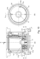
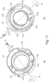
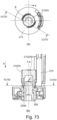
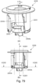
- Figure 22 is a cross-sectional view of the projecting portion 102b taken along a line X33-X33 in Figure 21 .
- Figure 22 shows the second slope 104a2 of the first restriction releasing portion 104a and the second slope 104b2 of the second restriction releasing portion 104b as viewed from above.
- both the second slope 104a2 and the second slope 104b2 extend along the rotational direction of the pack-side shutter 103 (the circumferential direction of the imaginary circle VC centered on the rotational axis A).
- the arrow J direction is parallel to the arrow R direction (second direction) which is the normal direction of the surface 102d1 and the surface 102d2.
- a straight line Q passing through the first restriction releasing portion 104a and the second restriction releasing portion 104b extends in the direction crossing the arrow R direction.
- the positions of the first restriction releasing portion 104a and the second restriction releasing portion 104b are between the position of the surface 102d1 and the position of the surface 102d2 of the positioned portion 102d. That is, as viewed in the direction perpendicular to the rotational axis A (arrow R direction), the positions of the first slope 104a1 and the second slope 104a2 are both between the position of the surface 102d1 and the position of the surface 102d2 in the direction of the arrow R.
- the inclination angles of the first slope 104a1 and the second slope 104a2 with respect to the rotational axis A are in the range of 45 ° ⁇ 15 °.
- a length of the first slope 104a1 in the direction of the rotational axis A is about 2 mm
- a length of the second slope 104a2 is about 3 mm
- a length of the second slope 104a2 is larger than that of the first slope 104a1.
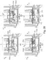
- Part (a) of Figure 23 is a perspective view of the toner pack 100 and the mounting portion 106 while the toner pack 100 is being mounted on the mounting portion 106.
- Part (b) of Figure 23 is a perspective view of the toner pack 100 and the mounting portion 106 as viewed from a point different from that in part (a) of Figure 23 .
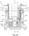
- Figure 24 is a sectional view taken along a line parallel to the rotational axis A (rotational axis B) in a state in which the toner pack 100 is further moved from the state of Figure 23 in the mounting direction.
- Part (a) of Figure 25 is a cross-sectional view taken along a line X4-X4 in Figure 24 .
- Part (b) of Figure 25 is a cross-sectional view taken along a line X5-X5 in Figure 24 .
- Part (a) of Figure 26 is a sectional view taken along a line X6-X6 in Figure 24 .
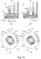
- Part (a) of Figure 26 to 26 (d) are sectional views illustrating a process of mounting the toner pack 100 on the mounting portion 106.
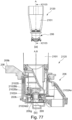
- Part (a) of Figure 27 is a sectional view taken along a line X7-X7 in part (d) of Figure 26 .
- Part (b) of Figure 27 is a cross-sectional view taken along a line X8-X8 in part (a) of Figure 27 .
- the toner pack 100 with the pack-side shutter 103 in the closed position is moved in the mounting direction M relative to the mounting portion 106 with the apparatus-side shutter 109 in the closed position.
- the pack-side shutter 103 is positioned in the rotational direction, to effect alignment between the positions of the recess 102e of the nozzle 102 (opening 103a of the pack-side shutter 103) and the positioning portion 107a of the first frame 107.
- the drive transmission portion 108a (lever projection) of the operating lever 108 and the driven transmission portion 103e (rotatable member recess portion) of the pack side shutter 103 engage with each other.
- the side surface 110f and the side surface 110g of the cover 110 become close to the surfaces 102e1 and 102e2 forming the recess 102e (nozzle recess) of the nozzle 102, respectively.
- the driven transmission portion 103e (rotatable member recess portion) of the pack-side shutter 103 engages with the driven transmission portion 109e (shutter projection) of the apparatus-side shutter 109.
- the rotation restricting mechanism 112 of the mounting portion 106 is released by mounting the toner pack 100 to the mounting portion 106.
- the second restriction releasing portion 104b functions in the same manner as the first restriction releasing portion 104a, and therefore, the description thereof will be omitted.
- this is a step in which the rise restricted surface 114c of the restriction member lifted causes the releasing member 114 to rotate in the rotational direction D against the urging force of the release spring 116 until the it reaches a position where it does not contact the rise restricting surface 110e of the cover 110.
- the movement of the releasing member 114 in the arrow G direction (upward) and the rotation in the rotational direction E are the second steps described in the foregoing.
- the restricting member 113 moves in the arrow G direction together with the releasing member 114.
- at least one of the contact surfaces 114f (pair) of the releasing member 114 is rotationally moved until it comes into contact with one of the second contact surfaces 110b of the corresponding cover 110, thus reaching the mounting completion position shown in part (d) of Figure 26 and Figure 27 .
- the rotation restriction by the rotation restricting mechanism 112 of the apparatus-side shutter 109 is released through the first step and the second step described above.
- FIG. 27 The sectional view of X10-X10 in part (a) of Figure 27 is the same as that in part (a) of Figure 15 , and therefore, the description thereof will be omitted.
- part (b) of Figure 27 which is a cross-section of X8-X8 in part (a) of Figure 27
- the positioning portion 107a of the first frame 107 is engaged with the positioned portion 102d of the nozzle 102 having the surfaces 102d1 and 102d2. Therefore, the nozzle 102 is positioned relative to the first frame 107 (base frame 2) in the arrow R direction of the surfaces 102d1 and 102d2.
- the arrow R direction is substantially parallel to the locus V in which the releasing claw 114e rotates in the rotational direction D when the first restriction releasing portion 104a and the releasing claw 114e come into contact with each other.
- the position of the nozzle 102 is determined relative to the first frame 107 in the direction of the arrow R, And therefore, the operation of releasing the rotation restriction relative to the apparatus-side shutter 109 can be further stabilized.
- the operating lever 108, the pack side shutter 103, and the apparatus-side shutter 109 rotate integrally about the rotational axis A (rotational axis B).
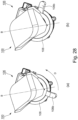
- part (a) of Figure 28 is a perspective view of the toner pack 100 at the time when the operating lever 108 is in the closed position, as viewed from above.
- Part (b) of Figure 28 is a perspective view of the toner pack 100 at the time when the operating lever 108 is in the open position, as viewed from above.
- the restricting member 113 moves upward (in the direction opposite to the mounting direction M) together with the releasing member 114. Then, the second restricted surface 113c of the restricting member 113 is separated upward from the restricted rib 109c of the apparatus-side shutter 109, and the margin for releasing the rotation restriction is increased. Therefore, it is possible to more stably maintain the state in which the rotation restriction for the apparatus-side shutter 109 is released.
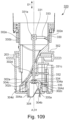
- the toner pack 100 accommodating portion 101 and the toner accommodating chamber 36 are rotated in fluid communication with each other through the discharge opening 102a, the receiving opening 109a, and the apparatus-side opening 117a.
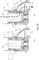
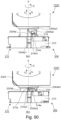
- part (a) of Figure 29 is a sectional view of the toner pack 100 and the mounting portion 106 when both the apparatus-side shutter 109 and the pack-side shutter 103 are in the respective closed positions.
- Part (b) of Figure 29 is a sectional view of the toner pack 100 and the mounting portion 106 when both the apparatus-side shutter 109 and the pack-side shutter 103 are in the respective open positions.
- the discharge opening 102a of the nozzle 102 is closed by the pack side shutter 103, the pack side seal 105, and by the apparatus-side shutter 109, and the toner in the accommodating portion 101 cannot reach the apparatus-side opening 117a of the second frame 117.
- the discharge opening 102a of the nozzle 102 is opened by moving the pack-side shutter 103, the pack-side seal 105, and the apparatus-side shutter 109.
- the toner in the accommodating portion 101 is compressed by the user compressing the accommodating portion 101, the toner in the accommodating portion 101 reaches the apparatus-side opening 117a of the second frame 117 together with the air through the discharge opening 102a, and the toner is supplied into the toner accommodating chamber 36 of the developer container 32 through the side opening 117a.
- first restriction releasing portion 104a and the second restriction releasing portion 104b are provided on the outer peripheral surface 102b3 of the projecting portion 102b of the nozzle 102.
- the following structure may be employed instead.
- a projecting portion 1020b is provided with a restriction releasing portion 1040a corresponding to the first restriction releasing portion 104a of Embodiment 1. However, there is not provided a portion corresponding to the second restriction releasing portion 104b.
- the projecting portion 1021b is provided with a restriction releasing portion 1040b corresponding to the second restriction releasing portion 104b of Embodiment 1. However, there is not provided a portion corresponding to the first restriction releasing portion 104a.
- the first restriction releasing portion 1041a is provided with a second slope 1014a2 corresponding to the second slope 104a2 of Embodiment 1, it does not have a slope corresponding to the first slope 104a1 of Embodiment 1.
- the second restriction releasing portion 1041b has a first slope 1041b1 corresponding to the first slope 104a1 of Embodiment 1, it does not have a slope corresponding to the second slope 104a2 of Embodiment 1.
- the projecting portion 102b is provided with the first restriction releasing portion 104a and the second restriction releasing portion 104b on the outer peripheral surface 102b3 of the cylindrical portion having the hole with the inner peripheral surface 102b1 on the projecting portion end surface 102b2.
- the following structure may be employed instead.
- the first restriction releasing portion 1043a is a first projection including a first slope 1043a1 and a second slope 1043a2 corresponding to the first slope 104a1 and the second slope 104a2 of Embodiment 1, respectively, and is a first projection projecting downward.
- the second restriction releasing portion 1043b has a first slope 1043b 1 and a second slope 1043b2 corresponding to the first slope 104b1 and the second slope 104b2 of Embodiment 1, respectively, and is a second projection projecting downward. There is provided a space between the first restriction releasing portion 1043a and the second restriction releasing portion 1043b.
- two round shaft-shaped bosses may be used as the first restriction releasing portion 1044a and the second restriction releasing portion 1044b, respectively.
- a Y axis extending in the direction of the rotational axis A (arrow U direction) and an X-axis extending in the direction perpendicular to the rotational axis A are defined with the axis of the first restriction releasing portion 1044a as an origin.
- the toner pack 1052 in which the accommodating portion 10151 of the toner pack 1051 hangs down may be used.
- the first restriction releasing portion 104a and the second restriction releasing portion 104b are fixed to the nozzle 102, but they may be movable.
- the structure is such that when the toner pack 1060 is not mounted on the mounting portion 106 of the image forming apparatus 1, the first restriction releasing portion 1046a is accommodated inside (inner peripheral surface 1026b1 side) the outer peripheral surface 1026b3 of the projecting portion 1026b.
- the structure is such that in the process of mounting the toner pack 1060 on the mounting portion 106 of the image forming apparatus 1 or by the user's operation, the first restriction releasing portion 1046a projects to the outside of the imaginary circle VC of the outer peripheral surface 1026b3 of the projecting portion 1026b in the radial direction r.
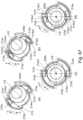
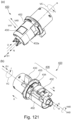
- the structure may be such that when the toner pack 1070 is not mounted to the image forming apparatus 1, the projecting portion 1027b does not project from the end surface 1037c of the pack side shutter 1037, and the projecting portion 1027b project in the direction of the arrow N beyond the end surface 1037c in the process of mounting the toner pack to the image forming apparatus 1. That is, the projecting portion 1027b may be movable so as to take a projected position (projection position) as shown in part (b) of Figure 36 in which it projects (projects) in the arrow N direction beyond the end surface 1037c and the retracted position as shown in part (a) of Figure 36 in which it is retracted in the U direction from the projecting position ( Figure 36 ).
- the projecting portion 1027b may be structured not to project from the end surface 1037c in the retracted position. In such a case, user may manually move the projecting portion 1027b to the projection position and to the retracted position.
- the first restriction releasing portion 1048a is a linear rib extending in the direction of the rotational axis A and has only a surface extending in the direction of the axis A.
- the first restriction releasing portion 1048a has a rotation center 1048a3 at a position between one end and the other end in the direction of the rotational axis A.
- the structure may be such that during or before the process of mounting on the mounting portion 106 of the image forming apparatus 1, the rib is moved (rotated) by the user about the rotation center 1048a3 so as to provide a first slope 1048a1 corresponding to the first slope 104a1 of Embodiment 1 and a second slope 1048a2 corresponding to the second slope 104a2 of Embodiment 1, as shown in part (b) of Figure 37 .
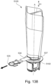
- the nozzle 102 and the projecting portion 102b are integral with each other, but these may be separate members. That is, as shown in Figure 38 , it may be a mounting kit including a toner pack 1090 accommodating the toner and an attachment 1090b, and may be a mounting kit for mounting to image forming mounting.
- the toner pack 1090 has the same structure as that of Embodiment 1 except that the portion corresponding to the projecting portion 102b of Embodiment 1 is not provided, and therefore, the description thereof will be omitted.
- the attachment 1090b has a cylindrical shape having an outer peripheral surface 1029a3 centered on the central axis Z.
- the attachment 1090b is provided with a first restriction releasing portion 1049a and a second restriction releasing portion 1049b on the outer peripheral surface 1029a3 when the central axis Z is oriented in the vertical direction (gravity direction).
- the first restriction releasing portion 1049a has an upward facing surface 1049a2 which faces upward and goes downward as goes in the circumferential direction of the outer peripheral surface 1029a3 (the first circumferential direction KZ of the imaginary circle VCZ centered on the central axis Z).
- the upward surface 1049a2 is configured to extend so as to go up as goes in the second circumferential direction LZ, which is the opposite direction of the first circumferential direction KZ of the imaginary circle VCZ and to face upward 61806180.
- the attachment 1090b also has a downward surface 1049a1 structured to face downward and to extend so as to go up as goes in the circumferential direction (first circumferential direction KZ) of the outer peripheral surface 1029b3. Further, it has a connecting portion 1049a23 which connects the upstream end of the upward surface 1049a2 in the second circumferential direction LZ and the downstream end of the downward surface 1049a1 in the first circumferential direction KZ.
- the attachment 1090b may be structured to be mountable to the bottom surface of the nozzle 1029 of the toner pack 1090 (bottom surface of the toner pack 1090). Further, the attachment 1090b may be structured not to be mounted to the toner pack 1090. That is, the attachment 1090b is first mounted to the mounting portion 106 of the image forming apparatus 1, so that the rotation restriction of the shutter 109 on the apparatus side is released. Then, after mounting the attachment 1090b, the toner pack 1090 is mounted on the mounting portion 106.
- the mechanism by which the rotation restriction of the apparatus-side shutter 109 by the rotation restricting mechanism 112 is released by mounting the attachment 1090b to the mounting portion 106 is the same as the case in which the toner pack 100 is mounted on the mounting portion 106, and therefore, the explanation therefor is omitted.
- Embodiment 2 the structure of Embodiment 2 will be described. The same points as in the above-described embodiment will be omitted. Of the elements disclosed in this embodiment, those corresponding to the members described in Embodiment 1 are assigned the same names as the members of Embodiment 1, and only the points different from those of Embodiment 1 will be described.
- the mounting portion 206 is a unit for mounting the toner pack 220.
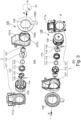
- Part (a) of Figure 40 is an exploded perspective view of a mounting portion 206.
- Part (b) of Figure 40 is an exploded perspective view of the mounting portion 206 as viewed in a direction different from that of part (a) of Figure 40 .
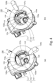
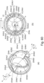
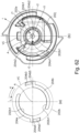
- Part (a) of Figure 41 and part (a) of Figure 42 are a perspective view illustrating the appearance of the mounting portion 206, and a view as seen in the mounting direction M (direction of the rotational axis B), when the operating lever 208 is in the closed position, respectively.
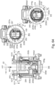
- Part (c) of Figure 44 is a top view of an apparatus-side shutter 209 as viewed in the mounting direction M.
- Part (a) of Figure 45 is a perspective view of a cover 210 as viewed from the upstream side in the mounting direction M.
- Part (b) of Figure 45 is a perspective view of the cover 210 as viewed from the downstream side in the mounting direction M.
- Part (c) of Figure 45 is a top view of the cover 210 as viewed in the mounting direction M.
- Part (d) of Figure 45 is a bottom view of the cover 210 as viewed in the mounting direction M.
- Part (e) of Figure 45 is a side view of the cover 210 as viewed in a direction perpendicular to the mounting direction M.
- the operating lever 208 and the apparatus-side shutter 209 are rotatable about the rotational axis B (central axis) relative to the base frame 221 in the rotational direction D (first rotation) and in the rotational direction E (second rotational direction).
- the rotational direction E is opposite to the direction of the rotational direction D.
- the drive transmission portion 208a of the operating lever 208 is a projection projecting inward from the inner peripheral surface 208d centering on the rotational axis B of the operating lever 208 in the radial direction r of the imaginary circle VC centered on the rotational axis B.
- the apparatus-side shutter 209 is rotated more than a predetermined amount from the closed position to the open position by an impact (vibration) during distribution of the image forming apparatus 1 or by an erroneous operation by the user. If it happened, it might be difficult for the user to mount the toner pack 220 on the mounting portion 206 when using the image forming apparatus 1. Details on this point will be described hereinafter.
- the image forming apparatus 1 of this embodiment is provided with a rotation restricting mechanism 212 in order to restrict the rotation of the shutter 209 on the apparatus side from the closed position to the open position.
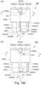
- Part (a) of Figure 46 is a perspective view of a restricting member 213 as viewed from the upstream side in the mounting direction M.
- Part (b) of Figure 46 is a perspective view of the restricting member 213 as viewed from the downstream side in the mounting direction.
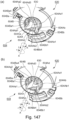
- Part (a) of Figure 47 is a perspective view of a releasing member 214 as viewed from the upstream side in the mounting direction M.
- Part (b) of Figure 47 is a top view of the releasing member 214 as viewed in the mounting direction M.
- Part (c) of Figure 47 is a perspective view of the releasing member 214 as viewed from the downstream side in the mounting direction M.
- Part (d) of Figure 47 is an enlarged view of a releasing claw 214e of the releasing member 214.
- Part (a) of Figure 48 is a perspective view of a unit in which the restricting member 213 and the releasing member 214 are assembled.
- Part (b) of Figure 48 is a top view of the unit in which the restricting member 213 and the releasing member 214 are assembled as viewed in the mounting direction M.
- Part (c) of Figure 48 is a sectional view taken along a line X214-X214 in part (b) of Figure 48 .
- Part (d) of Figure 48 is a bottom view of the unit in which the restricting member 213 and the releasing member 214 are assembled, as viewed in the mounting direction M.
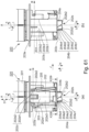
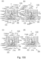
- Figure 49 is a sectional view taken along a X201-X201 in part (a) of Figure 42 , which is a sectional view taken along a line parallel to the rotational axis B in a state in which the rotation of the apparatus-side shutter 209 from the closed position to the open position is restricted by the rotation restricting mechanism 212.
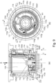
- Part (a) of Figure 50 is a cross-sectional view taken along a line X202-X202 in Figure 49 .
- Part (b) of Figure 50 is a cross-sectional view taken along a line X203-X203 in Figure 49 .
- Part (c) of Figure 50 is a cross-sectional view taken along a line X204-X204 in Figure 49 .
- a restricting member 213, a releasing member 214, a restricting spring 215, and a releasing spring 216 are provided inside the apparatus-side shutter 209.
- the restricting member 213 is an annular member provided with a central hole 213i centered on the rotational axis B.
- the restricting member 213 has a function of restricting the rotation of the apparatus-side shutter 209, which will be described hereinafter.
- the restricting member has a lower surface 213a, a first contact surface 213b, a second contact surface 213h, a second restricting surface 213c (rotation restriction portion), a contacted surface 213e, a pair of locked surfaces 213f, a release spring engaging portion 213g and a restriction spring engaging portion 213k.
- the locked surface 213f is an end surface (upper surface) on the upstream side in the mounting direction M.
- the lower surface 213a is an end surface (bottom surface) on the downstream side in the mounting direction M.
- the release spring engaging portion 213g is a projection projecting in the rotational direction E.
- the restriction spring engaging portion 213k is a recess recessed in the mounting direction M.
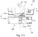
- the releasing member 214 (guided member, engaged member) includes a pair of releasing claws 214e (first engaging claws and second engaging claws, a pair of engaged portions) having shapes of 180-degree rotationally symmetry centered on the rotational axis B.
- the releasing claw 214e extends in the direction opposite to the mounting direction M (upward).
- the releasing claw 214e is provided with a first guided portion 214eA (first contacted portion, first engaged portion) and a second guided portion 214eB (second contacted portion, second engaged portion).
- the second guided portion 214eB is placed at a position which is more remote from the rotational axis B than the first guided portion 214eA in the radial direction r of the imaginary circle VC downwardly in the direction of the axis of rotation B.
- the first guided portion 214eA has a first guided surface 214e1 and a contact surface 214f.
- the second guided portion 214eB has a contact surface 214a, a second guided surface 214e2 (first engaged surface), and a third guided surface 214e3 (second engaged surface).
- the contact surface 214f and the contact surface 214a are end surface s, on the downstream side in the rotational direction E about the rotational axis B, of the releasing claw 214e, and they are at the same positions in the circumferential direction of the imaginary circle VC.
- the contact surface 214a is placed outside the contact surface 214f in the radial direction r of the imaginary circle VC centered on the rotational axis B.
- the first guided surface 214e1 is placed on the upstream side in the mounting direction M with respect to the contact surface 214f. In other words, the first guided surface 214e1 is placed above any of the contact surface 214f, the second guided surface 214e2, and the third guided surface 214e3.
- the second guided surface 214e2 is a surface facing upward.
- the second guided surface 214e2 is placed on the upstream side in the mounting direction M with respect to the contact surface 214a.
- the second guided surface 214e2 is placed above the contact surface 214a.
- the third guided surface 214e3 is a surface facing downward.
- the third guided surface 214e3 is placed on the downstream side in the mounting direction M with respect to the contact surface 214a.
- the third guided surface 214e3 is placed below the contact surface 214a. That is, the second guided surface 214e2 is above the third guided surface 214e3.
- the contact surface 214a is between the second guided surface 214e2 and the third guided surface 214e3 in the mounting direction (direction of rotational axis B, gravity direction).
- the pair of rise restricted surfaces 214c and the pair of locking surfaces 214d are arranged so as to be 180 degrees symmetric with respect to the rotational axis B. As shown in part (a) of Figure 47 to part (c) of Figure 47 , the rise restricted surface 214c projects outward in the radial direction r of the imaginary circle VC beyond the outer peripheral surface centered on the rotational axis B of the releasing member 214.
- the locking surface 214d is a surface (a surface facing downward) which projects from the outer peripheral surface of the releasing member 214 in the direction opposite to the mounting direction M and which faces the mounting direction M.
- the release spring engaging portion 214g is a projection projecting in the rotational direction D.
- the contact surface 214b is a surface facing upward.
- the restricting member 213 and the releasing member 214 are rotatably supported by a large diameter portion 209d1 of the center boss 209d of the apparatus-side shutter 209.
- a part of the rotation restricting mechanism 212 is covered by the upper surface 210i of the cover 210.
- the center boss 209d is provided coaxially with the rotational axis B of the apparatus-side shutter 209.
- a restricting spring 215 (second elastic member, second urging member) is mounted between the cover 210 and the restricting member 213.
- the restricting member 213 is urged in the direction of arrow C in parallel with the rotational axis B by the urging force F201 of the restricting spring 215, and the lower surface 213a (see part (b) of Figure 46 contacts the bottom surface 209b of the apparatus-side shutter 209.
- the arrow C direction is the mounting direction M (gravity direction) of the toner pack 220.
- the releasing spring 216 (first elastic member, first urging member) is mounted between the restricting member 213 and the releasing member 214.
- the restricting member 213 receives a moment M201 in the rotational direction D by the urging force F202 of the releasing spring 216, and the first contact surface 213b of the restricting member 213 is brought into contact with the first contacted surface 210a of the cover 210, or the second contact surface 213h of the restricting member 213 is brought into contact with the second contacted surface 210b of the cover 210.
- the restricting member 213 is restricted from rotating in the rotational direction D.
- the releasing member 114 receives the moment M202 in the rotational direction E by the urging force F203 of the release spring 116, and at least one of the pair of contact surfaces 214a is brought into contact with the corresponding one of the third contacted surfaces 210k of the cover 210.
- the rotation of the releasing member 114 in the rotational direction E is restricted, and the position thereof in the rotational direction E relative to the cover 210 is determined.
- the cover 210 is fixed to the first frame 207. Therefore, as shown in part (a) of Figure 50 , the restricted rib 209c of the apparatus-side shutter 209 is placed between the first restricting surface 210c of the cover 210 and the second restricting surface 213c of the restricting member 213. For this reason, the rotation of the apparatus-side shutter 209 in the rotational direction D (direction from the closed position to the open position) is restricted by the second restricting surface 213c of the restricting member 213. The rotation of the apparatus-side shutter 209 in the rotational direction E (direction from the open position to the closed position) is restricted by the first restricting surface 210c of the cover 210.
- the second step of moving the releasing member 214 in the arrow G direction (upward) shown in Figure 49 is carried out.
- the first step and the second step are executed by the operation of mounting the toner pack 220 on the mounting portion 106. This will be described after explaining the structure of the toner pack 220. Here, only the structure of the mounting portion 206 will be described.
- the contact surface 214b of the releasing member 214 contacts the contacted surface 213e of the restricting member 213, and the releasing member 214 and the restricting member 213 are integrally moved in the direction of arrow G against the urging force F201 of the restricting spring 215.
- the arrow G direction is the direction opposite to the mounting direction M of the toner pack 220.
- the rotation restricting mechanism 212 is structured so that the rotation restriction of the apparatus-side shutter 209 is not released when the rotation restricting mechanism 212 is operated starting at the second step without executing the operation of the first step.
- Part (a) of Figure 52 is a side view of part (a) of Figure 50 as viewed in the direction of arrow G.
- Part (b) of Figure 52 is a sectional view taken along the line X206-X206 of part (a) of Figure 52 .
- Part (c) of Figure 52 shows a state in which the restricting member is moved in the direction of arrow G from the state of part (a) of Figure 52 and part (b) of Figure 52 .
- the cover 210, the restricting member 213, the releasing member 214, the restricting spring 215, and the releasing spring 216 are shown, and the restricting member 213 is not shown in a cross-section.
- the rise restriction release position is the position (region) of the releasing member 214 when the rise restricted surface 214c of the releasing member 214 does not overlap with the rise restricting surface 210e of the cover 210 as viewed in the direction of the rotational axis B.
- the amount of rotation of the releasing member 214 in the rotational direction D in the first step suffices if it is more than an amount by which, as viewed in the direction of the rotational axis B, the rise restricted surface 214c of the releasing member 214 does not overlap with the rise restricting surface 210e of the cover 210.
- the method of releasing the rotation restriction of the apparatus-side shutter 209 includes a first step and a second step after the first step.
- the first step is a step of rotating the releasing member 214 from the rise restriction release position to the rise restriction release position in the rotational direction D.
- the second step is a step of moving the releasing member upward together with the restricting member 213 so that the restricting member 213 moves from the restriction position to the restriction release position while the releasing member 214 is in the rise restriction release position.
- the second step of this embodiment may include an operation of rotating the releasing member 214 in the rotational direction D or the rotational direction E.
- the arrow N direction is the direction from the accommodating portion 201 toward the nozzle 202, and the U direction is the opposite thereto.
- the arrow N direction and the arrow U direction are directions parallel to the rotational axis A.
- the arrow N direction is the vertical downward direction (gravity direction)
- the arrow U direction is the vertical upward direction.
- Part (a) of Figure 59 is a perspective view of the neighborhood of the nozzle 202 as viewed from the side opposite to that in part (a) of Figure 57 .
- Part (b) of Figure 59 is an enlarged perspective view of the projecting portion 202b of part (a) of Figure 59 .
- Part (c) of Figure 59 is an enlarged view of the projecting portion 202b as viewed in a direction perpendicular to the rotational axis A.
- Part (a) of Figure 60 is an enlarged perspective view of the projecting portion 202b.
- Part (b) of Figure 60 is a partial enlarged view of the projecting portion 202b of part (b) of Figure 57 .
- Part (a) of Figure 61 and part (b) of Figure 61 are a front view and a rear view of the nozzle 202, respectively.
- Part (a) of Figure 61 and part (b) of Figure 61 are illustrations of the neighborhood of the nozzle 202 as viewed in a direction parallel to the surface 202d1 and the surface 202d2 of the nozzle 202 (direction perpendicular to the rotational axis A).
- the arrow R direction is the normal direction of the surface 202d1 and the surface 202d2.
- the positioned portion 202d engages with the positioning portion 207a (part (a) of Figure 40 ) of the first frame 207 when the toner pack 220 is mounted on the mounting portion 206.
- the position of the nozzle 202 in the arrow R direction (the position in the rotational direction about the rotational axis A) relative to the first frame 207 (base frame 221) is determined.
- a driven transmission portion 203b (rotatable member recess) is provided on the outer surface of the pack-side shutter 203 on the opposite side of the rotational axis A of the recess 202e (opening 203a of the pack-side shutter 203) of the nozzle 202, as the neighborhood of the nozzle 202 is viewed in the direction of the rotational axis A (first direction D) when the pack side shutter 203 is in the closed position.
- both the surface 203b 1 and the surface 203b2 of the driven transmission portion 203b extend in a direction perpendicular to the arrow R direction (direction of the rotational axis A).
- the nozzle 202 in this embodiment is includes a passage through which the toner passes and the discharge opening 202a for discharging the toner from the nozzle 202.
- the cross-sectional area of the passage through which the toner of the nozzle 202 passes may be made smaller, larger, or even toward the discharge opening 202a.
- the cross-sectional area and length of the passage of the nozzle 202 may be appropriately changed depending on the required toner discharge, and are not restrictive.
- the discharge opening 202a of the nozzle 202 does not have to be the most downstream opening from which the toner is discharged from the toner pack 220.
- the toner discharged from the discharge opening 202a of the nozzle 202 may be discharged to the outside of the toner pack 220 after passing through a passage of a member different from the nozzle 202.
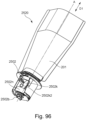
- the nozzle 202 is provided with a projecting portion 202b (projecting portion, engaging portion) which projects (protrudes) in the arrow N direction (downward) beyond the end surface 203c of the pack side shutter 203 in the arrow N direction.
- the projecting portion 202b is a cylindrical portion centered on the rotational axis A.
- the accommodating portion 201, the nozzle 202 (pack side shutter 203), and the projecting portion 202b are arranged in the order named in the N direction, which is the mounting direction of the toner pack 220 to the mounting portion 206.
- the projecting portion 202b projects downward from the end surface 203c of the pack-side shutter 203 beyond the discharge opening 202a.
- the projecting portion 202b is provided on the nozzle 202 so as to project from the end surface 202j (bottom surface) in the direction of the rotational axis A of the nozzle 202 as shown in part (b) of Figure 62 .
- the projecting portion 202b projects downward beyond the lower end surface 202j of the nozzle 202.
- the end surface 203c of the pack-side shutter 203 and the end surface 202j of the nozzle 202 are end surfaces perpendicular to the rotational axis A, but the present invention is not limited thereto. These surfaces may be any surface if it extends in a direction crossing the rotational axis A as viewed in a direction perpendicular to the rotational axis A.
- an opening width L1 of the nozzle 202 in the direction of the rotational axis A of the discharge opening 202a, and a width L2 measured from the lower end of the discharge opening 202a to the end surface 203c of the pack-side shutter 203 preferably satisfy 0.09 ⁇ L2/L1 ⁇ 2.2.
- the projecting portion 202b projects beyond the end surface 202j of the nozzle 202.
- the end surface 203c of the pack-side shutter 203 and the end surface 202j of the nozzle 202 are end surfaces perpendicular to the rotational axis A, but the present invention is not limited to this example. These surfaces may be any surface which extends in a direction crossing the rotational axis A as viewed in a direction perpendicular to the rotational axis A.
- the projecting portion 202b is provided with a restriction releasing portion 204 including a first restriction releasing portion 204a (first projection) and a second restriction releasing portion 204b (second projection).
- a restriction releasing portion 204 including a first restriction releasing portion 204a (first projection) and a second restriction releasing portion 204b (second projection).
- Detailed structures of the restriction releasing portion 204 will be described, referring to part (b) of Figure 59 , part (c) of Figure 59 , part (a) of Figure 60 , part (b) of Figure 60 , part (a) of Figure 62 , and part (b) of Figure 62 .
- the first restriction releasing portion 204a includes a first slope 204a1 (first inner engaging surface, first downward surface, first downward guide surface, first force applying surface, first push surface), a second slope 204a2 (first outer engaging surface, second downward surface, second downward guide surface, second force applying surface, second push surface) and a third slope 204a3 (second engaging surface, first upward surface, upward guide surface)).
- the first slope 204a1 and the second slope 204a2 have surfaces which face in the arrow N direction (downward) and which extend such that they go in the direction of the arrow U (upward) as go in the rotational direction K (first rotational direction) about the rotational axis A.
- the first slope 204a1 and the second slope 204a2 extend such that they go in the U direction (upward) as go in the first horizontal direction hz1 of the horizontal direction.
- the first slope 204a1 and the second slope 204a2 face in the arrow N direction (downward) and extend such that they go in the arrow U direction as go in the first circumferential direction.
- the third slope 204a3 is a surface which faces the arrow U direction (upward) and which extends such that it goes in the arrow U direction (upward) as goes in the rotational direction L (second rotational direction) about the rotational axis A.
- the third slope 204a3 has the surface which extends such that it goes in the arrow U direction (upward) as goes in the second horizontal direction hz2 which is opposite to the first horizontal direction hz1 of the horizontal direction, as viewed in the direction perpendicular to the rotational axis A.
- the third slope 204a3 faces in the arrow U direction (upward direction) and extend such that it goes in the arrow U direction (upward) as goes in the second circumferential direction.
- the downstream end of the second slope 204a2 in the rotational direction K and the downstream end of the third slope 204a3 in the rotational direction L are connected with each other by a connecting portion 204a23. Further, as shown in part (c) of Figure 59 , as viewed in the direction perpendicular to the rotational axis A, the downstream end of the second slope 204a2 in the first horizontal direction hz1 and the downstream end of the third slope 204a3 in the second horizontal direction hz2 are connected with each other by the connecting portion 204a23.
- the third slope 204a3 is above the second slope 204a2. Viewed in the direction of the rotational axis A, the third slope 204a3 overlaps with the second slope 204a2. In this embodiment, although the entire third slope 204a3 is above the second slope 204a2, It will suffice if at least a part of the third slope 204a3 is above the second slope 204a2.
- At least a part of the first slope 204a1 is placed at a position which is closer to the rotational axis A than the second slope 204a2 in the radial direction r in the circumferential direction of the imaginary circle VC and which is different from that of the second slope 204a2.
- a radius R204a1 measured from the rotational axis A to an inner end (edge line) of the first slope 204a1 is shorter than the radius R204a2 measured from the rotational axis A to the inner end (edge line) of the second slope 204a2. That is, at least a part of the first slope 204a1 is placed closer to the rotational axis A than the second slope 204a2 in the radial direction r.
- the upstream region 204a12 of the first slope 204a1 is on the upstream side of the second slope 204a2 in the rotational direction K.
- the upstream side region 204b12 of the first slope 204b1 is on the upstream side of the second slope 204b2 in the rotational direction K.
- first slope 204a1, the second slope 204a2, the third slope 204a3, the cavity 204a4, and the abutment surface 204a5 are rotated 180 degrees around the rotational axis A, they become the first slope 204b1, the second slope 204b2, the third slope 204b3, the cavity 204b4, and the abutment surface 204b5. Therefore, the detailed description of the second restriction releasing portion 204b will be omitted.
- the second slope 204a2 of the first restriction releasing portion 204a is not provided outside, in the radial direction r, of any region of the first slope 204b1 of the second restriction releasing portion 204b. That is, the first slope 204a1 is provided at a position different from that of the second slope 204b2 in the circumferential direction of the imaginary circle VC.
- the projecting portion 202b is provided on the nozzle 202, but it is not necessarily provided on the nozzle 202.
- Part (b) of Figure 68 and part (c) of Figure 68 are a sectional view taken along a line X213-X213 and a sectional view taken along a line X212-X212 in part (a) of Figure 68 , respectively.
- the toner pack 220 in which the pack-side shutter 203 is in the closed position is moved in the mounting direction M to the mounting portion 206 in which the apparatus-side shutter 209 is in the closed position.
- the user mounts the toner pack 220 on the mounting portion 206 by moving the toner pack 220 in the mounting direction M in a state of being oriented in the predetermined direction described above.
- the mounting direction M is the arrow N direction, that is, the vertical downward direction (gravity direction). Further, the mounting direction M is the direction of the rotational axis A (rotational axis B).
- the drive transmission portion 208a (lever projection) of the operating lever 208 and the driven transmission portion 203b (rotary body recess portion) of the pack side shutter 203 are engaged with each other.
- the rib 203e is inserted into the slit 208c provided in the drive transmission portion 208a.
- the side surface 210f and the side surface 210g of the cover 210 guide the surface 202e1 and the surface 202e2 forming the recess 202e (nozzle recess) of the nozzle 202.
- the driven transmission portion 203b (rotatable member recess portion) of the pack-side shutter 203 engages with the driven transmission portion 209e (shutter projection) of the apparatus-side shutter 209.
- the rotational axis A of the pack-side shutter 203 and the rotational axis B of the apparatus-side shutter 209 are made substantially coaxial.
- the drive transmission portion 208a (lever projection) of the operating lever 208 and the driven transmission portion 203b (rotatable member recess) of the pack side shutter 203 are engaged with each other.
- the driven transmission portion 203b (rotatable member recess portion) of the pack-side shutter 203 is engaged with the driven transmission portion 209e (shutter projection) of the apparatus-side shutter 209.
- the attachment 2102A By engaging (fitting) the inner peripheral surface 2102Ab1 of the attachment 2102A with the center boss 209d, the attachment 2102A is positioned in the radial direction about the rotational axis B with respect to the apparatus-side shutter 209, and the central axis A of the attachment 2102A becomes coaxial with the rotational axis B of the mounting portion 206. Further, the user pushes the attachment 2102A in the direction of arrow N while rotating it in the rotational direction E.
- the releasing member 214 is rotated in the rotational direction D while being guided by the first slope 2104a1.
- the toner pack 2120 having no projection as shown in Figure 76 is mounted to the mounting portion 206 of the image forming apparatus 1 as shown in Figure 77 .
- the toner pack 2120 of this modified example has the same shape as that of Embodiment 2 except for the nozzle 202 shown in Embodiment 2, the description other than the nozzle 2102B will be omitted.
- a cylindrical recess portion 2102Ba is provided coaxially with the central axis A on the first end side in the first direction D1.
- a surface 2102Bb perpendicular to the central axis A is provided on the second end side of the recess 2102Ba in the first direction D1.
- the toner pack 2120 is mounted to the mounting portion 206 in the same manner as in Embodiment 2, and the through hole 203h which is on first end side of the pack side shutter 203 in the first direction D1 and which is coaxial with the central axis A the attachment 2102A engages with the cylindrical portion 2102Aa.
- the packaging size of the toner pack 2120 in the central axis A direction can be reduced as compared with the structure of Embodiment 2.
- the rotation restriction by the rotation restricting mechanism 212 of the apparatus-side shutter 209 can be released as in the other embodiments, by the user mounting the attachment 2102A to the image forming apparatus 1 in advance.
- the rotation restriction by the rotation restricting mechanism 212 of the apparatus-side shutter 209 can be released as in the other embodiments, by the use of mounting the attachment 2102A to the toner pack 2120 in advance.
- the attachment 2102A has been described as having the structure with which the rotation restriction by the rotation restricting mechanism 212 can be released regardless of the beginning phase, in the circumferential direction of the imaginary circle VC, of the mounting of the attachment 2102A to the mounting portion 206.
- a simpler structure such as the attachment 21102A, with which the user aligns and mounts the mounting portion 206 so as to match the phase of the mounting portion 206 around the central axis A.
- a triangular marking portion 21102Ac recessed toward the second end side in the first direction D1 is provided at a position away from the central axis A.
- the nozzle 2102B is provided with a cylindrical recess portion 2102Ba in order to avoid interference with the attachment 21102A already mounted on the mounting portion 206, when the toner pack 2120 is mounted on the mounting portion 206.
- Other structures will be described hereinafter.
- the user mounts the toner pack 2120 on the mounting portion 206. Then, as in Embodiment 2, the rotation restriction by the rotation restricting mechanism 212 of the apparatus-side shutter 209 is released, and the toner can be replenished from the toner pack 2120 into the toner accommodating chamber 36 of the developer container 32.
- the structure of the projecting portion 2102Ab in this modified example can be used not only for the projecting portion 202b of embodiment 2 but also for modified examples of Embodiment 2.
- the attachment 2230 of this modified example has a shutter (rotatable member) 2203 and a projecting member 2202 (projecting member).
- the shutter 2203 and the projecting member 2202 are arranged in the first direction D1.
- the shutter 2203 has a substantially cylindrical shape centered on the central axis A, and has a hollow cylindrical portion 2203a substantially coaxial with the central axis A on the second end side in the first direction D1.
- a cylindrical surface 2203b and a through hole 2203c having a diameter smaller than that of the cylindrical surface 2203b, substantially coaxially with the axis A, in this order from the first end side in the first direction D1.
- the hollow cylindrical portion 2203a is provided with two snap-fit portions 2203k at the positions 180-degree rotational symmetry about the central axis A.
- a shutter opening 2203t (rotatable member opening) is provided on the side opposite from the side provided with the driven transmission portion 2203s with respect to the central axis A.
- the driven transmission portion 2203u has the same structure and function as the driven transmission portion 203b shown in part (b) of Figure 57 and part (a) of Figure 59 of Embodiment 2.
- the shutter opening 2203t has the same structure as the opening 203a shown in part (a) of Figure 57 and part (a) of Figure 61 of Embodiment 2.
- the inner peripheral surface 2202b1 of this modified example is a cylindrical surface having the central axis A.
- the inner peripheral surface 2202b1 is preferably a cylindrical surface or a surface for which a central axis A can be defined as shown in Figure 71 of Embodiment 2.
- first slope 2204a1, the second slope 2204a2, the third slope 2204a3, the cavity 2204a4, and the abutment surface 2204a5 of the projecting member 2202Ab have the same structures as the first slope 204a1, the second slope 204a2, the third slope 204a3, the cavity 204a4 and the abutment surface 204a5 of Embodiment 2, respectively, and they are structured with reference to the central axis A of the inner peripheral surface 2102Ab1.
- the second restriction releasing portion 2204b has a shape which is 180 degrees rotationally symmetric with respect to the rotational axis A of the first restriction releasing portion 2204a, and therefore, the description thereof will be omitted.
- Two projections 2202e projecting from the first cylindrical portion 2202a toward the second end portion in the first direction D1 are provided at two positions 180-degree rotational symmetry about the central axis A.
- the projecting member 2202e is provided inside an outer shape of the first cylindrical portion 2202a in the radial direction r of the imaginary circle VC centered on the central axis A, and the central axis A side thereof is connected to the second cylindrical portion 2202c.
- the projections 2202e are each provided with an end surface 2202f which crosses the rotational direction D on the upstream side in the rotational direction D and an end surface 2202g which crosses the rotational direction D on the downstream side in the rotational direction D.
- the projecting member 2202b is inside the width of the shutter opening 2203t in a direction perpendicular to the rotational axis A, as viewed in a direction perpendicular to the rotational axis A so that the shutter opening 2203t of the shutter 2203 faces the front.
- Figure 82 is an exploded perspective view of the attachment 2230 of this modified example.
- Part (a) of Figure 83 and part (b) of Figure 83 are sectional views taken along lines X2201-X2201 and X2202-X2202, respectively in Figure 79 at the time when the projecting member 2202 is placed at the first position relative to the shutter 2203.
- the projecting member 2202 is provided substantially coaxially with the central axis A from the first end side toward the shutter 2203 in the first direction D1.
- the projecting member 2202 is mounted to the shutter 2203 while pushing the two snap-fit portions 2203k of the shutter 2203 in directions away from each other. Thereafter, the projecting member 2202 is supported by the shutter 2203 so that the second cylindrical portion 2202c is fitted in the through hole 2203c of the shutter 2203. Further, the outer circumference of the first cylindrical portion 2202a of the projecting member 2202 is fitted to the cylindrical surface 2203b of the shutter 2203 with slight tightness.
- the first cylindrical portion 2202a of the projecting member 2202 abuts on the surface 2203d of the shutter 2203, and positioning thereof is effected in the first direction D1. Further, the proj ecting member 2202 abuts on the support surface 2203n of the snap-fit portion 2203k of the shutter 2203 on the first end side of the first direction D1, and the hollow cylindrical portion 2203a is sandwiched between the surface 2203d and the support surface 2203n. By this, the projecting member 2202 is restricted so as not to disengage off through the shutter 2203 in the first direction D1.
- the attachment 2230 is moved downward (in the direction of arrow N) toward the mounting portion 206 in a state of being oriented in the predetermined direction described above, and is mounted to the mounting portion 206.
- the driven transmission portion 2203u of the shutter 2203 shown in part (b) of Figure 83 is engaged with the driven transmission portion 209e (shutter projection, see Figure 44 ) of the apparatus-side shutter 209.
- the shutter opening 2203t of the shutter 2203 and the receiving opening 209a of the apparatus-side shutter 209 are brought into fluid communication with each other.
- the inner peripheral surface 2202b 1 of the projecting portion 2202b of the projecting member 2202 is fitted (engaged) with the small diameter portion 209d2 of the center boss 209d of the mounting portion 206.
- FIGS 84 and 85 the operation of the attachment 2230 in association with the rotation of the operating lever 208 from the closed position to the open position will be described in detail.
- Part (a) of Figure 84 , (b) and (c) are enlarged side views of a part of the mounting portion 206 (cover 210, restricting member 213, releasing member 214) and a connecting portion of the attachment 2230, illustrating the operation of the attachment 2230.
- Part (a) of Figure 84 is a side view when the operating lever 208 (not shown) is in the closed position
- part (b) of Figure 84 is a side view of when the operating lever 208 between the closed position and the open position
- part (c) of Figure 84 is a side view when the operating lever 208 is in the open position.
- Part (a) of Figure 85 , Figure (b) and Figure (c) are cross-sectional views taken along a line X2203-X2203 in part (a) of Figure 84 corresponding to part (a) of Figure 84 , part (b) of Figure 84 and part (c) of Figure 84 , respectively.
- Part (a) of Figure 84 and part (a) of Figure 85 show a state in which the attachment 2230 is mounted on the mounting portion 206 and the operating lever 208 is in the closed position.
- the restriction releasing portion of the projecting member 2202b acts on the releasing member 214to release the rotation restriction effected by the rotation restricting mechanism 212 of the apparatus side shutter 209.
- the releasing member 214 since the projecting member 2202b is engaged with the releasing member 214, the releasing member 214 also rotates in the direction of arrow D together with the projecting member 2202.
- the attachment 2230 rotated in the direction of arrow D has stopped moving in the rotational direction by the abutment between the rise restricted surface 214c and the restricting member 213.
- the projecting member 2202 in the rotational direction centered on the central axis A, the projecting member 2202 maintains the first position where the end surface 2202g of the projecting member 2202e abuts against the surface 2203g of the shutter 2203.
- a lid member 2250 may be structured to be mounted to the attachment 2230 while the attachment 2230 is still mounted to the mounting portion 206.
- the operating lever 208 When removing the attachment 2230, the operating lever 208 is rotated from the open position to the closed position in the direction of arrow E. Then, the operating lever 208, the shutter 2203, the projecting member 2202, and the releasing member 214 are interlocked to rotate in an arrow E direction in the reverse order of the operation associated with the rotation from the closed position to the open position described above. At this time, the operating lever moves from the open position to the closed position, and the projecting member 2202 moves from the second position to the first position.
- the mounting kit comprising the attachment 2230 including the projecting member 2202 and the shutter 2203, and the toner pack 2220 including the accommodating portion, it is possible to release the rotation restriction for the shutter 209 by the apparatus-side rotation restricting mechanism 212 and to replenish the toner from the toner pack 2220 to the toner accommodating chamber 36 of the developer container 32, similarly to Embodiment 2.
- the projecting member 2202 is structured to be movable within a predetermined range in the rotational direction about the central axis A relative to the mounting portion 206, but the same effect can be provided even when a positioning portion for positioning in the rotational direction about the central axis A with respect to the cover 210 as in Modified Example 1 without movement.
- the structure of this modified example can be applied to the modified examples of embodiment 2 as well as to the projecting portion 202b of Embodiment 2.
- the first slope 204a1 and the second slope 204a2 of the first restriction releasing portion 204a are different slopes, and the second restriction releasing portion 204b has the same structure.
- the two slopes may have a smoothly continuous surface.
- the structure in this case will be described as an example of this modified example.
- the first slope 204a1 and the second slope 204a2 of the first restriction releasing portion 204a and the first slope 204a1 and the second slope 204a2 of the second restriction releasing portion 204b of this embodiment are changed to have a smoothly continuous surface.
- the structure is the same as that of this embodiment except for this changed portion, and therefore, the description thereof will be omitted.
- Figure 88 is an illustration of detailed shapes of a first restriction releasing portion 2304a (first projection) and a second restriction releasing portion 2304b (second projection) of this modified example.
- Part (a) of Figure 88 is a perspective view of the first restriction releasing portion 2304a and the second restriction releasing portion 2304b as viewed from the side (nozzle side) of the second end portion in the first direction D1.
- Part (b) of Figure 88 is a view of the first restriction releasing portion 2304a as viewed in a direction perpendicular to the rotational axis A.
- Part (c) of Figure 88 is a sectional view taken along a line X2301-X2301 in part (b) of Figure 88 .
- Part (d) of Figure 88 is a view of the first restriction releasing portion 2304a viewed in the direction of arrow U (upward).
- the projecting portion 2302b of the nozzle 2302 is provided with a restriction releasing portion 2304 including the first restriction releasing portion 2304a and the second restriction releasing portion 2304b.
- the first restriction releasing portion 2304a includes a first slope 2304a1 (downward surface, downward guide surface, downward force applying surface, downward push surface), a second slope 2304a2 (upward surface, upward guide surface), abutment surface 2304a3 (downstream side end surface, abutted surface)).
- the first slope 2304a1 faces the arrow N direction (downward), and it goes up in the arrow U direction (upward) as goes in the rotational direction K (first rotational direction) about the rotational axis A.
- an end of the first slope 2304a1 on the side closer to the rotational axis A in the radial direction r of the imaginary circle VC centered on the rotational axis A is referred to as an inner end 2304a4 (inner edge line, inner ridge line).
- the inner end 2304a4 includes an inner upstream end 2304a4U (inner upstream edge line, inner upstream ridge line) on the upstream side in the rotational direction K and, an inner downstream end 2304a4D (inner downstream edge line, inner downstream ridge line) on the downstream side, and an inner intermediate end 2304a4I (inner intermediate edge line, inner intermediate ridge line) connecting them.
- the inner downstream end 2304a4D is more remote from the rotational axis A in the radial direction r of the imaginary circle VC centered on the rotational axis A than the inner upstream end 2304a4U.
- the inner upstream end 2304a4U and the inner downstream end 2304a4D have a first arc and a second arc centered on the rotational axis A, the second arc having a radius larger than that of the first arc as viewed in the direction of the rotational axis A.
- the inner intermediate end 2304a4I extends in the radial direction r so as to connect the first arc and the second arc.
- an end of the first slope 2304a1 on the side remote from the rotational axis A in the radial direction r of the imaginary circle VC centered on the rotational axis A is referred to as an outer end 2304a5 (outer edge line, outer ridge line).
- the outer end 2304a5 includes an outer upstream end 2304a5U (outer upstream edge line, outer upstream ridge line) on the upstream side in the rotational direction K, an outer downstream end 2304a5D (outer downstream edge line, outer downstream ridge line) on the downstream side an outer intermediate end 2304a5I (outer intermediate edge line, outer intermediate ridge line) connecting them.
- the outer downstream end 2304a5D is at a position more remote from the rotational axis A in the radial direction r of the imaginary circle VC centered on the rotational axis A than the outer upstream end 2304a5U.
- the outer upstream end 2304a5U and the outer downstream end 2304a5D have a third arc and a fourth arc centered on the rotational axis A, as viewed in the direction of the rotational axis A, the fourth arc having a radius larger than that of the third arc.
- the outer intermediate end 2304a5I extends in the radial direction r so as to connect the third arc and the fourth arc.
- At least a part of the second slope 2304a2 is provided on the arrow U direction (upward) side of at least a part of the first slope 2304a1.
- the first slope 2304a1 at this time has a first slope inside portion 2304a1I inside the second slope 2304a2 in the radial direction r of the imaginary circle VC centered on the rotational axis A.
- the first slope 2304a1 has a first slope outside portion 2304a1O at substantially the same position, in the radial direction r of the imaginary circle VC centered on the rotational axis A, as the position of the second slope 2304a2.
- at least a part of the inner side 2304a1I of the first slope and at least a part of the outer side 2304a1O of the first slope overlap in the rotational direction K (see also part (d) of Figure 88 ).
- the abutment surface 2304a3 is provided on the arrow U direction side of (above) from the downstream side end, in the rotational direction K, of the first slope inner side 2304a1I. At least a part of the inner side 2304a1I of the first slope and at least a part of the outer side 2304a1O of the first slope overlap with each other in the rotational direction K, and therefore, the abutment surface 2304a3 overlaps with the outer side 2304a1O of the first slope in the rotational direction K.
- the second restriction releasing portion 2304b has a first slope 2304b1 (downward surface, downward guide surface, downward force applying surface) and a second slope 2304b2 (upward surface, upward guide surface, abutment surface 2304b3.
- first restriction releasing portion 2304a and the second restriction releasing portion 2304b have a shape which is 180-degree rotationally symmetric with respect to the rotational axis A. Therefore, the detailed description of the second restriction releasing portion 2304b will be omitted.
- Figure 89 illustrates the operation of rotating the releasing claw 214e by the first slope 2304a1 of the first restriction releasing portion 2304a, and part (a), part (c), and part (e) of Figure 89 show the process.
- part (b) thereof is a sectional view taken along a line X2302-X2302 in the state shown in part (a) of Figure 89
- part (d) thereof is a sectional view taken along a line X2303-X2303 in the state of part (c) of Figure 89
- part (f) thereof is a sectional view taken along a line X2304-X2304-in the state shown in part (e) of Figure 89
- Figure 90 shows an operation in which the releasing claw 214e is moved by the second slope 2304a2 of the first restriction releasing portion 2304a.
- the first slope 2304a1 of the first restriction releasing portion 2304a is brought into contact with the first guided surface 214e1 of the releasing claw 214e.
- the first guided surface 214e1 of the releasing claw 214e contacts the inner side 2304a1I of the first slope of the first restriction releasing portion 2304a.
- the releasing member 214 rotates in the rotational direction D shown in part (a) of Figure 89 by the same operation as in this embodiment. That is, the releasing member 214 is rotated in the rotational direction D by receiving a force while the first guided surface 214e1 is guided by the inner side 2304a1I of the first slope. Then, as shown in part (c) of Figure 89 , the releasing member 214 is in a state of being rotated in the rotational direction D until the first guided surface 214e1 passes the downstream end of the first slope inner side 2304a1I in the rotational direction D.
- the first slope outer side 2304a1O overlaps with the second guided surface 214e2 of the releasing claw 214e in the direction D.
- the first slope 214a1 of the first restriction releasing portion 2304a contacts the second guided surface 214e2 of the releasing claw 214e.
- the second guided surface 214e2 of the releasing claw 214e contacts the outer side 2304a1O of the first slope of the first restriction releasing portion 2304a.
- the releasing member 214 rotates in the rotational direction D shown in part (e) of Figure 89 by the same operation as in this embodiment. That is, the releasing member 214 is rotated in the rotational direction D by receiving a force while the second guided surface 214e2 is guided by the outer side 2304a1O of the first slope.
- the releasing member 214 rotates in the rotational direction D until the second guided surface 214e2 passes the downstream end of the first slope outer side 2304a1O of the first restriction releasing portion 2304a in the rotational direction D.
- the operation up to this point is the first step in this modified example.
- the third guided surface 214e3 of the releasing claw 214e rides on the downstream end of the second slope 2304a2 of the first restriction releasing portion 2304a in the rotational direction D.
- the contact surface 214a and the contact surface 214f of the releasing member 214 abut against the abutment surface 2304a3 of the first restriction releasing portion 2304a. Then, the rotation restriction of the apparatus-side shutter (see Figure 40 ) by the rotation restricting mechanism 212 is released.
- the first slope 204a1 and the second slope 204a2 of the first restriction releasing portion 2304a in the embodiment which this modified example is based on have a smoothly continuous surface, and the first slope 204b1 and the second of the second restriction releasing portion 204b of the base embodiment are made continuous with each other.
- the first slope 2304a1 of the first restriction releasing portion 2304a has an inner intermediate end 2304a4I between the inner upstream end 2304a4U and the inner downstream end 2304a4D of the inner end 2304a4. This is because there is an abutment surface 2304a3. The same applies to the second restriction releasing portion 2304b.
- the projection 23102b of the nozzle 23102 is provided with a restriction releasing portion 23104 including a first restriction releasing portion 23104a (first projection) and a second restriction releasing portion 23104b (second projection).
- the inner end 23104a4 (inner edge line, inner ridge line) of the first slope 23104a1 of the first restriction releasing portion 23104a and the inner end 23104b4 (inner edge line, inner ridge line) of the first slope 23104a1 of the second restriction releasing portion 23104b are smoothly continuous from the upstream side to the downstream side in the rotational direction K.
- Figure 91 shows the shape of the first restriction releasing portion 23104a, and part (a) thereof is a perspective view as seen from the side (nozzle side) of the second end portion in the first direction D1, part (b) is a view as seen from the side (nozzle side) of the second end portion in the first direction D1, and part (c) is a sectional view taken along a line X23104-X23104 in part (a) of Figure 91 .
- the inner end 23104a4 is smoothly continuous toward the outside of the radial direction r of the imaginary circle VC centered on the rotational axis A, as goes toward the downstream side in the rotational direction K.
- the inner end 23104a4 includes an inner upstream end 23104a4U (inner upstream edge line, inner upstream ridge) on the upstream side in the rotational direction K, and an inner downstream end 23104a4D (inner downstream edge line, inner downstream ridge).
- the inner upstream end 23104a4U and the inner downstream end 23104a4D are ends which extend smoothly continuous.
- the inner end 23104b4 includes an inner upstream end 23104b4U (inner upstream edge line, inner upstream ridge) on the upstream side in the rotational direction K and an inner downstream end 23104b4D (inner downstream edge line, inner downstream ridge).
- the inner upstream end 23104b4U and the inner downstream end 23104b4D are ends which extend smoothly continuous.
- the first restriction releasing portion 23104a includes a first abutment surface 23104a5 on the arrow U direction side of (above) the inner end 23104a4 and a second abutment surface 23104a3 on the arrow U direction side of (above) the second slope 23104a2.
- the second restriction releasing portion 23104b includes a first abutment surface 23104b5 on the arrow U direction side of (above) the inner end 23104b4 and a second abutment surface 23104b3 on the arrow U direction side of (above) the second slope 23104b2.
- Figure 92 shows a state in which the releasing claw 214e has released the contact of the first restriction releasing portion 23104a with the inner side 23104a1I of the first slope
- part (a) of Figure 92 is a view as seen in a direction perpendicular to the rotational axis A
- part (b) of Figure 92 is a sectional view taken along a line X2306-X2306 in part (a) of Figure 92
- part (c) of Figure 92 is a cross-sectional view taken along a line X2307-X2307 in part (a) of Figure 92 .
- intersection P230 is set so as to overlap the first slope outer side 2304a1O of the first restriction releasing portion 23104a with respect to the rotational direction K.
- the contact portion between the first abutment surface 23104a5 of the first restriction releasing portion 23104a and the contact surface 214f of the releasing claw 214e is the intersection P230, as shown in part (a) of Figure 92 , the second guided surface 214e2 of the releasing claw 214e overlaps the outer side 23104a1O of the first slope of the first restriction releasing portion 23104a with respect to the rotational direction D.
- the inner upstream end 23104a4U and the inner downstream end 23104a4D of the first restriction releasing portion 2304a in the present modified example constitute the one smoothly continuous inner end.
- the inner upstream end 23104b4U and the inner downstream end 23104b4D of the second restriction releasing portion 23104b constitute one smoothly continuous end (edge line, ridge line).
- the projecting portion 202b (projection) is integrally provided on the nozzle 202, but by providing the projection in another component, it is possible to facilitate reuse the projection having in the complicated shape, thus improving recyclability.
- Figure 93 is an external perspective view of the discharge unit 2402 of this modified example.
- Figure 94 is an exploded perspective view of the discharge unit 2402 of this modified example.
- Figure 95 is a perspective view of the toner pack 2420 to which the discharge unit 2402 of this modified example is mounted.
- the discharge unit 2402 of this modified example has a cylindrical shape, and a nozzle 2402A (discharge portion) and a support member 2402B are arranged substantially coaxially with the rotational axis A.
- a cylindrical portion 2402Aa and a disk portion 2402Ab having a diameter larger than that of the cylindrical portion 2402Aa are arranged substantially coaxially with the rotational axis A, in the order named from the first end side in the first direction D1.
- a toner feed portion 2402Ac projecting toward the second end portion in the first direction D1 is extended.
- the toner feed portion 2402Ac is provided with a discharge surface 2402Ae, which is a surface extending in the rotational axis A direction, on the second end side in the first direction D1.
- a through hole 2402Ad is provided in the nozzle 2402A, penetrates the cylindrical portion 2402Aa, the disk portion 2402Ab, and the toner feed portion 2402Ac from the first end side in the first direction D1, and it is in fluid communication with the discharge surface 2402Ae in a direction substantially perpendicular to the rotational axis A.
- the portion where the through hole 2402Ad penetrates the discharge surface 2402Ae is referred to as a discharge opening 2402Ag (opening).
- the support member 2402B has a genuinely cylindrical shape, and includes a first cylindrical portion 2402Ba, a disk portion 2402Bc having a diameter larger than that of the first cylindrical portion 2402Ba and a second cylindrical portion 2402Be substantially coaxially with the rotational axis A, in this order from the first end portion side in the first direction D1.
- the proj ecting portion 2402Bb projects in the direction of the rotational axis A from an end surface 2402Bg of the second cylindrical portion 2402Be in the direction of the rotational axis A.
- the projecting portion 2402Bb has the same shape as the projecting portion 202b of the nozzle 202 of Embodiment 2, And therefore, the description thereof will be omitted.
- a through hole 2402Bd is provided in the support member 2402B, and penetrates the first cylindrical portion 2402Ba, the disk portion 2402Bc, and the second cylindrical portion 2402Be from the first end side of the first direction D1, and it is extended to the side hole 2402Bf (side opening) of the second cylindrical portion 2402Be.
- an accommodating portion 2401 is mounted to the cylindrical portion 2402Aa without a gap by adhesion or the like (See Figure 95 )
- the nozzle 2402A is provided with a support member 2402B extending from the second end side in the first direction D1 substantially coaxially with the rotational axis A.
- the first cylindrical portion 2402Ba is tightly fitted into a recess (not shown) provided in the disk portion 2402Ab of the nozzle 2402A. In this manner, the support member 2402B is coupled with the nozzle 2402A.
- the discharge opening 2402Ag is disposed at substantially the same position as the position of the discharge opening 202a of the nozzle 202 of Embodiment 2.
- an orientation (direction in the mounting attitude) of the toner pack 2420 in which at least a part of the discharge unit 2402 is below the accommodating portion 201 and the rotational axis A extends in the gravity direction is as a predetermined direction.
- the projecting portion 2402Bb projects downward from the end surface 2402Bg (lower surface) of the support member 2402B. Further, the projecting portion 2402Bb is below the discharge opening 2402Ag.
- the pack side shutter 203 is mounted to the discharge unit 2402 by the same method as in Embodiment 2.
- the method of mounting/dismounting to/from the mounting portion 206 is the same as that of Embodiment 2, and therefore, the description thereof will be omitted.
- the projecting portion 202b can be provided on the support member 2402B, which is a component different from the nozzle 2402A.
- the nozzle 2402A and the support member 2402B are fixed by press-fitting, and can be relatively easily removed from each other. Therefore, only the support member 2402B including the projecting portion 2402Bb having a complicated shape can be easily removed from the toner pack 2420. Therefore, it is possible to facilitate the reuse of the support member 2402B including the projecting portion 2402Bb, thus improving the recyclability.
- Figure 96 is a perspective view of the toner pack 2520 of this modified example.
- Part (a) of Figure 97 is a perspective view of the nozzle 2502 of this modified example.
- Part (b) of Figure 97 is a sectional view of the nozzle 2502 of this modified example.
- the nozzle 202 has a side surface 202c extending in the direction of the rotational axis A (central axis), and the discharge opening 202a is provided on the side surface 202c.
- the discharge opening 2502k2 is provided in an end surface of the cylindrical portion 2502k.
- the nozzle 2502 of this modified example includes a cylindrical portion 2502k (pipe) and a main assembly portion 2502n (pipe support member) which supports the cylindrical portion 2502k.
- the cylindrical portion 2502k has a cylindrical shape, and a substantially circular opening 2502k1 (reception port) is arranged substantially coaxially with the rotational axis A on the first end side in the first direction D1.
- a substantially circular discharge opening 2502k2 (exit) is provided at the end of the cylindrical portion 2502k opposite to the opening 2502k1.
- the discharge opening 2502k2 faces in a direction perpendicular to the rotational axis A.
- the discharge opening 2502k2 faces the outside in the radial direction r of the imaginary circle VC centered on the rotational axis A.
- the opening 2502k1 and the discharge opening 2502k2 are in fluid communication with each other by a communication passage 2502k3.
- the communication passage 2502k3 is a portion having a cylindrical shape bent into a curved shape.
- the opening 2502k1 faces upward and the communication passage 2502k3 faces outward in the radial direction r, as goes downward, when the toner pack 2520 is oriented in the predetermined direction (direction of the mounting attitude) in Embodiment 2.
- the main assembly portion 2502n of the nozzle 2502 is provided with a slope portion 2502m on the first end side in the first direction D1 from the opening 2502k1.
- the slope portion 2502m is in the form of a conical slope substantially coaxial with the rotational axis A, and is a slope which inclines toward the second end side in the first direction D1 as goes to the rotational axis A.
- the toner in the accommodating portion 201 of the toner pack 2520 passes through the cylindrical portion 2502k from the slope portion 2502m, is discharged through the discharge opening 2502k2, and is replenished into the toner accommodating chamber 36 of the developer container 32.
- a projecting portion 2502b projects downward from the lower end surface (bottom surface) of the main assembly portion 2502n when the toner pack 2520 is oriented in a predetermined direction.
- the projecting portion 2502b has exactly the same shape as the projecting portion 202b of Embodiment 2, and therefore, the description thereof will be omitted.
- the nozzle 202 of Embodiment 2 has the same structure as that of Embodiment 2 except that the nozzle 202 is replaced with the nozzle 2502, and therefore, the other description thereof will be omitted.
- the nozzle 2502 is described as a structure in which the main assembly portion 2502n and the cylindrical portion 2502k are combined, but the cylindrical portion and the main assembly portion may be integrally formed. Further, the cylindrical portion 2502k may be a hard member which does not deform, or may be formed of a member which has elasticity and deforms.
- the present invention is not limited to such an example.
- a toner pack 2530 including a nozzle 2503 in which the direction of the discharge opening of the cylindrical portion is variable will be described.
- the projecting portion 2503b and the slope portion 2503m of the nozzle 2503 have the same shape as the above-mentioned projecting portion 2502b and the slope portion 2502m, respectively, and therefore, the description thereof will be omitted.
- Part (a) of Figure 98 and part (b) of Figure 98 are a perspective view and a sectional view of a nozzle 2503 in a state, the discharge opening 2503k2 of the cylindrical portion 2503k faces downward (direction of the rotational axis A), when the toner pack 2530 is oriented in a predetermined direction.
- Part (a) of Figure 99 and part (b) of Figure 99 are a perspective views and a cross-sectional view of the nozzle 2503 in a state in which the discharge opening 2503k2 of the cylindrical portion 2503k faces the outside in the radial direction r.
- the cylindrical portion 2503k is flexible, and the discharge opening 2503k2 faces downward as shown in part (a) of Figure 98 and part (b) of Figure 98 in an unused fresh state.
- the receiving opening 2503k1 for receiving the toner from the accommodating portion 201 faces upward.
- the user can change the direction of the cylindrical portion 2503k so that it faces the outside in the radial direction r.
- the discharge opening 2503k2 of the cylindrical portion 2503k may be structured to face upward or inward in the radial direction r in the unused fresh state. That is, it will suffice if the discharge opening 2503k2 is structured to face the outside in the radial direction r when the toner pack 2530 is mounted on the mounting portion 206.
- the first restriction releasing portion 204a includes the first slope 204a1, the second slope 204a2, the third slope 204a3, and the abutment surface 204a5, and the second restriction releasing portion 204b has the structure of 180-degree rotationally symmetric with respect to the rotational axis A (central axis) of the first restriction releasing portion 204a.
- the present invention is not limited to such a structure. In this modified example, a structure in which the functions of the first restriction releasing portion and the second restriction releasing portion are separated will be described.
- the second restriction releasing portion 2604b (second projection) of this modified example is provided on the opposite side of the rotational axis A from the first restriction releasing portion 2604a (first projection), and is provided at a position different from that of the first restriction releasing portion 2604a in the circumferential direction of the imaginary circle VC (part (c) of Figure 100 ). Further, the first restriction releasing portion 2604a and the second restriction releasing portion 2604b overlap each other when viewed in the radial direction r of the imaginary circle VC (part (b) of Figure 100 ).
- the first restriction releasing portion 2604a includes a second slope 2604a2 (second downward surface, second downward guide surface, second force applying surface) and a third slope 2604a3 (upward surface, an upward guide surface), and an abutment surface 2604a5.
- the second restriction releasing portion 2604b includes a first slope 2604b1 (first downward surface, first downward surface, first force applying surface) and an abutment surface 2604b5.
- the first restriction releasing portion 2604a does not include a slope corresponding to the first slope 2604b1
- the second restriction releasing portion 2604b does not include a slope corresponding to the second slope 2604a2 and the third slope 2604a3.
- the first slope 2604b1 of the second restriction releasing portion 2604b applies the force, while guiding the first guided surface 214e1 of the releasing member 214.
- the releasing member 214 is rotated in the rotational direction D to a position where the second guided surface 214e2 and the third guided surface 214e3 of the releasing member 214 are exposed through the cover 210.
- the second slope 2604a2 of the first restriction releasing portion 2604a rotates the releasing member 214 to the position where, the rise restricted surface 214c does not overlap the rise restricting surface 210e of the cover 210 as viewed in the direction of the rotational axis A.
- the third slope 2604a3 of the first restriction releasing portion 2604 guides the releasing member 214 so that the releasing member 214 moves upward while being rotated in the rotational direction E.
- the toner pack 220 of Embodiment 2 includes the pack side shutter 203, it may have a structure not including the pack side shutter 203.
- a method of supplying toner to the image forming apparatus by using the toner pack 220 not provided with the pack side shutter 203 will be described.
- Part (a) of Figure 101 is a perspective view of a toner pack 2820 not provided with the pack-side shutter.
- Part (b) of Figure 101 , part (c) of Figure 101 and part (d) of Figure 101 are a left side view, a front view, and a right side view of the toner pack 220 without the pack side shutter 203, respectively.
- a nozzle 2802 is provided with a discharge opening 2802a (opening, nozzle opening) and a projecting portion 2802b.
- An accommodating portion 2801 and a nozzle 2802 are shown in a simplified manner in shape for the sake of better illustration, but are exactly the same as those in Embodiment 2.
- a sealing member s1 seals the discharge opening 2802a of the nozzle 2802. One end of the sealing member s1 extends to above the accommodating portion 2801.
- Part (a) of Figure 102 is a perspective view of the toner pack 2820 and the mounting portion 206 in a state in which the toner pack 2820 including no pack-side shutter is mounted on the mounting portion 206.
- Part (d) of Figure 102 shows a rod 2821 to be used to open the apparatus-side shutter 209.
- Part (b) of Figure 102 and 102 (c) are perspective views illustrating the state before and after the user opens the apparatus-side shutter 209 using the rod 2821, respectively.
- Part (d) of Figure 102 is a perspective view of the toner pack 220 and the mounting portion 206 in the state of part (c) of Figure 102 after the sealing member s1 is pulled out.
- the apparatus-side shutter 209 cannot be opened even if the operating lever 208 is operated as described above. Therefore, by mounting the toner pack 2820 on the mounting portion 206, the rotation restriction of the apparatus-side shutter 209 of the rotation restricting mechanism 212 is first released by the projecting portion 2802b (part (a) of Figure 102 ). Thereafter, the rod 2821 is inserted into the gap between the hole portion of the mounting portion 206 and the nozzle 2802, and the free end bending portion 2821a of the rod is engaged with the shutter projection 209i on the apparatus-side (part (b) of Figure 102 ).
- the rod 2821 is moved in the rotational direction D so as to rotate the apparatus-side shutter 209 from the closed position (part (b) of Figure 102 ) to the open position (part (c) of Figure 102 ). Then, the sealing member s1 is pulled out upward to unseal the discharge opening 2802a of the nozzle 2802.
- the accommodating portion 2801 is compressed by the user in this state, the toner is discharged through the discharge opening 2802a of the nozzle 2802 and is supplied into the toner accommodating chamber 36 of the developer container 32 through the apparatus-side opening 217a of the second frame 217.
- the toner pack 220 may not have the shutter 203 on the pack side.
- Figure 103 is an illustration of an appearance of the toner pack 320.
- Figure 104 is an exploded perspective view of the nozzle 302 and the portions assembled to the nozzle 302, and shows the parts assembled from the side of the first end portion (accommodation portion side) in the first direction D1.
- Figure 105 is an exploded perspective view of the nozzle 302 and the portions assembled to the nozzle 302, and shows the parts assembled from the opposite side of the first end portion side (accommodation portion side) of the first direction D1.
- Figure 106 is a perspective view illustrating detailed shape of the restriction releasing member 304.
- the first slope 304a1, the second slope 304a2, and the first abutment surface 304a5 have the same structures as the first slope 204a1, the second slope 204a2, and the abutment surface 204a5 in Embodiment 2, respectively, and therefore, the description thereof is omitted.
- the flat surface 304a3 is perpendicular to the rotational axis A. That is, when the toner pack 320 is oriented in a predetermined direction, the flat surface 304a3 extends in the horizontal direction perpendicular to the direction of gravity.
- the flat surface 304a3 is placed on the arrow U direction side (upward) of least a part of the second slope 304a2.
- Figure 110 is a sectional view illustrating a process in which the restriction releasing member 304 releases the rotation restricting mechanism 212 when the toner pack 320 is mounted to the mounting portion 206.
- the rotation restricting mechanism 212 is shown only by the restricting member 213 and the releasing member 214.
- the states of part (a) of Figure 110 to part (f) of Figure 110 will be described hereinafter.
- Figure 111 is a sectional view illustrating a state when the toner pack 320 is being removed from the mounting portion 206.
- Figure 114 shows the appearance of the toner pack 420, and is a view as seen in a direction perpendicular to the first direction D1.
- part (a) of Figure 114 is a view as seen from the opening 402a side of the nozzle 402
- part (b) of Figure 114 is a view as seen from the side opposite to the opening 402a.
- Figure 115 is an exploded perspective view of the toner pack 420, and is a view as seen from the second end side (nozzle side) of the first direction D1.
- part (a) of Figure 115 is a view as seen from the opening 402a side of the nozzle 402
- part (b) of Figure 115 is a view as seen from the side opposite to the opening 402a.
- the accommodating portion 201 and the pack-side shutter 203 are not shown.
- Figure 116 is an illustration of details of the nozzle 402.
- Figure 117 is an illustration of details of a movable passage 430.
- Part (a) of Figure 118 is a detailed illustration of a cam member 432
- part (b) of Figure 118 is a detailed illustration of an operating member 433
- part (c) of Figure 118 is a details illustration of a shaft member 434.
- the toner pack 420 in this embodiment includes, an accommodating portion 201, a pack side shutter 203, a nozzle 402, a movable passage 430, which have the same shapes of the corresponding elements of embodiment 2, respectively, and as shown in 114 (b), it comprises an operation mechanism 436 including an operating member 433 exposed to the outside.
- the nozzle 402 (accepting member) has a generally cylindrical shape having a cylindrical portion 402c centered on the rotational axis A, and includes an opening 402a (second opening), a sealing member 402a1, a spring hooking portion 402e, a hole portion 402d, and a projecting portion 402b.
- the nozzle 402 has a function of receiving the toner of the accommodating portion 201.
- the opening 402a is provided on the side surface of the opening side cylindrical portion 402c2 extending in the direction of the rotational axis A, and faces the outside in the radial direction r of the imaginary circle VC centered on the rotational axis A.
- the opening 402a is structured to be in fluid communication with the inside of the accommodating portion 201 in a state in which the nozzle 402 is coupled to the accommodating portion 201.
- the opening 402a is provided with seal members 402a1 at opposite ends in a direction perpendicular to the rotational axis A as viewed from the opening 402a.
- the spring hooking portion 402e is on the opposite side of the opening 402a in the radial direction r of the imaginary circle VC centered on the rotational axis A, and is provided in a first space S40 which will be described hereinafter. Further, the spring hooking portion 402e is a projection projecting in the direction of the arrow U (upward).
- first space S40 the space sandwiched between the first hole portion 402d1 and the second hole portion 402d2 is referred to as a first space S40
- second space S41 the space sandwiched between the second hole portion 402d2 and the third hole portion 402d3
- third space S42 the space sandwiched between the third hole portion 402d3 and the fourth hole portion 402d4 is referred to as a third space S42.
- the projecting portion 402b has the same shape as the projecting portion 202b of the nozzle 202 of Embodiment 2, and therefore, detailed description thereof will be omitted.
- the upward opening 430b is an opening provided on the arrow U direction (upward) side and the arrow V41 direction (retracting direction) side, and communicates with the downward opening 430a. Further, an upper seal member 430f is provided on the surface provided with the upward opening 430b so as to surround the upward opening 430b.
- the shaft portion 432c is a substantially cylindrical shaft centered on the rotational axis A41, and projects in the direction of the arrow N (downward).
- Figure 120 is an illustration of the assembly of the operation mechanism 436 (cam member 432, operating member 433, shaft member 434, E-type retaining ring 435) to the nozzle 402.
- the states of part (a) of Figure 120 to part (d) of Figure 120 will be described as appropriate.
- Figure 121 is a perspective view of the toner pack 420, and is a view as seen from the second end side (nozzle side) in the first direction D1. Further, part (a) of Figure 121 is a view as seen from the opening 402a side of the nozzle 402, and part (b) of Figure 121 is a view as seen from the side opposite to the opening 402a.
- the accommodating portion 201 and the pack-side shutter 203 are not shown.
- the tension spring 431 and the movable passage 430 are assembled to the nozzle 402.
- the movable passage 430 is inserted into the opening 402a of the nozzle 402 in the arrow V41 direction (retracting direction) with such an attitude that the downward opening 430a faces in the arrow N direction (downward) and is on the arrow V40 (projecting direction) side.
- the arrow V40 direction and the arrow V41 direction are directions perpendicular to the rotational axis A or the radial directions r.
- the operating member 433 and the shaft member 434 are assembled to the nozzle 402.
- the operating member 433 is inserted into the third space S42 of the nozzle 402 in the direction of an arrow V42 until the rotational axis A41 is aligned with the rotational axis A40.
- the shaft member 434 is inserted into the first hole portion 402d1 relative to the nozzle 402 from the upper end 434f side in the direction of the arrow U.
- the cam member 432 and the shaft member 434 can be integrally rotated around the rotational axis A40. Further, in the direction (downward) of the arrow N, the cam member 432 is constrained from moving relative to the nozzle 402, and the shaft member 434 is constrained from moving relative to the cam member 432. Therefore, the shaft member 434 is in a state where the movement thereof is restricted relative to the nozzle 402 in the direction (downward) of the arrow N.
- part (a) and part (d) are perspective views
- Part (b) and part (e) are sectional views taken along a line X407-X407 of part (b) of Figure 114 in the respective states
- part (c) the cross-section of view taken along a line X401-X401 of b) of part (b) of Figure 122
- part (f) is a cross-sectional view taken along a line X402-X402 of part (e) of this Figure.
- parts (a) and (d) of this Figure are perspective views
- parts (b) and (e) are sectional views taken along a line X407-X407 of part (b) of Figure 114 in the respective states
- part (c) is a cross-sectional view taken along a line X403-X403 of part (b) of this Figure
- part (f) is a cross-section taken along a line X404-X404 of part (e) of this Figure.
- the description will first be made as to a state in which the pack-side shutter 203 shown in part (a) of Figure 122 is in the closed position, and the movable passage 430 is in the second position (retracting position).
- the operating member 433 projects outward from the nozzle 402 in the radial direction r of the imaginary circle VC centered on the rotational axis A. This makes it easier for the user to operate the operating member 433.
- the movable passage 430 receives a force F400 imparted by the tension spring 431 in the direction of arrow V41 (retracting direction) relative to the nozzle.
- the force F400 maintains the movable passage 430 in a second position housed in the nozzle 402.
- the downward opening 430a of the movable passage 430 is closed in the arrow N direction (downward)
- the upward opening 430b is closed in the arrow U direction (upward).
- the upward opening 430b of the movable passage 430 is closed with respect to the accommodating portion 201 (see Figure 114 ) on the arrow U direction (upward) side of the nozzle 402, but it may be open.
- the movable passage 430 overlaps with the pack side shutter 203 in the rotational axis A direction, and also overlaps with the rotational direction K.
- the movable passage 430 overlaps with the pack side shutter 203 as viewed in the radial direction r. That is, the movable passage 430 is hidden by the pack-side shutter 203, thereby preventing the user from touching the movable passage 430.
- the outflow of the toner, to the outside, which has entered the inside of the nozzle 402 from the accommodating portion 201 is prevented by the upper seal member 430f (see part (b) of Figure 122 ) provided in the movable passage 430.
- the cam member 432 is in contact with the first flat pushed surface 430c1a of the movable passage 430.
- the movable passage 430 when the pack side shutter 203 is in the open position, the movable passage 430 is as follows.
- the movable passage 430 projects from the opening 402a of the nozzle 402 in the direction of the arrow V40, and is movable between a first position where the downward opening 430a is exposed to the outside of the toner pack 420 and a second position retracted from the first position in the direction of the arrow V41.
- the push portion 432a of the cam member 432 pushes the first flat pushed surface 430c1a and the first pushed slope 430c1b of the movable passage 430 in this order, and as shown in part (c) of Figure 123 , it comes into contact with the projecting surface 430c3 of the movable passage 430.
- the movable passage 430 is at the position most projecting from the nozzle 402 (most projecting position). Also at this time, the user carries out the operation while feeling the load of the moment M400 in the direction opposite to the rotational direction K40 by the force F403 produced by the tension spring 431.
- the cam member 432 is rotated in the rotational direction K40 by the moment M401.
- the operating member 433 rotated in the rotational direction K40 together with the cam member 432 abuts on the abutment surface 402f of the nozzle 402, and the rotation is stopped (restricted). That is, the rotation, integral with the operating member 433, of the cam member 432 in the rotational direction K40 is also stopped (restricted). Therefore, the movable passage 430 is constrained from moving in the arrow V41 direction (retracting direction) by the cam member 432 which is at rest (restricted) as described above. By this, the operation of the operating member 433 is completed.
- the position of the movable passage 430 at this time is the second position (projecting position).
- the movable passage 430 moves slightly in the V41 direction (evacuation direction), but the amount of movement is so small that the opening 430a of the movable passage 430 remains open in the direction of the arrow N (downward).
- the upward opening 430b of the movable passage 430 remains open to the accommodating portion 201 (see Figure 114 ) placed in the downstream side on the arrow U direction side of (above) the nozzle 402.
- the user when the user operates the operating member 433 in the rotational direction K40 the user carries out the operation while feeling the moment M400 in the direction opposite to the rotational direction K40 (see part (d) of Figure 122 and part (a) of Figure 123 ), during the movable passage 430 being between the second position and the most projecting position. Thereafter, when the movable passage 430 is positioned at the second position, the movement is switched to the moment M401 in the rotational direction K40 opposite to the moment M400 (see part (d) of Figure 123 ), and therefore, the user recognizes the load reduction. Then, the user can recognize the completion of the operation of the operating member 433 by recognizing the load reduction.
- Figure 124 shows a process of inserting the toner pack 420 into the mounting portion 206 and operating the operating lever 208 and the operating member 433.
- part (a) shows a state in which the operating lever 208 is in the closed position
- part (b) shows a state in which the operating lever 208 is in the open position
- part (c) shows a state in which the operating member 433 is further operated to place the movable passage 430 in the second position.
- Figure 125 is a sectional view in a state in which the toner pack 420 is mounted on the mounting portion 206 and the operating lever 208 is in the open position
- part (a) of Figure 125 is a sectional view taken along the rotational axis A and the arrow V40 (projection direction)
- part (b) of Figure 125 is a cross-section taken along a line X405-X405 of part (a) of Figure 125 .
- Figure 126 is a sectional view when the operating member 433 is operated to move the movable passage 430 to the second position
- part (a) of this Figure is a sectional view taken along the rotational axis A and the arrow V40 (projecting direction)
- part (b) is a cross-section taken along a line X406-X406 of part (a).
- the operating lever 208 is first rotated in the rotational direction D as shown in Figure 124 , and then the operating member 433 is rotated in the direction of an arrow K40.
- the apparatus-side seal 211 covers the periphery of the opening 402a of the nozzle 402.
- the downward opening 430a of the movable passage 430 projects from the opening side cylindrical portion 402c2 of the nozzle 402 in the arrow V40 direction (projecting direction) and is opened in the arrow N direction (downward). Then, the movable passage 430 enters the inside of the first frame 207 of the mounting portion 206, and the downward opening 430a of the movable passage 430 is placed inside the first frame 207.
- the toner in the accommodating portion 201 can reach the apparatus-side opening 217a of the second frame 217 by way of the nozzle 402 and the movable passage 430, as indicated by the thick dotted arrow in the Figure.
- the apparatus-side seal 211 covers the periphery of the opening 402a of the nozzle 402 and the periphery of the movable passage 430 to prevent toner scattering.
- the removal of the toner pack 420 from the mounting portion 206 is performed in the reverse process of mounting the toner pack 420 on the mounting portion 206. That is, the operating member 433 is rotated in the rotational direction L40 from the state of part (c) of Figure 124 , and then the operating lever 208 is rotated in the rotational direction E from the state of part (b) of Figure 124 .
- the detailed operation of the movable passage 430 and the like at this time is merely the opposite of the mounting of the toner pack 420 on the mounting portion 206, and the description thereof will be omitted.
- the pack-side shutter 203 not only closes the opening 402a of the nozzle 402, but also closes the downward opening 430a of the movable passage 430. This makes it possible to more reliably prevent the toner from leaking out from the nozzle 402 of the toner pack 420 to the outside.
- the toner when the toner is replenished from the toner pack 420 to the toner accommodating chamber 36 of the developer container 32, the toner can be discharged from a relatively deeper position of the mounting portion 206. This makes it possible to more reliably prevent toner from scattering out during replenishment.
- Figure 127 is a perspective view of the toner pack 520 having the structure of this embodiment.
- Figure 128 is an exploded perspective view of the toner pack 520.
- Figure 129 is a partially exploded perspective view as seen from the opposite direction of the exploded perspective view of Figure 128 .
- Figure 130 is a partially exploded perspective view as seen from the opposite direction of the exploded perspective view of Figure 129 .
- the toner pack 520 includes an accommodating portion 501 (first accommodating portion) for accommodating toner, a seal support member 530, a toner seal 531, a connection ring 532, a nozzle 502, and a pack side shutter 203.
- the accommodating portion 501 in the first direction D1, is provided at the first end portion, and on the second end portion side opposite to the first end portion in the first direction D1, the seal supporting member 530, the toner seal 531, the connection ring 532, the nozzle 502, and the pack-side shutter 203 are provided.
- the accommodating portion 501 includes a pouch formed by pouch processing of a flexible polypropylene sheet.
- the accommodating portion 501 is not limited to the pouch, and may be a resin bottle or a container made of paper or vinyl.
- the seal support member 530 has a generally cylindrical shape centered on the rotational axis A (central axis), and includes an end surface 530aan outer cylindrical portion 530b in this order from the first end side in the first direction D1, and a mounting surface 530c on the side opposite to the end surface 530a.
- the mounting surface 530c is provided on the outside of the outer cylindrical portion 530b and has a flat plate shape perpendicular to the rotational axis A.
- a through hole 530f having an axis parallel to the rotational axis A and an oblong hole 530g are provided at positions substantially symmetric with respect to the rotational axis A.
- the inner cylinder 530d is arranged inside the outer cylindrical portion 530b.
- the end surface 530a and the inner cylinder 530d are connected by a connection surface 530e.
- the connection surface 530e is an inclined surface that is inclined so as to be away from the rotational axis A as goes toward the first end side in the first direction D1 with the rotational axis A as the center.
- an end surface 530h is provided on the second end side (see Figure 128 ).
- the end surface 530h is a flat surface substantially perpendicular to the rotational axis A, and is placed slightly on the first end side in the first direction D1 with respect to the mounting surface 530c.
- connection ring 532 has a substantially cylindrical shape centered on the rotational axis A, and includes an inner peripheral surface 532a, an outer peripheral portion 532b, an end surface 532c placed on the first end side in the first direction D1a second end side end surface 532d placed on the second end side in the first direction D1.
- a thread groove portion 532e is provided at the inner peripheral surface 532a of the connection ring 532.
- bosses 532f and 532g having axes parallel to the rotational axis A are provided at substantially symmetric positions about the rotational axis A so as to project toward the first end side in the first direction D1.
- An opening 532h is provided on the first end side, in the first direction D1, of the inner peripheral surface 532a.
- a toner seal 531 is mounted closely to the end surface 532c so as to seal the opening 532h by adhesion or the like.
- the seal support member 530 is mounted to the connection ring 532 substantially coaxially from the first end side in the first direction D1.
- the through hole 530f and the oblong hole 530g of the seal support member 530 are engaged with the boss 532f and 532g of the connection ring 532, respectively, and the mounting surface 530c of the seal support member 530 is mounted by adhesion or the like on the end surface 532c with the toner seal 531 sandwiched therein.
- the opening 501a (see Figure 128 ) of the accommodating portion 501 is connected to the outer peripheral portion 532b of the connection ring 532 without a gap by adhesion or the like. In this manner, the toner inside the accommodating portion 501 is sealed by the connection ring 532 and the toner seal 531.
- the second end side end surface 532d of the connection ring 532 in the first direction D1 is provided with a recess 532k recessed toward the first end side in the first direction D1.
- the recess portion 532k is recessed in a circumferential shape and is arranged substantially coaxially with the rotational axis A.
- a ring seal 533, of an elastic member having a substantially cylindrical shape, is mounted to the recess 532k so as to be fitted from the second end side in the first direction D1, and is fixed to the connection ring 532 by adhesion or the like.
- the nozzle 502 is connected to the second end side in the first direction D1 of the connection ring 532.
- the thread ridge portion 502r of the nozzle 502 has a shape which is capable of meshing engagement with the thread groove portion 532e provided on the inner peripheral surface 532a of the connection ring 532, and the nozzle 502 and the connection ring 532 are connected by the threading therebetween.
- the disk portion 502s has a disk shape of a generally flat plate substantially coaxial with the rotational axis A, and has an outer diameter larger than that of the thread ridge portion 502r.
- pack side shutter 203 is mounted to the nozzle 502.
- the pack-side shutter 203 has the same shape as that of Embodiment 2, and therefore, the description thereof will be omitted.
- connection method of the pack side shutter 203 and the nozzle 502 has the same structure as that of Embodiment 2, and therefore, the description thereof will be omitted.
- Part (a) of Figure 132 is a sectional view of the nozzle 502 taken along a line X501-X501 of a side view part (c) of Figure 132 .
- Part (b) of Figure 132 is a detailed view of a DT portion of part (a) of Figure 132 .
- Part (c) of Figure 132 is a side view of the toner pack 520 showing the position of the line along which the sectional view of part (a) of Figure 132 is taken.
- the nozzle 502 having this structure does not have anything that corresponds to the discharge opening (discharge opening 202a of Embodiment 2).
- a pull tab 502k projecting outward in the radial direction r of the imaginary circle VC centered on the rotational axis A is mounted. Therefore, the recess 502n is provided inside the nozzle 502 similarly to the passage through which the toner of Embodiment 2 passes, but it is not fluid communication with the side surface 502c of the nozzle 502.
- the pull tab 502k is integrally formed with the nozzle 502. That is, the pull tab 502k is connected to the side surface 502c of the nozzle 502.
- the pull tab 502k has a substantially cylindrical shape, and the cylindrical axis is substantially parallel to the rotational axis A.
- the pull tab 502k has a cylindrical portion 502k1 and a connecting portion 502k2.
- the connecting portion 502k2 has a substantially plate-like shape which connects the side surface 502c of the nozzle 502 and the pull tab 502k with each other. Further, the side surface 502c is provided with a recess 502m which surrounds the connecting portion 502k2 and is recessed inward from the side surface 502c.
- Figure 133 is a schematic perspective view illustrating a first operation of the user.
- Figure 134 is a side view illustrating a second operation of the user.
- Figure 135 is a side view illustrating a third operation of the user.
- Figure 136 is a sectional view taken along a line X501-X501 shown in part (c) of Figure 132 of Figure 135 .
- the discharge opening 502a of the nozzle 502 is structured to be formed by breaking the wall portion 502t which is a part of the side surface 502c extending in the direction of the rotational axis A of the nozzle 502 and separating it from the nozzle 502.
- the toner stored in the accommodating portion 501 is sealed by the connection ring 532 and the toner seal 531 so that the toner does not flow out through the discharge opening 502a.
- connection ring 532 performs relative movement in the direction of the arrow N along the thread groove portion 532e provided on the inner peripheral surface 532a substantially coaxial with the nozzle 502, while rotating in the direction of arrow L as shown in part (a) of Figure 135 , part (b) of Figure 135 to part (c) of Figure 135 .
- the connection ring 532 moves until the second end side end surface 532d and the disk portion 502s of the nozzle 502 abut to each other (part (c) of Figure 135 ).
- the toner seal 531 is provided with a precut portion 531a in advance.
- the precut portion 531a is formed radially around the rotational axis A.
- the end surface 502p of the nozzle 502 abuts to the toner seal 531, which is thereby torn along the precut portion 531a.
- the torn toner seal 531 is deformed so as to be folded between the outer cylindrical portion 530b and the inner cylinder 530d of the seal support member 530. In this manner, the toner seal 531 arranged so as to seal the opening 532h (part (b) of Figure 136 ) of the connection ring 532 is removed, and the toner seal by the toner seal 531 is released.
- the toner sealing state by the toner seal 531 is released, the toner of the toner pack 520 flows into the nozzle 502, and is sealed by the pack side seal 205 described above.
- the user mounts the toner pack 520 on the mounting portion 206 of the image forming apparatus 1 by the same operation as in Embodiment 2. Further, the operating lever 208 is rotated in the direction of arrow D, and the attachment to the image forming apparatus 1 is completed.
- the structure is the same as that of Embodiment 2, and therefore, the details will be omitted.
- the toner of the accommodating portion 501 is replenished into the toner accommodating chamber 36 of the developer container 32 through the discharge opening 502a of the nozzle 502 as in Embodiment 2.
- the discharge opening 502a is resealed by rotating the operating lever 208 in the direction of arrow E, and the toner pack 520 is permitted to be removed from the apparatus main assembly as in Embodiment 2.
- the structure is the same as that of Embodiment 2, and therefore, the description thereof will be omitted.
- the toner sealed state is released by breaking the toner seal 531.
- the toner sealing state may be released by the user manually pulling out the toner seal to the outside.
- Figure 138 is an external view of a toner pack 5120 in which the toner seal is pulled out to the outside by the user.
- Figure 139 is an exploded perspective view illustrating the mounting of the toner seal of the toner pack 5120.
- Figure 140 is a partially exploded perspective view as seen in the direction opposite to that of the perspective view of Figure 139 .
- Figure 141 is sectional views of the toner pack 5120.
- the toner pack 5120 is provided with a toner seal 534 and a pull tab 535 on the nozzle portion in the above-described structure.
- the toner seal 534 has a thin film-like band shape, and is arranged substantially perpendicular to the rotational axis A. Further, the toner seal 534 is fixed to the first nozzle portion 5102, which will be described hereinafter, by adhesion or the like. Further, a pull tab 535 is connected by adhesion or the like to the toner seal 534 at the side opposite from the connecting portion relative to the first nozzle portion 5102.
- the pull tab 535 has a hollow substantially cylindrical shape and has an axis substantially perpendicular to the toner seal 534.
- a second nozzle portion 537, a seal cap 536, and a first nozzle portion 5102 are arranged in this order from the first end portion side in the first direction D1.
- the second nozzle portion 537 has a generally hollow cylindrical shape, and is arranged substantially coaxially with the rotational axis A.
- the second nozzle portion 537 includes a first end side end surface 537e, a first cylindrical portion 537b placed substantially coaxially with the rotational axis A, a second cylindrical portion 537c placed substantially coaxially with the rotational axis A and having a larger outer diameter than the first cylindrical portion, and a second end side end surface 537d, in the order named from the first end side in the first direction D1.
- the second end side end surface 537d is provided with a recess 537a recessed toward the first end side in the first direction D1, a cylindrical recess 537f, and an oval cylindrical recess 537g.
- the seal cap 536 is fitted into the recess 537a from the second end side in the first direction D1.
- the seal cap 536 has a substantially flat plate shape and is placed perpendicular to the rotational axis A.
- the seal cap 536 has a base portion 536a on the first end side in the first direction D1, and is provided with a plurality of fin portions 536b projecting toward the second end side in the first direction D1 which is the opposite side.
- the fin portions 536b have a generally flat plate shape extending substantially parallel to the rotational axis A, and are arranged at equal intervals toward the outside in the radial direction r of the imaginary circle VC centered on the rotational axis A.
- the seal cap 536 is made of an elastic material such as an elastomer, and in particular, the plurality of fin portions 536b are structured to be freely bent in the radial direction r of the imaginary circle VC centered on the rotational axis A.
- the first nozzle portion 5102 has a generally cylindrical shape and is placed substantially coaxially with the rotational axis A.
- the first nozzle portion 5102 is provided with a first end side end surface 5102d, a side surface 5102c perpendicular to the rotational axis A, and a projecting portion 5102b, in this order from the first end side in the first direction D1.
- the side surface 5102c and the projecting portion 5102b have the same structures as the above-mentioned side surface 502c and the projecting portion 502b, respectively, and therefore, the description thereof will be omitted.
- the first end side end surface 5102d is provided with an opening 5102a leading to a passage through which the toner of Embodiment 2 passes.
- an opening 5102a leading to a passage through which the toner of Embodiment 2 passes.
- two bosses 5102f and 5102g projecting toward the first end side in the first direction D1 at positions substantially symmetrically with respect to the rotational axis A.
- a toner seal 534 is fixed on the first end side end surface 5102d so as to cover the opening 5102a by adhesive or the like.
- the toner seal 534 is bonded so as to cover the opening 5102a, and then folded back so as to overlap the bonded portion.
- the second nozzle portion 537 is mounted, coaxially with the rotational axis A, to the first end surface 5102d from the first end side in the first direction D1, with the seal cap 536 mounted.
- positioning is effected by carrying out the mounting so that the two bosses 5102f and 5102g of the first nozzle portion 5102 fit into the cylindrical recess 537f and the oval cylindrical recess 537g of the second nozzle portion 537, respectively.
- the second nozzle portion 537 is mounted to the first nozzle portion 5102 by adhesive or the like, and the seal cap 536 is mounted in the manner as if the plurality of fin portions 536b trample the folded toner seal 534. In this manner, the toner seal is effected so that the seal cap 536 fills the space between the first nozzle portion 5102, the second nozzle portion 537, and the toner seal 534.
- the plurality of fin portions 536b of the seal cap 536 press the toner seal 534 in the first direction D1, and after the toner seal 534 is pulled out, the plurality of fin portions 536b abuts against the first end side end surface 5102d of the first nozzle portion 5102, so that the toner is sealed between the first nozzle portion 5102 and the second nozzle portion 537.
- the toner seal is released by the user pulling out the toner seal 534 to the outside.
- the use is made with the toner seals 531 and 534 has been described, it is also possible to employ a structure in which the toner seals 531 and 534 are not provided, and instead the instruction manual or the like tells that the pull tab 502k of the nozzle 502 is to be pulled out by the user with the second end side of the first direction D1 being made upward in advance that the is peeled off.
- Embodiment 6 will be described below.
- the second restriction releasing portion is movable relative to the first restriction releasing portion between a first position where the first slope and the second slope aligned with each other, and a second position where it is rotated about the rotational axis A.
- the description on the same points as in the above-described embodiment will be omitted.
- those corresponding to the members described in Embodiments 2 and 3 are assigned the same names as those of the members of Embodiments 2 and 3, and only the points different from these Embodiments will be described.
- Figure 142 is an illustration of the entire toner pack 620 according to this embodiment.
- Figure 143 is an exploded perspective view of a restriction releasing mechanism 604, and is a view as seen from the second end side (nozzle side) in the first direction D1.
- Figure 144 is a detailed illustration of a shape and an assembly method of the restriction releasing mechanism 604 (projecting portion). Part (a) of Figure 144 shows a method of assembling the second restriction releasing member 604B to the first restriction releasing member 604A, and part (b) of Figure 144 shows the assembly method of the fixing pin 630 to the first restriction releasing member 604A and the second restriction releasing member 604B.
- a restriction releasing mechanism 604 partially projecting in the arrow N direction (downward) from the end surface 203c of the pack side shutter 203 is provided.
- the restriction releasing mechanism 604 comprises a first restriction releasing member 604A, a second restriction releasing member 604B, and a fixing pin 630.
- the first restriction releasing member 604A has a generally cylindrical shape including a cylindrical portion 604Ac centered on the rotational axis A (central axis). At the end of the cylindrical portion 604Ac in the arrow U direction (upward direction), a substantially disk-shaped end portion 604Af projecting in the radial direction r of the imaginary circle VC centered on the rotational axis A is provided. A pair of projections 604Ae projecting in the arrow N direction (downward) is provided at the end in the imaginary circle VC centered on the rotational axis A of the end portion 604Af in the radial direction r.
- the projection 604Ae has a shape which is 180-degree rotationally symmetric with respect to the rotational axis A.
- a proper gap 604Ai is provided between the cylindrical portion 604Ac and the projection 604Ae in the radial direction r of the imaginary circle VC centered on the rotational axis A so that the second restriction releasing member 604B which will be described hereinafter can be assembled up to the end portion 604Af (see Figure 145 ).
- the end portion 604Af is provided with a hole portion 604Ah centered on the rotational axis A.
- the cylindrical portion 604Ac is provided with a pair of oblong holes 604Ad formed along the rotational direction K, and the pair of oblong holes 604Ad have symmetric shapes with respect to the rotational axis A.
- the semicircular round holes at both ends in the longitudinal direction of the oblong hole 604Ad each includes, a round hole portion 604Ad1 in the upstream side in the rotational direction K, a round hole portion 604Ad3 in the downstream side in the rotational direction K, and an oblong hole portion 604Ad2 connecting between the round hole portion 604Ad1 and the round hole portion 604Ad3.
- a straight line connecting the center of one round hole portion 604Ad1 and the center of the other round hole portion 604Ad1 and a straight line connecting the center of one round hole portion 604Ad3 and the other round hole portion 604Ad3 pass the rotational axis A orthogonally.
- the diameters of the round holes 604Ad1 and 604Ad3 are selected to be slightly larger than the diameter of the fixing pin 630. Further, the width of the oblong hole portion 604Ad2 in the rotational axis A direction is selected to be slightly smaller than the diameter of the fixing pin 630. The reason for this will be described when the operation of the restriction releasing mechanism 604 is explained. Referring the end portion of the cylindrical portion 604Ac on the arrow N direction (downward) side as the end portion 604Ag, a first restriction releasing portion 604Aa and a first restriction releasing portion 604Ab constituting a pair and projecting from the end portion 604Ag in the arrow N direction (downward).
- the first restriction releasing portion 604Aa and 604Ab have shapes which is 180-degree rotationally symmetric with respect to the rotational axis A. Further, of the first restriction releasing portion 604Aa and the first restriction releasing portion 604Ab constituting the pair, the one closer to the opening 302a of the nozzle 302 is the first restriction releasing portion 604Aa, in a state where the restriction releasing mechanism 604 which will be described hereinafter is assembled to the nozzle 302.
- the first restriction releasing portion 604Aa comprises a first slope 604Aa1 (first inner engaging surface, first downward surface, first downward guide surface, first force applying surface, first push surface) and a first abutment surface 604Aa2.
- the first slope 604Aa1 and the first abutment surface 604Aa2 have the same shapes as the first slope 304a1 and the first abutment surface 304a5 of the first restriction releasing portion 304a of Embodiment 3 (see Figure 106 ), respectively, and therefore, the description thereof will be omitted.
- the first restriction releasing portion 604Ab has a shape which is 180 degree rotationally symmetric with the first restriction releasing portion 604Aa with respect to the rotational axis A as described above, and therefore, the description of the detailed shape is omitted.
- the first restriction releasing portion 604Ab does not necessarily have to be 180-degree rotationally symmetric with the first restriction releasing portion 604Aa with respect to the rotational axis A.
- the first restriction releasing portion 604Ab is preferably rotationally symmetric with the first restriction releasing portion 604Aa at 150 degrees or more and 210 degrees or less with respect to the rotational axis A.
- the second restriction releasing member 604B has a generally cylindrical shape including a cylindrical portion 604Bc centered on the rotational axis A.
- An inner diameter portion of the cylindrical portion 604Bc thereof is an inner peripheral surface 604Bg
- an end of the cylindrical portion 604Bc on the arrow N direction (lower) side is an end portion 604Bf
- an end on the arrow U direction (upper) side is an end portion 604Be.
- the cylindrical portion 604Bc is provided with a pair of hole portions 604Bd which are 180-degree rotationally symmetric with respect to the rotational axis A.
- a straight line connecting the centers of the pair of hole portions 604Bd passes through the rotational axis A substantially orthogonally.
- the cylindrical portion 604Bc is provided with a pair of second restriction releasing portions 604Ba and 604Bb projecting from the end portion 604Bf in the direction (downward) of the arrow N.
- the pair of second restriction releasing portion 604Ba and second restriction releasing portion 604Bb have shapes of 180 degree rotational symmetry about the rotational axis A.
- the second restriction releasing portion 604Ba and the second restriction releasing portion 604Bb the one closer to the opening 302a of the nozzle 302 is the second restriction releasing portion 604Ba, in a state that the restriction releasing mechanism 604 which will be described hereinafter is assembled to the nozzle 302.
- the second restriction releasing portion 604Ba comprises a second slope 604Ba1 (first outer engagement surface, second downward surface, second downward guide surface, second force application surface, second push surface), a flat surface 604Ba2 (second engagement surface, an upward surface, an upward engaging surface, an upward push surface, an upward force applying surface), and a second abutment surface 604Ba3 (contacted surface).
- the second slope 604Ba1, the flat surface 604Ba2, and the second abutment surface 604Ba3 have the same shapes as the second slope 304a2, the flat surface 304a3, and the second abutment surface 304a6 in Embodiment 3 (see Figure 106 ), and therefore, the detailed description will be omitted.
- the second restriction releasing portion 604Bb has a shape which is 180-degree rotationally symmetric with the second restriction releasing portion 604Ba with respect to the rotational axis A as described above, and therefore, the description of the detailed shape is omitted.
- the second restriction releasing portion 604Bb does not necessarily have to be 180-degree rotationally symmetric with the second restriction releasing portion 604Ba with respect to the rotational axis A.
- the second restriction releasing portion 604Bb is preferably 150 degrees or more and 210 degrees or less rotationally symmetric with the second restriction releasing portion 604Ba with respect to the rotational axis A.
- the fixing pin 630 has an elongated substantially cylindrical shape centered on the axis B60.
- Figure 145 is a sectional view of the toner pack 620 after the assembling, taken along a lineX601-X601 shown in Figure 142 and along the pin 310 with the rotational axis A as the center.
- the assembly other than the restriction releasing mechanism 604 is the same as in Embodiments 2 and 3, and therefore, the description thereof will be omitted.
- the second restriction releasing member 604B is telescoped on the first restriction releasing member 604A in the arrow U direction (upward) so that the inner peripheral surface 604Bg is relatively inserted into the cylindrical portion 604 Ac.
- the inner peripheral surface 604Bg of the second restriction releasing member 604B and the cylindrical portion 604Ac of the first restriction releasing member 604A are supported slidably relative to each other.
- the gap 604Ai (see Figure 145 ) is provided between the projection 604Ae of the first restriction releasing member 604A and the cylindrical portion 604Ac, the end portion 604Be of the second restriction releasing member 604B can be inserted until it comes into contact with the end portion 604Af of the first restriction releasing member 604A.
- the fixing pin 630 is inserted in the direction of an arrow V60 through one of the hole portions 604Bd of the second restriction releasing member 604B, one of the round holes 604Ad1 of the first restriction releasing member 604A, the other round hole 604Ad1, and the other hole portion 604Bd of the second restriction releasing member 604B, in this order.
- the fixing pin 630 is fixed to the hole portion 604Bd of the second restriction releasing member 604B by means such as adhesion, clamping, or press fitting. By this, the assembly of the restriction releasing mechanism 604 is completed.
- the restriction releasing mechanism 604 is assembled to the nozzle 302 in the direction of the arrow U (upward), and the cylindrical portion 604Ac is supported by the cylindrical support portion 302b.
- a pair of projections 604Ae of the first restriction releasing member 604A are inserted into a pair of cut-away portions 302c of the nozzle 302.
- the first restriction releasing member 604A is movably supported only in the direction of the rotational axis A relative to the nozzle 302. Further, when the first restriction releasing member 604A is inserted into the nozzle 302 in the direction of the arrow U (upward), the small diameter shaft portion 331c of the shaft member 331 is inserted into the hole portion 604Ah of the first restriction releasing member 604A, and the end portion 604Af abuts on the shaft ring 334.
- the shaft ring 335 is telescoped over the small diameter shaft portion 331c to a position where the hole 335a abuts against the end portion 604Aj of the first restriction releasing member 604A, and is fixed to the small diameter shaft portion 331c of the shaft member 331.
- Figure 146 is an illustration of the operation of the restriction releasing mechanism 604 in this embodiment.
- Part (a) of Figure 146 shows a first position (aligned position) in which the second restriction releasing member 604B is such that the first slope 604Aa1 of the first restriction releasing member 604A and the second slope 604Ba1 of the second restriction releasing member 604B are aligned with each other.
- Part (b) of Figure 146 shows a state in which the second restriction releasing member 604B is in the second position (non-aligned position) which is the position rotated in the rotational direction K from the first position.
- Figure 147 is a detailed view of the toner pack 620 as viewed from the side (nozzle side) of the second end portion in the first direction D1, and part (a) thereof shows a state in which the second restriction releasing member 604B is in the first position, and part (b) shows a state in which the second restriction releasing member 604B is in the second position.
- the first restriction releasing portion 604Aa and the second restriction releasing portion 604Ba is such that the first slope 604Aa1 and the second slope 604Ba1 are aligned with each other both in the rotational direction K about the rotational axis A and in the direction of the rotational axis A. That is, the first slope 604Aa1 and the second slope 604Ba1 are at the same position in the circumferential direction of the imaginary circle VC.
- the user rotates the second restriction releasing member 604B relative to the first restriction releasing member 604A in the rotational direction K about the rotational axis A.
- the fixing pin 630 (see Figure 146 ) are fixed by the hole portion 604Bd of the second restriction releasing member 604B at both ends thereof rotates in the rotational direction K about the rotational axis A.
- the fixing pin 630 passes from the round hole portion 604Ad1 upstream side (in the rotational direction K) of the oblong hole 604Ad of the first restriction releasing member 604A, through the oblong hole portion 604Ad2, to the downstream side round hole portion 604Ad3 in the rotational direction K.
- the second restriction releasing member 604B rotates in the rotational direction K by the amount of rotation of the fixing pin 630, and moves to the second position as shown in part (b) of Figure 146 .
- the center of the hole portion 604Bd of the second restriction releasing member 604B is coincident with the center of the round hole portion 604Ad3 of the oblong hole 604Ad of the first restriction releasing member 604A by way of the fixing pin 630. That is, the first slope 604Aa1 and the second slope 604Ba1 are at different positions in the circumferential direction of the imaginary circle VC.
- a width of the oblong hole portion 604Ad2 of the oblong hole 604Ad is slightly smaller than the diameter of the fixing pin 630.
- the diameters of the round holes 604Ad1 and 604Ad3 are slightly larger than the diameter of the fixing pin 630.
- the second restriction releasing member 604B when the second restriction releasing member 604B is in the first position or the second position, the position is prevented from changing at an unintended timing, and therefore, the user can apply the force to change the position at a user's own timing. Further, when the fixing pin 630 moves, the resistance is different between the long hole portion 604Ad2 of the oblong hole 604Ad and the round hole portions 604Ad1 and 604Ad3, so that the applied force changes. When the user's hand operating (rotating) the second restriction releasing member 604B feels this change in force, the user can recognizes that the operation of the second restriction releasing member 604B is completed.
- the first restriction releasing portion 604Aa and the second restriction releasing portion 604Ba are such that the first slope 604Aa1 and the second slope 604Ba1 are at different positions in the rotational direction about the rotational axis A and in the direction of the rotational axis A.
- the positional relationship at this time between the first restriction releasing portion 604Aa and the second restriction releasing portion 604Ba is set to be the same as that of the first restriction releasing portion 304a of Embodiment 3 (see Figure 106 ).
- the second restriction releasing member 604B In order to move the second restriction releasing member 604B from the second position to the first position in this state, the second restriction releasing member 604B is rotated in the direction of arrow L about the rotational axis A relative to the first restriction releasing member 604A. By this, the second restriction releasing member 604B moves from the second position to the first position through reverse process of the movement from the first position to the second position.
- the second restriction releasing member 604B shown in part (b) of Figure 147 is moved to the second position in advance before mounting.
- the relationship between the first restriction releasing portion 604Aa of the first restriction releasing member 604A and the second restriction releasing portion 604Ba of the second restriction releasing member 604B is the same as that of the first restriction releasing portion 304a of Embodiment 3.
- the mounting and dismounting operations of the toner pack 620 to and from the mounting portion 206 is the same as the operations of mounting and dismounting of the toner pack 320 to and from the mounting portion 206 of Embodiment 3. Therefore, the description thereof will be omitted.
- Embodiment 7 will be described in the following.
- the structure of the restriction releasing member is different from that in Embodiment 3.
- the same points as in the above-described embodiment will be omitted.
- those corresponding to the members described in Embodiments 2 and 3 are assigned the same names as the members of Embodiments 2 and 3, and only the points different from Embodiments 2 and 3 will be described.
- Figure 148 is an illustration of the entire toner pack 720 in this embodiment.
- Figure 149 is an exploded perspective view of a restriction releasing mechanism 704. Part (a) of Figure 149 is a view as seen from a second end side (nozzle side) in a first direction D1, and part (b) of Figure 149 is a view as seen from a first end side (accommodation portion side) in the first direction D1.
- Figure 150 is a detailed view of a first restriction releasing member 704A and a second restriction releasing member 704B.
- Figure 150 Part (a) of Figure 150 shows the first restriction releasing member 704A, and part (b) of Figure 150 shows the second restriction releasing member 704B.
- Figure 151 is a sectional view of the toner pack 720 after assembly, taken along a line X701-X701 shown in Figure 148 and along a pin 310 with the rotational axis A as the center.
- the toner pack 720 of this embodiment includes a restriction releasing mechanism 704 (projection portion) which partially projects in the direction (downward) of the arrow N from the end surface 203c of the pack-side shutter 203, in addition to the accommodating portion 201 for accommodating the toner, the nozzle 302, and the pack-side shutter 203.
- a restriction releasing mechanism 704 projection portion which partially projects in the direction (downward) of the arrow N from the end surface 203c of the pack-side shutter 203, in addition to the accommodating portion 201 for accommodating the toner, the nozzle 302, and the pack-side shutter 203.
- the restriction releasing mechanism 704 comprises a first restriction releasing member 704A (first projection member), a second restriction releasing member 704B (second projection member), an initialization spring 730, and an advancing/retracting member 731 (moving member).
- the first restriction releasing member 704A has a generally cylindrical shape including a cylindrical portion 704Af centered on the rotational axis A (central axis).
- the end portion of the cylindrical portion 704Af on the arrow N direction (lower) side is referred to as an end portion 704Ag
- the inner peripheral surface of the cylindrical portion 704Af is referred to as an inner peripheral surface 704Ae (first inner peripheral surface).
- the inner peripheral surface 704Ae is a surface extending in the direction of the rotational axis A with the rotational axis A as the center.
- the cylindrical portion 704Af is provided with a pair of first restriction releasing portions 704Aa and 704Ab projecting from the end portion 704Ag in the direction of the arrow N (downward). Further, the cylindrical portion 704Af is provided with a pair of cut-away portions 704Ac and 704Ad (first guide groove, first slit). The first restriction releasing portion 704Ab and the cut-away portion 704Ad have 180-degree symmetric shapes of the first restriction releasing portion 704Aa and the cut-away portion 704Ac, respectively with respect to the rotational axis A.
- the one of the first restriction releasing portion 704Aa and 704Ab that is closer to the opening 302a of the nozzle 302 in the circumferential direction of the imaginary circle VC is the first restriction releasing portion 704Aa.
- the cut-away portions 704Ac and 704Ad constituting the pair the one closer to the opening 302a of the nozzle 302 in the circumferential direction of the imaginary circle VC is referred to as the cut-away portion 704Ac.
- a first restriction releasing surface 704Aa1 (downstream end surface) substantially parallel to the rotational axis A is provided on the end surface, on the downstream side in the rotational direction K, of the first restriction releasing portion 704Aa. That is, the first restriction release surface 704a1 (first inner engaging surface, first force applying surface, first push surface) extends in the direction of the rotational axis A and faces downstream in the rotational direction K (first rotational direction).
- the cut-away portion 704Ac is formed by an entrance portion 704Ac1, an inclined portion 704Ac2, and a straight portion 704Ac3.
- the entrance portion 704Ac1 is a cut-away portion formed in the direction of the arrow U (upward), and is provided on the end portion 704Ag on the downstream side in the rotational direction K from the first restriction releasing surface 704Aa1.
- the inclined portion 704Ac2 is a cut-away portion formed, on the upstream side in the rotational direction K, in the direction of the arrow U (upward), and is provided connected with the entrance portion 704Ac1.
- the straight portion 704Ac3 is a cut-away portion formed substantially parallel to the rotational axis A in the direction of the arrow U (upward), and is provided connected with the inclined portion 704Ac2.
- a width of the cut-away portion 704Ac is slightly larger than the diameter of the pin 731b of the advancing/retracting member 731, which will be described hereinafter, and the pin 731b is selected to be able to path therethrough.
- the first restriction releasing portion 704Ab and the cut-away portion 704Ad have 180-degree symmetric shapes of the first restriction releasing portion 704Aa and the cut-away portion 704Ac as described above with respect to the rotational axis A, and therefore, the description thereof is omitted.
- the cut-away portion 704Ac is provided so that the entrance portion 704Ac1 is on the downstream side of the first restriction releasing surface 704Aa1 in the rotational direction K, but this structure is not limiting to the present invention.
- the cut-away portion 704Ac may be provided at any position in the rotational direction K as long as it does not hinder the formation of the first restriction releasing portion 704Aa and the second restriction releasing portion 704Ba of the second restriction releasing member 704B which will be described hereinafter.
- the second restriction releasing member 704B has a generally cylindrical shape including a cylindrical portion 704Bc centered on the rotational axis A.
- An end of the cylindrical portion 704Bc on the (lower) side in the arrow N is referred to as an end portion 704Bh
- an inner peripheral surface of the cylindrical portion 704Bc is referred to as an inner peripheral surface 704Be (second inner peripheral surface).
- the inner peripheral surface 704Be is a surface extending in the direction of the rotational axis A with the rotational axis A as the center.
- An end portion 704Bf is on the arrow U direction (upper side) side of the cylindrical portion 704Bc.
- the end portion 704Bf is provided with a hole portion 704Bg centered on the rotational axis A.
- the cylindrical portion 704Bc is provided with a pair of projections 704Bd projecting in the radial direction r of the imaginary circle VC centered on the rotational axis A.
- the pair of projections 704Bd are provided so as to have shapes 180-degree symmetric with respect to the rotational axis A.
- the cylindrical portion 704Bc is provided with a pair of second restriction releasing portions 704Ba (first projections) and second restriction releasing portions 704Bb (second projections) projecting from the end portion 704Bh in the direction of the arrow N (downward).
- the cylindrical portion 704Bc is provided with a pair of cut-away portions 704Bi (see Figure 150 ) and 704Bj (second guide groove, second slit).
- the second restriction releasing portion 704Bb and the cut-away portion 704Bj have shapes 180 degree symmetric about the rotational axis A with respect to the second restriction releasing portion 704Ba and the cut-away portion 704Bi, respectively.
- the restriction releasing mechanism 704 which will be described hereinafter is assembled to the nozzle 302
- the second restriction releasing portions 704Ba and 704Bb constituting the pair the second restriction releasing portion 704Ba is closer to the opening 302a of the nozzle 302 in the circumferential direction of the imaginary circle VC.
- the cut-away portion 704Bi is closer to the opening 302a of the nozzle 302 in the circumferential direction of the imaginary circle VC.
- the second restriction releasing portion 704Ba comprises a second slope 704Ba1, a flat surface 704Ba2, and an abutment surface 704Ba3.
- the second slope 704Ba1 (second outer engaging surface, second downward guide surface, second downward surface), flat surface 704Ba2 (second engaging surface, upward surface, upward engaging surface, upward push surface), abutment surface 704Ba3 (contacted surface) have the shapes similar to those of the second slope 304a2, the flat surface 304a3, and the second abutment surface 304a6 (see Figure 106 ), respectively in Embodiment 3, and therefore, the detailed description thereof will be omitted.
- the cut-away portion 704Bi is formed substantially parallel to the rotational axis A in the direction of the arrow U (upward), and is provided on the end portion 704Bh on the downstream side, in the rotational direction K, of the second restriction releasing portion 704Ba.
- the cut-away portion part 704Bi has a function of determining the phase in the rotational direction K with the first restriction releasing portion 704Aa which will be described hereinafter, and therefore, it is determined by the position of the cut-away portion 704Ac of the first restriction releasing portion 704Aa.
- the surface of the end portion 704Bf of second restriction releasing member 704B on the arrow N direction (lower side) side is provided with a support cylinder 704Bk centered on the rotational axis A (see Figure 151 ).
- the initialization spring 730 is a compression coil spring having a central axis aligned with the rotational axis A.
- the advancing/retracting member 731 is a generally disk-shaped member including a disk portion 731c centered on the rotational axis A and a pair of pins 731b.
- An end surface of the disk portion 731c in the arrow N direction (downward) is provided as a pushed surface 731a.
- the pair of pins 731b are provided so as to project from the outer peripheral surface of the disk portion 731c in the radial direction r of the imaginary circle VC centered on the rotational axis A.
- the pair of pins 731b are arranged 180 degrees symmetrically with respect to the rotational axis A.
- a support cylinder 731d is provided at an end of the disk portion 731c in the arrow U direction (upward direction).
- the second restriction releasing member 704B, the shaft ring 335, the first restriction releasing member 704A, the initialization spring 730, and the advancing/retracting member 731 are assembled to the nozzle 302 assembled up to the shaft ring 334, in this order in the direction of arrow U (upward).
- the assembly order of the first restriction releasing member 704A and the initialization spring 730 may be interchanged.
- the second restriction releasing member 704B is telescoped on the small diameter shaft portion 331c of the shaft member 331 at the, the hole portion 704Bg until it abuts to the shaft ring 334, and the hole portion 704Bg and the small diameter shaft portion 331c are slidable relative to each other.
- the cylindrical portion 704Bc is telescoped on the cylindrical support portion 302b, and the projection 704Bd is inserted into the cut-away portion 302c of the nozzle 302 (see Figure 149 ).
- the second restriction releasing member 704B is supported movably only in the direction of the rotational axis A relative to the nozzle 302.
- the shaft ring 335 is telescoped on the small diameter shaft portion 331c at the hole 335a until it abuts to the end portion 704Bf of the second restriction releasing member 704B with respect to the small diameter shaft portion 331c, and is fixed to the small diameter shaft portion 331c.
- the first restriction releasing member 704A is inserted into the second restriction releasing member 704B so that the cylindrical portion 704Af is rotationally supported by the inner peripheral surface 704Be.
- the first restriction releasing member 704A is provided rotatably about the rotational axis A inside the inner peripheral surface 704Be of the second restriction releasing member 704B in the radial direction r.
- the first restriction releasing member 704A is inserted until it abuts to the end portion 704Bf of the second restriction releasing member 704B.
- a retaining portion (not shown) is provided on the inner peripheral surface 704Be of the second restriction releasing member 704B so as to project inward in the radial direction r of the imaginary circle VC centered on the rotational axis A.
- the initialization spring 730 is fixed to the support cylinder 704Bk of the second restriction releasing member 704B by press fitting or the like.
- the advancing/retracting member 731 is inserted into the first restriction releasing member 704A so that the disk portion 731c is slidably supported by the inner peripheral surface 704Ae.
- the advancing/retracting member 731 is provided so as to be movable in the direction of the rotational axis A inside the inner peripheral surface 704Ae of the first restriction releasing member 704A in the radial direction r.
- the pin 731b of the advancing/retracting member 731 shown in Figure 149 is inserted into the entrance portions 704Ac1, 704Ad1 of the cut-away portions 704Ac, 704Ad of the first restriction releasing member 704A and into the cut-away portions 704Bi, 704Bj of the second restriction releasing member 704B ( Figure See 150).
- the position of the first restriction releasing member 704A relative to the second restriction releasing member 704B is restricted in the rotational direction K by the pin 731b of the advancing/retracting member 731.
- the advancing/retracting member 731 is restricted in the rotation around the rotational axis A relative to the second restriction releasing member 704B. Therefore, the advancing/retracting member 731 is supported movably only in the direction of the rotational axis A relative to the second restriction releasing member 704B.
- the advancing/retracting member 731 is fixed by fixing the support cylinder 731d to the end portion of the initialization spring 730 by press fitting, adhesion or the like.
- the restriction releasing mechanism 704 is assembled by the above process.
- the initialization spring 730 urges the advancing/retracting member 731 in the direction away from the accommodating portion 201 in the direction of the rotational axis A.
- Figure 152 is a perspective view illustrating the operation of the restriction releasing mechanism 704.
- Part (a) of Figure 152 shows a state in which the advancing/retracting member 731 has moved in the direction of arrow N (downward) relative to the first restriction releasing member 704A, and the pin 731b is in the entrance portion 704Ac1.
- Part (b) of Figure 152 shows a state in which the pin 731b of the advancing/retracting member 731 is in contact with the inclined portion 704Ac2 of the first restriction releasing member 704A.
- Part (c) of Figure 152 shows a state in which the advancing/retracting member 731 has moved in the direction of the arrow U (upward) relative to the first restriction releasing member 704A, and the pin 731b is in the straight portion 704Ac3.
- the arrow U direction is the direction in which the advancing/retracting member 731 approaches the accommodating portion 201.
- the pin 731b is restricted in the movement in the rotational direction K by the cut-away portion 704Bi of the second restriction releasing member 704B, the advancing/retracting member 731 moves only in the arrow U direction (upward).
- the pin 731b abuts on the inclined portion 704Ac2 of the first restriction releasing member 704A, and the resultant state is shown in part (b) of Figure 152 .
- the inclined portion 704Ac2 is inclined toward the upstream side in the rotational direction K and the arrow U direction (upward). Therefore, the first restriction releasing member 704A receives a force F701 including a component downstream in the rotational direction K from the pin 731b.
- the first restriction releasing member 704A Since the movement of the first restriction releasing member 704A in the rotational axis A direction is restricted, the first restriction releasing member 704A is rotated in the rotational direction K (first rotational direction) by the force F701. That is, the first restriction releasing member 704A rotates in the rotational direction K relative to the second restriction releasing member 704B. In Interrelation with this, the first restriction releasing portion 704Aa of the first restriction releasing member 704A also rotates in the rotational direction K. That is, as the advancing/retracting member 731 moves in the direction of the arrow U (upward), the first restriction releasing portion 704Aa of the first restriction releasing member 704A rotates in the rotational direction K relative to the second restriction releasing member 704B. That is, the advancing/retracting member 731 is structured to rotate the first restriction releasing member 704A and the second restriction releasing member 704B in the rotational direction K by being moved in the arrow U direction (upward
- the first restriction releasing member 704A When the advancing/retracting member 731 receives the force F700 in the arrow U direction (upward) and is moved in the arrow U direction (upward), the first restriction releasing member 704A further rotates in the rotational direction K, and the phases of the pin 731b the and the straight portion 704Ac3 match are aligned. And, the pin 731b of the advancing/retracting member 731 becomes in a state of being inserted up to the straight portion 704Ac3 as shown in part (c) of Figure 152 .
- the first restriction releasing member 704A becomes in a state where the movement of the first restriction releasing member 704A relative to the second restriction releasing member 704B in the rotational direction K is restricted by the pin 731b.
- Figure 153 is sectional views illustrating a process in which the restriction releasing mechanism 704 releases the rotation restricting mechanism 212 when the toner pack 720 is mounted to the mounting portion 206. Some portions are not shown for the sake of better illustration. Further, the states of part (a) of Figure 153 to part (e) of Figure 153 will be described hereinafter.
- Part (a) of Figure 153 shows a state in which the pushed surface 731a of the advancing/retracting member 731 is in contact with a free end portion 209d70 of the center boss 209d of the apparatus-side shutter 209.
- the pin 731b of the advancing/retracting member 731 is located at the entrance portion 704Ac1 of the first restriction releasing member 704A.
- the first restriction releasing surface 704Aa1 of the first restriction releasing member 704A is placed on the upstream side, in the rotational direction D, of the contact surface 214f of the releasing claw 214e.
- the first restriction releasing surface 704Aa1 is partly overlapped with the contact surface 214f of the releasing claw 214e is in the rotational axis A direction. Further, the second slope 704Ba1 of the second restriction releasing member 704B is placed on the downstream side of the second guided surface 214e2 of the releasing claw 214e in the rotational direction D.
- the neighborhood of the second slope 704Ba1 of the second restriction releasing member 704B and the neighborhood of the contact surface 214f of the releasing claw 214e appear to overlap, but there is a gap in the direction perpendicular to the sheet of the drawing (direction perpendicular to the rotational axis A), and therefore, the toner pack 720 can move in the N direction (downward) of the arrow without interfering.
- the pushed surface 731a of the advancing/retracting member 731 receives a force F703 from the free end portion 209d70 of the center boss 209d.
- the advancing/retracting member 731 moves in the direction of arrow G (upward) relative to the first restriction releasing member 704A and the second restriction releasing member 704B.
- the first restriction releasing member 704A is rotated in the rotational direction D (first rotational direction).
- the first restriction releasing surface 704Aa1 abuts to the contact surface 214f of the releasing member 214, and a force F704 is applied to the releasing member 214. That is, the first restriction releasing surface 704Aa1 functions as a force applying surface.
- the force F704 the releasing member 214 is rotated in the rotational direction D against the moment M202 provided by the releasing spring 216 (see Figure 50 ).
- the second guided surface 214e2 and the third guided surface 214e3 of the releasing claw 214e are exposed to the outside as shown in part (c) of Figure 66 .
- the rotation of the releasing member 214 in the rotational direction D provides the state in which the second slope 704Ba1 of the restriction releasing portion 704Ba and the second guided surface 214e2 of the releasing claw 214e are overlapped as viewed in the direction of the rotational axis A, as shown in part (b) of Figure 153 . That is, when the toner pack 720 is further moved in the direction of the arrow N (downward), the second slope 704Ba1 of the second restriction releasing portion 704Ba and the second guided surface 214e2 of the releasing claw 214e are brought into contact with each other.
- the pin 731b of the advancing/retracting member 731 at this time is inserted until it reaches the position of the straight portion 704Ac3 of the first restriction releasing member 704A. That is, even if the advancing/retracting member 731 moves in the arrow G direction (upward) relative to the first restriction releasing member 704A and the second restriction releasing member 704B by the force F703, the first restriction releasing member 704A does not rotate any more in the rotational direction D.
- the toner pack 720 is further moved in the arrow N direction (downward) from this position, the advancing/retracting member 731 is moved in the arrow G direction (upward) relative to the first restriction releasing member 704A and the second restriction releasing member 704B by the force F703. Further, the third guided surface 204e3 of the releasing claw 214e passes in the flat surface 704Ba2 of the second restriction releasing portion 704Ba in the direction of the arrow N.
- the flat surface 704Ba2 of the second restriction releasing portion 704Ba is structured as a surface substantially perpendicular to the rotational axis A, but the structure similar to that of the third slope 204a3 (see
- the second slope 704Ba1 of the second restriction releasing portion 704Ba faces in the direction of the arrow N (downward), and extends such as to go in the arrow U direction (upward) as goes in the rotational direction K (first rotational direction) about the rotational axis A.
- the present invention is not limited to such a structure.
- the second slope has a surface perpendicular to the rotational axis A. Referring to Figures 154 and 155 this modified example will be described in the following.
- Figure 154 is a detailed view of the first restriction releasing member 7104A and the second restriction releasing member 7104B, in which part (a) thereof represents the first restriction releasing member 7104A, and part (b) thereof represents the second restriction releasing member 7104B.
- the first restriction releasing member 7104A is different from the first restriction releasing member 704A (see part (a) of Figure 150 ) of this embodiment which is a base of this modified example, more particularly the shapes of pair of cut-away portion portions 7104Ac and 7104Ad (first guide groove, first slit) are different.
- the pair of cut-away portions 7104Ac and 7104Ad have symmetric shapes centered on the rotational axis A as in this embodiment, and therefore, only the cut-away portion 7104Ac will be described, and the description of the cut-away portion 7104Ad will be omitted.
- the cut-away portion 7104Ac is formed by an entrance portion 7104Ac1, an inclined portion 7104Ac2, a straight portion 7104Ac3, and a step portion 7104Ac4.
- the entrance portion 7104Ac1 is a cut-away portion extended in the direction of the arrow U (upward), and is provided on an end portion 7104Ag on a downstream side, in the rotational direction K, of a first restriction releasing surface 7104Aa1.
- the inclined portion 7104Ac2 is a cut-away portion formed toward the upstream side in the rotational direction K and in the direction of the arrow U (upward), and is provided in connection with the entrance portion 7104Ac1.
- the straight portion 7104Ac3 is a cut-away portion formed substantially parallel to the rotational axis A in the direction of the arrow U (upward), and is provided in connection with the inclined portion 704Ac2.
- the step portion 7104Ac4 is a cut-away portion formed toward the downstream side in the rotational direction K, and is provided in connection with the straight portion 7104Ac3.
- the second restriction releasing member 7104B is different from the second restriction releasing member 704B (see part (b) of Figure 150 ) of the present embodiment which is a base of this modified example, and more particularly the shapes of pair of second restriction releasing portions 7104Ba and 7104Bb are different.
- the pair of second restriction releasing portions 7104Ba and 7104Bb have symmetric shapes centered on the rotational axis A as in the embodiment, and therefore, the second restriction releasing portion 7104Ba will be described, and the description of the second restriction releasing portion 7104Bb will be omitted.
- the second restriction releasing portion 7104Ba comprises a downward surface 7104Ba1, a flat surface 7104Ba2 (upward surface, upward engaging surface, upward push surface), and an abutment surface 7104Ba3.
- the flat surface 7104Ba2 and the abutment surface 7104Ba3 of this modified example have the shapes similar to those of the flat surface 704Ba2 and the abutment surface 704Ba3 of the second restriction releasing member 704B (see part (b) of Figure 150 ) of the embodiment.
- the downward surface 7104Ba1 is substantially perpendicular to the rotational axis A.
- the pair of cut-away portions 7104Bi and 7104Bj (second guide groove, second slit) of the second restriction releasing member 7104B are the same as the pair of cut-away portions 704Bi and 704Bj, and therefore, the description thereof will be omitted.
- Figure 155 is a sectional view illustrating a process of releasing the rotation restricting mechanism 212 when the toner pack 7120 is mounted to the mounting portion 206. Some portions are not shown for the sake of better illustration. Further, the states shown in part (a) of Figure 153 to part (e) of Figure 153 will be described hereinafter as appropriate.
- Part (a) of Figure 155 shows a state in which the toner pack 7120 is mounted on the mounting portion 206, and the pushed surface 731a of the advancing/retracting member 731 is in contact with the free end portion 209d70 of the center boss 209d of the apparatus-side shutter 209.
- the pin 731b of the advancing/retracting member 731 is at the entrance portion 7104Ac1 of the first restriction releasing member 7104A.
- the first restriction releasing surface 7104Aa1 of the first restriction releasing member 7104A is at a position upstream of the contact surface 214f of the releasing claw 214e in the rotational direction D.
- the contact surface 214f of the first restriction releasing surface 7104Aa1 and the releasing claw 214e partially overlap in the rotational axis A direction. Further, the downward surface 7104Ba1 of the second restriction releasing member 7104B is at a position on the downstream side, in the rotational direction D, of the second guided surface 214e2 of the releasing claw 214e.
- the releasing member 214 rotates in the rotational direction D by the same operation as in the embodiment which is the base of this modified example. Then, when the second guided surface 214e2 of the releasing claw 214e rotates until it passes the downstream end portion, in the rotational direction D, of the downward surface 7104Ba1 of the second restriction releasing member 7104B, the state becomes as shown in part (b) of Figure 155 . In this state, the downward surface 7104Ba1 of the second restriction releasing member 7104B is on the upstream side of the second guided surface 214e2 of the releasing claw 214e in the rotational direction D.
- first restriction releasing surface 7104Aa1 of the first restriction releasing member 7104A is placed on the same side as or downstream side of the downward surface 7104Ba1 of the second restriction releasing member 7104B in the rotational direction D.
- the pin 731b is placed on the straight portion 7104Ac3 of the first restriction releasing member 7104A, and therefore, the rotation of the first restriction releasing member 7104A about the rotational axis A relative to the second restriction releasing member 7104B is restricted.
- the flat surface 7104Ba2 of the second restriction releasing member 7104B passes the third guided surface 214e3 of the releasing claw 214e in the arrow N direction (downward).
- the pin 731b passes the straight portion 7104Ac3 of the first restriction releasing member 7104A in the direction of arrow G (upward) and moves to the step portion 7104Ac4. Since the step portion 7104Ac4 is a cut-away portion toward the downstream side in the rotational direction D, the first restriction releasing member 7104A becomes rotatable in the rotational direction E relative to the second restriction releasing member 7104B.
- the first restriction releasing surface 7104Aa1 of the first restriction releasing member 7104A is rotated in the rotational direction E by receiving the moment M202 provided by the releasing spring 216 (see Figure 50 ) from the contact surface 214f of the releasing member 214.
- the releasing claw 214e also rotates in the rotational direction E, and therefore, the contact surface 214a of the releasing claw 214e becomes in contact with the abutment surface 7104Ba3 of the second restriction releasing member 7104B as shown in part (c) of Figure 155 .
- the second restriction releasing member 7104B is moved in the arrow G direction, and the releasing claw 214e is moved in the arrow G direction by the same method as in this embodiment.
- the restricting member 213 is moved in the direction of arrow G (upward) together with the releasing member 214, and the rotation restriction by the rotation restricting mechanism 212 of the apparatus-side shutter 209 is released.
- the restriction releasing mechanism 704 of this embodiment the first restriction releasing member 704A and the advancing/retracting member 731 are separate members.
- the first restriction releasing member 704A and the advancing/retracting member 731 may be parts of one component.
- the first restriction releasing member integrated with the advancing/retracting member is moved in the direction of the rotational axis A together with a rotation about the rotational axis A. Referring to Figures 156 to 158 , such a structure will be described in the following as a next modified example.
- Figure 156 is an exploded perspective view of the restriction releasing mechanism 7204.
- the restriction releasing mechanism 7204 comprises a first restriction releasing member 7204A, a second restriction releasing member 7204B, and an initialization spring 730.
- the first restriction releasing member 7204A has a substantially cylindrical shape including a cylindrical portion 7204Af centered on the rotational axis A (central axis).
- the cylindrical portion 7204Af is provided with a pair of pins 7204Ah projecting in the radial direction r of the imaginary circle VC centered on the rotational axis A and provided symmetrically with respect to the rotational axis A.
- the surface of the cylindrical portion 7204Af on the arrow N direction (downward) side is a pushed surface 7204Ai, and there are provided first restriction releasing portions 7204Aa and 7204Ab projecting from the pushed surface 7204Ai in the arrow N direction (downward).
- the first restriction releasing portion 7204Aa and 7204Ab have the same shapes as the first restriction releasing portion 704Aa and 704Ab, respectively of this embodiment which is a base of this modified example.
- the second restriction releasing member 7204B is different from the second restriction releasing member 704B of this embodiment in the shapes of cut-away portions 7204Bi (guide grooves) constituting the pair.
- the pair of cut-away portions 7204Bi and 7204Bj have symmetric shapes with respect to the rotational axis A similarly to the embodiment, the cut-away portion 7204Bi will be described in this modified example, and the description of the cut-away portion 7204Bj will be omitted.
- the cut-away portion 7204Bi comprises an entrance portion 7204Bi1, an inclined portion 7204Bi2, and a straight portion 7204Bi3.
- the entrance portion 7204Bi1 is a cut-away portion formed in the direction of the arrow U (upward), and is provided on the end portion 7204Bg on the downstream side, in the rotational direction K, of the abutment surface 7204Ba3 of the second restriction releasing portion 7204Ba.
- the inclined portion 7204Bi2 is a cut-away portion formed on the downstream side in the rotational direction K and in the direction of the arrow U (upward), and is provided in connection with the entrance portion 7204Bi1.
- the straight portion 7204Bi3 is a cut-away portion formed substantially parallel to the rotational axis A in the direction of the arrow U (upward), and is provided in connection with the inclined portion 7204Bi2.
- the initialization spring 730 is assembled in the direction of arrow U to the second restriction releasing member 7204B. At this time, the end portion of the initialization spring 730 is fixed to the cylindrical portion (see Figure 151 ) of the second restriction releasing member 7204B, which is not shown, by adhesion or press fitting, as in the embodiment which is a base of this modified example.
- the first restriction releasing member 7204A is assembled to the second restriction releasing member 7204B in the direction of arrow U.
- the cylindrical portion 7204Af of the first restriction releasing member 7204A is inserted to slide on the inner peripheral surface 7204Be of the second restriction releasing member 7204B, thus it is slidably supported.
- the pin 7204Ah of the first restriction releasing member 7204A is inserted into the entrance portion 7204Bi1 of the second restriction releasing member 7204B.
- the end portion of the initialization spring 730 and the surface on the back side of the pushed surface 7204Ai of the first restriction releasing member 7204A in the direction of the rotational axis A are fixed by adhesive or the like.
- the first restriction releasing member 7204A is supported by the second restriction releasing member 7204B without disengaging in the direction of the rotational axis A.
- the means by which the first restriction releasing member 7204A is supported by the second restriction releasing member 7204B may be replaced with a different structure.
- a retaining portion may be provided which projects inward in the radial direction r of the imaginary circle VC centered on the rotational axis A from the inner peripheral surface 7204Be of the second restriction releasing member 7204B to be engaged with the first restriction releasing member 7204A.
- Figure 157 is a perspective view illustrating the operation of the restriction releasing mechanism 7204.
- Part (a) of Figure 157 shows a state in which the first restriction releasing member 7204A has moved in the arrow N direction (downward) relative to the second restriction releasing member 7204B
- part (b) of Figure 157 shows a state in which the first restriction releasing member 7204A has moved in the arrow U direction (upward).
- the pin 7204Ah comes into contact with the inclined portion 7204Bi2 of the second restriction releasing member 7204B. Since the inclined portion 7204Bi2 is inclined toward the downstream side (in the rotational direction K) and in the arrow U direction (upward) as described above, the first restriction releasing member 7204A rotates in the rotational direction K. The first restriction releasing member 7204A rotates in the rotational direction K while moving in the arrow U direction (upward), and therefore, the first restriction releasing portion 7204Aa also moves similarly.
- the first restriction releasing member 7204A When the force F720 on the pushed surface 7204Ai of the first restriction releasing member 7204A is removed, the first restriction releasing member 7204A is subjected to the force F722 from the initialization spring 730 (not shown, see Figure 156 ) to move in the arrow N direction (downward). Then, through the reverse process of the movement of the first restriction releasing member 7204A in the arrow U direction (upward), the first restriction releasing member 7204A shown in part (a) of Figure 157 is moved in the N direction (downward) relative to the second restriction releasing member 7204B.
- Figure 158 is sectional views illustrating a process of releasing the rotation restricting mechanism 212 when the toner pack 7220 is mounted to the mounting portion 206. Some portions are not shown for the sake of better illustration. The states of part (a) of Figure 158 to part (e) of Figure 158 will be described hereinafter as appropriate.
- the first restriction releasing member 704A is rotated by the cut-away portion 704Ac being acted on by the pin 731b of the advancing/retracting member 731.
- the first restriction releasing member 7204A is rotated by the pin 7204Ah acting on the cut-away portion 7204Bc of the second restriction releasing member 7204B.
- Other operations are the same as in this embodiment. Therefore, only the states shown in part (a) of Figure 158 and part (e) of Figure 158 will be described, and the detailed operation thereof will be omitted.
- Part (a) of Figure 158 shows a state in which the toner pack 7220 is mounted on the mounting portion 206, and the pushed surface 7204Ai of the first restriction releasing member 7204A is brought into contact with the free end portion 209d70 of the center boss 209d of the apparatus-side shutter 209.
- the releasing member 214 is rotated in the rotational direction D by the first restriction releasing member 7204A, and the second slope 7204Ba1 of the second restriction releasing portion 7204Ba and the second guided surface 214e2 of the releasing claw 214e are overlapped in the rotational direction D.
- Part (c) of Figure 158 shows a state in which the second guided surface 214e2 of the releasing claw 214e is rotated in the rotational direction D until it passes the downstream end of the second slope 7204Ba1 of the second restriction releasing member 7204B in the rotational direction D.
- Part (d) of Figure 158 shows a state in which the contact surface 214a of the releasing claw 214e is in contact with the abutment surface 7204Ba3 of the second restriction releasing portion 7204Ba.
- the first restriction releasing surface 704Aa1 of the first restriction releasing member 704A is structured to abut on the contact surface 214f of the releasing member 214.
- the first restriction releasing member may be brought into contact with another part of the releasing member 214.
- a structure can be considered in which the first restriction releasing member abuts to the toner pack side end of the releasing member 214 or the releasing claw 214e as an example, referring to Figures 159 to 161 this structure will be described below as a modified example.
- Figure 159 is an exploded perspective view of the restriction releasing mechanism 7304.
- the restriction releasing mechanism 7304 of this modified example has different structures in the first restriction releasing member 7304A and the second restriction releasing member 7304B of Modified Example 2 of this embodiment, and therefore, the different part thereof will be described.
- the first restriction releasing member 7304A is different from the first restriction releasing member 7204A of Modified Example 2 of this embodiment in the shape of a pair of first restriction releasing portions 7304Aa and 7304Ab.
- the pair of first restriction releasing portions 7304Aa and 7304Ab have shapes symmetric with respect to the rotational axis A. Therefore, in this modified example, the first restriction releasing portion 7304Aa will be described, and the description of the first restriction releasing portion 7304Ab will be omitted.
- the first restriction releasing portion 7304Aa projects from the pushed surface 7304Ai in the direction of the arrow N.
- a friction member 7304Aa1 is provided at the end on the arrow N direction (lower) side.
- a material such as silicon rubber is used for the friction member 7304Aa1.
- the second restriction releasing member 7304B is different from the second restriction releasing member 7204B of Modified Example 2 of this embodiment in the shapes of the pair of cut-away portions 7304Bi and 7304Bj.
- the pair of cut-away portions 7304Bi and 7304Bj have symmetric shapes with respect to the rotational axis A as in Modified Example 2 of this embodiment, and therefore, the cut-away portion 7304Bi will be described in this modified example, and the description of the cut-away portion 7304Bj will be omitted.
- the cut-away portion 7304Bi comprises an entrance portion 7304Bi1, an inclined portion 7304Bi2, and a straight portion 7304Bi3.
- the entrance portion 7304Bi1 and the inclined portion 7304Bi2 have structures similar to those of the entrance portions 7204Bi 1 and the inclined portion 7204Bi2 of Modified Example 3 of this embodiment (see Figure 156 ), and therefore, the description thereof will be omitted.
- the straight portion 7304Bi3 is a cut-away portion formed substantially parallel to the rotational axis A in the direction of the arrow U (upward), and is provided in connection with the inclined portion 7304Bi2. Further, a width of the straight portion 7304Bi3 measured in the rotational direction K is selected to be larger than a width of the second slope 7304Ba1 of the second restriction releasing portion 7304Ba measured in the rotational direction K.
- Figure 160 is a cross-sectional view illustrating a process of releasing the rotation restricting mechanism 212 when the toner pack 7320 is mounted to the mounting portion 206. Some portions are not shown for the sake of better illustration. The states of part (a) of Figure 160 to part (e) of Figure 160 will be described hereinafter as appropriate.
- Figure 161 shows a position of a pin 7304Ah on the straight portion 7304Bi3 when the toner pack 7320 is mounted to the mounting portion 206.
- Part (a) of Figure 160 shows a state in which the toner pack 7320 is mounted on the mounting portion 206, and the releasing member 214 is in contact with the friction member 7304Aa1 of the first restriction releasing portion 7304Aa.
- An end of the releasing member 214 in contact with the friction member 7304Aa1 in the arrow G direction (upward direction) is referred to as a contact surface 214e70.
- the contact surface 214e70 of the releasing member 214 is in a state of entering the friction member 7304Aa1 of the first restriction releasing portion 7304Aa in the direction of arrow G (upward).
- the first restriction releasing portion 7304Aa is in a state that a force F730 is applied to the contact surface 214e70 of the releasing member 214.
- the force of the initialization spring 730 acts as the force F730.
- the first restriction releasing member 7304A moves relative to the second restriction releasing member 7304B in the direction of arrow G (upward) by the reaction force F732 from the contact surface 214e70 of the releasing member 214.
- the first restriction releasing portion 7304Aa is rotated in the rotational direction D by the action between the pin 7304Ah of the first restriction releasing member 7304A and the inclined portion 7304Bi2 of the second restriction releasing member 7304B.
- a frictional force F731 due to the force F730 is produced on the contact surface 214e70 of the releasing member 214.
- the releasing member 214 is rotated in the rotational direction D by the frictional force F731.
- the first restriction releasing portion 7304Aa receives a frictional force F736 due to the reaction force F735 from the contact surface 214e70 of the releasing member 214. Since the pin 7304Ah is not restricted from rotating in the rotational direction E as described above, the first restriction releasing member 7304A rotates in the rotational direction E by the frictional force F736. Then, as shown in Figure 161 , the pin 7304Ah moves to the position P72 on the downstream side, in the rotational direction E, of the position P71.
- Embodiment 8 will be described in the following.
- this embodiment is different in that the first slope and the second slope of the restriction releasing member are equidistant in the radial direction r of the imaginary circle VC centered on the rotational axis A.
- the second slope is movable between a first position the same as the radial position of the first slope in the radial direction r of the imaginary circle VC centered on the rotational axis A, and a second position radially outside the radial direction r relative to the first slope.
- the description of the same points as in the above-described embodiment will be omitted.
- those corresponding to the members described in Embodiments 2 and 3 are assigned the same names as those of the members of Embodiments 2 and 3, and only the points different from Embodiment 3 will be described.
- Figure 162 is an illustration showing the entire toner pack 820 in this embodiment.
- Figure 163 is an exploded perspective view of a restriction releasing member 804 and a shaft ring 335 before being assembled to a nozzle 302, and is a view as seen from a second end side (nozzle side) in a first direction D1.
- Figure 164 is illustrations showing a detailed shape of the restriction releasing member 804.
- Part (a) of Figure 164 is a view as seen from an orthogonal direction of the first direction D1.
- Part (b) of Figure 164 is a view as seen from a second end side (nozzle side) in the first direction D1.
- Part (c) of Figure 164 is an enlarged perspective view illustrating the shape of a pushed surface 804a7 of the restriction releasing member 804.
- Figure 165 is sectional views of the restriction releasing member 804.
- Part (a) of Figure 165 is a sectional view taken along a line X802-X802 shown in part (b) of Figure 164 , which is a sectional view taken along the cutting line passing through the rotating axis A and the pushed surface 804a7 in the direction of the rotating axis A (central axis).
- Part (b) of Figure 165 is a sectional view taken along a line X803-X803 shown in part (b) of Figure 164 , which is a sectional view taken along a cutting line passing through the pushed surface 804a7 in a direction perpendicular to the cutting line X802-X802.
- the toner pack 820 in this embodiment comprises an accommodating portion 201 for accommodating toner, a nozzle 302, and a pack-side shutter 203, and in addition, a restriction releasing member 804 (projecting portion, protruding portion) partially projecting from an end surface 203c of the pack-side shutter 203 in an arrow N direction.
- a restriction releasing member 804 projecting portion, protruding portion
- the restriction releasing member 804 has a cylindrical shape centered on the rotational axis A and including a cylindrical portion 804c.
- a disk-shaped end portion 804f is provided at the end of the cylindrical portion 804c in the arrow U direction (upward direction) with the rotational axis A as the center.
- the end portion 804f is provided with a hole portion 804g centered on the rotational axis A.
- the cylindrical portion 804c is provided with a pair of projections 804d projecting outward in the radial direction r of the imaginary circle VC centered on the rotational axis A.
- the projections 804d constituting the pair have shapes which are 180-degree rotationally symmetric with respect to the rotational axis A.
- the end of the cylindrical portion 804c in the arrow N direction (downward) is referred to as an end portion 804e, then, the end portion 804e is provided with a pair of restriction releasing portions 804a (first projection) and 804b (second projection) projecting in the arrow N direction (downward).
- the pair of restriction releasing portions 804a and 804b have shapes which are 180-degree rotationally symmetric with respect to the rotational axis A.
- restriction releasing portion 804a such a restriction releasing portion of the pair of restriction releasing portions 804a and 804b as is closer to the opening 302a of the nozzle 302 in the circumferential direction of the imaginary circle VC is referred to as the restriction releasing portion 804a.
- the restriction releasing portion 804a is divided into an upstream side portion and a downstream side portion in the rotational direction K by a slit 804a6 extending in the arrow N direction (downward) from the end portion 804e.
- An upstream portion in the rotational direction K is referred to as an upstream restriction releasing portion 804a9, and a portion downstream in the rotational direction K is referred to as a downstream restriction releasing portion 804a10.
- the upstream restriction releasing portion 804a9 comprises a first slope 804a1 (first downward surface, first downward guide surface, first downward force applying surface, first downward push surface) and a first abutment surface 804a12.
- the first slope 804a1 is provided on the downstream side in the rotational direction K of the upstream side restriction releasing portion 804a9 and at the end portion in the arrow N direction (downward).
- the first slope 804a1 is a surface extending so as to go in the arrow U direction (upward) as goes in the rotational direction K (first rotational direction) and is a surface facing the arrow N direction (downward).
- the first abutment surface 804a12 is a surface parallel to the rotational axis A, and is provided at the downstream end portion of the first slope 804a1 in the rotational direction K.
- the first abutment surface 804a12 is a surface extending in the direction of the rotational axis A.
- the downstream restriction releasing portion 804a10 comprises a second slope 804a2 (second downward surface, second downward guide surface, second force applying surface, second push surface), a flat surface 804a3 (upward surface, upward engaging surface, upward push surface, upward force applying surface), a second abutment surface 804a4, and a deformed portion 804a5, and in addition, the pushed surface 804a7 and a projection 804a8 shown in part (b) of Figure 164 .
- the second slope 804a2 is provided at the end of the downstream restriction releasing portion 804a10 in the direction of the arrow N (downward).
- the second slope 804a2 is a surface extending so as to go in the arrow U direction (upward) as goes in the rotational direction K, and is a surface facing the arrow N direction (downward).
- the second slope 804a2 and the first slope 804a1 are provided so as to be equidistant in the radial direction r (see part (b) of Figure 164 ) of the imaginary circle VC centered on the rotational axis A.
- the second slope 804a2 and the first slope 804a1 is provided so as to be at the same position in the radial direction r (part (b) of Figure 164 ). That is, the second slope 804a2 and the first slope 804a1 are provided in the same distant region in the radial direction r from the rotational axis A.
- the second slope 804a2 in this embodiment is shown in the Figure as being flush with the first slope 804a1, at lease a part of it may be off-set in the arrow N direction (downward) or the arrow U direction (upper side) with respect to the first slope 804a1.
- the flat surface 804a3 is a surface perpendicular to the rotational axis A and facing in the arrow U direction (upward). In addition, the flat surface 804a3 is placed on the arrow U direction side of (above) at least a part of the second slope 804a2.
- the second abutment surface 804a4 is on the upstream side of the flat surface 804a3 in the rotational direction K, extends in the arrow U direction (upward) from the flat surface 804a3 to the end portion 804e, and faces the downstream side in the rotational direction K.
- the deformed portion 804a5 is a portion of the downstream side restriction releasing portion 804a10 from the end portion 804e to the flat surface 804a3 in the rotational axis A direction.
- the pushed surface 804a7 is on the upstream side of at least a part of the second slope 804a2 in the rotational direction K and inside thereof in the radial direction r of the imaginary circle VC centered on the rotational axis.
- the pushed surface 804a7 extends so as to go inward in the radial direction r of the imaginary circle VC centered on the rotational axis A as goes in the arrow U direction (upward) and is inclined so as to go in the direction of arrow N (downward) as goes toward the downstream side in the rotational direction K, as shown in part (b) of Figure 165 .
- the projection 804a8 projects from the inner peripheral surface 804a11 inward in the radial direction r of the imaginary circle VC centered on the rotational axis A, and is provided on the deformed portion 804a5.
- the end surface of the projection 804a8 in the arrow N direction is a surface so as to go radially inward of the imaginary circle VC centered on the rotational axis A as goes in the direction of the arrow U (upward).
- Figure 166 is a sectional view of the toner pack 820 taken along a line X801-X801 shown in Figure 162 , which is along the pin 310 with the rotational axis A as the center.
- the pack-side seal 205 (see Figure 56 ) is not shown.
- the shaft ring 334 is assembled to the shaft member 331 by the same assembling method as in Embodiment 3. Thereafter, the hole portion 804g of the restriction releasing member 804 is fitted on the small diameter shaft portion 331c of the shaft member 331 in the direction of the arrow U (upward). At this time, the cylindrical portion 804c of the restriction releasing member 804 is inserted into the cylindrical support portion 302b of the nozzle 302. In addition, the projection 804d of the restriction releasing member 804 is inserted into the cut-away portion 302c of the nozzle 302.
- the restriction releasing member 804 By engaging the projection 804d of the restriction releasing member 804 with the cut-away portion 302c, the restriction releasing member 804 is restricted in the movement around the rotational axis A relative to the nozzle 302. Therefore, the restriction releasing member 804 is supported movably only in the direction of the rotational axis A relative to the nozzle 302. Thereafter, in the toner pack 820, the shaft ring 335 is assembled to the small diameter shaft portion 331c of the shaft member 331 by the same assembly method as in Embodiment 3.
- the hole through which the restriction releasing member 804 of the end surface 203c of the pack side shutter 203 passes is referred to as the hole portion 203c80.
- a radius R81 of the hole portion 203c80 of the pack side shutter 203 is larger than a maximum radius R80 of the downstream side restriction releasing portion 804a10 of the restriction releasing member 804. This prevents interference when the second slope 804a2 of the restriction releasing member 804 moves from the first position to the second position outside in the radial direction r of the imaginary circle VC centered on the rotational axis A, as will be described hereinafter.
- the restriction releasing portion 804a is placed at the first position where the second slope 804a2 is equally distant with the first slope 804a1in the radial direction r of the imaginary circle VC centered on the rotational axis A. From this state, the deformed portion 804a5 is deformed by applying a force in the radial direction r to the downstream restriction releasing portion 804a10. By this, as shown by the broken line in the Figure, the second slope 804a2 of the restriction releasing portion 804a moves to the second position outside the first slope 804a1 in the radial direction r. The details of the force applied to the restriction releasing portion 804a will be described in the description of mounting/dismounting the toner pack.
- the second slope 804a2 is movable between the first position at the same position as the first slope 804a1 in the radial direction r and the second position outside the first slope 804a1 in the radial direction r.
- the second slope 804a2 is in the first position when the toner pack 820 is not mounted on the mounting portion 206.
- the deformed portion 804a5 is restored the deformed state. Then, the second slope 804a2 shown by the solid line in the Figure moves to the first position which is equally distant, in the radial direction r, as the first slope 804a1.
- Figure 167 to 172 show a process in which the restriction releasing member 804 releases the rotation restricting mechanism 212 when the toner pack 820 is mounted to the mounting portion 206.
- the pack-side shutter 203 is not shown for the sake of better illustration.
- the detailed states of Figures 167 to 172 will be appropriately described together with the description of the operation.
- Part (b) of Figure 168 shows a sectional view taken along a line X804-X804 of part (a) of Figure 168 .
- Part (c) of Figure 168 shows a sectional view taken along a line X809-X809 of part (b) of Figure 168 .
- Part (b) of Figure 169 is a sectional view taken along a line X806-X806 of part (a) of Figure 169
- part (b) of Figure 170 is a sectional view taken along a line of X805-X805 of part (a) of Figure 170
- part (b) of Figure 171 is a sectional view taken along a line an X808-X808 of part (a) of Figure 171 .
- Figure 167 shows a state in which the toner pack 820 is moved in the N direction (downward) of the arrow, and the first slope 804a1 of the restriction releasing portion 804a and the first guided surface 214e1 of the releasing claw 214e are in contact with each other.
- the slit 804a6 of the restriction releasing portion 804a is placed on the downstream side, in the rotational direction D, of the eave portion 210n of the cover 210.
- the pushed surface 804a7 is placed at the position on the arrow U direction side (upper side) with respect to the first slope 804a1 and the second slope 804a2 (see part (a) of Figure 165 ).
- the end portion of the releasing claw 214e in the arrow G direction (upward direction) and the downstream end portion in the rotational direction D are referred to as the push surface 214e80.
- the pushed surface 804a7 of the downstream restriction releasing portion 804a10 receives a force F800 perpendicular to the pushed surface 804a7 from the push surface 214e80 of the releasing claw 214e.
- the force F800 received by the pushed surface 804a7 from the push surface 214e80 of the releasing claw 214e includes a component in the radial direction r of the imaginary circle VC centered on the rotational axis A. Therefore, the force F800 elastically deforms the downstream restriction releasing portion 804a10 in the direction toward the outside in the radial direction r.
- the force F800 received by the pushed surface 804a7 of the downstream restriction releasing portion 804a10 from the push surface 214e80 of the releasing claw 214e includes a rotational direction D component.
- a reaction force F801 produced on the push surface 214e80 of the releasing claw 214e includes the rotational direction E component.
- the reaction force F801 causes the releasing claw 214e to bring the contact surface 214f into contact with the first abutment surface 804a12 of the restriction releasing portion 804a. Therefore, the releasing claw 214e is in a state where the rotation is restricted in the rotational direction D.
- downstream restriction releasing portion 804a10 receives the force F802 including the radial r component.
- the downstream side restriction releasing portion 804a10 maintains the deformation of the deformed portion 804a5 in the radial direction r by the force F802 from the releasing claw 214e. Therefore, the second slope 804a2 of the downstream restriction releasing portion 804a10 is maintained at the second position.
- the releasing claw 214e can move in the rotational direction D.
- the releasing claw 214e of the releasing member 214 is pressed to the second slope 804a2 of the downstream side restriction releasing portion 804a10, similarly to Embodiment 3.
- the releasing member 214 moves in the rotational direction D against the urging force of the releasing spring 216 (not shown).
- the second guided surface 214e2 of the releasing claw 214e passes the downstream end of the second slope 804a2 of the downstream side restriction releasing portion 804a10 in the rotational direction D.
- the releasing claw 214e is completely on the downstream side, in the rotational direction D, of the downstream side restriction releasing portion 804a10.
- the projection 804a8 provided on the inner peripheral surface 804a1 1 abuts on the center boss 209d of the apparatus-side shutter 209 in the radial direction r.
- the projection 804a8 of the downstream side restriction releasing portion 804a10 maintains the contact state with the center boss 209d of the apparatus-side shutter 209.
- the deformed portion 804a5 of the downstream restriction releasing portion 804a10 is maintained in the radial direction r. Therefore, the second slope 804a2 of the downstream restriction releasing portion 804a10 maintains the second position.
- the flat surface 804a3 of the downstream restriction releasing portion 804a10 is also placed at the second position in the radial direction r.
- the surface of the releasing claw 214e connected to the downstream end of the third guided surface 214e3 in the rotational direction K is referred to as the lower surface 214e81 (see also part (a) of Figure 171 ), and the flat surface 804a3 of the downstream restriction releasing portion 804a10 and the lower surface 214e81 become able to face each other.
- the operation is the same as that of Embodiment 3, and therefore, detailed description thereof will be omitted, but by operating the operating member 330 (see Figure 104 ), the restriction releasing member 804 is moved in the direction of the arrow G, and the releasing claw 214e is moved in the direction of arrow G. That is, the flat surface 804a3 of the downstream side restriction releasing portion 804a10 functions as a force applying surface for applying a force for lifting the releasing member 214 upward to the lower surface 214e81 of the releasing claw 214e.
- the operation of removing the toner pack 820 from the mounting portion 206 is the same as that of Embodiment 3, and therefore, the description thereof will be omitted.
- the downstream restriction releasing portion 804a10 is restored from the deformed state, and the second slope 804a2 is in a state of being moved to the first position.
- the upstream restriction releasing portions 804a9, 804b9 and the downstream restriction releasing portions 804a10, 804b10 of the restriction releasing member 804 are parts of one member and are separated by slits 804a6 and 804b6.
- the present invention is not limited to such an example, and the upstream side restriction releasing portion 804a9 and the downstream side restriction releasing portion 804a10, 804b10 may be separate members.
- a structure in which the downstream restriction releasing portion having the deformable portion is a separate portion can be considered as an example. Referring to Figure 173 , this structure will be described below as a modified example.
- Figure 173 is a perspective view of the restriction releasing member 8104 in this modified example, (a) thereof shows an assembled state, and (b) thereof shows a disassembled state.
- a second restriction releasing member 8104Bb including a downstream side restriction releasing portion 8104Bb10 are connected with a main assembly member 8104A including upstream restriction releasing portions 8104Aa9 and 8104Ab9.
- the first restriction releasing member 8104Ba is provided with an engaging portion 8104Ba20 on the arrow U direction side (thereabove).
- the second restriction releasing member 8104Bb is provided with an engaging portion 8104Bb20 on the arrow U direction side (thereabove).
- the engaging portion 8104Ba20 of the first restriction releasing member 8104Ba and the engaging portion 8104Bb20 of the second restriction releasing member 8104Bb are engaged with the groove portion 8104Ac provided in the main assembly member 8104A and fixed by means such as adhesion or press fitting.
- the upstream side restriction releasing portion 8104Aa9 and the downstream side restriction releasing portion 8104Ba10, the upstream side restriction releasing portion 8104Ab9 and the downstream side restriction releasing portion 8104Bb 10 are symmetric with respect to the rotational axis A (central axis). Therefore, the upstream side restriction releasing portion 8104Aa9 and the downstream side restriction releasing portion 8104Ba10 will be described, and the description of the upstream side restriction releasing portion 8104Ab9 and the downstream side restriction releasing portion 8104Bb10 will be omitted.
- the upstream side restriction releasing portion 8104Aa9 has a first abutment surface 8104Aa12 as in this embodiment which is a base embodiment of this modified example.
- the other structures of the upstream side restriction releasing portion 8104Aa9 are the same as those in this embodiment, and therefore, the description thereof will be omitted.
- the downstream side restriction releasing portion 8104Ba10 has a second slope 8104Ba2 and a deformed portion 8104Ba5 as in the base embodiment, and the second slope 8104Ba2 can be moved to the first position and the second position as in the base embodiment.
- an end surface of the downstream side restriction releasing portion 8104Ba10 facing the first abutment surface 8104Aa12 of the upstream side restriction releasing portion 8104Aa9 in the rotational direction K is the end surface 8104Ba13.
- the other structures of the downstream side restriction releasing portion 8104Ba10 are the same as those in the base embodiment, and therefore, the description thereof will be omitted.
- the first abutment surface 8104Aa12 and the end surface 8104Ba13 are in contact with each other. That is, there is no gap corresponding to the slit of the base embodiment.
- materials different from that of the main assembly member 8104A can be applied to the first restriction releasing member 8104Ba and the second restriction releasing member 8104Bb as compared with the base embodiment. It is possible that a material having high rigidity is used for the main assembly member 8104A, and a material having toughness and having advantages for elastic deformation is used for the first restriction releasing member 8104Ba and the second restriction releasing member 8104Bb.
- this modified example has no slit (gap) between the first restriction releasing member 8104Ba and the second restriction releasing member 8104Bb and the main assembly member 8104A in the rotational direction K. That is, in the state that the second slopes 8104Ba2 and 8104Bb2 in the first position, the first restriction releasing member 8104Ba and the second restriction releasing member 8104Bb are supported by the main assembly member 8104A.
- first restriction releasing member 8104Ba and the second restriction releasing member 8104Bb inadvertently by the user.
- free end positions of the first restriction releasing member 8104Ba and the second restriction releasing member 8104Bb which are elongated in the rotational axis A direction, can be protected from being displaced, and therefore, the mounting operation is further stabilized.
- the base embodiment and this modified example may be appropriately selected according to the processing technique to be used.
- the upstream restriction releasing portion 804a9 and the downstream restriction releasing portion 804a10 of the restriction releasing member 804 are divided in the rotational direction K by the slit 804a6.
- the present invention is not limited to such an example, and at least parts of the upstream side restriction releasing portion 804a9 and of the downstream side restriction releasing portion 804a10 may overlap in the rotational direction K. Referring to Figure 174 , such a structure will be described in the following as an example of this modified example.
- Figure 174 is a view of a restriction releasing member in this modified example as viewed from a second end side (nozzle side) of a first direction D1, wherein part (a) shows a restriction releasing member 8204 and part (b) shows another structure of the restriction releasing member 82104.
- the structure of the restriction releasing member 8204 will be described.
- the first end portion 8204a13 on the downstream side in the rotational direction K of the upstream side restriction releasing portion 8204a9 and the second end portion 8204a14 on the upstream side in the rotational direction K of the downstream side restriction releasing portion 8204a10 overlap in the rotational direction K.
- the second end portion 8204a14 of the downstream side restriction releasing portion 8204a10 is outside the first end portion 8204a13 of the upstream side restriction releasing portion 8204a9 in the radial direction r of the imaginary circle VC centered on the rotational axis A (central axis).
- the slit 8204a6 is inclined so as to go in the direction opposite to the radial direction r as goes in the rotational direction K.
- the downstream side restriction releasing portion 8204a10 can be deformed in the radial direction r.
- the restriction releasing member 82104 is provided with a first end portion 82104a13 on the downstream side, in the rotational direction K, of the upstream side restriction releasing portion 82104a9, and a first end portion 82104a15 on the upstream side, in the rotational direction K, of the downstream side restriction releasing portion 82104a10.
- the upstream side restriction releasing portion 82104a9 has a second end portion 82104a14 recessed toward the upstream side in the rotational direction K, on an outside of the first end portion 82104a13 in the radial direction r.
- the downstream side restriction releasing portion 82104a10 has a second end portion 82104a16 projecting toward the upstream side in the rotational direction K, on an outside of the first end portion 82104a15 in the radial direction r.
- the first end portion 82104a13 of the upstream side restriction releasing portion 82104a9 and the first end portion 82104a15 of the downstream side restriction releasing portion 82104a10 are opposed and are close to each other in the rotational direction K.
- the second end portion 82104a14 of the upstream side restriction releasing portion 82104a9 and the second end portion 82104a16 of the downstream side restriction releasing portion 82104a10 are opposed and are close to each other in the rotational direction K.
- the upstream side restriction releasing portion 82104a9 and the downstream side restriction releasing portion 82104a10 are partially overlapped in the rotational direction K and in the radial direction r.
- the downstream side restriction releasing portion 82104a10 can be deformed in the radial direction r.
- the upstream side restriction releasing portion and the downstream side restriction releasing portion may be made as separate portions.
- the upstream side restriction releasing portions 8204a9 and 82104a9 and the downstream side restriction releasing portions 8204a10 and 82104a10 are partly overlapped in the radial direction r and the rotational direction K of the imaginary circle VC centered on the rotational axis A.
- the present invention is not limited to such an example, the upstream side restriction releasing portion 804a9 and the downstream side restriction releasing portion 804a10 may be structured to overlap the rotational direction K with respect to the direction of the rotational axis A (central axis). Referring to Figure 175 , the structure in this case will be described in the following as such a modified example.
- Figure 175 is an illustration of a restriction releasing member in this modified example, wherein part (a) shows a restriction releasing member 8304, part (b) show the a restriction releasing member 83104 having a different structure, and part (c) is an another different structure of the restriction releasing member 83204.
- the slit 8304a6 (consisting of a gap of about 0.2 to 0.5) of the restriction releasing member 8304 goes in the rotational direction K as goes the in the direction of the arrow U (upward).
- the upstream side restriction releasing portion 8304a9 and the downstream side restriction releasing portion 8304a10 are structured to overlap with each other in the rotational direction K.
- the slit 83104a6 (consisting of a gap of about 0.2 to 0.5) of the restriction releasing member 83104 extends so as to go in the rotational direction K as goes in the direction of the arrow N (downward).
- the upstream side restriction releasing portion 83104a9 and the downstream side restriction releasing portion 83104a10 are structured to overlap with each other in the rotational direction K.
- the slit 83204a6 (consisting of a gap of about 0.2 to 0.5) of the restriction releasing member 83204 extends so as to snake upstream and downstream in the rotational direction K as goes in the direction of the arrow U (upward).
- the upstream side restriction releasing portion 83204a9 and the downstream side restriction releasing portion 83204a10 are structured to overlap with each other in the rotational direction K.
- the upstream side restriction releasing portion and the downstream side restriction releasing portion may be made as separate portions.
- Embodiment 2 the structure of a toner pack in which a projection is provided on the nozzle has been described.
- a structure in which a projection is provided on a rotatable member which is rotatable relative to the nozzle, not on the nozzle, will be described. This will be described in the following.
- Figure 176 is a perspective view of the toner pack 920 having the structure of this embodiment.
- Figure 177 is an exploded perspective view of the toner pack 920.
- Figure 178 is an exploded perspective view of the nozzle of this embodiment, and part (a) of Figure 178 and part (b) of Figure 178 are exploded perspective views a seen in different directions.
- Figure 179 is an exploded perspective view of the pack-side shutter of this embodiment, and part (a) of Figure 179 and part (b) of Figure 179 are exploded perspective views as seen in different directions.
- the toner pack 920 comprises an accommodating portion 901 (first accommodating portion), a connecting ring 930, a shutter portion 903A (rotatable member), an opening seal 931, a first nozzle portion 902A, the second nozzle portion 902B, a shutter seal 922, and a projecting portion unit 903B, in this order from the first end side in the first direction D1.
- the connecting ring 930 has a generally cylindrical shape coaxial with the rotational axis A, and the accommodating portion 901 is connected to the outer peripheral portion 930b with hermetical sealing.
- the shutter portion 903A is connected to the connecting ring 930 from the second end portion side in the first direction D1.
- the connecting ring 930 and the shutter portion 903A are integrally coupled.
- the shutter portion 903A has a generally cylindrical shape coaxial with the rotational axis A, and includes an end surface 903Aa, a cylindrical portion 903Ab, and an end surface 903Ac perpendicular to the rotational axis A and provided on the second end side in the first direction D1, in this order in the first direction D1 from the first end portion side.
- the shutter portion 903A is provided with a through hole 903Ad penetrating in the first direction D1.
- the through hole 903Ad has a sector shape centered on the rotational axis A, and the sector angle thereof V90 is at about 75 °.
- a hollow flat plate-shaped opening seal 931 is mounted to the through hole 903Ad from the second end side in the first direction D1 by adhesion.
- the opening seal 931 is made of an elastic sponge or the like, and is provided so as to surround the sector-shaped through hole 903Ad.
- the end surface 903Aa is provided with a cylindrical recess 903Ag which is substantially coaxial with the rotational axis A recessed toward the second end side in the first direction D1.
- a surface 903Ah is provided at the bottom portion of the recess 903Ag.
- the surface 903Ah is a surface inclined toward the second end portion side of the first direction D1 as goes toward the through hole 903Ad.
- end surface 903Ac is provided with two-sided recess portions 903Ae coaxial with the rotational axis A and recessed toward the first end portion in the first direction D1.
- a surface 903Af perpendicular to the rotational axis A is provided at the bottom portion of the recess 903Ae.
- the first nozzle portion 902A has a hollow cylindrical shape coaxial with the rotational axis A, and includes an end surface 902Aa and a first cylindrical portion 902Ah and a disk portion 902Ab having a diameter larger than that of the first cylindrical portion 902Ah and a second cylinder portion 902Ac having a diameter smaller than that of the disk portion 902Ab provided coaxially with the rotational axis A, in this order from the first end side in the first direction D1, and an end surface 902Af is provided on the second end side of the first direction D1.
- the first nozzle portion 902A is provided with a through hole 902Ae coaxial with the rotational axis A.
- a through hole 902Ad which is a sector-shaped through hole centered on the rotational axis A is provided.
- the end surface 902Aa is provided with a cylindrical recess 902Am coaxial with the rotational axis A and recessed toward the second end in the first direction D1, and a surface 902Ak perpendicular to the rotational axis A at the bottom portion of the recess 902Am.
- the end surface 902Af is provided with a D-cut recess 902Ag on the first end side in the first direction D1, and the bottom portion of the recess 902Ag is provided with a surface 902An perpendicular to the rotational axis A.
- a hollow outer cylindrical portion 902Ba and an inner cylindrical portion 902Bb which are coaxial with the rotational axis A are connected by an end surface 902Bc placed on the second end side in the first direction D1.
- a recess 902Bj recessed inside in the radial direction r of the imaginary circle VC is provided on the outer surface of the outer cylindrical portion 902Ba.
- the recess 902Bj is structured to engage with the drive transmission portion 208a of the operating lever 208 and the driven transmission portion 209e of the apparatus-side shutter 209, when the toner pack 920 is mounted to the mounting portion 206.
- the inner cylindrical portion 902Bb is provided with an end surface 902Be on the first end portion side in the first direction D1.
- the outer peripheral portion 902Bf of the end surface 902Be has a D-cut shape, is fitted into the recess 902Ag of the first nozzle portion 902A from the second end side in the first direction D1, and the end surface 902Be abuts to the surface 902An of the first nozzle portion 902A, and the second nozzle portion 902B is fixed to the first nozzle portion 902A by adhesive.
Landscapes
- Physics & Mathematics (AREA)
- General Physics & Mathematics (AREA)
- Dry Development In Electrophotography (AREA)
- Electrophotography Configuration And Component (AREA)
Priority Applications (1)
| Application Number | Priority Date | Filing Date | Title |
|---|---|---|---|
| EP24171289.2A EP4407378A3 (fr) | 2020-12-07 | 2021-12-06 | Récipient de toner et système de formation d'images |
Applications Claiming Priority (3)
| Application Number | Priority Date | Filing Date | Title |
|---|---|---|---|
| JP2020202977 | 2020-12-07 | ||
| PCT/JP2021/045722 WO2022124422A1 (fr) | 2020-12-07 | 2021-12-06 | Récipient de toner et système de formation d'image |
| EP21903518.5A EP4105728B1 (fr) | 2020-12-07 | 2021-12-06 | Récipient de toner et système de formation d'image |
Related Parent Applications (2)
| Application Number | Title | Priority Date | Filing Date |
|---|---|---|---|
| EP21903518.5A Division EP4105728B1 (fr) | 2020-12-07 | 2021-12-06 | Récipient de toner et système de formation d'image |
| EP21903518.5A Division-Into EP4105728B1 (fr) | 2020-12-07 | 2021-12-06 | Récipient de toner et système de formation d'image |
Related Child Applications (2)
| Application Number | Title | Priority Date | Filing Date |
|---|---|---|---|
| EP24171289.2A Division EP4407378A3 (fr) | 2020-12-07 | 2021-12-06 | Récipient de toner et système de formation d'images |
| EP24171289.2A Division-Into EP4407378A3 (fr) | 2020-12-07 | 2021-12-06 | Récipient de toner et système de formation d'images |
Publications (2)
| Publication Number | Publication Date |
|---|---|
| EP4163731A1 true EP4163731A1 (fr) | 2023-04-12 |
| EP4163731B1 EP4163731B1 (fr) | 2024-06-05 |
Family
ID=81974611
Family Applications (6)
| Application Number | Title | Priority Date | Filing Date |
|---|---|---|---|
| EP22199741.4A Active EP4155833B1 (fr) | 2020-12-07 | 2021-12-06 | Récipient de toner et système de formation d'images |
| EP22199745.5A Active EP4152105B1 (fr) | 2020-12-07 | 2021-12-06 | Récipient de toner et système de formation d'images |
| EP24171289.2A Pending EP4407378A3 (fr) | 2020-12-07 | 2021-12-06 | Récipient de toner et système de formation d'images |
| EP22199743.0A Active EP4163730B1 (fr) | 2020-12-07 | 2021-12-06 | Récipient de toner et système de formation d'images |
| EP21903518.5A Active EP4105728B1 (fr) | 2020-12-07 | 2021-12-06 | Récipient de toner et système de formation d'image |
| EP22199746.3A Active EP4163731B1 (fr) | 2020-12-07 | 2021-12-06 | Récipient de toner et système de formation d'images |
Family Applications Before (5)
| Application Number | Title | Priority Date | Filing Date |
|---|---|---|---|
| EP22199741.4A Active EP4155833B1 (fr) | 2020-12-07 | 2021-12-06 | Récipient de toner et système de formation d'images |
| EP22199745.5A Active EP4152105B1 (fr) | 2020-12-07 | 2021-12-06 | Récipient de toner et système de formation d'images |
| EP24171289.2A Pending EP4407378A3 (fr) | 2020-12-07 | 2021-12-06 | Récipient de toner et système de formation d'images |
| EP22199743.0A Active EP4163730B1 (fr) | 2020-12-07 | 2021-12-06 | Récipient de toner et système de formation d'images |
| EP21903518.5A Active EP4105728B1 (fr) | 2020-12-07 | 2021-12-06 | Récipient de toner et système de formation d'image |
Country Status (10)
| Country | Link |
|---|---|
| US (5) | US11592766B2 (fr) |
| EP (6) | EP4155833B1 (fr) |
| JP (2) | JP7790943B2 (fr) |
| CN (7) | CN116339095B (fr) |
| CA (1) | CA3170308A1 (fr) |
| ES (5) | ES2981793T3 (fr) |
| MA (1) | MA71646A (fr) |
| PH (1) | PH12023500014A1 (fr) |
| TW (1) | TWI880052B (fr) |
| WO (1) | WO2022124422A1 (fr) |
Families Citing this family (34)
| Publication number | Priority date | Publication date | Assignee | Title |
|---|---|---|---|---|
| US11269266B2 (en) * | 2019-08-05 | 2022-03-08 | Canon Kabushiki Kaisha | Image forming apparatus and developer replenishment thereof |
| CN115836253A (zh) | 2020-06-08 | 2023-03-21 | 佳能株式会社 | 调色剂容器和成像系统 |
| JP2022050270A (ja) | 2020-09-17 | 2022-03-30 | キヤノン株式会社 | 画像形成装置、複数のプロセスカートリッジ、及び連結部材 |
| JP7532219B2 (ja) | 2020-11-10 | 2024-08-13 | キヤノン株式会社 | トナー補給容器および取付けユニット |
| CN116339095B (zh) * | 2020-12-07 | 2025-02-14 | 佳能株式会社 | 调色剂容器和图像形成系统 |
| JP7646340B2 (ja) | 2020-12-15 | 2025-03-17 | キヤノン株式会社 | トナー容器及び画像形成システム |
| WO2022131315A1 (fr) | 2020-12-15 | 2022-06-23 | キヤノン株式会社 | Récipient de stockage et système de formation d'image |
| WO2022196788A1 (fr) | 2021-03-16 | 2022-09-22 | キヤノン株式会社 | Cartouche de toner et dispositif de formation d'images |
| WO2023013424A1 (fr) | 2021-08-06 | 2023-02-09 | キヤノン株式会社 | Système d'alimentation |
| JP2023049033A (ja) | 2021-09-28 | 2023-04-07 | キヤノン株式会社 | 容器 |
| WO2023105981A1 (fr) | 2021-12-06 | 2023-06-15 | キヤノン株式会社 | Récipient de toner et système de formation d'image |
| JP7802510B2 (ja) | 2021-12-07 | 2026-01-20 | キヤノン株式会社 | トナー容器及び画像形成システム |
| JP1717473S (ja) * | 2021-12-09 | 2022-06-15 | トナーパック | |
| JP1722006S (ja) * | 2021-12-09 | 2022-08-09 | トナーパック用補給口部材 | |
| JP1722009S (ja) * | 2021-12-09 | 2022-08-09 | トナーパック用補給口部材 | |
| JP1721946S (ja) * | 2021-12-09 | 2022-08-09 | トナーパック用補給口部材 | |
| JP1722007S (ja) * | 2021-12-09 | 2022-08-09 | トナーパック用補給口部材 | |
| JP1722005S (ja) * | 2021-12-09 | 2022-08-09 | トナーパック用補給口部材 | |
| JP1722011S (ja) * | 2021-12-09 | 2022-08-09 | トナーパック用補給口部材 | |
| JP1722010S (ja) * | 2021-12-09 | 2022-08-09 | トナーパック用補給口部材 | |
| JP1722008S (ja) * | 2021-12-09 | 2022-08-09 | トナーパック用補給口部材 | |
| JP1722012S (ja) * | 2021-12-09 | 2022-08-09 | トナーパック用補給口部材 | |
| JP1722013S (ja) * | 2021-12-09 | 2022-08-09 | トナーパック用補給口部材 | |
| JP1719536S (ja) * | 2021-12-09 | 2022-07-12 | トナーパック用補給口部材 | |
| JP1721368S (ja) * | 2021-12-09 | 2022-08-02 | トナーパック用補給口部材 | |
| JP1726639S (ja) * | 2021-12-23 | 2022-10-05 | トナーパック用補給口部材 | |
| JP7793472B2 (ja) | 2022-04-28 | 2026-01-05 | キヤノン株式会社 | カートリッジ、画像形成装置 |
| JP7331220B1 (ja) | 2022-08-05 | 2023-08-22 | キヤノン株式会社 | 画像形成装置 |
| JP7512352B2 (ja) | 2022-11-14 | 2024-07-08 | キヤノン株式会社 | 画像形成装置 |
| JP2024076889A (ja) | 2022-11-25 | 2024-06-06 | ブラザー工業株式会社 | カートリッジ、および、トナーの補給方法 |
| JP2024094077A (ja) * | 2022-12-27 | 2024-07-09 | キヤノン株式会社 | 現像剤補給容器、現像剤補給容器セット、容器ユニット、及び画像形成システム |
| JP2024094609A (ja) * | 2022-12-28 | 2024-07-10 | キヤノン株式会社 | トナーパック |
| JP2024115469A (ja) | 2023-02-14 | 2024-08-26 | キヤノン株式会社 | トナーカートリッジ、画像形成装置及び使用済みトナーカートリッジの再生産方法 |
| EP4560404A1 (fr) | 2023-11-27 | 2025-05-28 | Ricoh Company, Ltd. | Récipient de poudre, appareil de formation d'image et procédé de fabrication de récipient de poudre |
Citations (3)
| Publication number | Priority date | Publication date | Assignee | Title |
|---|---|---|---|---|
| US20040223790A1 (en) * | 2003-02-28 | 2004-11-11 | Hiroshi Hosokawa | Developer container, developer supplying device, and image forming apparatus |
| US20180052407A1 (en) * | 2016-08-19 | 2018-02-22 | Kyocera Document Solutions Inc. | Developer storage container and image forming apparatus equipped therewith |
| WO2020100699A2 (fr) | 2018-11-14 | 2020-05-22 | Canon Kabushiki Kaisha | Dispositif de formation d'image |
Family Cites Families (126)
| Publication number | Priority date | Publication date | Assignee | Title |
|---|---|---|---|---|
| US5156308A (en) * | 1990-01-31 | 1992-10-20 | Ricoh Company, Ltd. | Liquid supply device for a developing unit using a liquid developer |
| JPH05249825A (ja) * | 1992-03-09 | 1993-09-28 | Matsushita Electric Ind Co Ltd | トナー容器及び現像装置 |
| KR0158247B1 (ko) | 1993-01-19 | 1999-03-20 | 미따라이 하지메 | 도광체와, 이 도광체를 갖는 조명 장치, 그리고 이 조명 장치를 갖는 화상 판독장치 및 정보 처리 장치 |
| US6426807B1 (en) | 1993-01-19 | 2002-07-30 | Canon Kabushiki Kaisha | Light guide, illuminating device having the light guide, and image reading device and information processing apparatus having the illuminating device |
| JPH07168435A (ja) * | 1993-10-04 | 1995-07-04 | Seiko Epson Corp | トナー補給装置 |
| JP2986679B2 (ja) * | 1994-06-17 | 1999-12-06 | シャープ株式会社 | トナーカートリッジ |
| JP3155892B2 (ja) * | 1994-09-12 | 2001-04-16 | キヤノン株式会社 | トナーボトル |
| JPH08171281A (ja) * | 1994-12-16 | 1996-07-02 | Canon Inc | 画像形成装置、プロセスカートリッジ、現像装置及び現像剤補給容器 |
| JP2875203B2 (ja) | 1995-03-27 | 1999-03-31 | キヤノン株式会社 | 電子写真画像形成装置、プロセスカートリッジ、駆動力伝達部品、及び、電子写真感光体ドラム |
| JP3326582B2 (ja) * | 1995-06-15 | 2002-09-24 | 京セラミタ株式会社 | 現像剤補給装置 |
| US6226478B1 (en) | 1996-03-21 | 2001-05-01 | Canon Kabushiki Kaisha | Process cartridge having drive mount for photosensitive drum |
| US6240266B1 (en) | 1996-03-21 | 2001-05-29 | Canon Kabushiki Kaisha | Process cartridge and drum mount for photosensitive drum |
| JP3809250B2 (ja) | 1996-07-04 | 2006-08-16 | キヤノン株式会社 | 支持部品、現像剤収納容器、プロセスカートリッジ、及び、電子写真画像形成装置 |
| JPH1069199A (ja) | 1996-08-29 | 1998-03-10 | Canon Inc | クリーニング装置及びプロセスカートリッジ及び電子写真画像形成装置及びクリーニングフレーム |
| CN1122193C (zh) | 1996-09-06 | 2003-09-24 | 株式会社理光 | 墨粉/显影剂用再循环瓶 |
| AU3926597A (en) | 1996-09-26 | 1998-04-02 | Canon Kabushiki Kaisha | Process cartridge, electrophotographic image forming apparatus driving force transmission part and electrophotographic photosensitive drum |
| JP3745047B2 (ja) | 1996-09-26 | 2006-02-15 | キヤノン株式会社 | 電子写真画像形成装置及びプロセスカートリッジ |
| JP3745049B2 (ja) | 1996-09-26 | 2006-02-15 | キヤノン株式会社 | プロセスカートリッジ及び電子写真画像形成装置 |
| JP3352370B2 (ja) | 1996-11-14 | 2002-12-03 | キヤノン株式会社 | プロセスカートリッジ及び電子写真画像形成装置 |
| US5848338A (en) * | 1997-01-17 | 1998-12-08 | Mita Industrial Co., Ltd. | Toner replenishing device and toner cartridge for use therein |
| US6085056A (en) * | 1997-01-17 | 2000-07-04 | Mita Industrial Co., Ltd. | Toner cartridge with partition wall |
| JP3083091B2 (ja) | 1997-12-09 | 2000-09-04 | キヤノン株式会社 | 現像剤収納容器のシール部材、現像剤収納容器、現像装置、プロセスカートリッジ及び画像形成装置 |
| JP3684843B2 (ja) * | 1998-05-15 | 2005-08-17 | コニカミノルタビジネステクノロジーズ株式会社 | 現像剤補給装置 |
| JP3817369B2 (ja) | 1998-05-22 | 2006-09-06 | キヤノン株式会社 | 現像器及びこの現像器を備えるプロセスカートリッジ並びに画像形成装置 |
| JP3658202B2 (ja) | 1998-08-31 | 2005-06-08 | キヤノン株式会社 | 現像カートリッジの組み立て方法 |
| JP3711777B2 (ja) * | 1999-02-16 | 2005-11-02 | コニカミノルタホールディングス株式会社 | 粉体収納容器 |
| JP3338023B2 (ja) | 1999-09-27 | 2002-10-28 | キヤノン株式会社 | プロセスカートリッジ、取っ手取り付け方法、及び電子写真画像形成装置 |
| JP3338024B2 (ja) | 1999-09-27 | 2002-10-28 | キヤノン株式会社 | 取っ手、プロセスカートリッジ、取っ手取り付け方法、及び、電子写真画像形成装置 |
| JP2001281996A (ja) | 2000-04-03 | 2001-10-10 | Canon Inc | 現像カートリッジ及びプロセスカートリッジ及び電子写真画像形成装置 |
| JP2002006609A (ja) | 2000-06-26 | 2002-01-11 | Canon Inc | トナーシール部材及び現像カートリッジ及びプロセスカートリッジ及び電子写真画像形成装置 |
| JP2002023476A (ja) | 2000-07-07 | 2002-01-23 | Canon Inc | 現像カートリッジ及びプロセスカートリッジ及び電子写真画像形成装置 |
| US6332065B1 (en) * | 2000-11-17 | 2001-12-18 | Xerox Corporation | CRU/toner bottle connector assembly |
| US6421518B1 (en) * | 2000-11-28 | 2002-07-16 | Xerox Corporation | Toner loading system |
| JP3652246B2 (ja) | 2000-12-21 | 2005-05-25 | キヤノン株式会社 | プロセスカートリッジ及び画像形成装置 |
| US6363235B1 (en) * | 2001-01-31 | 2002-03-26 | Xerox Corporation | Toner bottle/cartridge housing attachment assembly |
| JP2003184902A (ja) * | 2001-12-19 | 2003-07-03 | Fuji Xerox Co Ltd | カップリング部材及びこれを用いたカートリッジ |
| JP4125007B2 (ja) | 2002-01-11 | 2008-07-23 | キヤノン株式会社 | プロセスカートリッジおよび電子写真画像形成装置 |
| JP3595798B2 (ja) | 2002-01-31 | 2004-12-02 | キヤノン株式会社 | プロセスカートリッジおよび電子写真画像形成装置 |
| JP3634807B2 (ja) | 2002-02-20 | 2005-03-30 | キヤノン株式会社 | プロセスカートリッジおよび画像形成装置 |
| JP3658372B2 (ja) | 2002-02-22 | 2005-06-08 | キヤノン株式会社 | プロセスカートリッジおよびプロセスカートリッジ用の離間保持部材 |
| JP3854893B2 (ja) | 2002-04-25 | 2006-12-06 | キヤノン株式会社 | 現像剤容器 |
| JP4174380B2 (ja) | 2002-07-04 | 2008-10-29 | キヤノン株式会社 | 電子写真感光体ドラム及びプロセスカートリッジ |
| JP2005017787A (ja) * | 2003-06-27 | 2005-01-20 | Ricoh Co Ltd | トナー補給装置 |
| JP4262005B2 (ja) * | 2003-07-08 | 2009-05-13 | 株式会社東芝 | 現像剤補給装置及び画像形成装置 |
| JP4205531B2 (ja) * | 2003-08-25 | 2009-01-07 | 株式会社リコー | 搬送装置及び画像形成装置 |
| JP4717455B2 (ja) | 2004-02-27 | 2011-07-06 | キヤノン株式会社 | 画像形成装置 |
| JP4630688B2 (ja) | 2004-08-30 | 2011-02-09 | キヤノン株式会社 | 現像装置 |
| JP4110144B2 (ja) | 2004-09-17 | 2008-07-02 | キヤノン株式会社 | 電子写真画像形成装置 |
| US7184691B2 (en) | 2004-11-09 | 2007-02-27 | Ricoh Company, Ltd. | Toner container, toner supply device and image forming apparatus |
| JP2006235046A (ja) * | 2005-02-23 | 2006-09-07 | Matsushita Electric Ind Co Ltd | トナーボトル及びこれを備えた画像形成装置並びにトナーパック及びトナー補給装置 |
| JP4850427B2 (ja) | 2005-03-28 | 2012-01-11 | キヤノン株式会社 | プロセスカートリッジ及び電子写真画像形成装置 |
| MXPA06012659A (es) * | 2005-04-27 | 2007-01-16 | Ricoh Kk | Recipiente de toner y aparato formador de imagen. |
| JP4894281B2 (ja) * | 2006-02-09 | 2012-03-14 | 富士ゼロックス株式会社 | 画像形成装置 |
| JP4378374B2 (ja) | 2006-03-10 | 2009-12-02 | キヤノン株式会社 | プロセスカートリッジ、現像剤補給カートリッジ、及び電子写真画像形成装置 |
| JP2008096855A (ja) * | 2006-10-14 | 2008-04-24 | Konica Minolta Business Technologies Inc | トナー収納容器、現像装置、カラー画像形成装置及びトナー収納容器の製造方法 |
| JP5147371B2 (ja) | 2006-12-11 | 2013-02-20 | キヤノン株式会社 | プロセスカートリッジ及び画像形成装置 |
| JP4530029B2 (ja) * | 2007-11-18 | 2010-08-25 | 富士ゼロックス株式会社 | 現像剤収容容器及びこれを用いた画像形成装置 |
| JP5127565B2 (ja) | 2008-05-23 | 2013-01-23 | キヤノン株式会社 | カートリッジ及び画像形成装置 |
| JP5004870B2 (ja) | 2008-05-23 | 2012-08-22 | キヤノン株式会社 | プロセスカートリッジ、及び電子写真画像形成装置 |
| JP4869289B2 (ja) | 2008-05-27 | 2012-02-08 | キヤノン株式会社 | プロセスカートリッジ及び電子写真画像形成装置 |
| JP5219626B2 (ja) | 2008-05-27 | 2013-06-26 | キヤノン株式会社 | プロセスカートリッジ及び画像形成装置 |
| JP5283986B2 (ja) | 2008-06-20 | 2013-09-04 | キヤノン株式会社 | ドラムユニット、及び、電子写真画像形成装置 |
| JP5127584B2 (ja) | 2008-06-20 | 2013-01-23 | キヤノン株式会社 | ドラムユニット、及び、電子写真画像形成装置 |
| JP2010039376A (ja) | 2008-08-07 | 2010-02-18 | Canon Inc | 現像剤補給容器 |
| JP5011403B2 (ja) * | 2010-01-29 | 2012-08-29 | 京セラドキュメントソリューションズ株式会社 | シャッタ開閉機構及びこれを備えた画像形成装置 |
| CN102884482B (zh) * | 2010-03-01 | 2015-06-03 | 株式会社理光 | 调色剂容器和成像设备 |
| JP5762054B2 (ja) | 2010-03-16 | 2015-08-12 | キヤノン株式会社 | プロセスカートリッジ及び画像形成装置 |
| JP5517732B2 (ja) | 2010-05-11 | 2014-06-11 | キヤノン株式会社 | プロセスカートリッジ及び画像形成装置 |
| JP5561113B2 (ja) * | 2010-11-10 | 2014-07-30 | 富士ゼロックス株式会社 | 現像剤の収容容器および画像形成装置 |
| BR112013013698B1 (pt) | 2010-12-03 | 2020-12-29 | Ricoh Company, Ltd | recipiente de pó, dispositivo de alimentação de pó e aparelho de formação de imagem |
| JP5760643B2 (ja) * | 2011-03-30 | 2015-08-12 | 株式会社リコー | 粉体収納容器、その再生方法および画像形成装置 |
| JP5839826B2 (ja) | 2011-04-22 | 2016-01-06 | キヤノン株式会社 | 現像装置の再生産方法、プロセスカートリッジの再生産方法、現像装置、及び、プロセスカートリッジ |
| CN202267823U (zh) * | 2011-09-28 | 2012-06-06 | 珠海天威飞马打印耗材有限公司 | 碳粉盒 |
| CN202284007U (zh) * | 2011-10-25 | 2012-06-27 | 珠海天威飞马打印耗材有限公司 | 碳粉包装袋 |
| JP5909998B2 (ja) * | 2011-11-02 | 2016-04-27 | 株式会社リコー | チューブ開閉装置、及び、画像形成装置 |
| KR102367636B1 (ko) * | 2011-11-25 | 2022-02-28 | 가부시키가이샤 리코 | 분체 수납 용기 및 화상 형성 장치 |
| JP5435380B1 (ja) * | 2011-11-25 | 2014-03-05 | 株式会社リコー | 粉体収納容器及び画像形成装置 |
| JP5460824B2 (ja) | 2011-12-09 | 2014-04-02 | キヤノン株式会社 | カートリッジ |
| JP5967957B2 (ja) | 2012-01-31 | 2016-08-10 | キヤノン株式会社 | 画像形成装置 |
| JP5095019B2 (ja) * | 2012-03-09 | 2012-12-12 | キヤノン株式会社 | プロセスカートリッジ及び電子写真画像形成装置 |
| KR102002623B1 (ko) * | 2012-06-03 | 2019-07-22 | 가부시키가이샤 리코 | 분체 용기 및 화상 형성 장치 |
| US9708116B2 (en) | 2012-06-08 | 2017-07-18 | Canon Kabushiki Kaisha | Packing member and cartridge packed in the packing member |
| JP6112783B2 (ja) | 2012-06-08 | 2017-04-12 | キヤノン株式会社 | 梱包体 |
| JP2014029475A (ja) * | 2012-07-06 | 2014-02-13 | Ricoh Co Ltd | トナー補給容器及びトナー補給システム |
| JP6218493B2 (ja) | 2012-09-06 | 2017-10-25 | キヤノン株式会社 | ユニット、ユニットの製造方法、及び画像形成装置、画像形成装置の製造方法 |
| US9377714B2 (en) | 2012-12-14 | 2016-06-28 | Canon Kabushiki Kaisha | Developer accommodating unit with frames for accommodating a developer accommodating member |
| US9465317B2 (en) * | 2013-02-25 | 2016-10-11 | Ricoh Company, Ltd. | Nozzle insertion member, powder container, and image forming apparatus |
| ES2873974T3 (es) * | 2013-03-15 | 2021-11-04 | Ricoh Co Ltd | Depósito de polvo y aparato de formación de imágenes |
| JP6172994B2 (ja) | 2013-03-28 | 2017-08-02 | キヤノン株式会社 | 現像剤補給カートリッジ、プロセスカートリッジ及び画像形成装置 |
| JP5385479B1 (ja) * | 2013-06-06 | 2014-01-08 | 株式会社和光 | 流動体入り抽出容器及びその装着構造 |
| US9335723B2 (en) * | 2013-09-02 | 2016-05-10 | Samsung Electronics Co., Ltd. | Image forming apparatus and container mounting groove thereof |
| KR20150026697A (ko) * | 2013-09-02 | 2015-03-11 | 삼성전자주식회사 | 화상형성장치 |
| JP6376782B2 (ja) | 2014-03-10 | 2018-08-22 | キヤノン株式会社 | カートリッジ及び画像形成装置 |
| CN110780563B (zh) * | 2014-03-17 | 2022-04-19 | 株式会社理光 | 粉末容器和图像形成设备 |
| CA2915008C (fr) * | 2014-03-17 | 2019-08-20 | Ricoh Company, Limited | Recepteur de buse, reservoir a poudre et appareil de formation d'images |
| JP2015197877A (ja) | 2014-04-03 | 2015-11-09 | 日東電工株式会社 | 位置センサ |
| CN104090471B (zh) | 2014-07-21 | 2017-09-12 | 珠海天威飞马打印耗材有限公司 | 激光打印机 |
| US9329527B2 (en) | 2014-07-30 | 2016-05-03 | Kyocera Document Solutions Inc. | Toner case and image forming apparatus including the same |
| CN110989309B (zh) * | 2014-08-08 | 2025-09-02 | 株式会社理光 | 粉末容器和成像设备 |
| JP6361972B2 (ja) | 2014-08-08 | 2018-07-25 | 株式会社リコー | 粉体収納容器及び画像形成装置 |
| EP3702848B1 (fr) | 2014-11-28 | 2024-07-03 | Canon Kabushiki Kaisha | Cartouche et appareil de formation d'images électrophotographiques |
| BR122018074174B1 (pt) | 2014-11-28 | 2023-12-19 | Canon Kabushiki Kaisha | Cartucho montável a um conjunto principal de aparelho de um aparelho formador de imagem |
| EP3246761B1 (fr) | 2015-01-14 | 2021-06-09 | Ricoh Company, Ltd. | Récipient de stockage de poudre et dispositif de formation d'image |
| JP6562655B2 (ja) | 2015-02-27 | 2019-08-21 | キヤノン株式会社 | カートリッジおよび画像形成装置 |
| HUE052180T2 (hu) | 2015-02-27 | 2021-04-28 | Canon Kk | Festékkazetta |
| JP2016177261A (ja) * | 2015-03-18 | 2016-10-06 | キヤノン株式会社 | 画像形成装置 |
| US9500985B1 (en) | 2015-10-07 | 2016-11-22 | General Plastic Industrial Co., Ltd. | Toner supply container and applications of same |
| US20170248869A1 (en) | 2016-02-29 | 2017-08-31 | Canon Kabushiki Kaisha | Developing cartridge and image forming apparatus |
| JP2017182007A (ja) * | 2016-03-31 | 2017-10-05 | ブラザー工業株式会社 | トナーカートリッジ |
| CA3034221A1 (fr) | 2016-08-26 | 2018-03-01 | Canon Kabushiki Kaisha | Cartouche et dispositif de formation d'image |
| JP6957205B2 (ja) | 2017-05-31 | 2021-11-02 | キヤノン株式会社 | カートリッジおよび画像形成装置 |
| TWI720790B (zh) | 2017-06-15 | 2021-03-01 | 日商佳能股份有限公司 | 卡匣及電子照片畫像形成裝置 |
| RU2675406C1 (ru) * | 2017-07-07 | 2018-12-19 | Киосера Докьюмент Солюшнз Инк. | Контейнер проявителя и устройство формирования изображения, включающее в себя такой контейнер |
| CN107643663A (zh) * | 2017-11-06 | 2018-01-30 | 北海市天硌打印耗材有限公司 | 硒鼓易加粉直插式墨粉瓶 |
| CN116184786B (zh) | 2017-12-13 | 2026-01-27 | 佳能株式会社 | 盒与图像形成装置 |
| JP7146410B2 (ja) | 2018-02-21 | 2022-10-04 | キヤノン株式会社 | カートリッジおよびこれを用いた画像形成装置 |
| KR20200025354A (ko) | 2018-08-30 | 2020-03-10 | 휴렛-팩커드 디벨롭먼트 컴퍼니, 엘.피. | 확장 가능한 플런저를 갖는 토너 리필 카트리지 |
| JP7131300B2 (ja) * | 2018-10-30 | 2022-09-06 | 株式会社リコー | 画像形成装置および転写装置 |
| JP7225769B2 (ja) | 2018-12-18 | 2023-02-21 | 富士フイルムビジネスイノベーション株式会社 | 収納容器の取付構造、画像形成ユニット、画像形成装置 |
| JP7275561B2 (ja) * | 2018-12-18 | 2023-05-18 | 富士フイルムビジネスイノベーション株式会社 | 回転装置及び画像形成装置 |
| JP7218178B2 (ja) | 2018-12-28 | 2023-02-06 | キヤノン株式会社 | プロセスカートリッジ |
| US10983475B2 (en) | 2019-02-25 | 2021-04-20 | Canon Kabushiki Kaisha | Image forming apparatus and image forming unit |
| JP7233990B2 (ja) * | 2019-03-15 | 2023-03-07 | キヤノン株式会社 | 画像形成装置 |
| KR20260009383A (ko) | 2019-06-12 | 2026-01-19 | 캐논 가부시끼가이샤 | 카트리지, 어태치먼트, 및 장착 키트 |
| JP7418109B2 (ja) | 2019-09-30 | 2024-01-19 | キヤノン株式会社 | 画像形成装置 |
| CN116339095B (zh) | 2020-12-07 | 2025-02-14 | 佳能株式会社 | 调色剂容器和图像形成系统 |
-
2021
- 2021-12-06 CN CN202310382780.XA patent/CN116339095B/zh active Active
- 2021-12-06 EP EP22199741.4A patent/EP4155833B1/fr active Active
- 2021-12-06 CN CN202310372330.2A patent/CN116339091B/zh active Active
- 2021-12-06 CN CN202310372280.8A patent/CN116339090B/zh active Active
- 2021-12-06 MA MA71646A patent/MA71646A/fr unknown
- 2021-12-06 WO PCT/JP2021/045722 patent/WO2022124422A1/fr not_active Ceased
- 2021-12-06 JP JP2021197693A patent/JP7790943B2/ja active Active
- 2021-12-06 CA CA3170308A patent/CA3170308A1/fr active Pending
- 2021-12-06 ES ES22199746T patent/ES2981793T3/es active Active
- 2021-12-06 EP EP22199745.5A patent/EP4152105B1/fr active Active
- 2021-12-06 CN CN202310376463.7A patent/CN116339094B/zh active Active
- 2021-12-06 CN CN202180035504.5A patent/CN115605812A/zh active Pending
- 2021-12-06 ES ES21903518T patent/ES2971458T3/es active Active
- 2021-12-06 PH PH1/2023/500014A patent/PH12023500014A1/en unknown
- 2021-12-06 ES ES22199745T patent/ES2980715T3/es active Active
- 2021-12-06 ES ES22199743T patent/ES2983572T3/es active Active
- 2021-12-06 CN CN202310376282.4A patent/CN116339093B/zh active Active
- 2021-12-06 ES ES22199741T patent/ES2988282T3/es active Active
- 2021-12-06 EP EP24171289.2A patent/EP4407378A3/fr active Pending
- 2021-12-06 EP EP22199743.0A patent/EP4163730B1/fr active Active
- 2021-12-06 EP EP21903518.5A patent/EP4105728B1/fr active Active
- 2021-12-06 CN CN202310375549.8A patent/CN116339092B/zh active Active
- 2021-12-06 EP EP22199746.3A patent/EP4163731B1/fr active Active
- 2021-12-07 TW TW110145715A patent/TWI880052B/zh active
-
2022
- 2022-08-31 US US17/899,758 patent/US11592766B2/en active Active
- 2022-08-31 US US17/900,039 patent/US11662673B2/en active Active
-
2023
- 2023-03-03 US US18/116,910 patent/US11822265B2/en active Active
- 2023-10-05 US US18/376,899 patent/US12140884B2/en active Active
-
2024
- 2024-08-16 US US18/806,952 patent/US20240411245A1/en active Pending
-
2025
- 2025-12-10 JP JP2025244110A patent/JP2026031742A/ja active Pending
Patent Citations (3)
| Publication number | Priority date | Publication date | Assignee | Title |
|---|---|---|---|---|
| US20040223790A1 (en) * | 2003-02-28 | 2004-11-11 | Hiroshi Hosokawa | Developer container, developer supplying device, and image forming apparatus |
| US20180052407A1 (en) * | 2016-08-19 | 2018-02-22 | Kyocera Document Solutions Inc. | Developer storage container and image forming apparatus equipped therewith |
| WO2020100699A2 (fr) | 2018-11-14 | 2020-05-22 | Canon Kabushiki Kaisha | Dispositif de formation d'image |
Also Published As
Similar Documents
| Publication | Publication Date | Title |
|---|---|---|
| EP4163731A1 (fr) | Récipient de toner et système de formation d'images | |
| Li et al. | Extension of the platform of applicability of the SM5. 42R universal solvation model | |
| EP4258060A2 (fr) | Unité de tambour, cartouche et élément de couplage | |
| BR0307181A (pt) | Processo para hidrogenar uma corrente de alimentação em um reator de hidroprocessamento | |
| Bhattacharya | Application of machine learning methods on various histone deacetylase 10 (HDAC10) inhibitors: identification of molecular fingerprints and binding mode analysis | |
| Barai et al. | Identifying Influential Genes for Breast Cancer Stages Using Genetic Algorithm with In-Depth Interpretation by Explainable Artificial Intelligence | |
| Baskar et al. | Nuclear accumulation and up-regulation of p53 and its associated proteins after H2S treatment in human lung fibroblasts | |
| Bjerregaard et al. | Algorithm to compute the rank and a Cartan subalgebra of a matrix Lie algebra with Mathematica | |
| Hempel et al. | The enol form of nafazatrom | |
| 난달 | YZZZZS SZStttt S kkk kkk | |
| Chellasamy et al. | An in silico based understanding of drug resistance and residual deletion in tubulin protein from sequential and structural perspective |
Legal Events
| Date | Code | Title | Description |
|---|---|---|---|
| PUAI | Public reference made under article 153(3) epc to a published international application that has entered the european phase |
Free format text: ORIGINAL CODE: 0009012 |
|
| STAA | Information on the status of an ep patent application or granted ep patent |
Free format text: STATUS: REQUEST FOR EXAMINATION WAS MADE |
|
| STAA | Information on the status of an ep patent application or granted ep patent |
Free format text: STATUS: EXAMINATION IS IN PROGRESS |
|
| 17P | Request for examination filed |
Effective date: 20221005 |
|
| AC | Divisional application: reference to earlier application |
Ref document number: 4105728 Country of ref document: EP Kind code of ref document: P |
|
| AK | Designated contracting states |
Kind code of ref document: A1 Designated state(s): AL AT BE BG CH CY CZ DE DK EE ES FI FR GB GR HR HU IE IS IT LI LT LU LV MC MK MT NL NO PL PT RO RS SE SI SK SM TR |
|
| 17Q | First examination report despatched |
Effective date: 20230327 |
|
| RAV | Requested validation state of the european patent: fee paid |
Extension state: TN Effective date: 20230707 Extension state: MA Effective date: 20230707 |
|
| RBV | Designated contracting states (corrected) |
Designated state(s): AL AT BE BG CH CY CZ DE DK EE ES FI FR GB GR HR HU IE IS IT LI LT LU LV MC MK MT NL NO PL PT RO RS SE SI SK SM TR |
|
| GRAP | Despatch of communication of intention to grant a patent |
Free format text: ORIGINAL CODE: EPIDOSNIGR1 |
|
| STAA | Information on the status of an ep patent application or granted ep patent |
Free format text: STATUS: GRANT OF PATENT IS INTENDED |
|
| INTG | Intention to grant announced |
Effective date: 20230822 |
|
| GRAJ | Information related to disapproval of communication of intention to grant by the applicant or resumption of examination proceedings by the epo deleted |
Free format text: ORIGINAL CODE: EPIDOSDIGR1 |
|
| STAA | Information on the status of an ep patent application or granted ep patent |
Free format text: STATUS: EXAMINATION IS IN PROGRESS |
|
| GRAP | Despatch of communication of intention to grant a patent |
Free format text: ORIGINAL CODE: EPIDOSNIGR1 |
|
| STAA | Information on the status of an ep patent application or granted ep patent |
Free format text: STATUS: GRANT OF PATENT IS INTENDED |
|
| INTC | Intention to grant announced (deleted) | ||
| INTG | Intention to grant announced |
Effective date: 20240105 |
|
| GRAS | Grant fee paid |
Free format text: ORIGINAL CODE: EPIDOSNIGR3 |
|
| GRAA | (expected) grant |
Free format text: ORIGINAL CODE: 0009210 |
|
| STAA | Information on the status of an ep patent application or granted ep patent |
Free format text: STATUS: THE PATENT HAS BEEN GRANTED |
|
| AC | Divisional application: reference to earlier application |
Ref document number: 4105728 Country of ref document: EP Kind code of ref document: P |
|
| AK | Designated contracting states |
Kind code of ref document: B1 Designated state(s): AL AT BE BG CH CY CZ DE DK EE ES FI FR GB GR HR HU IE IS IT LI LT LU LV MC MK MT NL NO PL PT RO RS SE SI SK SM TR |
|
| REG | Reference to a national code |
Ref country code: CH Ref legal event code: EP |
|
| REG | Reference to a national code |
Ref country code: DE Ref legal event code: R096 Ref document number: 602021014196 Country of ref document: DE |
|
| REG | Reference to a national code |
Ref country code: IE Ref legal event code: FG4D |
|
| REG | Reference to a national code |
Ref country code: LT Ref legal event code: MG9D |
|
| PG25 | Lapsed in a contracting state [announced via postgrant information from national office to epo] |
Ref country code: BG Free format text: LAPSE BECAUSE OF FAILURE TO SUBMIT A TRANSLATION OF THE DESCRIPTION OR TO PAY THE FEE WITHIN THE PRESCRIBED TIME-LIMIT Effective date: 20240605 |
|
| REG | Reference to a national code |
Ref country code: NL Ref legal event code: MP Effective date: 20240605 |
|
| PG25 | Lapsed in a contracting state [announced via postgrant information from national office to epo] |
Ref country code: HR Free format text: LAPSE BECAUSE OF FAILURE TO SUBMIT A TRANSLATION OF THE DESCRIPTION OR TO PAY THE FEE WITHIN THE PRESCRIBED TIME-LIMIT Effective date: 20240605 Ref country code: FI Free format text: LAPSE BECAUSE OF FAILURE TO SUBMIT A TRANSLATION OF THE DESCRIPTION OR TO PAY THE FEE WITHIN THE PRESCRIBED TIME-LIMIT Effective date: 20240605 |
|
| REG | Reference to a national code |
Ref country code: ES Ref legal event code: FG2A Ref document number: 2981793 Country of ref document: ES Kind code of ref document: T3 Effective date: 20241010 |
|
| PG25 | Lapsed in a contracting state [announced via postgrant information from national office to epo] |
Ref country code: GR Free format text: LAPSE BECAUSE OF FAILURE TO SUBMIT A TRANSLATION OF THE DESCRIPTION OR TO PAY THE FEE WITHIN THE PRESCRIBED TIME-LIMIT Effective date: 20240906 |
|
| PG25 | Lapsed in a contracting state [announced via postgrant information from national office to epo] |
Ref country code: LV Free format text: LAPSE BECAUSE OF FAILURE TO SUBMIT A TRANSLATION OF THE DESCRIPTION OR TO PAY THE FEE WITHIN THE PRESCRIBED TIME-LIMIT Effective date: 20240605 |
|
| PG25 | Lapsed in a contracting state [announced via postgrant information from national office to epo] |
Ref country code: NO Free format text: LAPSE BECAUSE OF FAILURE TO SUBMIT A TRANSLATION OF THE DESCRIPTION OR TO PAY THE FEE WITHIN THE PRESCRIBED TIME-LIMIT Effective date: 20240905 Ref country code: LV Free format text: LAPSE BECAUSE OF FAILURE TO SUBMIT A TRANSLATION OF THE DESCRIPTION OR TO PAY THE FEE WITHIN THE PRESCRIBED TIME-LIMIT Effective date: 20240605 Ref country code: HR Free format text: LAPSE BECAUSE OF FAILURE TO SUBMIT A TRANSLATION OF THE DESCRIPTION OR TO PAY THE FEE WITHIN THE PRESCRIBED TIME-LIMIT Effective date: 20240605 Ref country code: GR Free format text: LAPSE BECAUSE OF FAILURE TO SUBMIT A TRANSLATION OF THE DESCRIPTION OR TO PAY THE FEE WITHIN THE PRESCRIBED TIME-LIMIT Effective date: 20240906 Ref country code: FI Free format text: LAPSE BECAUSE OF FAILURE TO SUBMIT A TRANSLATION OF THE DESCRIPTION OR TO PAY THE FEE WITHIN THE PRESCRIBED TIME-LIMIT Effective date: 20240605 Ref country code: BG Free format text: LAPSE BECAUSE OF FAILURE TO SUBMIT A TRANSLATION OF THE DESCRIPTION OR TO PAY THE FEE WITHIN THE PRESCRIBED TIME-LIMIT Effective date: 20240605 Ref country code: RS Free format text: LAPSE BECAUSE OF FAILURE TO SUBMIT A TRANSLATION OF THE DESCRIPTION OR TO PAY THE FEE WITHIN THE PRESCRIBED TIME-LIMIT Effective date: 20240905 |
|
| PG25 | Lapsed in a contracting state [announced via postgrant information from national office to epo] |
Ref country code: NL Free format text: LAPSE BECAUSE OF FAILURE TO SUBMIT A TRANSLATION OF THE DESCRIPTION OR TO PAY THE FEE WITHIN THE PRESCRIBED TIME-LIMIT Effective date: 20240605 |
|
| REG | Reference to a national code |
Ref country code: AT Ref legal event code: MK05 Ref document number: 1692892 Country of ref document: AT Kind code of ref document: T Effective date: 20240605 |
|
| PG25 | Lapsed in a contracting state [announced via postgrant information from national office to epo] |
Ref country code: NL Free format text: LAPSE BECAUSE OF FAILURE TO SUBMIT A TRANSLATION OF THE DESCRIPTION OR TO PAY THE FEE WITHIN THE PRESCRIBED TIME-LIMIT Effective date: 20240605 |
|
| PG25 | Lapsed in a contracting state [announced via postgrant information from national office to epo] |
Ref country code: PT Free format text: LAPSE BECAUSE OF FAILURE TO SUBMIT A TRANSLATION OF THE DESCRIPTION OR TO PAY THE FEE WITHIN THE PRESCRIBED TIME-LIMIT Effective date: 20241007 |
|
| PG25 | Lapsed in a contracting state [announced via postgrant information from national office to epo] |
Ref country code: PT Free format text: LAPSE BECAUSE OF FAILURE TO SUBMIT A TRANSLATION OF THE DESCRIPTION OR TO PAY THE FEE WITHIN THE PRESCRIBED TIME-LIMIT Effective date: 20241007 |
|
| PG25 | Lapsed in a contracting state [announced via postgrant information from national office to epo] |
Ref country code: PL Free format text: LAPSE BECAUSE OF FAILURE TO SUBMIT A TRANSLATION OF THE DESCRIPTION OR TO PAY THE FEE WITHIN THE PRESCRIBED TIME-LIMIT Effective date: 20240605 |
|
| PG25 | Lapsed in a contracting state [announced via postgrant information from national office to epo] |
Ref country code: EE Free format text: LAPSE BECAUSE OF FAILURE TO SUBMIT A TRANSLATION OF THE DESCRIPTION OR TO PAY THE FEE WITHIN THE PRESCRIBED TIME-LIMIT Effective date: 20240605 |
|
| PG25 | Lapsed in a contracting state [announced via postgrant information from national office to epo] |
Ref country code: AT Free format text: LAPSE BECAUSE OF FAILURE TO SUBMIT A TRANSLATION OF THE DESCRIPTION OR TO PAY THE FEE WITHIN THE PRESCRIBED TIME-LIMIT Effective date: 20240605 Ref country code: IS Free format text: LAPSE BECAUSE OF FAILURE TO SUBMIT A TRANSLATION OF THE DESCRIPTION OR TO PAY THE FEE WITHIN THE PRESCRIBED TIME-LIMIT Effective date: 20241005 |
|
| PG25 | Lapsed in a contracting state [announced via postgrant information from national office to epo] |
Ref country code: CZ Free format text: LAPSE BECAUSE OF FAILURE TO SUBMIT A TRANSLATION OF THE DESCRIPTION OR TO PAY THE FEE WITHIN THE PRESCRIBED TIME-LIMIT Effective date: 20240605 |
|
| PG25 | Lapsed in a contracting state [announced via postgrant information from national office to epo] |
Ref country code: RO Free format text: LAPSE BECAUSE OF FAILURE TO SUBMIT A TRANSLATION OF THE DESCRIPTION OR TO PAY THE FEE WITHIN THE PRESCRIBED TIME-LIMIT Effective date: 20240605 Ref country code: SK Free format text: LAPSE BECAUSE OF FAILURE TO SUBMIT A TRANSLATION OF THE DESCRIPTION OR TO PAY THE FEE WITHIN THE PRESCRIBED TIME-LIMIT Effective date: 20240605 |
|
| PG25 | Lapsed in a contracting state [announced via postgrant information from national office to epo] |
Ref country code: SM Free format text: LAPSE BECAUSE OF FAILURE TO SUBMIT A TRANSLATION OF THE DESCRIPTION OR TO PAY THE FEE WITHIN THE PRESCRIBED TIME-LIMIT Effective date: 20240605 |
|
| PG25 | Lapsed in a contracting state [announced via postgrant information from national office to epo] |
Ref country code: SM Free format text: LAPSE BECAUSE OF FAILURE TO SUBMIT A TRANSLATION OF THE DESCRIPTION OR TO PAY THE FEE WITHIN THE PRESCRIBED TIME-LIMIT Effective date: 20240605 Ref country code: SK Free format text: LAPSE BECAUSE OF FAILURE TO SUBMIT A TRANSLATION OF THE DESCRIPTION OR TO PAY THE FEE WITHIN THE PRESCRIBED TIME-LIMIT Effective date: 20240605 Ref country code: RO Free format text: LAPSE BECAUSE OF FAILURE TO SUBMIT A TRANSLATION OF THE DESCRIPTION OR TO PAY THE FEE WITHIN THE PRESCRIBED TIME-LIMIT Effective date: 20240605 Ref country code: PL Free format text: LAPSE BECAUSE OF FAILURE TO SUBMIT A TRANSLATION OF THE DESCRIPTION OR TO PAY THE FEE WITHIN THE PRESCRIBED TIME-LIMIT Effective date: 20240605 Ref country code: IS Free format text: LAPSE BECAUSE OF FAILURE TO SUBMIT A TRANSLATION OF THE DESCRIPTION OR TO PAY THE FEE WITHIN THE PRESCRIBED TIME-LIMIT Effective date: 20241005 Ref country code: EE Free format text: LAPSE BECAUSE OF FAILURE TO SUBMIT A TRANSLATION OF THE DESCRIPTION OR TO PAY THE FEE WITHIN THE PRESCRIBED TIME-LIMIT Effective date: 20240605 Ref country code: CZ Free format text: LAPSE BECAUSE OF FAILURE TO SUBMIT A TRANSLATION OF THE DESCRIPTION OR TO PAY THE FEE WITHIN THE PRESCRIBED TIME-LIMIT Effective date: 20240605 Ref country code: AT Free format text: LAPSE BECAUSE OF FAILURE TO SUBMIT A TRANSLATION OF THE DESCRIPTION OR TO PAY THE FEE WITHIN THE PRESCRIBED TIME-LIMIT Effective date: 20240605 |
|
| REG | Reference to a national code |
Ref country code: DE Ref legal event code: R097 Ref document number: 602021014196 Country of ref document: DE |
|
| PLBE | No opposition filed within time limit |
Free format text: ORIGINAL CODE: 0009261 |
|
| STAA | Information on the status of an ep patent application or granted ep patent |
Free format text: STATUS: NO OPPOSITION FILED WITHIN TIME LIMIT |
|
| PG25 | Lapsed in a contracting state [announced via postgrant information from national office to epo] |
Ref country code: DK Free format text: LAPSE BECAUSE OF FAILURE TO SUBMIT A TRANSLATION OF THE DESCRIPTION OR TO PAY THE FEE WITHIN THE PRESCRIBED TIME-LIMIT Effective date: 20240605 |
|
| 26N | No opposition filed |
Effective date: 20250306 |
|
| PG25 | Lapsed in a contracting state [announced via postgrant information from national office to epo] |
Ref country code: MC Free format text: LAPSE BECAUSE OF FAILURE TO SUBMIT A TRANSLATION OF THE DESCRIPTION OR TO PAY THE FEE WITHIN THE PRESCRIBED TIME-LIMIT Effective date: 20240605 |
|
| REG | Reference to a national code |
Ref country code: CH Ref legal event code: PL |
|
| PG25 | Lapsed in a contracting state [announced via postgrant information from national office to epo] |
Ref country code: LU Free format text: LAPSE BECAUSE OF NON-PAYMENT OF DUE FEES Effective date: 20241206 |
|
| PG25 | Lapsed in a contracting state [announced via postgrant information from national office to epo] |
Ref country code: SE Free format text: LAPSE BECAUSE OF FAILURE TO SUBMIT A TRANSLATION OF THE DESCRIPTION OR TO PAY THE FEE WITHIN THE PRESCRIBED TIME-LIMIT Effective date: 20240605 |
|
| REG | Reference to a national code |
Ref country code: BE Ref legal event code: MM Effective date: 20241231 |
|
| PG25 | Lapsed in a contracting state [announced via postgrant information from national office to epo] |
Ref country code: BE Free format text: LAPSE BECAUSE OF NON-PAYMENT OF DUE FEES Effective date: 20241231 |
|
| PG25 | Lapsed in a contracting state [announced via postgrant information from national office to epo] |
Ref country code: CH Free format text: LAPSE BECAUSE OF NON-PAYMENT OF DUE FEES Effective date: 20241231 |
|
| PG25 | Lapsed in a contracting state [announced via postgrant information from national office to epo] |
Ref country code: IE Free format text: LAPSE BECAUSE OF NON-PAYMENT OF DUE FEES Effective date: 20241206 |
|
| PGFP | Annual fee paid to national office [announced via postgrant information from national office to epo] |
Ref country code: DE Payment date: 20251126 Year of fee payment: 5 |
|
| PGFP | Annual fee paid to national office [announced via postgrant information from national office to epo] |
Ref country code: GB Payment date: 20251120 Year of fee payment: 5 |
|
| PGFP | Annual fee paid to national office [announced via postgrant information from national office to epo] |
Ref country code: IT Payment date: 20251119 Year of fee payment: 5 |
|
| PGFP | Annual fee paid to national office [announced via postgrant information from national office to epo] |
Ref country code: FR Payment date: 20251120 Year of fee payment: 5 |
|
| VS25 | Lapsed in a validation state [announced via postgrant information from nat. office to epo] |
Ref country code: MA Free format text: FAILURE TO ELECT DOMICILE IN THE NATIONAL COUNTRY Effective date: 20240906 |
|
| PG25 | Lapsed in a contracting state [announced via postgrant information from national office to epo] |
Ref country code: CY Free format text: LAPSE BECAUSE OF FAILURE TO SUBMIT A TRANSLATION OF THE DESCRIPTION OR TO PAY THE FEE WITHIN THE PRESCRIBED TIME-LIMIT; INVALID AB INITIO Effective date: 20211206 |
|
| VS25 | Lapsed in a validation state [announced via postgrant information from nat. office to epo] |
Ref country code: MA Free format text: LAPSE BECAUSE OF FAILURE TO SUBMIT A TRANSLATION OF THE DESCRIPTION OR TO PAY THE FEE WITHIN THE PRESCRIBED TIME-LIMIT Effective date: 20240605 |
|
| PGFP | Annual fee paid to national office [announced via postgrant information from national office to epo] |
Ref country code: ES Payment date: 20260102 Year of fee payment: 5 |