EP4166428A1 - Dessous de caisse de véhicule électrique comportant un réservoir d'eau - Google Patents
Dessous de caisse de véhicule électrique comportant un réservoir d'eau Download PDFInfo
- Publication number
- EP4166428A1 EP4166428A1 EP22756411.9A EP22756411A EP4166428A1 EP 4166428 A1 EP4166428 A1 EP 4166428A1 EP 22756411 A EP22756411 A EP 22756411A EP 4166428 A1 EP4166428 A1 EP 4166428A1
- Authority
- EP
- European Patent Office
- Prior art keywords
- underbody
- water tank
- battery pack
- battery
- present
- Prior art date
- Legal status (The legal status is an assumption and is not a legal conclusion. Google has not performed a legal analysis and makes no representation as to the accuracy of the status listed.)
- Granted
Links
Images




Classifications
-
- B—PERFORMING OPERATIONS; TRANSPORTING
- B62—LAND VEHICLES FOR TRAVELLING OTHERWISE THAN ON RAILS
- B62D—MOTOR VEHICLES; TRAILERS
- B62D25/00—Superstructure or monocoque structure sub-units; Parts or details thereof not otherwise provided for
- B62D25/20—Floors or bottom sub-units
-
- H—ELECTRICITY
- H01—ELECTRIC ELEMENTS
- H01M—PROCESSES OR MEANS, e.g. BATTERIES, FOR THE DIRECT CONVERSION OF CHEMICAL ENERGY INTO ELECTRICAL ENERGY
- H01M50/00—Constructional details or processes of manufacture of the non-active parts of electrochemical cells other than fuel cells, e.g. hybrid cells
- H01M50/30—Arrangements for facilitating escape of gases
- H01M50/383—Flame arresting or ignition-preventing means
-
- B—PERFORMING OPERATIONS; TRANSPORTING
- B60—VEHICLES IN GENERAL
- B60K—ARRANGEMENT OR MOUNTING OF PROPULSION UNITS OR OF TRANSMISSIONS IN VEHICLES; ARRANGEMENT OR MOUNTING OF PLURAL DIVERSE PRIME-MOVERS IN VEHICLES; AUXILIARY DRIVES FOR VEHICLES; INSTRUMENTATION OR DASHBOARDS FOR VEHICLES; ARRANGEMENTS IN CONNECTION WITH COOLING, AIR INTAKE, GAS EXHAUST OR FUEL SUPPLY OF PROPULSION UNITS IN VEHICLES
- B60K1/00—Arrangement or mounting of electrical propulsion units
- B60K1/04—Arrangement or mounting of electrical propulsion units of the electric storage means for propulsion
-
- B—PERFORMING OPERATIONS; TRANSPORTING
- B60—VEHICLES IN GENERAL
- B60K—ARRANGEMENT OR MOUNTING OF PROPULSION UNITS OR OF TRANSMISSIONS IN VEHICLES; ARRANGEMENT OR MOUNTING OF PLURAL DIVERSE PRIME-MOVERS IN VEHICLES; AUXILIARY DRIVES FOR VEHICLES; INSTRUMENTATION OR DASHBOARDS FOR VEHICLES; ARRANGEMENTS IN CONNECTION WITH COOLING, AIR INTAKE, GAS EXHAUST OR FUEL SUPPLY OF PROPULSION UNITS IN VEHICLES
- B60K11/00—Arrangement in connection with cooling of propulsion units
- B60K11/02—Arrangement in connection with cooling of propulsion units with liquid cooling
-
- H—ELECTRICITY
- H01—ELECTRIC ELEMENTS
- H01M—PROCESSES OR MEANS, e.g. BATTERIES, FOR THE DIRECT CONVERSION OF CHEMICAL ENERGY INTO ELECTRICAL ENERGY
- H01M10/00—Secondary cells; Manufacture thereof
- H01M10/60—Heating or cooling; Temperature control
- H01M10/61—Types of temperature control
- H01M10/613—Cooling or keeping cold
-
- H—ELECTRICITY
- H01—ELECTRIC ELEMENTS
- H01M—PROCESSES OR MEANS, e.g. BATTERIES, FOR THE DIRECT CONVERSION OF CHEMICAL ENERGY INTO ELECTRICAL ENERGY
- H01M10/00—Secondary cells; Manufacture thereof
- H01M10/60—Heating or cooling; Temperature control
- H01M10/62—Heating or cooling; Temperature control specially adapted for specific applications
- H01M10/625—Vehicles
-
- H—ELECTRICITY
- H01—ELECTRIC ELEMENTS
- H01M—PROCESSES OR MEANS, e.g. BATTERIES, FOR THE DIRECT CONVERSION OF CHEMICAL ENERGY INTO ELECTRICAL ENERGY
- H01M10/00—Secondary cells; Manufacture thereof
- H01M10/60—Heating or cooling; Temperature control
- H01M10/65—Means for temperature control structurally associated with the cells
- H01M10/653—Means for temperature control structurally associated with the cells characterised by electrically insulating or thermally conductive materials
-
- H—ELECTRICITY
- H01—ELECTRIC ELEMENTS
- H01M—PROCESSES OR MEANS, e.g. BATTERIES, FOR THE DIRECT CONVERSION OF CHEMICAL ENERGY INTO ELECTRICAL ENERGY
- H01M10/00—Secondary cells; Manufacture thereof
- H01M10/60—Heating or cooling; Temperature control
- H01M10/65—Means for temperature control structurally associated with the cells
- H01M10/656—Means for temperature control structurally associated with the cells characterised by the type of heat-exchange fluid
- H01M10/6567—Liquids
-
- H—ELECTRICITY
- H01—ELECTRIC ELEMENTS
- H01M—PROCESSES OR MEANS, e.g. BATTERIES, FOR THE DIRECT CONVERSION OF CHEMICAL ENERGY INTO ELECTRICAL ENERGY
- H01M50/00—Constructional details or processes of manufacture of the non-active parts of electrochemical cells other than fuel cells, e.g. hybrid cells
- H01M50/20—Mountings; Secondary casings or frames; Racks, modules or packs; Suspension devices; Shock absorbers; Transport or carrying devices; Holders
- H01M50/233—Mountings; Secondary casings or frames; Racks, modules or packs; Suspension devices; Shock absorbers; Transport or carrying devices; Holders characterised by physical properties of casings or racks, e.g. dimensions
- H01M50/242—Mountings; Secondary casings or frames; Racks, modules or packs; Suspension devices; Shock absorbers; Transport or carrying devices; Holders characterised by physical properties of casings or racks, e.g. dimensions adapted for protecting batteries against vibrations, collision impact or swelling
-
- H—ELECTRICITY
- H01—ELECTRIC ELEMENTS
- H01M—PROCESSES OR MEANS, e.g. BATTERIES, FOR THE DIRECT CONVERSION OF CHEMICAL ENERGY INTO ELECTRICAL ENERGY
- H01M50/00—Constructional details or processes of manufacture of the non-active parts of electrochemical cells other than fuel cells, e.g. hybrid cells
- H01M50/20—Mountings; Secondary casings or frames; Racks, modules or packs; Suspension devices; Shock absorbers; Transport or carrying devices; Holders
- H01M50/244—Secondary casings; Racks; Suspension devices; Carrying devices; Holders characterised by their mounting method
-
- H—ELECTRICITY
- H01—ELECTRIC ELEMENTS
- H01M—PROCESSES OR MEANS, e.g. BATTERIES, FOR THE DIRECT CONVERSION OF CHEMICAL ENERGY INTO ELECTRICAL ENERGY
- H01M50/00—Constructional details or processes of manufacture of the non-active parts of electrochemical cells other than fuel cells, e.g. hybrid cells
- H01M50/20—Mountings; Secondary casings or frames; Racks, modules or packs; Suspension devices; Shock absorbers; Transport or carrying devices; Holders
- H01M50/249—Mountings; Secondary casings or frames; Racks, modules or packs; Suspension devices; Shock absorbers; Transport or carrying devices; Holders specially adapted for aircraft or vehicles, e.g. cars or trains
-
- H—ELECTRICITY
- H01—ELECTRIC ELEMENTS
- H01M—PROCESSES OR MEANS, e.g. BATTERIES, FOR THE DIRECT CONVERSION OF CHEMICAL ENERGY INTO ELECTRICAL ENERGY
- H01M50/00—Constructional details or processes of manufacture of the non-active parts of electrochemical cells other than fuel cells, e.g. hybrid cells
- H01M50/20—Mountings; Secondary casings or frames; Racks, modules or packs; Suspension devices; Shock absorbers; Transport or carrying devices; Holders
- H01M50/262—Mountings; Secondary casings or frames; Racks, modules or packs; Suspension devices; Shock absorbers; Transport or carrying devices; Holders with fastening means, e.g. locks
-
- H—ELECTRICITY
- H01—ELECTRIC ELEMENTS
- H01M—PROCESSES OR MEANS, e.g. BATTERIES, FOR THE DIRECT CONVERSION OF CHEMICAL ENERGY INTO ELECTRICAL ENERGY
- H01M50/00—Constructional details or processes of manufacture of the non-active parts of electrochemical cells other than fuel cells, e.g. hybrid cells
- H01M50/20—Mountings; Secondary casings or frames; Racks, modules or packs; Suspension devices; Shock absorbers; Transport or carrying devices; Holders
- H01M50/271—Lids or covers for the racks or secondary casings
-
- A—HUMAN NECESSITIES
- A62—LIFE-SAVING; FIRE-FIGHTING
- A62C—FIRE-FIGHTING
- A62C3/00—Fire prevention, containment or extinguishing specially adapted for particular objects or places
- A62C3/07—Fire prevention, containment or extinguishing specially adapted for particular objects or places in vehicles, e.g. in road vehicles
-
- A—HUMAN NECESSITIES
- A62—LIFE-SAVING; FIRE-FIGHTING
- A62C—FIRE-FIGHTING
- A62C3/00—Fire prevention, containment or extinguishing specially adapted for particular objects or places
- A62C3/16—Fire prevention, containment or extinguishing specially adapted for particular objects or places in electrical installations, e.g. cableways
-
- A—HUMAN NECESSITIES
- A62—LIFE-SAVING; FIRE-FIGHTING
- A62C—FIRE-FIGHTING
- A62C35/00—Permanently-installed equipment
- A62C35/02—Permanently-installed equipment with containers for delivering the extinguishing substance
- A62C35/10—Containers destroyed or opened by flames or heat
-
- B—PERFORMING OPERATIONS; TRANSPORTING
- B60—VEHICLES IN GENERAL
- B60K—ARRANGEMENT OR MOUNTING OF PROPULSION UNITS OR OF TRANSMISSIONS IN VEHICLES; ARRANGEMENT OR MOUNTING OF PLURAL DIVERSE PRIME-MOVERS IN VEHICLES; AUXILIARY DRIVES FOR VEHICLES; INSTRUMENTATION OR DASHBOARDS FOR VEHICLES; ARRANGEMENTS IN CONNECTION WITH COOLING, AIR INTAKE, GAS EXHAUST OR FUEL SUPPLY OF PROPULSION UNITS IN VEHICLES
- B60K1/00—Arrangement or mounting of electrical propulsion units
- B60K2001/003—Arrangement or mounting of electrical propulsion units with means for cooling the electrical propulsion units
- B60K2001/005—Arrangement or mounting of electrical propulsion units with means for cooling the electrical propulsion units the electric storage means
-
- B—PERFORMING OPERATIONS; TRANSPORTING
- B60—VEHICLES IN GENERAL
- B60K—ARRANGEMENT OR MOUNTING OF PROPULSION UNITS OR OF TRANSMISSIONS IN VEHICLES; ARRANGEMENT OR MOUNTING OF PLURAL DIVERSE PRIME-MOVERS IN VEHICLES; AUXILIARY DRIVES FOR VEHICLES; INSTRUMENTATION OR DASHBOARDS FOR VEHICLES; ARRANGEMENTS IN CONNECTION WITH COOLING, AIR INTAKE, GAS EXHAUST OR FUEL SUPPLY OF PROPULSION UNITS IN VEHICLES
- B60K1/00—Arrangement or mounting of electrical propulsion units
- B60K1/04—Arrangement or mounting of electrical propulsion units of the electric storage means for propulsion
- B60K2001/0405—Arrangement or mounting of electrical propulsion units of the electric storage means for propulsion characterised by their position
- B60K2001/0438—Arrangement under the floor
-
- B—PERFORMING OPERATIONS; TRANSPORTING
- B60—VEHICLES IN GENERAL
- B60K—ARRANGEMENT OR MOUNTING OF PROPULSION UNITS OR OF TRANSMISSIONS IN VEHICLES; ARRANGEMENT OR MOUNTING OF PLURAL DIVERSE PRIME-MOVERS IN VEHICLES; AUXILIARY DRIVES FOR VEHICLES; INSTRUMENTATION OR DASHBOARDS FOR VEHICLES; ARRANGEMENTS IN CONNECTION WITH COOLING, AIR INTAKE, GAS EXHAUST OR FUEL SUPPLY OF PROPULSION UNITS IN VEHICLES
- B60K1/00—Arrangement or mounting of electrical propulsion units
- B60K1/04—Arrangement or mounting of electrical propulsion units of the electric storage means for propulsion
- B60K2001/0455—Removal or replacement of the energy storages
- B60K2001/0472—Removal or replacement of the energy storages from below
-
- H—ELECTRICITY
- H01—ELECTRIC ELEMENTS
- H01M—PROCESSES OR MEANS, e.g. BATTERIES, FOR THE DIRECT CONVERSION OF CHEMICAL ENERGY INTO ELECTRICAL ENERGY
- H01M2220/00—Batteries for particular applications
- H01M2220/20—Batteries in motive systems, e.g. vehicle, ship, plane
-
- Y—GENERAL TAGGING OF NEW TECHNOLOGICAL DEVELOPMENTS; GENERAL TAGGING OF CROSS-SECTIONAL TECHNOLOGIES SPANNING OVER SEVERAL SECTIONS OF THE IPC; TECHNICAL SUBJECTS COVERED BY FORMER USPC CROSS-REFERENCE ART COLLECTIONS [XRACs] AND DIGESTS
- Y02—TECHNOLOGIES OR APPLICATIONS FOR MITIGATION OR ADAPTATION AGAINST CLIMATE CHANGE
- Y02E—REDUCTION OF GREENHOUSE GAS [GHG] EMISSIONS, RELATED TO ENERGY GENERATION, TRANSMISSION OR DISTRIBUTION
- Y02E60/00—Enabling technologies; Technologies with a potential or indirect contribution to GHG emissions mitigation
- Y02E60/10—Energy storage using batteries
Definitions
- the present invention relates to an underbody for electric vehicles having a water tank, and more particularly to an underbody for vehicles having a water tank, wherein the water tank is integrally mounted to the underbody in order to cool a battery pack in a normal state and to discharge water when fire breaks out in a battery, thereby preventing secondary damage.
- the secondary batteries which are capable of being charged and discharged, are intimately used in daily life.
- the secondary batteries are used in mobile devices, electric vehicles, and hybrid electric vehicles.
- the secondary battery when used in a device that requires large capacity and high voltage, such as an electric vehicle, the secondary battery is used in the form of a battery module or a battery pack in which a plurality of battery cells is arranged.
- a battery pack when a battery pack is mounted in an electric vehicle, the battery pack is received in a receiving space of an undercover of the vehicle.
- a battery module, a thermally conductive film, and a heat sink may be received in that order, and a receiving portion is closed with a cover member.
- the heat sink Since the heat sink is located under the battery module, however, the heat sink must be separated first in order to replace or repair battery module or battery pack parts, and therefore a lot of labor is necessary.
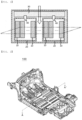
- FIG. 1 is a sectional view of a conventional battery pack.
- the conventional battery pack includes a plurality of battery cells 10, a module case 20 configured to receive the plurality of battery cells 10, a fire extinguishing material tank 30 located at an upper surface of the module case 20, and a nozzle 40 located at a lower surface of the fire extinguishing material tank 30.
- the nozzle 40 is required to extinguish fire, whereby the volume and weight of the battery pack are increased, and therefore energy density of the battery pack is decreased.
- the conventional fire extinguishing material tank 30 stores only the fire extinguishing material, which is supplied when an event occurs, and therefore a heat sink must be further provided in order to dissipate heat generated in the battery pack.
- Patent Document 1 Japanese Patent Application Publication No. 2012-252909
- the present invention has been made in view of the above problems, and it is an object of the present invention to provide an underbody for electric vehicles having a water tank configured to perform the function of a heat sink in a normal state and to be used for fire extinguishment when an event occurs in a battery cell.
- an underbody for electric vehicles includes a receiving portion (110) depressed upwards by a predetermined depth, the receiving portion being configured to receive a battery pack (200), wherein a first water tank (120) is mounted in an upper part of the receiving portion (110).
- the first water tank (120) may be integrally mounted to the underbody.
- a battery pack (200) including at least one battery module (210) may be located under the first water tank (120).
- the first water tank (120) may include an upper body (121), a lower body (122) provided with a through-hole (122') having a predetermined shape, and a sealing member (123) provided in the through-hole (122'), and the sealing member (123) includes a material configured to be melted or broken when heated to a predetermined temperature.
- the at least one battery module (210) may include a module case (211) and at least one battery cell (212), and the module case (211) may have a shape in which a part of the module case is open.
- the module case (211) may include a pair of side plates (211(a)) located respectively at opposite sides of a battery cell stack constituted by the at least one battery cell (212) and at least one strap (211(c)) configured to fix the pair of side plates (211(a)) to each other, and each of the pair of side plates (211(a)) may be provided with a wing portion (211(b)) configured to be fixed to a predetermined region of the underbody by bolting or welding.
- the module case (211) may include a pair of side plates (211(a)) located respectively at opposite sides of a battery cell stack constituted by the at least one battery cell (212) and a lower plate and an upper plate (211(d)) configured to connect the pair of side plates (211(a)) to each other, each of the pair of side plates (211(a)) may be provided with a wing portion (211(b)) configured to be fixed to a predetermined region of the underbody by bolting or welding, and the upper plate (211(d)) may be provided with at least one through-hole (211').
- a thermally conductive adhesive member (140) may be located between the first water tank (120) and the battery pack (200).
- a first shock-absorbing pad (130) may be located between the first water tank (120) and the battery pack (200).
- the underbody for electric vehicles according to the present invention may further include a cover member (180) configured to open or close the receiving portion (110).
- a second water tank (170) may be located between the battery pack (200) and the cover member (180).
- a thermally conductive adhesive member (140) may be located between the battery pack (200) and the second water tank (170).
- the second water tank (170) may be a heat sink.
- the first water tank (120) may be a heat sink.
- the present invention provides an electric vehicle including the underbody for vehicles.
- an underbody for electric vehicles having a water tank according to the present invention has both a function of cooling a battery pack and a fire extinguishment function, whereby it is possible to increase energy density.
- the water tank is integrally mounted to the underbody, whereby it is possible to omit a manufacturing process of mounting a heat sink to the underbody for vehicles.
- the water tank is located above the battery pack, whereby it is possible to easily repair or replace electric parts of a battery module or the battery pack.
- FIG. 2 is a perspective view of an underbody for vehicles according to a first preferred embodiment of the present invention
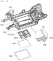
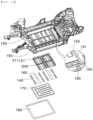
- FIG. 3 is an exploded perspective view of the underbody for vehicles according to the first preferred embodiment of the present invention
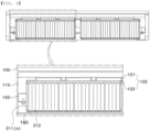
- FIG. 4 is a sectional view taken along line A-A' of FIG. 2
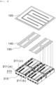
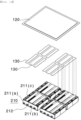
- FIG. 5 is an exploded perspective view illustrating a coupling structure between a first water tank according to a first preferred embodiment of the present invention and a battery pack.
- the underbody 100 for vehicles according to the first embodiment of the present invention is provided with a receiving portion 110 depressed by a predetermined depth in an upward direction, i.e. in a direction toward an indoor space of a vehicle, and a first water tank 120 and a battery pack 200 are mounted in the receiving portion 110.
- the first water tank 120 and the battery pack 200 are sequentially located in the receiving portion 110 of the underbody 100 for vehicles from above, and at least one of a first shock-absorbing pad 130 and a thermally conductive adhesive member 140 may be interposed between the first water tank 120 and the battery pack 200.
- the first water tank 120 may be a heat sink configured to dissipate heat generated in the battery pack 200, and it is preferable for the first water tank 120 to be integrally mounted to the underbody 100 for vehicles.
- a heat sink is mounted in a battery module or a battery pack in order to dissipate heat generated in a battery cell.
- a cover member 180 is located under the battery pack 200, and it is preferable for a second shock-absorbing pad 160 to be further provided between the battery pack 200 and the cover member 180.
- the first shock-absorbing pad 130 which is located between the first water tank 120 and the battery pack 200
- the second shock-absorbing pad 160 which is interposed between the battery pack 200 and the cover member 180
- each of the shock-absorbing pads may be made of a material that has predetermined elasticity so as to be increased and decreased in volume, such as sponge.
- the cover member 180 which has an approximately flat shape, is configured to open and close the receiving portion 110 formed in the underbody 100 for vehicles, and is fixed to a plurality of second fixing members 190 provided along an edge of an opening of the receiving portion 110 by screw fastening, etc.
- the thermally conductive adhesive member 140 is located between the first water tank 120 and the battery pack 200 in order to fix the first water tank 120 and the battery pack 200 to each other and to allow easy heat exchange between the first water tank 120 and the battery pack 200.
- the material for the thermally conductive adhesive member 140 is not particularly restricted as long as the material exhibits thermal conductivity and heat resistance.
- the thermally conductive adhesive member may be made of at least one of curable grease and epoxy-based adhesive glue.
- first shock-absorbing pad 130 and the thermally conductive adhesive member 140 are shown as being simultaneously interposed between the first water tank 120 and the battery pack 200 in FIG. 5 , only one thereof may be provided.
- the battery pack 200 is primarily fixed to the underbody 100 for vehicles. That is, a quadrangular or H-beam-shaped first fixing member 150 is provided at opposite edges of the underbody 100 for vehicles and in the middle of the receiving portion 110, and the battery pack 200 is coupled to the first fixing member 150 through a known fastening means, such as screw coupling.
- the battery pack 200 which is located under the first water tank 120 in a state of being mounted in the receiving portion 110 of the underbody 100 for vehicles, includes at least one battery module 210.
- the battery module 210 includes a module case 211 open at a part thereof and a plurality of battery cells 212 received in the module case 211.
- the module case 211 includes a pair of side plates 211(a) located respectively at opposite sides of a battery cell stack configured to have a structure in which the several battery cells 212 are stacked side by side in a vertical or horizontal direction, at least one strap 211(c) configured to fix the pair of side plates 211(a) to each other, and a lower plate (not shown).
- the at least one strap 211(c) it is preferable for the at least one strap 211(c) not to completely cover an upper surface of the module case 211.
- the reason for this is that it is necessary for air or liquid to easily pass through the interior of the module case 211.
- At least one of the first shock-absorbing pad 130 and the thermally conductive adhesive member 140 is located at the strap 211(c) located at an upper side of the battery cell stack.
- Each of the pair of side plates 211(a) is provided with a wing portion 211(b) protruding outwards by a predetermined length.
- the wing portion 211(b) is brought into contact with the first fixing member 150 provided at the underbody 100 for vehicles, and is fastened thereto using a known fastening means, such as a bolt, whereby the battery module 210 may be stably fixed in the receiving portion 110.
- Each of the battery cells 212 includes a cell assembly, a cell case configured to receive the cell assembly, and a pair of leads.
- a battery pack is shown as including four battery modules in FIGS. 3 and 5 , this is merely an example and the number of battery modules may be changed without limit.
- the cell assembly may be a jelly-roll type cell assembly, which is configured to have a structure in which a long sheet type positive electrode and a long sheet type negative electrode are wound in the state in which a separator is interposed therebetween, a stacked type cell assembly including unit cells, each of which is configured to have a structure in which a rectangular positive electrode and a rectangular negative electrode are stacked in the state in which a separator is interposed therebetween, a stacked and folded type cell assembly, which is configured to have a structure in which unit cells are wound using a long separation film, or a laminated and stacked type cell assembly, which is configured to have a structure in which unit cells are stacked in the state in which a separator is interposed therebetween and are then attached to each other.
- the present invention is not limited thereto.
- the cell assembly is received in the cell case, and the cell case is generally configured to have a laminate sheet structure including an inner layer, a metal layer, and an outer layer.
- the inner layer is disposed in direct contact with the cell assembly, and therefore the inner layer must exhibit high insulation properties and high resistance to an electrolytic solution.
- the inner layer must exhibit high sealability in order to hermetically seal the cell case from the outside, i.e. a thermally-bonded sealed portion between inner layers must exhibit excellent thermal bonding strength.
- the inner layer may be made of a material selected from among a polyolefin-based resin, such as polypropylene, polyethylene, polyethylene acrylate, or polybutylene, a polyurethane resin, and a polyimide resin, which exhibit excellent chemical resistance and high sealability.
- a polyolefin-based resin such as polypropylene, polyethylene, polyethylene acrylate, or polybutylene, a polyurethane resin, and a polyimide resin, which exhibit excellent chemical resistance and high sealability.
- polypropylene which exhibits excellent mechanical-physical properties, such as tensile strength, rigidity, surface hardness, and impact resistance, and excellent chemical resistance, is the most preferably used.
- the metal layer which is disposed so as to abut the inner layer, corresponds to a barrier layer configured to prevent moisture or various kinds of gas from permeating into the battery from the outside.
- An aluminum thin film which is lightweight and easily shapeable, may be used as a preferred material for the metal layer.
- the outer layer is provided on the other surface of the metal layer.
- the outer layer may be made of a heat-resistant polymer that exhibits excellent tensile strength, resistance to moisture permeation, and resistance to air transmission such that the outer layer exhibits high heat resistance and chemical resistance while protecting the cell assembly.
- the outer layer may be made of nylon or polyethylene terephthalate.
- the present invention is not limited thereto.
- the leads which include a positive electrode lead and a negative electrode lead, are electrically connected to a positive electrode tab and a negative electrode tab of the cell assembly and are exposed outwards from the case.
- the battery cell corresponds to generally known constructions, and therefore a more detailed description thereof will be omitted.
- FIG. 6 is an exploded perspective view of the first water tank according to the first preferred embodiment of the present invention.
- the first water tank 120 according to the first preferred embodiment of the present invention includes an upper body 121 having a predetermined height and a lower body 122 coupled to a lower side of the upper body 121 to define a predetermined space necessary for water to circulate.
- the water tank 120 may be provided with a water circulation channel. Although not shown in the figure, the water tank may be further provided with a water inlet introduction port and a water discharge port such that the water tank can be maintained at a predetermined temperature.
- FIG. 7 is a perspective view of a modified battery module according to a first preferred embodiment of the present invention.
- a module case 211 of the modified battery module 210 includes a pair of side plates 211(a) located at opposite sides of a battery cell stack constituted by battery cells 212, a wing portion 211(b) protruding outwards from each of the pair of side plates 211(a) by a predetermined length, and an upper plate 211(d) and a lower surface (not shown) configured to connect the pair of side plates 211(a) to each other.
- one or more through-holes 211' spaced apart from each other by a predetermined distance to be formed in the upper plate 211(d) such that air or liquid can easily pass through the interior of the module case 211.
- FIG. 8 is an exploded perspective view of an underbody for vehicles according to a second preferred embodiment of the present invention
- FIG. 9 is a sectional view of the underbody for vehicles according to the second preferred embodiment of the present invention
- FIG. 10 is an exploded perspective view of a first water tank according to a second preferred embodiment of the present invention.
- the underbody 100 for vehicles according to the second preferred embodiment of the present invention is identical in construction to the underbody 100 for vehicles according to the first preferred embodiment of the present invention described with reference to FIGS. 2 to 7 except for the first water tank, and therefore a description of the same construction will be omitted.
- the first water tank 120 includes an upper body 121 having a predetermined height and a lower body 122 coupled to a lower side of the upper body 121 to define a predetermined space necessary for water to circulate.
- the lower body 122 is provided with at least one bar-shaped through-hole 122', and a sealing member 123, which is made of a material that is melted or broken when heated to a predetermined temperature, for example a resin having a melting point of 200°C or lower, such as polyethylene or polypropylene, is mounted in the through-hole 122'.
- a sealing member 123 which is made of a material that is melted or broken when heated to a predetermined temperature, for example a resin having a melting point of 200°C or lower, such as polyethylene or polypropylene, is mounted in the through-hole 122'.
- the sealing member 123 When the sealing member 123 is provided at a predetermined region of the lower body 122 of the first water tank 120, as in the second embodiment, the sealing member performs the function of a heat sink during normal operation of the battery pack. However, when an event occurs in a specific battery cell, for example when a high-temperature gas is generated in the battery cell, sparks are generated in the battery cell, or fire breaks out in the battery cell, the sealing member 123 is melted or broken. At this time, water in the first water tank 120 is directly introduced into the battery module or the battery pack through the through-hole 122', whereby it is possible to prevent secondary damage, such as explosion.
- FIG. 11 is a sectional view of an underbody for vehicles according to a third preferred embodiment of the present invention
- FIG. 12 is an exploded perspective view illustrating a coupling structure between a first water tank according to a third preferred embodiment of the present invention and a battery pack
- FIG. 13 is an exploded perspective view of the first water tank according to the third preferred embodiment of the present invention.
- the underbody 100 for vehicles according to the third preferred embodiment of the present invention is identical in construction to the underbody for vehicles described with reference to FIGS. 8 to 10 except for the first water tank 120 according to the second embodiment.
- the first water tank 120 according to the second embodiment is configured such that the channel is provided in the upper body 121, whereas the upper body 121 may be provided with no channel in the third embodiment.
- FIG. 14 is an exploded perspective view of an underbody for electric vehicles according to a fourth preferred embodiment of the present invention
- FIG. 15 is a sectional view of the underbody for electric vehicles according to the fourth preferred embodiment of the present invention.
- the underbody 100 for electric vehicles further includes a second water tank 170 disposed between the first water tank 120 and the cover member 180 according to the second embodiment or the third embodiment described with reference to FIGS. 8 to 12 .
- the second water tank 170 is a heat sink, and it is more preferable for the first water tank 120 to be a tank for fire extinguishment and for the second water tank 170 to perform the function of a heat sink.
- the second water tank 170 functions as a heat sink, includes an upper body and a lower body, as shown in FIG. 6 , and it is preferable for a channel to be formed in each body.
- a thermally conductive adhesive member 140 and a second shock-absorbing pad 160 may be interposed between the battery pack 200 and the second water tank 170.
- the thermally conductive adhesive member 140 is the same as above, and the second shock-absorbing pad 160 is identical in construction and function to the first shock-absorbing pad 130, and therefore a duplicate description thereof will be omitted.
- the present invention may provide an electric vehicle including the underbody 100 for vehicles.
- the electric vehicle means a transportation means configured to move through a reaction caused by friction between wheels connected to a vehicle body so as to be driven using power including electricity and the surface of a road, and may encompass all vehicles each having an underbody and capable of being driven by electricity, such as a passenger car, a van, a truck, and a special car, including a tractor and a cultivator.
Landscapes
- Chemical & Material Sciences (AREA)
- Engineering & Computer Science (AREA)
- Chemical Kinetics & Catalysis (AREA)
- General Chemical & Material Sciences (AREA)
- Electrochemistry (AREA)
- Manufacturing & Machinery (AREA)
- Mechanical Engineering (AREA)
- Transportation (AREA)
- Combustion & Propulsion (AREA)
- Health & Medical Sciences (AREA)
- Public Health (AREA)
- Business, Economics & Management (AREA)
- Emergency Management (AREA)
- Aviation & Aerospace Engineering (AREA)
- Battery Mounting, Suspending (AREA)
- Body Structure For Vehicles (AREA)
- Secondary Cells (AREA)
Applications Claiming Priority (4)
| Application Number | Priority Date | Filing Date | Title |
|---|---|---|---|
| KR20210022220 | 2021-02-19 | ||
| KR20210022219 | 2021-02-19 | ||
| KR1020220004292A KR102958746B1 (ko) | 2021-02-19 | 2022-01-11 | 워터탱크가 구비된 전기차용 언더 바디 |
| PCT/KR2022/001784 WO2022177210A1 (fr) | 2021-02-19 | 2022-02-04 | Dessous de caisse de véhicule électrique comportant un réservoir d'eau |
Publications (3)
| Publication Number | Publication Date |
|---|---|
| EP4166428A1 true EP4166428A1 (fr) | 2023-04-19 |
| EP4166428A4 EP4166428A4 (fr) | 2024-03-27 |
| EP4166428B1 EP4166428B1 (fr) | 2026-04-01 |
Family
ID=82930926
Family Applications (1)
| Application Number | Title | Priority Date | Filing Date |
|---|---|---|---|
| EP22756411.9A Active EP4166428B1 (fr) | 2021-02-19 | 2022-02-04 | Dessous de caisse de véhicule électrique comportant un réservoir d'eau |
Country Status (5)
| Country | Link |
|---|---|
| US (1) | US20230253674A1 (fr) |
| EP (1) | EP4166428B1 (fr) |
| JP (1) | JP7562210B2 (fr) |
| CN (1) | CN115812055A (fr) |
| WO (1) | WO2022177210A1 (fr) |
Cited By (1)
| Publication number | Priority date | Publication date | Assignee | Title |
|---|---|---|---|---|
| EP4675768A1 (fr) * | 2024-07-03 | 2026-01-07 | Volvo Truck Corporation | Réservoir de liquide pour gestion d'emballement thermique |
Family Cites Families (16)
| Publication number | Priority date | Publication date | Assignee | Title |
|---|---|---|---|---|
| JP5194687B2 (ja) | 2007-09-28 | 2013-05-08 | 三菱自動車工業株式会社 | バッテリユニット |
| EP2416439B1 (fr) * | 2009-04-01 | 2015-07-29 | LG Chem, Ltd. | Module de batterie comportant une radiation thermique excellente et bloc-batteries celui-ci |
| KR101090717B1 (ko) * | 2009-09-07 | 2011-12-08 | 현대자동차주식회사 | 배터리 팩 |
| JP5760713B2 (ja) * | 2011-06-03 | 2015-08-12 | トヨタ自動車株式会社 | 電池パック |
| US9054402B1 (en) * | 2013-11-19 | 2015-06-09 | Atieva, Inc. | Electric vehicle battery pack protection system |
| WO2015120742A1 (fr) * | 2014-02-13 | 2015-08-20 | 浙江吉利汽车研究院有限公司 | Système de gestion thermique et d'extinction d'incendie automatique de batterie de véhicule automobile |
| JP6706294B2 (ja) * | 2018-08-31 | 2020-06-03 | 本田技研工業株式会社 | バッテリパックの冷却構造 |
| DE102018131374B4 (de) * | 2018-12-07 | 2025-07-17 | Benteler Automobiltechnik Gmbh | Modular aufgebauter Batterieträger |
| KR102512593B1 (ko) * | 2019-02-26 | 2023-03-27 | 한국자동차연구원 | 배터리 모듈 |
| JP7172882B2 (ja) * | 2019-06-28 | 2022-11-16 | トヨタ自動車株式会社 | 車両下部構造 |
| KR102791885B1 (ko) | 2019-07-08 | 2025-04-04 | 주식회사 엘지에너지솔루션 | 열 폭주 현상 발생 시 냉각수가 내부로 투입될 수 있는 구조를 갖는 배터리 모듈, 이를 포함하는 배터리 팩 및 에너지저장장치 |
| KR102705400B1 (ko) * | 2019-08-07 | 2024-09-12 | 주식회사 엘지에너지솔루션 | 자동차용 언더 바디 |
| KR102271612B1 (ko) | 2019-08-19 | 2021-07-02 | 숙명여자대학교 산학협력단 | 전기자동차용 배터리 장치 및 이를 구비하는 전기자동차 |
| KR102699010B1 (ko) | 2019-08-19 | 2024-08-26 | 현대자동차주식회사 | 차량의 통합 열관리 모듈 |
| CN212085172U (zh) * | 2020-04-21 | 2020-12-04 | 重庆金康动力新能源有限公司 | 一种电池包 |
| KR20220004292A (ko) | 2020-07-03 | 2022-01-11 | 한국전력공사 | 전력설비의 부분방전을 검출하는 방법 및 그 시스템 |
-
2022
- 2022-02-04 WO PCT/KR2022/001784 patent/WO2022177210A1/fr not_active Ceased
- 2022-02-04 CN CN202280005525.7A patent/CN115812055A/zh active Pending
- 2022-02-04 US US18/015,656 patent/US20230253674A1/en active Pending
- 2022-02-04 EP EP22756411.9A patent/EP4166428B1/fr active Active
- 2022-02-04 JP JP2023501657A patent/JP7562210B2/ja active Active
Cited By (1)
| Publication number | Priority date | Publication date | Assignee | Title |
|---|---|---|---|---|
| EP4675768A1 (fr) * | 2024-07-03 | 2026-01-07 | Volvo Truck Corporation | Réservoir de liquide pour gestion d'emballement thermique |
Also Published As
| Publication number | Publication date |
|---|---|
| US20230253674A1 (en) | 2023-08-10 |
| WO2022177210A1 (fr) | 2022-08-25 |
| CN115812055A (zh) | 2023-03-17 |
| JP7562210B2 (ja) | 2024-10-07 |
| JP2023534003A (ja) | 2023-08-07 |
| EP4166428A4 (fr) | 2024-03-27 |
| EP4166428B1 (fr) | 2026-04-01 |
Similar Documents
| Publication | Publication Date | Title |
|---|---|---|
| EP4191750B1 (fr) | Bloc-batterie ayant des performances de refroidissement améliorées et dispositif le comprenant | |
| KR20200078344A (ko) | 차량용 전지 팩 | |
| US20220263174A1 (en) | Battery module capable of preventing movement of gas to adjacent module | |
| EP4071892B1 (fr) | Bloc-batterie ayant une unité de refroidissement à l'extérieur du boîtier | |
| US20230128563A1 (en) | Battery module having pocket capable of capturing flare and spark ejected during swelling | |
| JP2024506457A (ja) | 安全性が向上したパウチ型電池セル及びこれを含む電池モジュール | |
| EP4166428A1 (fr) | Dessous de caisse de véhicule électrique comportant un réservoir d'eau | |
| EP4539227A1 (fr) | Bloc-batterie et dispositif le comprenant | |
| EP4195384A1 (fr) | Bloc-batterie et dispositif le comprenant | |
| KR102958746B1 (ko) | 워터탱크가 구비된 전기차용 언더 바디 | |
| EP4087036A1 (fr) | Module de batterie et bloc-batterie le comprenant | |
| EP4683082A1 (fr) | Bloc-batterie et dispositif le comprenant | |
| US12597654B2 (en) | Battery module having bent trap portion and battery pack including the same | |
| EP4425677A1 (fr) | Bloc-batterie et dispositif le comprenant | |
| EP4525150A1 (fr) | Bloc-batterie et véhicule le comprenant | |
| KR20220119313A (ko) | 워터탱크가 구비된 전기차용 언더 바디 | |
| KR20250037998A (ko) | 전지팩 및 이를 포함하는 디바이스 | |
| KR20250147389A (ko) | 향상된 냉각성능을 가지는 배터리 팩 | |
| KR20250147380A (ko) | 향상된 냉각성능을 가지는 배터리 팩 | |
| KR20250135968A (ko) | 배터리 모듈을 포함하는 에너지 저장 장치 | |
| KR20260059838A (ko) | 배터리 모듈 및 이를 포함하는 배터리 팩 | |
| KR20260012521A (ko) | 배터리용 벤팅 장치 및 이를 포함하는 배터리 팩 | |
| KR20250099863A (ko) | 배터리 모듈 및 이를 포함하는 배터리 팩 | |
| KR20260018637A (ko) | 배터리 팩 및 이를 포함하는 자동차 | |
| KR20250067716A (ko) | 전지팩 및 이를 포함하는 디바이스 |
Legal Events
| Date | Code | Title | Description |
|---|---|---|---|
| STAA | Information on the status of an ep patent application or granted ep patent |
Free format text: STATUS: THE INTERNATIONAL PUBLICATION HAS BEEN MADE |
|
| PUAI | Public reference made under article 153(3) epc to a published international application that has entered the european phase |
Free format text: ORIGINAL CODE: 0009012 |
|
| STAA | Information on the status of an ep patent application or granted ep patent |
Free format text: STATUS: REQUEST FOR EXAMINATION WAS MADE |
|
| 17P | Request for examination filed |
Effective date: 20221227 |
|
| AK | Designated contracting states |
Kind code of ref document: A1 Designated state(s): AL AT BE BG CH CY CZ DE DK EE ES FI FR GB GR HR HU IE IS IT LI LT LU LV MC MK MT NL NO PL PT RO RS SE SI SK SM TR |
|
| A4 | Supplementary search report drawn up and despatched |
Effective date: 20240227 |
|
| RIC1 | Information provided on ipc code assigned before grant |
Ipc: B60K 11/02 20060101ALI20240221BHEP Ipc: H01M 10/613 20140101ALI20240221BHEP Ipc: H01M 10/625 20140101ALI20240221BHEP Ipc: H01M 10/6551 20140101ALI20240221BHEP Ipc: H01M 50/249 20210101ALI20240221BHEP Ipc: H01M 50/24 20210101ALI20240221BHEP Ipc: A62C 99/00 20100101ALI20240221BHEP Ipc: A62C 35/10 20060101ALI20240221BHEP Ipc: A62C 3/07 20060101ALI20240221BHEP Ipc: B62D 25/20 20060101AFI20240221BHEP |
|
| DAV | Request for validation of the european patent (deleted) | ||
| DAX | Request for extension of the european patent (deleted) | ||
| STAA | Information on the status of an ep patent application or granted ep patent |
Free format text: STATUS: EXAMINATION IS IN PROGRESS |
|
| 17Q | First examination report despatched |
Effective date: 20250514 |
|
| GRAP | Despatch of communication of intention to grant a patent |
Free format text: ORIGINAL CODE: EPIDOSNIGR1 |
|
| STAA | Information on the status of an ep patent application or granted ep patent |
Free format text: STATUS: GRANT OF PATENT IS INTENDED |
|
| INTG | Intention to grant announced |
Effective date: 20250922 |
|
| GRAS | Grant fee paid |
Free format text: ORIGINAL CODE: EPIDOSNIGR3 |
|
| GRAA | (expected) grant |
Free format text: ORIGINAL CODE: 0009210 |
|
| STAA | Information on the status of an ep patent application or granted ep patent |
Free format text: STATUS: THE PATENT HAS BEEN GRANTED |
|
| P01 | Opt-out of the competence of the unified patent court (upc) registered |
Free format text: CASE NUMBER: UPC_APP_0005063_4166428/2026 Effective date: 20260211 |
|
| AK | Designated contracting states |
Kind code of ref document: B1 Designated state(s): AL AT BE BG CH CY CZ DE DK EE ES FI FR GB GR HR HU IE IS IT LI LT LU LV MC MK MT NL NO PL PT RO RS SE SI SK SM TR |
|
| REG | Reference to a national code |
Ref country code: CH Ref legal event code: F10 Free format text: ST27 STATUS EVENT CODE: U-0-0-F10-F00 (AS PROVIDED BY THE NATIONAL OFFICE) Effective date: 20260401 Ref country code: GB Ref legal event code: FG4D |
|
| REG | Reference to a national code |
Ref country code: DE Ref legal event code: R096 Ref document number: 602022033555 Country of ref document: DE |
|
| REG | Reference to a national code |
Ref country code: IE Ref legal event code: FG4D |