EP4166524B1 - Ofen zum erhitzen eines dentalobjektes - Google Patents
Ofen zum erhitzen eines dentalobjektes Download PDFInfo
- Publication number
- EP4166524B1 EP4166524B1 EP21202639.7A EP21202639A EP4166524B1 EP 4166524 B1 EP4166524 B1 EP 4166524B1 EP 21202639 A EP21202639 A EP 21202639A EP 4166524 B1 EP4166524 B1 EP 4166524B1
- Authority
- EP
- European Patent Office
- Prior art keywords
- dental object
- radiation source
- heating
- furnace
- chamber
- Prior art date
- Legal status (The legal status is an assumption and is not a legal conclusion. Google has not performed a legal analysis and makes no representation as to the accuracy of the status listed.)
- Active
Links
Images

Classifications
-
- C—CHEMISTRY; METALLURGY
- C03—GLASS; MINERAL OR SLAG WOOL
- C03C—CHEMICAL COMPOSITION OF GLASSES, GLAZES OR VITREOUS ENAMELS; SURFACE TREATMENT OF GLASS; SURFACE TREATMENT OF FIBRES OR FILAMENTS MADE FROM GLASS, MINERALS OR SLAGS; JOINING GLASS TO GLASS OR OTHER MATERIALS
- C03C23/00—Other surface treatment of glass not in the form of fibres or filaments
- C03C23/0005—Other surface treatment of glass not in the form of fibres or filaments by irradiation
- C03C23/002—Other surface treatment of glass not in the form of fibres or filaments by irradiation by ultraviolet light
-
- F—MECHANICAL ENGINEERING; LIGHTING; HEATING; WEAPONS; BLASTING
- F27—FURNACES; KILNS; OVENS; RETORTS
- F27B—FURNACES, KILNS, OVENS OR RETORTS IN GENERAL; OPEN SINTERING OR LIKE APPARATUS
- F27B17/00—Furnaces of a kind not covered by any of groups F27B1/00 - F27B15/00
- F27B17/02—Furnaces of a kind not covered by any of groups F27B1/00 - F27B15/00 specially designed for laboratory use
- F27B17/025—Furnaces of a kind not covered by any of groups F27B1/00 - F27B15/00 specially designed for laboratory use for dental workpieces
-
- A—HUMAN NECESSITIES
- A61—MEDICAL OR VETERINARY SCIENCE; HYGIENE
- A61C—DENTISTRY; APPARATUS OR METHODS FOR ORAL OR DENTAL HYGIENE
- A61C13/00—Dental prostheses; Making same
- A61C13/0003—Making bridge-work, inlays, implants or the like
-
- A—HUMAN NECESSITIES
- A61—MEDICAL OR VETERINARY SCIENCE; HYGIENE
- A61C—DENTISTRY; APPARATUS OR METHODS FOR ORAL OR DENTAL HYGIENE
- A61C13/00—Dental prostheses; Making same
- A61C13/08—Artificial teeth; Making same
- A61C13/082—Cosmetic aspects, e.g. inlays; Determination of the colour
-
- A—HUMAN NECESSITIES
- A61—MEDICAL OR VETERINARY SCIENCE; HYGIENE
- A61C—DENTISTRY; APPARATUS OR METHODS FOR ORAL OR DENTAL HYGIENE
- A61C13/00—Dental prostheses; Making same
- A61C13/12—Tools for fastening artificial teeth; Holders, clamps, or stands for artificial teeth
- A61C13/14—Vulcanising devices for artificial teeth
-
- A—HUMAN NECESSITIES
- A61—MEDICAL OR VETERINARY SCIENCE; HYGIENE
- A61C—DENTISTRY; APPARATUS OR METHODS FOR ORAL OR DENTAL HYGIENE
- A61C13/00—Dental prostheses; Making same
- A61C13/20—Methods or devices for soldering, casting, moulding or melting
-
- A—HUMAN NECESSITIES
- A61—MEDICAL OR VETERINARY SCIENCE; HYGIENE
- A61C—DENTISTRY; APPARATUS OR METHODS FOR ORAL OR DENTAL HYGIENE
- A61C19/00—Dental auxiliary appliances
- A61C19/003—Apparatus for curing resins by radiation
-
- A—HUMAN NECESSITIES
- A61—MEDICAL OR VETERINARY SCIENCE; HYGIENE
- A61C—DENTISTRY; APPARATUS OR METHODS FOR ORAL OR DENTAL HYGIENE
- A61C5/00—Filling or capping teeth
- A61C5/70—Tooth crowns; Making thereof
-
- A—HUMAN NECESSITIES
- A61—MEDICAL OR VETERINARY SCIENCE; HYGIENE
- A61C—DENTISTRY; APPARATUS OR METHODS FOR ORAL OR DENTAL HYGIENE
- A61C8/00—Means to be fixed to the jaw-bone for consolidating natural teeth or for fixing dental prostheses thereon; Dental implants; Implanting tools
- A61C8/0048—Connecting the upper structure to the implant, e.g. bridging bars
- A61C8/005—Connecting devices for joining an upper structure with an implant member, e.g. spacers
-
- F—MECHANICAL ENGINEERING; LIGHTING; HEATING; WEAPONS; BLASTING
- F27—FURNACES; KILNS; OVENS; RETORTS
- F27D—DETAILS OR ACCESSORIES OF FURNACES, KILNS, OVENS OR RETORTS, IN SO FAR AS THEY ARE OF KINDS OCCURRING IN MORE THAN ONE KIND OF FURNACE
- F27D21/00—Arrangement of monitoring devices; Arrangement of safety devices
-
- F—MECHANICAL ENGINEERING; LIGHTING; HEATING; WEAPONS; BLASTING
- F27—FURNACES; KILNS; OVENS; RETORTS
- F27D—DETAILS OR ACCESSORIES OF FURNACES, KILNS, OVENS OR RETORTS, IN SO FAR AS THEY ARE OF KINDS OCCURRING IN MORE THAN ONE KIND OF FURNACE
- F27D99/00—Subject matter not provided for in other groups of this subclass
- F27D99/0001—Heating elements or systems
- F27D99/0006—Electric heating elements or system
-
- A—HUMAN NECESSITIES
- A61—MEDICAL OR VETERINARY SCIENCE; HYGIENE
- A61C—DENTISTRY; APPARATUS OR METHODS FOR ORAL OR DENTAL HYGIENE
- A61C2201/00—Material properties
- A61C2201/002—Material properties using colour effect, e.g. for identification purposes
-
- F—MECHANICAL ENGINEERING; LIGHTING; HEATING; WEAPONS; BLASTING
- F27—FURNACES; KILNS; OVENS; RETORTS
- F27D—DETAILS OR ACCESSORIES OF FURNACES, KILNS, OVENS OR RETORTS, IN SO FAR AS THEY ARE OF KINDS OCCURRING IN MORE THAN ONE KIND OF FURNACE
- F27D99/00—Subject matter not provided for in other groups of this subclass
- F27D99/0001—Heating elements or systems
- F27D99/0006—Electric heating elements or system
- F27D2099/0026—Electric heating elements or system with a generator of electromagnetic radiations
Definitions
- the present invention relates to an oven for heating a dental object and a method for heating the dental object.
- Polychrome glasses and glass ceramics can be colored by exposure together with a thermal treatment, such as a quartz glass, a quartz glass ceramic, a lithium aluminosilicate glass, a lithium aluminosilicate glass ceramic, a lithium silicate glass or a lithium silicate glass ceramic.
- a thermal treatment such as a quartz glass, a quartz glass ceramic, a lithium aluminosilicate glass, a lithium aluminosilicate glass ceramic, a lithium silicate glass or a lithium silicate glass ceramic.
- the exposure here usually takes place using UV radiation. After exposure, the different color effects are mainly achieved through heat treatment.
- the polychrome glasses and glass ceramics include, for example, an oxidizable component and a reducible coloring component.
- the oxidizable component is a component that can be oxidized by irradiation or stimulated to release electrons. Oxidizable components include, for example, cerium ions, europium ions, copper ions and mixtures thereof.
- the reducible coloring component is, for example, a component that can be reduced to produce a color change.
- Preferred reducible coloring components are cations of metals such as silver, gold, copper or combinations thereof.
- the publication WO 2011/113568 A1 relates to a method for treating a dental implant component.
- the publication JP 3 203603 U relates to an ultraviolet radiation emitting device used as a cleaning device for cleaning bacteria from medical instruments, such as dental implants
- the publication WO 2004/051716 A1 relates to an exposure apparatus for forming a thin pattern on an electronic device, such as for etching conductive lines of a semiconductor element.
- the technical problem is solved by an oven for heating a dental object, with a chamber for receiving the dental object; a radiation source for emitting radiation with a wavelength smaller than 350 nm into the chamber; and a heater for heating the dental object in the chamber.
- the heating device is designed to heat the dental object to a temperature of up to 1200 ° C.
- the heating device can be designed to heat the dental object in a temperature range between 25°C and 1200°C, between 25°C and 1100°C or between 25°C and 1000°C. This achieves, for example, the technical advantage that the dental object can be heated to suitable temperatures for coloring.
- the oven comprises a control device for controlling the radiation source and/or the heating device.
- a control device for controlling the radiation source and/or the heating device.
- control device comprises a trained algorithm for controlling the radiation source and/or the heating device.
- the algorithm can be a machine learning algorithm. This achieves, for example, the technical advantage that the coloring of the dental object can be automated based on training data.
- control device is designed to temporally control an intensity of the radiation source and/or a temperature of the heating device.
- the control device can, for example, execute predetermined intensity and temperature curves. This achieves, for example, the technical advantage that a finely tuned exposure and thermal treatment can be carried out in order to obtain a desired color of the dental object.
- control device is designed to activate the radiation source and heating device simultaneously or with a time delay. This achieves, for example, the technical advantage that the exposure can be carried out before or during the thermal treatment.
- the oven comprises an electronic camera for detecting a color value of the dental object. This achieves, for example, the technical advantage that the color value of the dental object can be monitored during heating.
- the oven is designed to stop heating the dental object when the dental object has reached a predetermined color value. This achieves, for example, the technical advantage that the specified color value can be achieved precisely.
- the oven comprises a cooling device for cooling the heated dental object. This achieves, for example, the technical advantage that an achieved color value can be stabilized and recoloring of the dental object is prevented.
- the heating device is formed by an infrared radiation source, a laser radiation source, a microwave radiation source or an induction radiation source. This achieves, for example, the technical advantage that particularly suitable heating devices are used to heat the dental object.
- the oven comprises a movement device for moving the dental object in front of the heating device and/or the radiation source. This achieves, for example, the technical advantage that the thermal treatment and the radiation can be directed to different areas of the dental object.
- the technical problem is solved by a method for heating a dental object, with which Steps of receiving the dental object in a chamber; emitting radiation having a wavelength smaller than 350 nm into the chamber by a radiation source; and heating the dental object in the chamber by a heater.
- the process achieves the same technical advantages as the oven according to the first aspect.
- an intensity of the radiation source and a temperature of the heating device are time-controlled. This also achieves, for example, the technical advantage that a finely tuned exposure and thermal treatment can be carried out in order to obtain a desired color of the dental object.
- the radiation source and heating device are activated simultaneously or with a time delay. This also achieves, for example, the technical advantage that the exposure can be carried out before or during the thermal treatment.
- a color value of the dental object is recorded by an electronic camera. This also achieves, for example, the technical advantage that the color value of the dental object can be monitored during heating.
- heating of the dental object is stopped when the dental object has reached a predetermined color value. This also creates a technical advantage, for example ensures that the specified color value can be achieved precisely.
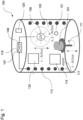
- Fig. 1 shows a schematic representation of an oven 100 for heating a dental object 101 in a chamber 103.
- the oven 100 comprises a heating device 113 for heating the dental object 101 in the chamber 103, such as a heating coil.
- the oven 100 can be operated under vacuum (adjustable oxygen partial pressure) or different atmospheres (air, inert gas) or mixtures.
- the dental object 101 is made of a polychrome glass and/or a polychrome glass ceramic, which can be colored by exposure together with a thermal treatment. After exposure, the different color effect of the dental object 101 is mainly produced via a temperature treatment.
- the dental object 101 is a dental restoration, such as a crown, a bridge, a veneer, an abutment, an inlay or an onlay.
- the heating device 113 can be provided, for example, by an infrared radiation source, a laser radiation source Microwave radiation source or an induction radiation source may be formed.
- the laser radiation source can be formed by a thermal laser or infrared laser, such as an Nd:YAG laser, an Er:YAG laser, a CO or CO2 laser.
- the heating device 113 can also be formed, for example, by an electrically operated infrared lamp, a red light lamp or a heat lamp.
- any other wavelength can also be used, such as in the visible or UV range, since only the thermal input into the dental object 101 is important for heating.
- the heat treatment can also be carried out using microwave radiation.
- the heating device 113 is capable of heating the dental object 101 to a temperature of up to 1200°C, in particular in a temperature range between 25°C and 1200°C, between 25°C and 1100°C or between 25°C and 1000 °C.
- the heating device 113 can be arranged inside or outside the chamber 103. Radiation can be guided into the chamber 103 using an optical fiber.
- the heating device 113 such as an IR laser, can also be arranged outside the chamber.
- the emitted radiation can then be scanned using a scanner (eg DMD - Digital Mirror Device) through a suitable viewing window over the dental object 101 arranged inside the chamber 103.
- a scanner eg DMD - Digital Mirror Device
- the oven 100 includes a radiation source 105.
- the radiation source 105 is used to expose the dental object 101 before or during the thermal treatment in the oven 100.
- the radiation source 105 is used to emit radiation with a wavelength that is smaller than 350 nm , into the chamber 103.
- the emitted radiation is used to expose the dental object.
- the radiation emitted from the radiation source 105 hits the dental object 101.
- the radiation stimulates electronic transitions in the dental object 101, which lead to a color change when the dental object 101 is subsequently or simultaneously heated.
- the radiation source 105 is operated electrically and is formed, for example, by a mercury vapor lamp, a quartz lamp, a black light lamp, a UV laser or a UV light-emitting diode.
- the radiation source 105 can also include an X-ray tube for generating X-rays. In this case, the radiation source 105 may emit radiation with a wavelength of 5 pm to 10 nm.
- the radiation source 105 is suitable for emitting radiation with a wavelength between 350 nm and 5 pm, preferably between 350 nm and 10 nm, or most preferably between 350 nm and 100 nm.
- a wavelength between 350 nm and 5 pm preferably between 350 nm and 10 nm, or most preferably between 350 nm and 100 nm.
- UV radiation it is also possible to expose the dental object 101 to high-energy radiation.
- high-energy radiation For example, with X-rays with a wavelength of 5 pm to 10 nm.
- radiation in the range from 100 nm to 350 nm is particularly preferred in order to stimulate electron transitions in the polychrome material.
- the oven 100 may include a UV-transparent holder on which a dental object 101 with a cavity can be placed can and which enables the dental object 101 to be illuminated on the inside.
- the chamber 103 may include a door 115 that is opened to place the dental object 101 inside. To expose the dental object 101, the door 115 is closed so that no light can escape from the chamber 103 to the outside.
- the radiation source 105 may include an electrical switch that is activated when the door 115 is opened and by which the radiation source 105 is deactivated. This achieves the technical advantage that dangerous radiation is prevented from escaping from the chamber 103.
- the radiation source 105 is arranged, for example, in a wall of the chamber 103 so that it can radiate into the interior.
- a diaphragm 121 can be arranged in front of the radiation source 105, which shields the lateral areas of the radiation, such as a pinhole diaphragm. This allows the emitted radiation to be directed to specific areas of the dental object 101.
- the oven 100 can also include a light guide with which the radiation from the radiation source 105 is brought to the dental object 101, such as a quartz glass fiber.
- the radiation source 105 can be arranged behind a special glass, such as behind a filter disk that only allows predetermined wavelength ranges to pass through.
- the oven 100 comprises an adjustment device 107.
- the adjustment device 107 can be formed by appropriate regulators with which the power of the radiation source 105 or the heating device 113 can be regulated. With this setting device 107, for example, the current or the voltage with which the Radiation source 105 or the heating device 113 is operated.
- the setting device 107 can also be implemented digitally.
- the oven 100 includes a data interface 117, via which data for controlling the intensity of the radiation source 105 or the power of the heating device 113 can be transmitted from an external device, such as a WLAN interface or a Bluetooth interface.
- a mobile phone or a tablet can be equipped with a suitable application with which the intensity of the radiation source 105 or the power of the heating device 113 can be controlled.
- the oven 100 includes a control device 119 which communicates with the application and which can increase or decrease the emitted intensity of the radiation source 105 or the power of the heating device 113.
- the control device 119 may include a microprocessor and a digital memory in which data and programs for controlling the functions of the oven 100 are stored.
- control device 119 can include a timer device 109, which activates the radiation source 105 or the heating device 113 for a predetermined period of time and automatically deactivates it after the predetermined period of time has expired.
- the control device 119 can activate the radiation source 105 or the heating device 113 simultaneously or with a time delay. This achieves the technical advantage that the dental object 101 can be automatically exposed for a specific exposure period and a defined exposure of the dental object 101 takes place with subsequent heat treatment.
- the control device 119 can be designed to control the intensity of the radiation source 105 and the temperature of the heating device 113 in time, for example based on predetermined intensity and temperature curves.
- the control device 119 can also include a trained algorithm for controlling the radiation source 105 and/or the heating device 113.
- the algorithm can be a machine learning algorithm or include an artificial neural network. The algorithm is trained using training data.
- the experimental data serves as training data to determine the color tone.
- the machine learning algorithm can determine a suitable exposure temperature program for controlling the radiation source 105 and/or the heating device 113. In this way, the exposure temperature program can be generated automatically using the machine learning algorithm.
- the exposure temperature program can be generated in the background using machine learning technology and transferred to the control device 119.
- the control device 119 can also include an electronic lookup table in which the respective control data for the radiation source 105 and the heating device 113 are stored for predetermined shades of the dental object 101. In this way lets The dental object 101 with the desired color can be generated automatically.
- the oven 100 may include a single or multiple radiation sources 105 for emitting radiation with a wavelength smaller than 350 nm.
- a single radiation source 105 reduces the technical effort required to produce the oven 100.
- the oven 100 comprises a movement device 111 for moving the dental object 101 in front of the radiation source 105 or the heating device 113.
- the movement direction 111 is designed to move the dental object 101 at a height and/or relative to the radiation source 105 or the heating device 113 turn.
- the axis of rotation is, for example, a vertical axis (z-axis).
- the dental object 101 can also be moved linearly along the axis of rotation.
- the movement device 111 is formed, for example, by a turntable on which the dental object 101 can be arranged.
- the turntable can be rotated in front of the radiation source 105 or the heating device 113 and its height can be adjusted.
- the turntable is driven, for example, by electric motors via suitable mechanics.
- the movement device 111 can also be formed by a mechanical arm with which the dental object 101 moves in all spatial directions inside the chamber 103 can be. With this arm, the dental object 101 can be moved controllably in front of the radiation source 105. Both the dental object 101 and the radiation source 105 or the heating device 113 can be positioned in the x, y and z directions.
- the dental object 101 can, for example, be arranged on a movable table that is movable in the three spatial directions.
- the radiation source 105 can comprise an optical fiber that is movable in the three spatial directions.
- the movement of the radiation source 105 or the heating device 113 as well as the dental object 101 can be realized via a robot arm.
- the movement device 111 can also be controlled by the electronic control device 119.
- a movement program can also be stored in the electronic control device 119, which controls the movement device 111 and thereby moves the dental object 101 in a predetermined time sequence in relation to the radiation source 105 or the heating device 113.
- the movement program can be used to position the dental object 101 relative to the radiation source 105 or the heating device 113. Different positions can be approached one after the other.
- the radiation source 105 or the heating device are moved at a height using a further movement device and/or to move it around the dental object 101.
- Electric motors can also be driven using suitable mechanics for this purpose.
- the dental object 101 and/or the radiation source are freely movable.
- these can be arranged around the dental object 101. This allows the dental object 101 to be illuminated from several sides. In this case, a movement device 111 can be dispensed with.
- the heating device 113 can also be arranged to be movable, so that its height can be changed and can be moved around the dental object 101.
- a diaphragm 121 can also be arranged in front of the heating device 113, which shields the lateral areas of the radiation, such as a pinhole diaphragm.
- the temperature of the dental object 101 in the chamber 103 can be determined using a radiation pyrometer or a suitable thermocouple.
- the thermocouple can be guided to the dental object 101.
- the signals about the temperature of the dental object 101 are fed to the control device 119. In this way, the control device 119 can precisely regulate the temperature to a predetermined value.
- the oven 100 may include an electronic camera 125 for detecting a color value of the dental object 101.
- the electronic camera 125 is able to take an image of the dental object 101.
- an RGB color value or an L*a*B color value of the dental object 101 can be captured by the electronic camera 125 and transmitted to the control device 119.
- the heating device 113 can be deactivated by the control device 119 if the RGB color value corresponds to a predetermined RGB color value.
- the dental object 101 can be cooled down to room temperature. This happens via a cooling device 123 for cooling the heated dental object 101.
- a cooling device 123 for cooling the heated dental object 101.
- the dental object 101 is cooled by means of an air flow which is generated by a fan as a cooling device 123.
- the cooling device 123 can also be activated and deactivated by the control device 119.
- Fig. 2 shows a block diagram of a method for heating the dental object 101.
- the method includes the step S101 of recording the dental object 101 in the chamber 103.
- step S102 radiation with a wavelength that is smaller than 350 nm is introduced into the chamber 103 by the radiation source 105 emitted so that it hits the dental object 101.
- step S103 the dental object 101 in the chamber 103 is heated to a predetermined temperature by the heater 113. Areas of the dental object 101 that are exposed to radiation take on a color after heating the dental object 101 that depends on the previous exposure. This method achieves the technical advantage that the dental object 101 can be safely exposed and heated for coloring in one and the same device.
- All method steps can be implemented by devices that are suitable for carrying out the respective method step. All functions that are carried out by physical features can be a procedural step of a process.
Landscapes
- Health & Medical Sciences (AREA)
- Oral & Maxillofacial Surgery (AREA)
- Life Sciences & Earth Sciences (AREA)
- Engineering & Computer Science (AREA)
- General Health & Medical Sciences (AREA)
- Animal Behavior & Ethology (AREA)
- Public Health (AREA)
- Veterinary Medicine (AREA)
- Epidemiology (AREA)
- Dentistry (AREA)
- General Engineering & Computer Science (AREA)
- Mechanical Engineering (AREA)
- Clinical Laboratory Science (AREA)
- Chemical & Material Sciences (AREA)
- Orthopedic Medicine & Surgery (AREA)
- Geochemistry & Mineralogy (AREA)
- Materials Engineering (AREA)
- Organic Chemistry (AREA)
- General Chemical & Material Sciences (AREA)
- Chemical Kinetics & Catalysis (AREA)
- Toxicology (AREA)
- Dental Tools And Instruments Or Auxiliary Dental Instruments (AREA)
Description
- Die vorliegende Erfindung betrifft einen Ofen zum Erhitzen eines Dentalobjektes und ein Verfahren zum Erhitzen des Dentalobjekts.
- Polychrome Gläser und Glaskeramiken können durch eine Belichtung zusammen mit einer thermischen Behandlung eingefärbt werden, wie beispielsweise ein Quarzglas, eine Quarz-Glaskeramik, ein Lithiumalumosilikatglas, eine Lithiumaluminosilikat-Glaskeramik, ein Lithiumsilikatglas oder eine Lithiumsilikat-Glaskeramik. Die Belichtung erfolgt hierbei üblicherweise mittels UV-Strahlung. Die unterschiedliche Farbwirkung wird nach erfolgter Belichtung hauptsächlich über eine Temperaturbehandlung hergestellt.
- Die polychromen Gläser und Glaskeramiken umfassen hierzu beispielsweise eine oxidierbare Komponente und eine reduzierbare Färbekomponente. Die oxidierbare Komponente ist eine Komponente, die durch Bestrahlung oxidiert werden bzw. zur Elektronenabgabe angeregt werden kann. Oxidierbare Komponenten sind beispielsweise Cer-Ionen, Europium-Ionen, Kupfer-Ionen und deren Mischungen. Die reduzierbare Färbekomponente ist beispielsweise eine Komponente, die unter Ausbildung einer Farbänderung reduziert werden kann. Bevorzugte reduzierbare Färbekomponenten sind Kationen von Metallen, wie beispielsweise von Silber, Gold, Kupfer oder deren Kombinationen.
- Die Druckschrift
WO 2011/113568 A1 betrifft ein Verfahren zur Behandlung einer Zahnimplantat-Komponente. - Die Druckschrift
JP 3 203603 U - Die Druckschrift
WO 2004/051716 A1 betrifft ein Belichtungsgerät zum Bilden eines dünnen Musters auf einem elektronischen Gerät, wie beispielsweise für ein Ätzen von Leiterbahnen einem Halbleiterelement. - Es ist die technische Aufgabe der vorliegenden Erfindung, eine anwendungssichere und einfache Farbgebung eines Dentalobjekts zu ermöglichen.
- Diese technische Aufgabe wird durch Gegenstände nach den unabhängigen Ansprüchen gelöst. Technisch vorteilhafte Ausführungsformen sind Gegenstand der abhängigen Ansprüche, der Beschreibung und der Zeichnungen.
- Gemäß einem ersten Aspekt wird die technische Aufgabe durch einen Ofen zum Erhitzen eines Dentalobjektes gelöst, mit einer Kammer zur Aufnahme des Dentalobjekts; einer Strahlungsquelle zum Emittieren von Strahlung mit einer Wellenlänge, die kleiner als 350 nm ist, in die Kammer; und einer Heizeinrichtung zum Erhitzen des Dentalobjekts in der Kammer. Dadurch wird der technische Vorteil erreicht, dass eine Belichtung und thermische Behandlung zur Farbgebung des Dentalobjekts in einem Gerät durchgeführt werden kann.
- In einer technisch vorteilhaften Ausführungsform des Ofens ist die Heizeinrichtung ausgebildet, das Dentalobjekt auf eine Temperatur bis zu 1200°C zu erhitzen. Die Heizeinrichtung kann ausgebildet sein, das Dentalobjekt in einem Temperaturbereich zwischen 25°C und 1200°C, zwischen 25°C und 1100°C oder zwischen 25°C und 1000°C zu erhitzen. Dadurch wird beispielsweise der technische Vorteil erreicht, dass das Dentalobjekt auf geeignete Temperaturen zur Farbgebung erwärmt werden kann.
- In einer weiteren technisch vorteilhaften Ausführungsform des Ofens umfasst der Ofen eine Steuereinrichtung zum Steuern der Strahlungsquelle und/oder der Heizeinrichtung. Dadurch wird beispielsweise der technische Vorteil erreicht, dass die Strahlungsquelle und die Heizeinrichtung ohne direkten Eingriff eines Benutzers automatisch aktiviert werden können.
- In einer weiteren technisch vorteilhaften Ausführungsform des Ofens umfasst die Steuereinrichtung einen angelernten Algorithmus zum Steuern der Strahlungsquelle und/oder der Heizeinrichtung. Der Algorithmus kann ein Machine-Learning-Algorithmus sein. Dadurch wird beispielsweise der technische Vorteil erreicht, dass sich die Farbgebung des Dentalobjekts anhand von Trainingsdaten automatisieren lässt.
- In einer weiteren technisch vorteilhaften Ausführungsform des Ofens ist die Steuereinrichtung ausgebildet, eine Intensität der Strahlungsquelle und/oder eine Temperatur der Heizeinrichtung zeitlich zu steuern. Die Steuereinrichtung kann beispielsweise vorgegebene Intensitäts- und Temperaturverläufe ausführen. Dadurch wird beispielsweise der technische Vorteil erreicht, dass eine fein abgestimmte Belichtung und thermische Behandlung durchgeführt werden kann, um eine gewünschte Farbgebung des Dentalobjektes zu erhalten.
- In einer weiteren technisch vorteilhaften Ausführungsform des Ofens ist die Steuereinrichtung ausgebildet, die Strahlungsquelle und Heizeinrichtung gleichzeitig oder zeitversetzt zu aktivieren. Dadurch wird beispielsweise der technische Vorteil erreicht, dass die Belichtung vor oder während der thermischen Behandlung durchgeführt werden kann.
- In einer weiteren technisch vorteilhaften Ausführungsform des Ofens umfasst der Ofen eine elektronische Kamera zum Erfassen eines Farbwertes des Dentalobjektes. Dadurch wird beispielsweise der technische Vorteil erreicht, dass der Farbwert des Dentalobjekts während des Erhitzens überwacht werden kann.
- In einer weiteren technisch vorteilhaften Ausführungsform des Ofens ist der Ofen ausgebildet, ein Erhitzen des Dentalobjekts zu beenden, wenn das Dentalobjektes einen vorgegebenen Farbwert erreicht hat. Dadurch wird beispielsweise der technische Vorteil erreicht, dass der vorgegebene Farbwert präzise erreicht werden kann.
- In einer weiteren technisch vorteilhaften Ausführungsform des Ofens umfasst der Ofen eine Kühleinrichtung zum Kühlen des erwärmten Dentalobjektes. Dadurch wird beispielsweise der technische Vorteil erreicht, dass ein erreichter Farbwert stabilisiert werden kann und eine Nachfärbung des Dentalobjektes verhindert wird.
- In einer weiteren technisch vorteilhaften Ausführungsform des Ofens ist die Heizeinrichtung durch eine Infrarot-Strahlungsquelle, eine Laser-Strahlungsquelle, eine Mikrowellen-Strahlungsquelle oder eine Induktions-Strahlungsquelle gebildet. Dadurch wird beispielsweise der technische Vorteil erreicht, dass besonders geeignete Heizeinrichtungen zum Erhitzen des Dentalobjektes verwendet werden.
- In einer weiteren technisch vorteilhaften Ausführungsform des Ofens umfasst der Ofen eine Bewegungseinrichtung zum Bewegen des Dentalobjekts vor der Heizeinrichtung und/oder der Strahlungsquelle. Dadurch wird beispielsweise der technische Vorteil erreicht, dass die thermische Behandlung und die Strahlung auf unterschiedliche Bereiche des Dentalobjekts gerichtet werden kann.
- Gemäß einem zweiten Aspekt wird die technische Aufgabe durch ein Verfahren zum Erhitzen eines Dentalobjekts gelöst, mit den Schritten eines Aufnehmens des Dentalobjekts in einer Kammer; eines Emittierens von Strahlung mit einer Wellenlänge, die kleiner als 350 nm ist, in die Kammer durch eine Strahlungsquelle; und eines Erhitzens des Dentalobjekts in der Kammer durch eine Heizeinrichtung. Durch das Verfahren werden die gleichen technischen Vorteile wie durch den Ofen nach dem ersten Aspekt erreicht.
- In einer technisch vorteilhaften Ausführungsform des Verfahrens werden eine Intensität der Strahlungsquelle und eine Temperatur der Heizeinrichtung zeitlich gesteuert. Dadurch wird beispielsweise ebenfalls der technische Vorteil erreicht, dass eine fein abgestimmte Belichtung und thermische Behandlung durchgeführt werden kann, um eine gewünschte Farbgebung des Dentalobjektes zu erhalten.
- In einer weiteren technisch vorteilhaften Ausführungsform des Verfahrens werden die Strahlungsquelle und Heizeinrichtung gleichzeitig oder zeitversetzt aktiviert. Dadurch wird beispielsweise ebenfalls der technische Vorteil erreicht, dass die Belichtung vor oder während der thermischen Behandlung durchgeführt werden kann.
- In einer weiteren technisch vorteilhaften Ausführungsform des Verfahrens wird ein Farbwert des Dentalobjektes durch eine elektronische Kamera erfasst. Dadurch wird beispielsweise ebenfalls der technische Vorteil erreicht, dass der Farbwert des Dentalobjekts während des Erhitzens überwacht werden kann.
- In einer weiteren technisch vorteilhaften Ausführungsform des Verfahrens wird ein Erhitzen des Dentalobjekts beendet, wenn das Dentalobjektes einen vorgegebenen Farbwert erreicht hat. Dadurch wird beispielsweise ebenfalls der technische Vorteil erreicht, dass der vorgegebene Farbwert präzise erreicht werden kann.
- Ausführungsbeispiele der Erfindung sind in den Zeichnungen dargestellt und werden im Folgenden näher beschrieben.
- Es zeigen:
- Fig. 1
- eine schematische Darstellung eines Ofens zum Erhitzen eines Dentalobjektes; und
- Fig. 2
- ein Blockdiagramm eines Verfahrens zum Erhitzen des Dentalobjekts.
-
Fig. 1 zeigt eine schematische Darstellung eines Ofens 100 zum Erhitzen eines Dentalobjektes 101 in einer Kammer 103. Der Ofen 100 umfasst eine Heizeinrichtung 113 zum Erhitzen des Dentalobjekts 101 in der Kammer 103, wie beispielsweise eine Heizwendel. Der Ofen 100 kann unter Vakuum (einstellbarer Sauerstoffpartialdruck) oder unterschiedlichen Atmosphären (Luft, Schutzgas) oder Mischungen betrieben werden. - Das Dentalobjekt 101 ist aus einem polychromen Glas und oder einer polychromen Glaskeramik hergestellt, die durch eine Belichtung zusammen mit einer thermischen Behandlung eingefärbt werden kann. Die unterschiedliche Farbwirkung des Dentalobjektes 101 wird nach erfolgter Belichtung hauptsächlich über eine Temperaturbehandlung hergestellt. Das Dentalobjekt 101 ist eine dentale Restauration, wie beispielsweise eine Krone, eine Brücke, ein Veneer, ein Abutment, ein Inlay oder ein Onlay.
- Die Heizeinrichtung 113 kann beispielsweise durch eine Infrarot-Strahlungsquelle, eine Laser-Strahlungsquelle, eine Mikrowellen-Strahlungsquelle oder eine Induktions-Strahlungsquelle gebildet sein. Die Laser-Strahlungsquelle kann durch einen thermischen Laser oder Infrarot-Laser gebildet sein, wie beispielsweise ein Nd:YAG-Laser, ein Er:YAG-Laser, ein CO- oder CO2-Laser. Die Heizeinrichtung 113 kann beispielsweise auch durch eine elektrisch betriebene Infrarotlampe, eine Rotlichtlampe oder eine Wärmelampe gebildet sein.
- Falls ausreichend Energie von der Glaskeramik absorbiert wird, kann auch jede andere Wellenlänge verwendet werden, wie beispielsweise im sichtbaren oder UV-Bereich, da es für die Erwärmung lediglich auf den thermischen Eintrag in das Dentalobjekt 101 ankommt. Alternativ kann die Wärmebehandlung auch mittels Mikrowellenstrahlung erfolgen.
- Die Heizeinrichtung 113 ist in der Lage, das Dentalobjekt 101 auf eine Temperatur bis zu 1200°C zu erhitzen, insbesondere in einem Temperaturbereich zwischen 25°C und 1200°C, zwischen 25°C und 1100°C oder zwischen 25°C und 1000°C.
- Die Heizeinrichtung 113 kann innerhalb oder außerhalb der Kammer 103 angeordnet sein. Eine Strahlungsführung in die Kammer 103 kann mittels einer Lichtleitfaser erfolgen. Die Heizeinrichtung 113, wie beispielsweise ein IR-Laser, kann auch außerhalb der Kammer angeordnet sein. Die emittierte Strahlung kann dann mittels eines Scanners (z.B. DMD - Digital Mirror Device) durch ein geeignetes Sichtfenster, über das im Inneren der Kammer 103 angeordnete Dentalobjekt 101 gerastert werden. Dadurch wird beispielsweise der technische Vorteil erreicht, dass das Dentalobjekt 101 erwärmt und eine Farbgebung des Dentalobjekts abgeschlossen werden kann.
- Zusätzlich zur Heizeinrichtung 113 umfasst der Ofen 100 eine Strahlungsquelle 105. Die Strahlungsquelle 105 dient zum Belichten des Dentalobjekts 101 vor oder während der thermischen Behandlung in dem Ofen 100. Die Strahlungsquelle 105 dient zum Emittieren von Strahlung mit einer Wellenlänge, die kleiner als 350 nm ist, in die Kammer 103. Die emittierte Strahlung dient zum Belichten des Dentalobjekts. Die emittierte Strahlung von der Strahlungsquelle 105 trifft auf das Dentalobjekt 101. Durch die Strahlung werden in dem Dentalobjekt 101 elektronische Übergänge angeregt, die bei einer anschließenden oder gleichzeitigen Erwärmung des Dentalobjekts 101 zu einer Farbänderung führen.
- Die Strahlungsquelle 105 wird elektrisch betrieben und ist beispielsweise durch eine Quecksilberdampflampe, eine Quarzlampe, eine Schwarzlichtlampe, einen UV-Laser oder eine UV-Leuchtdiode gebildet. Die Strahlungsquelle 105 kann aber auch eine Röntgenröhre zur Erzeugung von Röntgenstrahlen umfassen. In diesem Fall kann die Strahlungsquelle 105 Strahlung mit einer Wellenlänge von 5 pm bis 10 nm emittieren.
- Die Strahlungsquelle 105 ist geeignet, Strahlung mit einer Wellenlänge zwischen 350 nm und 5 pm, vorzugsweise zwischen 350 nm und 10 nm, oder höchst vorzugsweise zwischen 350 nm und 100 nm zu emittieren. Neben der Verwendung von UV-Strahlung ist es aber auch möglich, das Dentalobjekt 101 mit energiereicher Strahlung zu belichten. Beispielsweise mit Röntgenstrahlung mit einer Wellenlänge von 5 pm bis 10 nm. Besonders bevorzugt ist jedoch Strahlung im Bereich von 100 nm bis 350 nm, um Elektronenübergänge in dem polychromen Material anzuregen.
- Der Ofen 100 kann einen UV-transparenten Halter umfassen, auf den ein Dentalobjekt 101 mit einer Aushöhlung gesetzt werden kann und der eine Beleuchtung des Dentalobjekts 101 auf der Innenseite ermöglicht. Die Kammer 103 kann eine Tür 115 umfassen, die geöffnet wird, um das Dentalobjekt 101 in das Innere einzulegen. Zum Belichten des Dentalobjekts 101 wird die Tür 115 geschlossen, so dass kein Licht aus der Kammer 103 nach außen treten kann.
- Das Strahlungsquelle 105 kann einen elektrischen Schalter umfassen, der beim Öffnen der Tür 115 betätigt wird und durch den die Strahlungsquelle 105 deaktiviert wird. Dadurch wird der technische Vorteil erreicht, dass das Austreten gefährlicher Strahlung aus der Kammer 103 verhindert wird. Die Strahlungsquelle 105 ist beispielsweise in einer Wand der Kammer 103 angeordnet, so dass diese in den Innenraum strahlen kann. Vor der Strahlungsquelle 105 kann eine Blende 121 angeordnet sein, die die seitlichen Bereiche der Strahlung abschirmt, wie beispielsweise eine Lochblende. Dadurch kann die emittierte Strahlung auf bestimmte Bereiche des Dentalobjektes 101 gerichtet werden. Der Ofen 100 kann aber auch einen Lichtleiter umfassen, mit dem die Strahlung von der Strahlungsquelle 105 an das Dentalobjekt 101 herangeführt wird, wie beispielsweise eine Quarzglasfaser. Die Strahlungsquelle 105 kann hinter einem Spezialglas angeordnet sein, wie beispielsweise hinter einer Filterscheibe, die nur vorgegebene Wellenlängenbereiche hindurchtreten lässt.
- Um die Intensität der Strahlungsquelle 105 oder die Heizleistung der Heizeinrichtung 113 einzustellen, umfasst der Ofen 100 eine Einstellungseinrichtung 107. Die Einstellungseinrichtung 107 kann durch entsprechende Regler gebildet sein, mit denen die Leistung der Strahlungsquelle 105 oder der Heizeinrichtung 113 geregelt werden können. Mit dieser Einstellungseinrichtung 107 kann beispielsweise der Strom oder die Spannung eingestellt werden, mit der die Strahlungsquelle 105 oder die Heizeinrichtung 113 betrieben wird.
- Die Einstellungseinrichtung 107 kann allerdings auch digital implementiert sein. In diesem Fall umfasst der Ofen 100 eine Datenschnittstelle 117, über die von einem externen Gerät Daten für eine Steuerung der Intensität der Strahlungsquelle 105 oder der Leistung der Heizeinrichtung 113 übertragen werden können, wie beispielsweise eine WLAN-Schnittstelle oder eine Bluetooth-Schnittstelle.
- Beispielsweise kann ein Mobiltelefon oder ein Tablet mit einer geeigneten Applikation ausgerüstet werden, mit der sich die Intensität der Strahlungsquelle 105 oder die Leistung der Heizeinrichtung 113 steuern lässt. Zu diesem Zweck umfasst der Ofen 100 eine Steuereinrichtung 119, die mit der Applikation kommuniziert und die die ausgesandte Intensität der Strahlungsquelle 105 oder die Leistung der Heizeinrichtung 113 erhöhen oder verringern kann. Die Steuereinrichtung 119 kann einen Mikroprozessor und einen digitalen Speicher umfassen, in dem Daten und Programme für die Steuerung der Funktionen des Ofens 100 abgelegt sind.
- Zudem kann die Steuereinrichtung 119 eine Zeitschalteinrichtung 109 umfassen, die die Strahlungsquelle 105 oder die Heizeinrichtung 113 für einen vorgegebenen Zeitraum aktiviert und nach Ablauf des vorgegebenen Zeitraums automatisch deaktiviert. Die Steuereinrichtung 119 kann die Strahlungsquelle 105 oder die Heizeinrichtung 113 gleichzeitig oder zeitversetzt aktivieren. Dadurch wird der technische Vorteil erreicht, dass das Dentalobjekt 101 automatisch für eine bestimmte Belichtungsdauer belichtet werden kann und eine definierte Belichtung des Dentalobjekts 101 mit anschließender Wärmebehandlung erfolgt. Die Steuereinrichtung 119 kann ausgebildet sein, die Intensität der Strahlungsquelle 105 und die Temperatur der Heizeinrichtung 113 zeitlich zu steuern, beispielsweise anhand vorgegebener Intensitäts- und Temperaturverläufe.
- Die Steuereinrichtung 119 kann zudem einen angelernten Algorithmus zum Steuern der Strahlungsquelle 105 und/oder der Heizeinrichtung 113 umfassen. Der Algorithmus kann ein Machine-Learning-Algorithmus sein oder ein künstliches neuronales Netz umfassen. Der Algorithmus wird anhand von Trainingsdaten angelernt.
- Dadurch wird beispielsweise der technische Vorteil erreicht, dass eine effiziente Technologie verwendet wird, um auf Basis von experimentellen Daten automatisch ein spezifisches Belichtungs-Temperatur-Programm zu generieren und einen gewünschten Farbton zu erzielen. Die experimentellen Daten dienen als Trainingsdaten zur Ermittlung des Farbtons. Wird dem Machine-Learning-Algorithmus ein Soll-Farbton als Eingabe übergeben, kann dieser ein geeignetes Belichtungs-Temperatur-Programm zum Steuern der Strahlungsquelle 105 und/oder der Heizeinrichtung 113 ermitteln. Auf diese Weise kann das Belichtungs-Temperatur-Programm mithilfe des Machine-Learning-Algorithmus automatisch generiert werden. Das Belichtungs-Temperatur-Programm kann im Hintergrund mittels der Machine-Learning-Technologie generiert und der Steuereinrichtung 119 übergeben werden.
- Die Steuereinrichtung 119 kann auch eine elektronische Nachschlagetabelle (Lookup Table) umfassen, in der zu vorgegebenen Farbtönen des Dentalobjekts 101, die jeweiligen Steuerdaten für die Strahlungsquelle 105 und die Heizeinrichtung 113 gespeichert sind. Auf diese Weise lässt sich das Dentalobjekt 101 mit dem gewünschten Farbton automatisch erzeugen.
- Der Ofen 100 kann eine einzige oder mehrere Strahlungsquellen 105 zum Emittieren von Strahlung mit einer Wellenlänge umfassen, die kleiner als 350 nm ist. Durch eine einzige Strahlungsquelle 105 wird der technische Aufwand zum Herstellen des Ofens 100 verringert. Beim Einsatz einer einzigen Strahlungsquelle 105 ist es vorteilhaft das Dentalobjekt 101 in verschiedenen räumlichen Richtungen zu bewegen, so dass die Strahlung auf alle Bereiche des Dentalobjektes 101 treffen kann.
- Zu diesem Zweck umfasst der Ofen 100 eine Bewegungseinrichtung 111 zum Bewegen des Dentalobjekts 101 vor der Strahlungsquelle 105 oder der Heizeinrichtung 113. Die Bewegungsrichtung 111 ist ausgebildet, das Dentalobjekt 101 in einer Höhe zu verfahren und/oder gegenüber der Strahlungsquelle 105 oder der Heizeinrichtung 113 zu drehen. Die Drehachse ist beispielsweise eine vertikale Achse (z-Achse). Entlang der Drehachse kann das Dentalobjekt 101 zusätzlich linear verfahren werden.
- Die Bewegungseinrichtung 111 ist beispielsweise durch einen Drehteller gebildet, auf dem das Dentalobjekt 101 angeordnet werden kann. Der Drehteller ist vor der Strahlungsquelle 105 oder der Heizeinrichtung 113 drehbar und in einer Höhe verstellbar. Zu diesem Zweck wird der Drehteller beispielsweise von Elektromotoren über eine passende Mechanik angetrieben.
- Die Bewegungseinrichtung 111 kann aber auch durch einen mechanischen Arm gebildet werden, mit dem das Dentalobjekt 101 im inneren der Kammer 103 in allen Raumrichtungen bewegt werden kann. Mit diesem Arm kann das Dentalobjekt 101 steuerbar vor der Strahlungsquelle 105 bewegt werden. Sowohl das Dentalobjekt 101 als auch die Strahlungsquelle 105 oder die Heizeinrichtung 113 können in x-, y- und z-Richtung positionierbar sein.
- Das Dentalobjekt 101 kann beispielsweise auf einem beweglichen Tisch angeordnet sein, der in den drei Raumrichtungen beweglich ist. Die Strahlungsquelle 105 kann eine Lichtleitfaser umfassen, die in den drei Raumrichtungen beweglich ist. Die Bewegung der Strahlungsquelle 105 oder der Heizeinrichtung 113 als auch des Dentalobjekts 101 lässt sich über einen Roboterarm realisieren.
- Die Bewegungseinrichtung 111 kann ebenfalls von der elektronischen Steuereinrichtung 119 gesteuert werden. In der elektronischen Steuereinrichtung 119 kann auch ein Bewegungsprogramm gespeichert sein, dass die Bewegungseinrichtung 111 steuert und dadurch das Dentalobjekt 101 in einem vorgegebenen zeitlichen Ablauf in Bezug zur Strahlungsquelle 105 oder der Heizeinrichtung 113 bewegt. Durch das Bewegungsprogramm kann das Dentalobjekt 101 gegenüber der Strahlungsquelle 105 oder der Heizeinrichtung 113 positioniert werden. Dabei lassen sich nacheinander unterschiedliche Positionen anfahren.
- Andersherum ist es aber auch möglich, die Strahlungsquelle 105 oder die Heizeinrichtung über eine weitere Bewegungseinrichtung in einer Höhe zu verfahren und/oder um das Dentalobjekt 101 herumzubewegen. Auch zu diesem Zweck können Elektromotoren über eine passende Mechanik angetrieben werden. Im Allgemeinen sind das Dentalobjekt 101 und/oder die Strahlungsquelle frei beweglich.
- Beim Einsatz mehrerer Strahlungsquellen 105 können diese um das Dentalobjekt 101 herum angeordnet sein. Dadurch kann das Dentalobjekt 101 von mehreren Seiten beleuchtet werden. In diesem Fall kann auf eine Bewegungseinrichtung 111 verzichtet werden.
- Auch die Heizeinrichtung 113 kann beweglich angeordnet sein, so dass diese in einer Höhe verändert werden kann und um das Dentalobjekt 101 herumbewegt werden kann. Vor der Heizeinrichtung 113 kann ebenfalls eine Blende 121 angeordnet sein, die die seitlichen Bereiche der Strahlung abschirmt, wie beispielsweise eine Lochblende.
- Die Temperatur des Dentalobjekts 101 in der Kammer 103 kann über ein Strahlungspyrometer oder ein geeignetes Thermoelement bestimmt werden. Das Thermoelement kann zu diesem Zweck zum Dentalobjekt 101 geführt werden. Die Signale über die Temperatur des Dentalobjektes 101 werden der Steuereinrichtung 119 zugeführt. Auf diese Weise kann die Steuereinrichtung 119 die Temperatur präzise auf einen vorgegebenen Wert einregeln.
- Der Ofen 100 kann eine elektronische Kamera 125 zum Erfassen eines Farbwertes des Dentalobjektes 101 umfassen. Die elektronische Kamera 125 ist in der Lage, ein Bild des Dentalobjektes 101 aufzunehmen. Durch die elektronische Kamera 125 lässt sich beispielsweise ein RGB-Farbwert oder einen L*a*B-Farbwert des Dentalobjektes 101 erfassen und an die Steuereinrichtung 119 übertragen. Durch die Steuereinrichtung 119 kann die Heizeinrichtung 113 deaktiviert werden, wenn der RGB-Farbwert einem vorgegebenen RGB-Farbwert entspricht.
- Sobald die thermische Behandlung des Dentalobjektes 101 abgeschlossen ist, kann das Dentalobjekt 101 auf Zimmertemperatur heruntergekühlt werden. Dies geschieht über eine Kühleinrichtung 123 zum Kühlen des erwärmten Dentalobjektes 101. Beispielsweise wird das Dentalobjekt 101 mittels eines Luftstroms gekühlt, der durch einen Ventilator als Kühleinrichtung 123 erzeugt wird. Die Kühleinrichtung 123 kann ebenfalls von der Steuereinrichtung 119 aktiviert und deaktiviert werden.
-
Fig. 2 zeigt ein Blockdiagramm eines Verfahrens zum Erhitzen des Dentalobjekts 101. Das Verfahren umfasst den Schritt S101 eines Aufnehmens des Dentalobjekts 101 in der Kammer 103. Im Schritt S102 wird Strahlung mit einer Wellenlänge, die kleiner als 350 nm ist, in die Kammer 103 durch die Strahlungsquelle 105 emittiert, so dass diese auf das Dentalobjekt 101 trifft. Im Schritt S103 wird das Dentalobjekt 101 in der Kammer 103 durch die Heizeinrichtung 113 auf eine vorgegebene Temperatur erhitzt. Bereiche des Dentalobjekts 101, die der Strahlung ausgesetzt werden, nehmen nach dem Erhitzen des Dentalobjekts 101 eine Farbe an, die von der vorherigen Belichtung abhängt. Durch dieses Verfahren wird der technische Vorteil erreicht, dass das Dentalobjekt 101 sicher zur Farbgebung in ein und demselben Gerät belichtet und erwärmt werden kann. - Alle in Verbindung mit einzelnen Ausführungsformen der Erfindung erläuterten und gezeigten Merkmale können in unterschiedlicher Kombination in dem erfindungsgemäßen Gegenstand vorgesehen sein, um gleichzeitig deren vorteilhafte Wirkungen zu realisieren.
- Alle Verfahrensschritte können durch Einrichtungen implementiert werden, die zum Ausführen des jeweiligen Verfahrensschrittes geeignet sind. Alle Funktionen, die von gegenständlichen Merkmalen ausgeführt werden, können ein Verfahrensschritt eines Verfahrens sein.
- Der Schutzbereich der vorliegenden Erfindung ist durch die Ansprüche gegeben und wird durch die in der Beschreibung erläuterten oder den Figuren gezeigten Merkmale nicht beschränkt.
-
- 100
- Ofen
- 101
- Dentalobjekt
- 103
- Kammer
- 105
- Strahlungsquelle
- 107
- Einstellungseinrichtung
- 109
- Zeitschalteinrichtung
- 111
- Bewegungsrichtung
- 113
- Heizeinrichtung
- 115
- Tür
- 117
- Datenschnittstelle
- 119
- Steuereinrichtung
- 121
- Blende
- 123
- Kühleinrichtung
- 125
- elektronische Kamera
Claims (15)
- Ofen (100) zum Erhitzen eines Dentalobjektes (101), mit:- einer Kammer (103) zur Aufnahme des Dentalobjekts (101) ;- einer Strahlungsquelle (105) zum Emittieren von Strahlung mit einer Wellenlänge, die kleiner als 350 nm ist, in die Kammer (103); und- einer Heizeinrichtung (113) zum Erhitzen des Dentalobjekts (101) in der Kammer (103).
- Ofen (100) nach Anspruch 1, wobei die Heizeinrichtung (113) ausgebildet ist, das Dentalobjekt (101) auf eine Temperatur bis zu 1200°C zu erhitzen.
- Ofen (100) nach einem der vorangehenden Ansprüche, wobei der Ofen (100) eine Steuereinrichtung (119) zum Steuern der Strahlungsquelle (105) und/oder der Heizeinrichtung (113) umfasst.
- Ofen (100) nach Anspruch 3, wobei die Steuereinrichtung (119) einen angelernten Algorithmus zum Steuern der Strahlungsquelle (105) und/oder der Heizeinrichtung (113) umfasst.
- Ofen (100) nach Anspruch 3 oder 4, wobei die Steuereinrichtung (119) ausgebildet ist, die Strahlungsquelle (105) und Heizeinrichtung (113) gleichzeitig oder zeitversetzt zu aktivieren.
- Ofen (100) nach einem der vorangehenden Ansprüche, wobei der Ofen (100) eine elektronische Kamera (125) zum Erfassen eines Farbwertes des Dentalobjektes (101) umfasst.
- Ofen (100) nach Anspruch 6, wobei der Ofen (100) ausgebildet ist, ein Erhitzen des Dentalobjekts (101) zu beenden, wenn das Dentalobjektes (101) einen vorgegebenen Farbwert erreicht hat.
- Ofen (100) nach einem der vorangehenden Ansprüche, wobei der Ofen (100) eine Kühleinrichtung (123) zum Kühlen des erwärmten Dentalobjektes (101) umfasst.
- Ofen (100) nach einem der vorangehenden Ansprüche, wobei die Heizeinrichtung (113) durch eine Infrarot-Strahlungsquelle, eine Laser-Strahlungsquelle, eine Mikrowellen-Strahlungsquelle oder eine Induktions-Strahlungsquelle gebildet ist.
- Ofen (100) nach einem der vorangehenden Ansprüche, wobei der Ofen (100) eine Bewegungseinrichtung (111) zum Bewegen des Dentalobjekts (101) vor der Heizeinrichtung (105) und/oder der Strahlungsquelle umfasst.
- Verfahren zum Erhitzen eines Dentalobjekts (101), mit den Schritten:- Aufnehmen (S101) des Dentalobjekts (101) in einer Kammer (103); und- Emittieren (S102) von Strahlung mit einer Wellenlänge, die kleiner als 350 nm ist, in die Kammer (103) durch eine Strahlungsquelle (105); und- Erhitzen (S103) des Dentalobjekts (101) in der Kammer (103) durch eine Heizeinrichtung (113).
- Verfahren nach Anspruch 11, wobei eine Intensität der Strahlungsquelle (105) und eine Temperatur der Heizeinrichtung (113) zeitlich gesteuert werden.
- Verfahren nach Anspruch 11 oder 12, wobei die Strahlungsquelle (105) und Heizeinrichtung (113) gleichzeitig oder zeitversetzt aktiviert werden.
- Verfahren nach einem der Ansprüche 11 bis 13, wobei ein Farbwert des Dentalobjektes (101) durch eine elektronische Kamera (125) erfasst wird.
- Verfahren nach Anspruch 14, wobei ein Erhitzen des Dentalobjekts (101) beendet wird, wenn das Dentalobjektes (101) einen vorgegebenen Farbwert erreicht hat.
Priority Applications (7)
| Application Number | Priority Date | Filing Date | Title |
|---|---|---|---|
| ES21202639T ES2967699T3 (es) | 2021-10-14 | 2021-10-14 | Horno para calentar un objeto dental |
| EP21202639.7A EP4166524B1 (de) | 2021-10-14 | 2021-10-14 | Ofen zum erhitzen eines dentalobjektes |
| CN202210830082.7A CN115974390A (zh) | 2021-10-14 | 2022-06-29 | 用于加热牙体的烘箱及方法 |
| KR1020220129362A KR20230053519A (ko) | 2021-10-14 | 2022-10-11 | 치과용 물체를 가열하기 위한 오븐 |
| JP2022164363A JP2023059257A (ja) | 2021-10-14 | 2022-10-12 | 歯科対象物を加熱する窯 |
| US18/046,429 US12516884B2 (en) | 2021-10-14 | 2022-10-13 | Oven for heating a dental object |
| US19/419,549 US20260104205A1 (en) | 2021-10-14 | 2025-12-15 | Oven for heating a dental object |
Applications Claiming Priority (1)
| Application Number | Priority Date | Filing Date | Title |
|---|---|---|---|
| EP21202639.7A EP4166524B1 (de) | 2021-10-14 | 2021-10-14 | Ofen zum erhitzen eines dentalobjektes |
Publications (2)
| Publication Number | Publication Date |
|---|---|
| EP4166524A1 EP4166524A1 (de) | 2023-04-19 |
| EP4166524B1 true EP4166524B1 (de) | 2023-11-22 |
Family
ID=78211944
Family Applications (1)
| Application Number | Title | Priority Date | Filing Date |
|---|---|---|---|
| EP21202639.7A Active EP4166524B1 (de) | 2021-10-14 | 2021-10-14 | Ofen zum erhitzen eines dentalobjektes |
Country Status (6)
| Country | Link |
|---|---|
| US (2) | US12516884B2 (de) |
| EP (1) | EP4166524B1 (de) |
| JP (1) | JP2023059257A (de) |
| KR (1) | KR20230053519A (de) |
| CN (1) | CN115974390A (de) |
| ES (1) | ES2967699T3 (de) |
Families Citing this family (4)
| Publication number | Priority date | Publication date | Assignee | Title |
|---|---|---|---|---|
| EP3845504A1 (de) | 2019-12-30 | 2021-07-07 | Ivoclar Vivadent AG | Verfahren zur herstellung einer mehrfarbigen dentalrestauration |
| EP4233784B1 (de) * | 2021-10-14 | 2024-12-04 | Ivoclar Vivadent AG | Belichtungsgerät zum beleuchten eines dentalobjekts |
| EP4623862A1 (de) * | 2024-03-26 | 2025-10-01 | Dentsply Sirona Inc. | Verfahren zur herstellung einer indirekten zahnrestauration |
| GB2644212A (en) * | 2024-09-20 | 2026-03-25 | Precisement Ltd | Unified crown abutment |
Family Cites Families (63)
| Publication number | Priority date | Publication date | Assignee | Title |
|---|---|---|---|---|
| US2628160A (en) | 1951-08-30 | 1953-02-10 | Corning Glass Works | Sculpturing glass |
| US2971853A (en) | 1953-03-05 | 1961-02-14 | Corning Glass Works | Ceramic body and method of making it |
| DE2656288C3 (de) | 1976-12-11 | 1981-06-11 | Vita Zahnfabrik H. Rauter GmbH & Co KG, 7880 Bad Säckingen | Brennofen für dental-keramische Arbeiten |
| JPS616899Y2 (de) | 1981-04-27 | 1986-03-03 | ||
| FR2507296A1 (fr) | 1981-06-09 | 1982-12-10 | Cladi Marcel | Enceinte pour la polymerisation a froid de produits, en particulier de produits de restauration esthetique et fonctionnelle des dents |
| US4480044A (en) | 1984-02-01 | 1984-10-30 | Corning Glass Works | High expansion glass-ceramic articles |
| US5094619A (en) | 1988-07-28 | 1992-03-10 | Mclaughlin Gerald G | Coloration of dental restorations |
| US5162130A (en) * | 1986-12-17 | 1992-11-10 | Mclaughlin Gerald G | Light activated coloration of dental restorations |
| EP0313409B1 (de) * | 1987-10-22 | 1993-06-02 | Robert E. Duthie Jr. | Verfahren und Sterilisationsvorrichtung |
| JPH0698628B2 (ja) | 1989-09-01 | 1994-12-07 | 株式会社総合歯科医療研究所 | 可視光重合型レジンの連続硬化方法及び装置 |
| US5062877A (en) | 1989-11-06 | 1991-11-05 | Corning Incorporated | Method for making an optical device |
| DE19520016C2 (de) | 1995-05-26 | 1997-04-30 | Ivoclar Ag | Photochrome Dentalmaterialien |
| AU2003299155A1 (en) * | 2002-10-01 | 2004-04-23 | Next Safety, Inc. | Methods and apparatus for ultraviolet sterilization |
| WO2004051716A1 (ja) * | 2002-12-03 | 2004-06-17 | Nikon Corporation | 露光装置及び露光方法、並びにデバイス製造方法 |
| DE10304382A1 (de) | 2003-02-03 | 2004-08-12 | Schott Glas | Photostrukturierbarer Körper sowie Verfahren zur Bearbeitung eines Glases und/oder einer Glaskeramik |
| US20060261503A1 (en) * | 2003-07-17 | 2006-11-23 | Noritake Co., Limited | Process for producing dental prosthesis and kit for use for therein |
| DE10336913C9 (de) | 2003-08-07 | 2019-02-21 | Ivoclar Vivadent Ag | Verwendung eines Lithiumsilicatmaterials |
| JP3972126B2 (ja) | 2004-05-28 | 2007-09-05 | 独立行政法人産業技術総合研究所 | 紫外線発生源、紫外線照射処理装置及び半導体製造装置 |
| DE102005003595A1 (de) | 2004-12-31 | 2006-07-20 | Schott Ag | Verfahren zur Herstellung eines optischen Bauteils, verfahrensgemäß hergestelltes Bauteil sowie derartige Bauteile umfassende Einrichtung |
| ATE507797T1 (de) | 2006-09-13 | 2011-05-15 | Ivoclar Vivadent Ag | Mehrfarbiger formkörper |
| US7829489B2 (en) | 2007-05-31 | 2010-11-09 | Corning Incorporated | Low CTE photomachinable glass |
| US20100028829A1 (en) | 2008-07-31 | 2010-02-04 | Ultradent Products, Inc. | Chemically activated dental bleaching trays |
| DE102008015483B4 (de) * | 2008-03-25 | 2018-10-11 | Ivoclar Vivadent Ag | Ofen zur thermischen Behandlung eines dentalen Brennobjektes |
| DE202009019061U1 (de) | 2009-12-23 | 2016-02-23 | Degudent Gmbh | Lithiummetasilicat-Glaskeramik und deren Verwendung |
| WO2011113568A1 (en) * | 2010-03-15 | 2011-09-22 | Nobel Biocare Services Ag | Surface treatment method |
| EP2407122B1 (de) | 2010-07-16 | 2016-07-06 | Ivoclar Vivadent AG | Mikrowellenofen mit Drehteller |
| WO2012057252A1 (ja) | 2010-10-29 | 2012-05-03 | 学校法人神奈川歯科大学 | 歯科用陶材焼き付け用基材の処理方法、歯科用陶材焼き付け用基材、歯冠修復材の製造方法、歯冠修復材の処理方法、及び歯冠修復材 |
| DE102010050275A1 (de) | 2010-11-02 | 2012-05-03 | Degudent Gmbh | Lithiumsilikat-Gläser oder -Glaskeramiken, Verfahren zu deren Herstellung sowie deren Verwendung |
| WO2012143137A1 (en) | 2011-04-20 | 2012-10-26 | Straumann Holding Ag | Process for preparing a glass-ceramic body |
| WO2012175615A1 (en) | 2011-06-22 | 2012-12-27 | Fraunhoffer-Gesellschaft Zur Förderung Der Angewandten Forschung E.V. | Dental restoration, method for its production and ingot |
| JP5989770B2 (ja) | 2011-06-22 | 2016-09-07 | ヴィタ ツァーンファブリク ハー.ラウター ゲーエムベーハー ウント コー.カーゲー | 歯科用修復材、その製造方法およびガラスセラミック |
| US10111282B2 (en) * | 2011-07-25 | 2018-10-23 | Ivoclar Vivadent Ag | Dental furnace |
| US9700391B2 (en) | 2012-01-20 | 2017-07-11 | Straumann Holding Ag | Method of manufacturing a prosthetic element |
| US9480544B2 (en) * | 2012-01-27 | 2016-11-01 | Ivoclar Vivadent Ag | Dental furnace |
| WO2013122662A1 (en) | 2012-02-13 | 2013-08-22 | 3M Innovative Properties Company | Dental milling block containing individualized dental article and process of production |
| US9061082B2 (en) * | 2012-04-16 | 2015-06-23 | Sensor Electronic Technology, Inc. | Ultraviolet-based sterilization |
| JP5977442B2 (ja) | 2012-05-04 | 2016-08-24 | イフォクレール ヴィヴァデント アクチェンゲゼルシャフトIvoclar Vivadent AG | 二ケイ酸リチウムアパタイトガラスセラミック |
| IN2014DN09498A (de) | 2012-05-11 | 2015-07-17 | Ivoclar Vivadent Ag | |
| ES2577954T3 (es) * | 2012-12-13 | 2016-07-19 | Ivoclar Vivadent Ag | Horno dental |
| EP2792345B1 (de) | 2013-04-15 | 2019-10-09 | Ivoclar Vivadent AG | Lithiumsilikat-Glaskeramik und -Glas mit Gehalt an Cäsiumoxid |
| EP2944619B1 (de) | 2014-05-13 | 2023-08-09 | Ivoclar Vivadent AG | Verfahren zur Herstellung von Lithiumsilikatgläsern und Lithiumsilikat-Glaskeramiken |
| US10377661B2 (en) | 2014-05-16 | 2019-08-13 | Ivoclar Vivadent Ag | Glass ceramic with SiO2 as the main crystalline phase |
| US20160057816A1 (en) * | 2014-08-25 | 2016-02-25 | Nibu Alias | Method and system of a smart-microwave oven |
| EP3050856B1 (de) | 2015-01-30 | 2019-05-29 | Ivoclar Vivadent AG | Lithiumsilikat-Diopsid-Glaskeramik |
| DE102016109144A1 (de) | 2015-05-18 | 2016-11-24 | Schott Ag | Sensibilisiertes, fotosensitives Glas und seine Herstellung |
| EP3150563B1 (de) | 2015-09-30 | 2019-05-22 | Ivoclar Vivadent AG | Lithiumsilikat-wollastonit-glaskeramik |
| WO2017067909A1 (en) | 2015-10-19 | 2017-04-27 | Vita Zahnfabrik H. Rauter Gmbh & Co. Kg | Process for producing a workpiece with low translucency |
| US10470853B2 (en) * | 2015-12-03 | 2019-11-12 | James R. Glidewell Dental Ceramics, Inc. | Continuous custom dental restoration manufacturing process and system |
| JP3203603U (ja) * | 2016-01-26 | 2016-04-07 | 株式会社ビィ・ソニック | 紫外線照射装置 |
| US11198639B2 (en) | 2016-06-13 | 2021-12-14 | Corning Incorporated | Multicolored photosensitive glass-based parts and methods of manufacture |
| WO2017219085A1 (en) | 2016-06-22 | 2017-12-28 | Boomer Advanced Manufacturing Solutions Pty Ltd | Method and apparatus for generating three-dimensional objects |
| EP3484408B1 (de) | 2016-07-12 | 2022-12-14 | Vita Zahnfabrik H. Rauter GmbH & Co. KG | Dental-brennofen |
| EP3372193B1 (de) | 2017-03-08 | 2021-04-21 | Ivoclar Vivadent AG | Verfahren zur festlegung einer materialfarbe einer dentalrestauration |
| EP3592323B1 (de) | 2017-03-08 | 2021-02-17 | Dentsply Sirona Inc. | Verfahren zur herstellung eines monolithischen formkörpers |
| US10537411B2 (en) | 2017-03-08 | 2020-01-21 | Dentsply Sirona Inc. | Method to produce a monolithic form body |
| CN109896729B (zh) | 2017-12-07 | 2024-07-16 | 安徽精卓光显技术有限责任公司 | 玻璃盖板及其制备方法和触摸屏 |
| US11408629B2 (en) | 2019-04-23 | 2022-08-09 | Lg Electronics Inc. | Artificial intelligence device |
| EP4028252B1 (de) | 2019-09-12 | 2025-06-04 | Solventum Intellectual Properties Company | Vorrichtung, system und verfahren zum nachhärten eines gegenstandes |
| EP3845504A1 (de) | 2019-12-30 | 2021-07-07 | Ivoclar Vivadent AG | Verfahren zur herstellung einer mehrfarbigen dentalrestauration |
| US11886825B2 (en) | 2021-03-31 | 2024-01-30 | Adobe, Inc. | Aspect-based sentiment analysis |
| US20220318683A1 (en) | 2021-03-31 | 2022-10-06 | aixplain, Inc. | Machine learning model aggregator |
| EP4166522A1 (de) | 2021-10-14 | 2023-04-19 | Ivoclar Vivadent AG | Formgebungsgerät für ein dentalobjekt |
| EP4233784B1 (de) | 2021-10-14 | 2024-12-04 | Ivoclar Vivadent AG | Belichtungsgerät zum beleuchten eines dentalobjekts |
-
2021
- 2021-10-14 ES ES21202639T patent/ES2967699T3/es active Active
- 2021-10-14 EP EP21202639.7A patent/EP4166524B1/de active Active
-
2022
- 2022-06-29 CN CN202210830082.7A patent/CN115974390A/zh active Pending
- 2022-10-11 KR KR1020220129362A patent/KR20230053519A/ko active Pending
- 2022-10-12 JP JP2022164363A patent/JP2023059257A/ja active Pending
- 2022-10-13 US US18/046,429 patent/US12516884B2/en active Active
-
2025
- 2025-12-15 US US19/419,549 patent/US20260104205A1/en active Pending
Also Published As
| Publication number | Publication date |
|---|---|
| US20260104205A1 (en) | 2026-04-16 |
| US12516884B2 (en) | 2026-01-06 |
| US20230125010A1 (en) | 2023-04-20 |
| JP2023059257A (ja) | 2023-04-26 |
| ES2967699T3 (es) | 2024-05-03 |
| KR20230053519A (ko) | 2023-04-21 |
| CN115974390A (zh) | 2023-04-18 |
| EP4166524A1 (de) | 2023-04-19 |
Similar Documents
| Publication | Publication Date | Title |
|---|---|---|
| EP4166524A1 (de) | Ofen zum erhitzen eines dentalobjektes | |
| EP4166522A1 (de) | Formgebungsgerät für ein dentalobjekt | |
| EP4166523B1 (de) | Belichtungsgerät zum beleuchten eines dentalobjekts | |
| DE19619155C2 (de) | Bestrahlungsgerät zur Aushärtung von Kunststoffen, sowie Verfahren und Verwendungen | |
| CN105342700B (zh) | 用于光学组织表面治疗的独立机头和方法 | |
| DE69425943T2 (de) | Lichtmusterschablone und Laserablationsverfahren bzw. -gerät zu deren Herstellung | |
| WO2015062564A1 (de) | Verfahren zum herstellen eines dreidimensionalen bauteils | |
| EP0806239B1 (de) | Polymerisationsgerät sowie Verfahren zum Steuern eines Polymerisationsgeräts | |
| CN103909352B (zh) | 基于局部离子注入实现电子状态调控的飞秒激光加工方法 | |
| DE69003326T2 (de) | Bestrahlungsgerät mit Kontrollvorrichtung. | |
| EP0024335A1 (de) | Vorrichtung zur Durchführung von Wärmearbeiten in der zahnärztlichen Praxis | |
| WO2015086585A1 (de) | Verfahren zur sinterherstellung eines dreidimensionalen strukturierten objektes und sintervorrichtung hierzu | |
| EP4484873A1 (de) | Belichtungsgerät zum beleuchten eines dentalobjekts | |
| DE3904034C2 (de) | ||
| DE901413C (de) | Einrichtung zum Erschmelzen von Kristallen hochschmelzender Mineralien, insbesondere kuenstlicher Edelsteine | |
| JPH01146280A (ja) | 高精度赤外線加熱装置 | |
| JP2679180B2 (ja) | 半田付け装置 | |
| DE892970C (de) | Heissluftsterilisator mit Temperaturregelung | |
| DE10135606A1 (de) | Verfahren und Einrichtung zum Bearbeiten von optischen Bauteilen, insbesondere eine asphärisch geformte Fläche aufweisenden Linsen, oder von anderen gegen thermisch verursachte Spannungen empfindlichen Bauteilen mit elektromagnetischer Strahlung | |
| DE2656316B2 (de) | Vorwärmofen, insbesondere für zahntechnische Zwecke | |
| Geissler et al. | A device for laser annealing of Nb films in Nb coated Cu cavities | |
| JPH06170528A (ja) | 自動半田付け装置 | |
| DE202012101234U1 (de) | Konditionierungseinrichtung | |
| JPS6180827A (ja) | 半導体ウエハの熱処理装置 | |
| JPS54140592A (en) | Sample heating and irradiating apparatus |
Legal Events
| Date | Code | Title | Description |
|---|---|---|---|
| PUAI | Public reference made under article 153(3) epc to a published international application that has entered the european phase |
Free format text: ORIGINAL CODE: 0009012 |
|
| STAA | Information on the status of an ep patent application or granted ep patent |
Free format text: STATUS: REQUEST FOR EXAMINATION WAS MADE |
|
| 17P | Request for examination filed |
Effective date: 20220901 |
|
| AK | Designated contracting states |
Kind code of ref document: A1 Designated state(s): AL AT BE BG CH CY CZ DE DK EE ES FI FR GB GR HR HU IE IS IT LI LT LU LV MC MK MT NL NO PL PT RO RS SE SI SK SM TR |
|
| GRAP | Despatch of communication of intention to grant a patent |
Free format text: ORIGINAL CODE: EPIDOSNIGR1 |
|
| STAA | Information on the status of an ep patent application or granted ep patent |
Free format text: STATUS: GRANT OF PATENT IS INTENDED |
|
| INTG | Intention to grant announced |
Effective date: 20230512 |
|
| P01 | Opt-out of the competence of the unified patent court (upc) registered |
Effective date: 20230707 |
|
| GRAS | Grant fee paid |
Free format text: ORIGINAL CODE: EPIDOSNIGR3 |
|
| GRAA | (expected) grant |
Free format text: ORIGINAL CODE: 0009210 |
|
| STAA | Information on the status of an ep patent application or granted ep patent |
Free format text: STATUS: THE PATENT HAS BEEN GRANTED |
|
| AK | Designated contracting states |
Kind code of ref document: B1 Designated state(s): AL AT BE BG CH CY CZ DE DK EE ES FI FR GB GR HR HU IE IS IT LI LT LU LV MC MK MT NL NO PL PT RO RS SE SI SK SM TR |
|
| REG | Reference to a national code |
Ref country code: GB Ref legal event code: FG4D Free format text: NOT ENGLISH |
|
| REG | Reference to a national code |
Ref country code: CH Ref legal event code: EP Ref country code: DE Ref legal event code: R096 Ref document number: 502021002014 Country of ref document: DE |
|
| REG | Reference to a national code |
Ref country code: IE Ref legal event code: FG4D Free format text: LANGUAGE OF EP DOCUMENT: GERMAN |
|
| REG | Reference to a national code |
Ref country code: LT Ref legal event code: MG9D |
|
| REG | Reference to a national code |
Ref country code: NL Ref legal event code: MP Effective date: 20231122 |
|
| PG25 | Lapsed in a contracting state [announced via postgrant information from national office to epo] |
Ref country code: GR Free format text: LAPSE BECAUSE OF FAILURE TO SUBMIT A TRANSLATION OF THE DESCRIPTION OR TO PAY THE FEE WITHIN THE PRESCRIBED TIME-LIMIT Effective date: 20240223 |
|
| PG25 | Lapsed in a contracting state [announced via postgrant information from national office to epo] |
Ref country code: IS Free format text: LAPSE BECAUSE OF FAILURE TO SUBMIT A TRANSLATION OF THE DESCRIPTION OR TO PAY THE FEE WITHIN THE PRESCRIBED TIME-LIMIT Effective date: 20240322 |
|
| PG25 | Lapsed in a contracting state [announced via postgrant information from national office to epo] |
Ref country code: LT Free format text: LAPSE BECAUSE OF FAILURE TO SUBMIT A TRANSLATION OF THE DESCRIPTION OR TO PAY THE FEE WITHIN THE PRESCRIBED TIME-LIMIT Effective date: 20231122 |
|
| PG25 | Lapsed in a contracting state [announced via postgrant information from national office to epo] |
Ref country code: NL Free format text: LAPSE BECAUSE OF FAILURE TO SUBMIT A TRANSLATION OF THE DESCRIPTION OR TO PAY THE FEE WITHIN THE PRESCRIBED TIME-LIMIT Effective date: 20231122 |
|
| PG25 | Lapsed in a contracting state [announced via postgrant information from national office to epo] |
Ref country code: NL Free format text: LAPSE BECAUSE OF FAILURE TO SUBMIT A TRANSLATION OF THE DESCRIPTION OR TO PAY THE FEE WITHIN THE PRESCRIBED TIME-LIMIT Effective date: 20231122 Ref country code: LT Free format text: LAPSE BECAUSE OF FAILURE TO SUBMIT A TRANSLATION OF THE DESCRIPTION OR TO PAY THE FEE WITHIN THE PRESCRIBED TIME-LIMIT Effective date: 20231122 Ref country code: IS Free format text: LAPSE BECAUSE OF FAILURE TO SUBMIT A TRANSLATION OF THE DESCRIPTION OR TO PAY THE FEE WITHIN THE PRESCRIBED TIME-LIMIT Effective date: 20240322 Ref country code: GR Free format text: LAPSE BECAUSE OF FAILURE TO SUBMIT A TRANSLATION OF THE DESCRIPTION OR TO PAY THE FEE WITHIN THE PRESCRIBED TIME-LIMIT Effective date: 20240223 Ref country code: BG Free format text: LAPSE BECAUSE OF FAILURE TO SUBMIT A TRANSLATION OF THE DESCRIPTION OR TO PAY THE FEE WITHIN THE PRESCRIBED TIME-LIMIT Effective date: 20240222 Ref country code: PT Free format text: LAPSE BECAUSE OF FAILURE TO SUBMIT A TRANSLATION OF THE DESCRIPTION OR TO PAY THE FEE WITHIN THE PRESCRIBED TIME-LIMIT Effective date: 20240322 |
|
| REG | Reference to a national code |
Ref country code: ES Ref legal event code: FG2A Ref document number: 2967699 Country of ref document: ES Kind code of ref document: T3 Effective date: 20240503 |
|
| PG25 | Lapsed in a contracting state [announced via postgrant information from national office to epo] |
Ref country code: SE Free format text: LAPSE BECAUSE OF FAILURE TO SUBMIT A TRANSLATION OF THE DESCRIPTION OR TO PAY THE FEE WITHIN THE PRESCRIBED TIME-LIMIT Effective date: 20231122 Ref country code: RS Free format text: LAPSE BECAUSE OF FAILURE TO SUBMIT A TRANSLATION OF THE DESCRIPTION OR TO PAY THE FEE WITHIN THE PRESCRIBED TIME-LIMIT Effective date: 20231122 Ref country code: PL Free format text: LAPSE BECAUSE OF FAILURE TO SUBMIT A TRANSLATION OF THE DESCRIPTION OR TO PAY THE FEE WITHIN THE PRESCRIBED TIME-LIMIT Effective date: 20231122 Ref country code: NO Free format text: LAPSE BECAUSE OF FAILURE TO SUBMIT A TRANSLATION OF THE DESCRIPTION OR TO PAY THE FEE WITHIN THE PRESCRIBED TIME-LIMIT Effective date: 20240222 Ref country code: LV Free format text: LAPSE BECAUSE OF FAILURE TO SUBMIT A TRANSLATION OF THE DESCRIPTION OR TO PAY THE FEE WITHIN THE PRESCRIBED TIME-LIMIT Effective date: 20231122 Ref country code: HR Free format text: LAPSE BECAUSE OF FAILURE TO SUBMIT A TRANSLATION OF THE DESCRIPTION OR TO PAY THE FEE WITHIN THE PRESCRIBED TIME-LIMIT Effective date: 20231122 |
|
| PG25 | Lapsed in a contracting state [announced via postgrant information from national office to epo] |
Ref country code: DK Free format text: LAPSE BECAUSE OF FAILURE TO SUBMIT A TRANSLATION OF THE DESCRIPTION OR TO PAY THE FEE WITHIN THE PRESCRIBED TIME-LIMIT Effective date: 20231122 |
|
| PG25 | Lapsed in a contracting state [announced via postgrant information from national office to epo] |
Ref country code: CZ Free format text: LAPSE BECAUSE OF FAILURE TO SUBMIT A TRANSLATION OF THE DESCRIPTION OR TO PAY THE FEE WITHIN THE PRESCRIBED TIME-LIMIT Effective date: 20231122 |
|
| PG25 | Lapsed in a contracting state [announced via postgrant information from national office to epo] |
Ref country code: SK Free format text: LAPSE BECAUSE OF FAILURE TO SUBMIT A TRANSLATION OF THE DESCRIPTION OR TO PAY THE FEE WITHIN THE PRESCRIBED TIME-LIMIT Effective date: 20231122 |
|
| PG25 | Lapsed in a contracting state [announced via postgrant information from national office to epo] |
Ref country code: SM Free format text: LAPSE BECAUSE OF FAILURE TO SUBMIT A TRANSLATION OF THE DESCRIPTION OR TO PAY THE FEE WITHIN THE PRESCRIBED TIME-LIMIT Effective date: 20231122 Ref country code: SK Free format text: LAPSE BECAUSE OF FAILURE TO SUBMIT A TRANSLATION OF THE DESCRIPTION OR TO PAY THE FEE WITHIN THE PRESCRIBED TIME-LIMIT Effective date: 20231122 Ref country code: RO Free format text: LAPSE BECAUSE OF FAILURE TO SUBMIT A TRANSLATION OF THE DESCRIPTION OR TO PAY THE FEE WITHIN THE PRESCRIBED TIME-LIMIT Effective date: 20231122 Ref country code: EE Free format text: LAPSE BECAUSE OF FAILURE TO SUBMIT A TRANSLATION OF THE DESCRIPTION OR TO PAY THE FEE WITHIN THE PRESCRIBED TIME-LIMIT Effective date: 20231122 Ref country code: DK Free format text: LAPSE BECAUSE OF FAILURE TO SUBMIT A TRANSLATION OF THE DESCRIPTION OR TO PAY THE FEE WITHIN THE PRESCRIBED TIME-LIMIT Effective date: 20231122 Ref country code: CZ Free format text: LAPSE BECAUSE OF FAILURE TO SUBMIT A TRANSLATION OF THE DESCRIPTION OR TO PAY THE FEE WITHIN THE PRESCRIBED TIME-LIMIT Effective date: 20231122 |
|
| REG | Reference to a national code |
Ref country code: DE Ref legal event code: R097 Ref document number: 502021002014 Country of ref document: DE |
|
| PLBE | No opposition filed within time limit |
Free format text: ORIGINAL CODE: 0009261 |
|
| STAA | Information on the status of an ep patent application or granted ep patent |
Free format text: STATUS: NO OPPOSITION FILED WITHIN TIME LIMIT |
|
| PG25 | Lapsed in a contracting state [announced via postgrant information from national office to epo] |
Ref country code: SI Free format text: LAPSE BECAUSE OF FAILURE TO SUBMIT A TRANSLATION OF THE DESCRIPTION OR TO PAY THE FEE WITHIN THE PRESCRIBED TIME-LIMIT Effective date: 20231122 |
|
| 26N | No opposition filed |
Effective date: 20240823 |
|
| PG25 | Lapsed in a contracting state [announced via postgrant information from national office to epo] |
Ref country code: SI Free format text: LAPSE BECAUSE OF FAILURE TO SUBMIT A TRANSLATION OF THE DESCRIPTION OR TO PAY THE FEE WITHIN THE PRESCRIBED TIME-LIMIT Effective date: 20231122 |
|
| PG25 | Lapsed in a contracting state [announced via postgrant information from national office to epo] |
Ref country code: MC Free format text: LAPSE BECAUSE OF FAILURE TO SUBMIT A TRANSLATION OF THE DESCRIPTION OR TO PAY THE FEE WITHIN THE PRESCRIBED TIME-LIMIT Effective date: 20231122 |
|
| PG25 | Lapsed in a contracting state [announced via postgrant information from national office to epo] |
Ref country code: BE Free format text: LAPSE BECAUSE OF NON-PAYMENT OF DUE FEES Effective date: 20241031 Ref country code: LU Free format text: LAPSE BECAUSE OF NON-PAYMENT OF DUE FEES Effective date: 20241014 |
|
| REG | Reference to a national code |
Ref country code: BE Ref legal event code: MM Effective date: 20241031 |
|
| PG25 | Lapsed in a contracting state [announced via postgrant information from national office to epo] |
Ref country code: FI Free format text: LAPSE BECAUSE OF FAILURE TO SUBMIT A TRANSLATION OF THE DESCRIPTION OR TO PAY THE FEE WITHIN THE PRESCRIBED TIME-LIMIT Effective date: 20231122 |
|
| PG25 | Lapsed in a contracting state [announced via postgrant information from national office to epo] |
Ref country code: IE Free format text: LAPSE BECAUSE OF NON-PAYMENT OF DUE FEES Effective date: 20241014 |
|
| REG | Reference to a national code |
Ref country code: CH Ref legal event code: U11 Free format text: ST27 STATUS EVENT CODE: U-0-0-U10-U11 (AS PROVIDED BY THE NATIONAL OFFICE) Effective date: 20251117 |
|
| PGFP | Annual fee paid to national office [announced via postgrant information from national office to epo] |
Ref country code: DE Payment date: 20251024 Year of fee payment: 5 |
|
| PGFP | Annual fee paid to national office [announced via postgrant information from national office to epo] |
Ref country code: GB Payment date: 20251024 Year of fee payment: 5 |
|
| PGFP | Annual fee paid to national office [announced via postgrant information from national office to epo] |
Ref country code: AT Payment date: 20260113 Year of fee payment: 5 |
|
| PGFP | Annual fee paid to national office [announced via postgrant information from national office to epo] |
Ref country code: IT Payment date: 20251015 Year of fee payment: 5 |
|
| PGFP | Annual fee paid to national office [announced via postgrant information from national office to epo] |
Ref country code: FR Payment date: 20251027 Year of fee payment: 5 |
|
| PGFP | Annual fee paid to national office [announced via postgrant information from national office to epo] |
Ref country code: CH Payment date: 20251117 Year of fee payment: 5 |
|
| PG25 | Lapsed in a contracting state [announced via postgrant information from national office to epo] |
Ref country code: CY Free format text: LAPSE BECAUSE OF FAILURE TO SUBMIT A TRANSLATION OF THE DESCRIPTION OR TO PAY THE FEE WITHIN THE PRESCRIBED TIME-LIMIT; INVALID AB INITIO Effective date: 20211014 |
|
| PGFP | Annual fee paid to national office [announced via postgrant information from national office to epo] |
Ref country code: ES Payment date: 20251104 Year of fee payment: 5 |
|
| PG25 | Lapsed in a contracting state [announced via postgrant information from national office to epo] |
Ref country code: HU Free format text: LAPSE BECAUSE OF FAILURE TO SUBMIT A TRANSLATION OF THE DESCRIPTION OR TO PAY THE FEE WITHIN THE PRESCRIBED TIME-LIMIT; INVALID AB INITIO Effective date: 20211014 |