EP4166771B1 - Antriebseinheit für ein flugzeug - Google Patents
Antriebseinheit für ein flugzeug Download PDFInfo
- Publication number
- EP4166771B1 EP4166771B1 EP22200998.7A EP22200998A EP4166771B1 EP 4166771 B1 EP4166771 B1 EP 4166771B1 EP 22200998 A EP22200998 A EP 22200998A EP 4166771 B1 EP4166771 B1 EP 4166771B1
- Authority
- EP
- European Patent Office
- Prior art keywords
- pipe
- heat exchanger
- propulsion assembly
- nozzle wall
- propulsion
- Prior art date
- Legal status (The legal status is an assumption and is not a legal conclusion. Google has not performed a legal analysis and makes no representation as to the accuracy of the status listed.)
- Active
Links
Images

Classifications
-
- F—MECHANICAL ENGINEERING; LIGHTING; HEATING; WEAPONS; BLASTING
- F02—COMBUSTION ENGINES; HOT-GAS OR COMBUSTION-PRODUCT ENGINE PLANTS
- F02C—GAS-TURBINE PLANTS; AIR INTAKES FOR JET-PROPULSION PLANTS; CONTROLLING FUEL SUPPLY IN AIR-BREATHING JET-PROPULSION PLANTS
- F02C7/00—Features, components parts, details or accessories, not provided for in, or of interest apart form groups F02C1/00 - F02C6/00; Air intakes for jet-propulsion plants
- F02C7/12—Cooling of plants
- F02C7/16—Cooling of plants characterised by cooling medium
-
- F—MECHANICAL ENGINEERING; LIGHTING; HEATING; WEAPONS; BLASTING
- F02—COMBUSTION ENGINES; HOT-GAS OR COMBUSTION-PRODUCT ENGINE PLANTS
- F02C—GAS-TURBINE PLANTS; AIR INTAKES FOR JET-PROPULSION PLANTS; CONTROLLING FUEL SUPPLY IN AIR-BREATHING JET-PROPULSION PLANTS
- F02C3/00—Gas-turbine plants characterised by the use of combustion products as the working fluid
- F02C3/20—Gas-turbine plants characterised by the use of combustion products as the working fluid using a special fuel, oxidant, or dilution fluid to generate the combustion products
- F02C3/22—Gas-turbine plants characterised by the use of combustion products as the working fluid using a special fuel, oxidant, or dilution fluid to generate the combustion products the fuel or oxidant being gaseous at standard temperature and pressure
-
- B—PERFORMING OPERATIONS; TRANSPORTING
- B64—AIRCRAFT; AVIATION; COSMONAUTICS
- B64D—EQUIPMENT FOR FITTING IN OR TO AIRCRAFT; FLIGHT SUITS; PARACHUTES; ARRANGEMENT OR MOUNTING OF POWER PLANTS OR PROPULSION TRANSMISSIONS IN AIRCRAFT
- B64D27/00—Arrangement or mounting of power plants in aircraft; Aircraft characterised by the type or position of power plants
- B64D27/02—Aircraft characterised by the type or position of power plants
- B64D27/10—Aircraft characterised by the type or position of power plants of gas-turbine type
- B64D27/12—Aircraft characterised by the type or position of power plants of gas-turbine type within, or attached to, wings
-
- B—PERFORMING OPERATIONS; TRANSPORTING
- B64—AIRCRAFT; AVIATION; COSMONAUTICS
- B64D—EQUIPMENT FOR FITTING IN OR TO AIRCRAFT; FLIGHT SUITS; PARACHUTES; ARRANGEMENT OR MOUNTING OF POWER PLANTS OR PROPULSION TRANSMISSIONS IN AIRCRAFT
- B64D29/00—Power-plant nacelles, fairings or cowlings
- B64D29/06—Attaching of nacelles, fairings or cowlings
-
- B—PERFORMING OPERATIONS; TRANSPORTING
- B64—AIRCRAFT; AVIATION; COSMONAUTICS
- B64D—EQUIPMENT FOR FITTING IN OR TO AIRCRAFT; FLIGHT SUITS; PARACHUTES; ARRANGEMENT OR MOUNTING OF POWER PLANTS OR PROPULSION TRANSMISSIONS IN AIRCRAFT
- B64D33/00—Arrangement in aircraft of power plant parts or auxiliaries not otherwise provided for
- B64D33/08—Arrangement in aircraft of power plant parts or auxiliaries not otherwise provided for of power plant cooling systems
-
- B—PERFORMING OPERATIONS; TRANSPORTING
- B64—AIRCRAFT; AVIATION; COSMONAUTICS
- B64D—EQUIPMENT FOR FITTING IN OR TO AIRCRAFT; FLIGHT SUITS; PARACHUTES; ARRANGEMENT OR MOUNTING OF POWER PLANTS OR PROPULSION TRANSMISSIONS IN AIRCRAFT
- B64D37/00—Arrangements in connection with fuel supply for power plant
- B64D37/32—Safety measures not otherwise provided for, e.g. preventing explosive conditions
-
- F—MECHANICAL ENGINEERING; LIGHTING; HEATING; WEAPONS; BLASTING
- F02—COMBUSTION ENGINES; HOT-GAS OR COMBUSTION-PRODUCT ENGINE PLANTS
- F02C—GAS-TURBINE PLANTS; AIR INTAKES FOR JET-PROPULSION PLANTS; CONTROLLING FUEL SUPPLY IN AIR-BREATHING JET-PROPULSION PLANTS
- F02C6/00—Plural gas-turbine plants; Combinations of gas-turbine plants with other apparatus; Adaptations of gas-turbine plants for special use
- F02C6/20—Adaptations of gas-turbine plants for driving vehicles
- F02C6/206—Adaptations of gas-turbine plants for driving vehicles the vehicles being airscrew driven
-
- F—MECHANICAL ENGINEERING; LIGHTING; HEATING; WEAPONS; BLASTING
- F02—COMBUSTION ENGINES; HOT-GAS OR COMBUSTION-PRODUCT ENGINE PLANTS
- F02C—GAS-TURBINE PLANTS; AIR INTAKES FOR JET-PROPULSION PLANTS; CONTROLLING FUEL SUPPLY IN AIR-BREATHING JET-PROPULSION PLANTS
- F02C7/00—Features, components parts, details or accessories, not provided for in, or of interest apart form groups F02C1/00 - F02C6/00; Air intakes for jet-propulsion plants
- F02C7/22—Fuel supply systems
-
- F—MECHANICAL ENGINEERING; LIGHTING; HEATING; WEAPONS; BLASTING
- F02—COMBUSTION ENGINES; HOT-GAS OR COMBUSTION-PRODUCT ENGINE PLANTS
- F02C—GAS-TURBINE PLANTS; AIR INTAKES FOR JET-PROPULSION PLANTS; CONTROLLING FUEL SUPPLY IN AIR-BREATHING JET-PROPULSION PLANTS
- F02C7/00—Features, components parts, details or accessories, not provided for in, or of interest apart form groups F02C1/00 - F02C6/00; Air intakes for jet-propulsion plants
- F02C7/22—Fuel supply systems
- F02C7/224—Heating fuel before feeding to the burner
-
- F—MECHANICAL ENGINEERING; LIGHTING; HEATING; WEAPONS; BLASTING
- F02—COMBUSTION ENGINES; HOT-GAS OR COMBUSTION-PRODUCT ENGINE PLANTS
- F02C—GAS-TURBINE PLANTS; AIR INTAKES FOR JET-PROPULSION PLANTS; CONTROLLING FUEL SUPPLY IN AIR-BREATHING JET-PROPULSION PLANTS
- F02C9/00—Controlling gas-turbine plants; Controlling fuel supply in air- breathing jet-propulsion plants
- F02C9/26—Control of fuel supply
- F02C9/46—Emergency fuel control
-
- F—MECHANICAL ENGINEERING; LIGHTING; HEATING; WEAPONS; BLASTING
- F02—COMBUSTION ENGINES; HOT-GAS OR COMBUSTION-PRODUCT ENGINE PLANTS
- F02K—JET-PROPULSION PLANTS
- F02K1/00—Plants characterised by the form or arrangement of the jet pipe or nozzle; Jet pipes or nozzles peculiar thereto
- F02K1/78—Other construction of jet pipes
- F02K1/82—Jet pipe walls, e.g. liners
- F02K1/822—Heat insulating structures or liners, cooling arrangements, e.g. post combustion liners; Infrared radiation suppressors
-
- F—MECHANICAL ENGINEERING; LIGHTING; HEATING; WEAPONS; BLASTING
- F05—INDEXING SCHEMES RELATING TO ENGINES OR PUMPS IN VARIOUS SUBCLASSES OF CLASSES F01-F04
- F05D—INDEXING SCHEME FOR ASPECTS RELATING TO NON-POSITIVE-DISPLACEMENT MACHINES OR ENGINES, GAS-TURBINES OR JET-PROPULSION PLANTS
- F05D2220/00—Application
- F05D2220/30—Application in turbines
- F05D2220/32—Application in turbines in gas turbines
- F05D2220/323—Application in turbines in gas turbines for aircraft propulsion, e.g. jet engines
-
- F—MECHANICAL ENGINEERING; LIGHTING; HEATING; WEAPONS; BLASTING
- F05—INDEXING SCHEMES RELATING TO ENGINES OR PUMPS IN VARIOUS SUBCLASSES OF CLASSES F01-F04
- F05D—INDEXING SCHEME FOR ASPECTS RELATING TO NON-POSITIVE-DISPLACEMENT MACHINES OR ENGINES, GAS-TURBINES OR JET-PROPULSION PLANTS
- F05D2240/00—Components
- F05D2240/35—Combustors or associated equipment
-
- F—MECHANICAL ENGINEERING; LIGHTING; HEATING; WEAPONS; BLASTING
- F05—INDEXING SCHEMES RELATING TO ENGINES OR PUMPS IN VARIOUS SUBCLASSES OF CLASSES F01-F04
- F05D—INDEXING SCHEME FOR ASPECTS RELATING TO NON-POSITIVE-DISPLACEMENT MACHINES OR ENGINES, GAS-TURBINES OR JET-PROPULSION PLANTS
- F05D2250/00—Geometry
- F05D2250/20—Three-dimensional
- F05D2250/25—Three-dimensional helical
-
- F—MECHANICAL ENGINEERING; LIGHTING; HEATING; WEAPONS; BLASTING
- F05—INDEXING SCHEMES RELATING TO ENGINES OR PUMPS IN VARIOUS SUBCLASSES OF CLASSES F01-F04
- F05D—INDEXING SCHEME FOR ASPECTS RELATING TO NON-POSITIVE-DISPLACEMENT MACHINES OR ENGINES, GAS-TURBINES OR JET-PROPULSION PLANTS
- F05D2260/00—Function
- F05D2260/20—Heat transfer, e.g. cooling
- F05D2260/213—Heat transfer, e.g. cooling by the provision of a heat exchanger within the cooling circuit
-
- F—MECHANICAL ENGINEERING; LIGHTING; HEATING; WEAPONS; BLASTING
- F05—INDEXING SCHEMES RELATING TO ENGINES OR PUMPS IN VARIOUS SUBCLASSES OF CLASSES F01-F04
- F05D—INDEXING SCHEME FOR ASPECTS RELATING TO NON-POSITIVE-DISPLACEMENT MACHINES OR ENGINES, GAS-TURBINES OR JET-PROPULSION PLANTS
- F05D2270/00—Control
- F05D2270/01—Purpose of the control system
- F05D2270/09—Purpose of the control system to cope with emergencies
-
- Y—GENERAL TAGGING OF NEW TECHNOLOGICAL DEVELOPMENTS; GENERAL TAGGING OF CROSS-SECTIONAL TECHNOLOGIES SPANNING OVER SEVERAL SECTIONS OF THE IPC; TECHNICAL SUBJECTS COVERED BY FORMER USPC CROSS-REFERENCE ART COLLECTIONS [XRACs] AND DIGESTS
- Y02—TECHNOLOGIES OR APPLICATIONS FOR MITIGATION OR ADAPTATION AGAINST CLIMATE CHANGE
- Y02T—CLIMATE CHANGE MITIGATION TECHNOLOGIES RELATED TO TRANSPORTATION
- Y02T50/00—Aeronautics or air transport
- Y02T50/60—Efficient propulsion technologies, e.g. for aircraft
Definitions
- the present invention relates to a propulsion assembly for an aircraft, said propulsion assembly comprising a propulsion system comprising an ejection nozzle ensuring the ejection of combustion gases from the propulsion system and a heat exchanger arranged at the ejection nozzle to ensure a transfer of calories to the fuel of the propulsion system, as well as an aircraft comprising at least one such propulsion system.
- an aircraft conventionally comprises at least one propulsion unit comprising a propulsion system arranged in a nacelle and which can take the form of a turbojet or a turboprop.
- the propulsion system comprises a rotating assembly which drives a fan or a propeller.
- the rotating assembly constitutes a core of the propulsion system and comprises from front to rear an air inlet which allows the introduction of air into a vein of the core, a compressor which compresses the air thus introduced, a combustion chamber in which the air thus compressed and a fuel are mixed, and a turbine which allows the expansion of the combustion gases and which generates the rotation which is transmitted to the fan or to the propeller.
- an ejection nozzle Downstream of the turbine, an ejection nozzle ensures the ejection of combustion gases.
- EP-A-3 623 602 , WO-A-2014/105327 , US-A-2014/298771 And EP-A-3 487 764 disclose state-of-the-art propulsion assemblies.
- An object of the present invention is to propose another solution for heating the fuel before its combustion without taking the combustion gases.
- the propulsion unit being characterized in that the nozzle wall is pierced with a plurality of orifices which open on one side into the ejection nozzle and on the other side into the chamber.
- the pipe portion of the heat exchanger system is a portion of the supply pipe.
- the propulsion unit comprises leak detection means provided at the level of said portion of pipeline, a control unit connected to the leak detection means and a valve mounted on the supply pipeline downstream of the portion of pipeline and controlled in opening and closing by the control unit.
- the heat exchanger system comprises a circulation pipe in which a heat transfer fluid circulates, a pump arranged so as to set the heat transfer fluid in motion in the circulation pipe and a heat exchanger arranged between the supply pipe and the circulation pipe and said pipe portion of the heat exchanger system is a portion of the circulation pipe.
- the pipe portion of the heat exchanger system comprises at least one coil which surrounds the nozzle wall.
- the diameter of the orifices is between 1 mm and 3 mm.
- the diameter of the orifices is between 0.4 mm and 1 mm, and the nozzle wall is pierced with at least one upstream orifice and at least one downstream orifice whose diameters are between 20 mm and 40 mm.
- said portion of piping of the heat exchanger system consists of a single continuous pipe.
- the invention also proposes an aircraft comprising at least one propulsion unit according to one of the preceding variants.
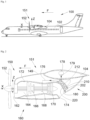
- FIG. 1 shows an aircraft 100 which has a fuselage 102 on either side of which a wing 104 is fixed. Under each wing 104 is fixed at least one propulsion unit 151.
- Fig. 2 shows the propulsion assembly 151 which includes a nacelle 149 and a propulsion system 150 surrounded by the nacelle 149.
- the propulsion system 150 takes the form of a turboprop with a propeller 152 driven in rotation by a rotating assembly mounted inside a fairing 172 of the propulsion system 150 housed inside the nacelle 149, but the propulsion system 150 can also take the form of a turbojet driving a fan.
- the propulsion system 150 comprises a rotating assembly and a movable element 152 (propeller or fan).
- X is the longitudinal axis which corresponds to the axis of rotation of the mobile element 152 oriented positively in the direction of advancement of the aircraft 100
- Y is the transverse axis which is horizontal when the aircraft is on the ground
- Z is the vertical axis or vertical height when the aircraft is on the ground, these three axes X, Y and Z being orthogonal to each other.
- the rotating assembly 160 constitutes a core of the propulsion system 150 and comprises, from front to rear, an air inlet 162 which allows the introduction of air into a vein 164 of the core, a compressor 166 which compresses the air thus introduced, a combustion chamber 168 in which the air thus compressed and a fuel mix and burn, and a turbine 170 which allows the expansion of the combustion gases and which generates the rotation which is transmitted to the mobile element, here the propeller 152.
- the elements of the rotating assembly 160 are surrounded by the fairing 172 formed of structural casings mounted around the elements of the rotating assembly 160 and allow it to be stiffened in order in particular to limit its distortions in operation.
- the fairing 172 is, on the one hand, open at the front at the air inlet 162 and delimits the vein 164 and is, on the other hand, open at the rear at the level of an ejection nozzle 174 which is downstream of the turbine 170 and therefore of the combustion chamber 168 and ensures the ejection of the combustion gases resulting from the combustion of the fuel and the air in the combustion chamber 168.
- the rear part of the fairing 172 which surrounds the ejection nozzle 174 forms the nozzle wall 180.
- the propulsion assembly 151 comprises a fuel tank 178 which is here housed in the wing 104, a supply pipe 176 which connects the tank 178 and the combustion chamber 168 and a pump 179 which sets the fuel in motion from the tank 178 to the combustion chamber 168 through the supply pipe 176.
- the fuel may be for example kerosene or dihydrogen (H 2 ).
- the fuel tank 178 may also be housed in another part of the aircraft 100, for example in the fuselage 102.
- the propulsion assembly 151 also comprises a heat exchanger system 200, 300, 400, which is arranged in the space between the nacelle 149 and the fairing 172, and which is arranged, when the propulsion system 150 is in operation, to ensure an exchange of calories between the hot combustion gases circulating in the ejection nozzle 174 and the colder fuel circulating in the supply pipe 176.
- This transfer of calories is carried out at least in part by thermal radiation through the nozzle wall 180 which is brought to a high temperature during operation of the propulsion system 150.
- the propulsion assembly 151 also comprises a cowling 210 which is fixed in a sealed manner to the nozzle wall 180 and on the outside thereof, and where the cowling 210 and the nozzle wall 180 define between them a chamber 212.
- the fixing of the cowling 210 is carried out for example by welding or riveting along the periphery of the cowling 210.
- the heat exchanger system 200, 300, 400 comprises a portion of pipe 202, 308, 402 arranged in said chamber 212 at the level of the nozzle wall 180 and the exchange of calories takes place at the level of this portion of pipe 202, 308, 402.
- the portion of pipe 202, 402 of the heat exchanger system 200, 400 is a portion of the supply pipe 176 which passes a first time through the cowling 210 to enter the chamber 212 and passes a second time through the cowling 210 to exit the chamber 212 and join the combustion chamber 168.
- the portion of pipe 202, 402 is fixed in the chamber 212 at the level of the nozzle wall 180 and the heating of the fuel takes place directly in the supply pipe 176.
- the pipe portion 202, 402 is in contact with the nozzle wall 180 or close to the latter, i.e. at a maximum distance of 50 cm.
- the portion of pipe 202 takes the form of a serpentine which runs on the outside of the nozzle wall 180.
- the pipe portion 402 of the heat exchanger system 400 surrounds the nozzle wall 180 and thus has at least one turn which surrounds the nozzle wall 180. Such an arrangement increases the transfer of calories from the combustion gases.
- the heat exchanger system 200, 400 comprises leak detection means provided at said pipe portion 202, 402 and a control unit connected to the leak detection means.
- the heat exchanger system 200, 400 also comprises a valve mounted on the supply pipe 176 downstream of the pipe portion 202, 402 relative to the fuel flow direction and controlled to open and close by the control unit.
- the control unit controls the closing of the valve when the leak detection means detect a fuel leak at the pipe portion 202, 402.
- the heat exchanger system 300 comprises a circulation pipe 304 in which a heat transfer fluid circulates, a pump 306 arranged so as to set the heat transfer fluid in motion in the circulation pipe 304, where the pipe portion 308 of the heat exchanger system 300 is a portion of the circulation pipe 304 which passes a first time through the cowling 210 to enter the chamber 212 and passes a second time through the cowling 210 to exit the chamber 212.
- the portion of pipe 308 is for example fixed in contact with the nozzle wall 180 or close to the latter, that is to say at a maximum distance of 50 cm, in order to ensure a transfer of calories from the combustion gases to the heat transfer fluid.
- the heat exchanger system 300 also includes a heat exchanger 302 arranged between the supply line 176 and the circulation line 304 so as to ensure a transfer of calories from the heat transfer fluid to the fuel.
- a heat exchanger 302 arranged between the supply line 176 and the circulation line 304 so as to ensure a transfer of calories from the heat transfer fluid to the fuel.
- the heating of the fuel is carried out indirectly by means of a heat transfer fluid.
- the portion of pipe 308 takes for example the form of a serpentine which runs on the outside of the nozzle wall 180.
- the portion of pipe 308 can also have at least one turn which surrounds the nozzle wall 180, thus taking up the variant of the Fig. 4 .
- the cowling 210 generally takes the form of a cylinder fixed around the nozzle wall 180.
- the nozzle wall 180 is pierced with a plurality of orifices 220 which open on one side into the ejection nozzle 174 and on the other side into the chamber 212.
- the diameter of the orifices 220 is between 1 mm and 3 mm. These orifices 220 then act as an acoustic attenuator at the ejection nozzle 174 by using the chamber 212 to attenuate the noise and as a passage for an air flow coming from the ejection nozzle 174 and entering the chamber 212 in order to improve the heat transfer with the pipe portion 202, 308, 402.
- the diameter of the orifices 220 is between 0.4 mm and 1 mm. These orifices 220 then act only as an acoustic attenuator at the level of the ejection nozzle 174 by using the chamber 212 to attenuate the noise.
- the nozzle wall 180 is pierced with at least one upstream orifice 310 and at least one downstream orifice 312 whose diameters are between 20 mm and 40 mm to ensure the circulation of air in the chamber 212 and improve the heat transfer with the pipe portion 308.
- the or each upstream orifice 310 is located at a front part of the cowling 210 and the or each downstream orifice 312 is located at a rear part of the cowling 210.
- the diameters of the orifices 220 are scalable along the nozzle wall 180 and adapted to the frequencies to be attenuated and vary for example between 0.4 mm and 3 mm.
- the acoustic attenuation can be improved by the installation of partitions inside the chamber 212.
- These partitions extend generally perpendicular to the nozzle wall 180 between said nozzle wall 180 and the cowling 210.
- the partitions are fixed by any suitable means such as welding or riveting.
- These partitions delimit between them cavities which open into the ejection nozzle 174 through one of the orifices 220.
- the dimensions of each cavity are adapted according to the acoustic frequencies to be attenuated.
- said portion of pipe 202, 308, 402 of the heat exchanger system 200, 300, 400 consists of a single continuous pipe.
- the portion of pipe 202, 308, 402 is welded to the cowling 210 at the level where said portion of pipe 202, 308, 402 passes through the cowling 210, that is to say to enter and exit the chamber 212. Then the cowling 210 thus equipped with the portion of pipe 202, 308, 402 is welded to the nozzle wall 180.
- the cowling 210 and the nozzle wall 180 are made of the same material.
- the cowling 210 and the pipe portion 202, 308, 402 of the heat exchanger system 200, 300, 400 are made of the same material.
- fixing means which ensure the fixing of the pipe portion 202, 308, 402 to the cowling 210.
- the fixing means are provided to allow expansion of the pipe portion.
- the fixing means are for example a plurality of collars, each being fixed to the cowling 210 and gripping the pipe portion.
- a layer of thermal insulation may be applied against the cover 210 on the side opposite said chamber 212.
Landscapes
- Engineering & Computer Science (AREA)
- Chemical & Material Sciences (AREA)
- Combustion & Propulsion (AREA)
- Mechanical Engineering (AREA)
- General Engineering & Computer Science (AREA)
- Aviation & Aerospace Engineering (AREA)
- Heat-Exchange Devices With Radiators And Conduit Assemblies (AREA)
- Fluidized-Bed Combustion And Resonant Combustion (AREA)
- Exhaust Silencers (AREA)
Claims (9)
- Antriebseinheit (151) für ein Luftfahrzeug (100), welche aufweist:- eine Gondel (149),- ein Antriebssystem (150), das im Inneren der Gondel (149) angeordnet ist und eine Verkleidung (172), eine rotierende Anordnung (160), die eine Brennkammer (168) aufweist und in der Verkleidung (172) aufgenommen ist, und eine Schubdüse (174) aufweist, die stromabwärts der Brennkammer (168) angeordnet ist und von einem hinteren Abschnitt der Verkleidung (172), Düsenwand (180) genannt, begrenzt wird und den Ausstoß der Verbrennungsgase sicherstellt, die durch die Verbrennung des Kraftstoffs in der Brennkammer (168) entstehen,- einen Kraftstofftank (178),- eine Zufuhrleitung (176), die den Tank (178) und die Brennkammer (168) verbindet,- eine Verkleidung (210), die dicht an der Düsenwand (180) und auf der Außenseite derselben befestigt ist, und wobei die Verkleidung (210) und die Düsenwand (180) zwischen sich eine Kammer (212) definieren, und- ein Wärmetauschersystem (200, 300, 400), das im Betrieb des Antriebssystems (150) einen Wärmeaustausch zwischen den heißen Verbrennungsgasen, die in der Schubdüse (174) strömen, und dem kälteren Kraftstoff, der in der Zufuhrleitung (176) strömt, wenigstens teilweise durch Wärmestrahlung durch die Düsenwand (180) hindurch sicherstellt, wobei das Wärmetauschersystem (200, 300, 400) einen Leitungsabschnitt (202, 308, 402) aufweist, der in der Kammer (212) angeordnet ist, und wobei der Wärmeaustausch an diesem Leitungsabschnitt (202, 308, 402) erfolgt,wobei die Antriebseinheit (151) dadurch gekennzeichnet ist, dass die Düsenwand (180) von mehreren Öffnungen durchbohrt ist, die auf einer Seite in die Schubdüse (174) und auf der anderen Seite in die Kammer (212) münden.
- Antriebseinheit (151) nach Anspruch 1, dadurch gekennzeichnet, dass der Leitungsabschnitt (202, 402) des Wärmetauschersystems (200) ein Abschnitt der Zufuhrleitung (176) ist.
- Antriebseinheit (151) nach Anspruch 2, dadurch gekennzeichnet, dass sie Leckdetektionsmittel, die an dem Leitungsabschnitt (202, 402) vorgesehen sind, eine Steuereinheit, die mit den Leckdetektionsmitteln verbunden ist, und ein Ventil, das an der Zufuhrleitung (176) stromabwärts des Leitungsabschnitts (202, 402) angebracht ist und durch die Steuereinheit zum Öffnen und Schließen gesteuert wird, aufweist.
- Antriebseinheit (151) nach Anspruch 1, dadurch gekennzeichnet, dass das Wärmetauschersystem (300, 400) eine Zirkulationsleitung (304), in der ein Wärmeträgerfluid zirkuliert, eine Pumpe (306), die so angeordnet ist, dass sie das Wärmeträgerfluid in der Zirkulationsleitung (304) in Bewegung versetzt, und einen Wärmetauscher (302), der zwischen der Zufuhrleitung (176) und der Zirkulationsleitung (304) angeordnet ist, aufweist, und dadurch, dass der Leitungsabschnitt (308) des Wärmetauschersystems (300, 400) ein Abschnitt (308) der Zirkulationsleitung (304) ist.
- Antriebseinheit (151) nach einem der Ansprüche 2 bis 4, dadurch gekennzeichnet, dass der Leitungsabschnitt (402) des Wärmetauschersystems (400) mindestens eine Windung aufweist, welche die Düsenwand (180) umgibt.
- Antriebseinheit (151) nach einem der Ansprüche 1 bis 5, dadurch gekennzeichnet, dass der Durchmesser der Öffnungen (220) zwischen 1 mm und 3 mm beträgt.
- Antriebseinheit (151) nach einem der Ansprüche 1 bis 5, dadurch gekennzeichnet, dass der Durchmesser der Öffnungen (220) zwischen 0,4 m und 1 mm beträgt, und dadurch, dass die Düsenwand (180) von mindestens einer stromaufwärtigen Öffnung (310) und mindestens einer stromabwärtigen Öffnung (312) durchbohrt ist, deren Durchmesser zwischen 20 mm und 40 mm betragen.
- Antriebseinheit (151) nach einem der Ansprüche 1 bis 7, dadurch gekennzeichnet, dass der Leitungsabschnitt (202, 308, 402) des Wärmetauschersystems (200, 300, 400) aus einer einzigen durchgehenden Leitung besteht.
- Luftfahrzeug (100), welches mindestens eine Antriebseinheit (151) nach einem der vorhergehenden Ansprüche aufweist.
Applications Claiming Priority (1)
| Application Number | Priority Date | Filing Date | Title |
|---|---|---|---|
| FR2110851A FR3127989A1 (fr) | 2021-10-13 | 2021-10-13 | Ensemble propulsif pour aéronef |
Publications (2)
| Publication Number | Publication Date |
|---|---|
| EP4166771A1 EP4166771A1 (de) | 2023-04-19 |
| EP4166771B1 true EP4166771B1 (de) | 2024-08-21 |
Family
ID=78649462
Family Applications (1)
| Application Number | Title | Priority Date | Filing Date |
|---|---|---|---|
| EP22200998.7A Active EP4166771B1 (de) | 2021-10-13 | 2022-10-12 | Antriebseinheit für ein flugzeug |
Country Status (4)
| Country | Link |
|---|---|
| US (1) | US11867122B2 (de) |
| EP (1) | EP4166771B1 (de) |
| CN (1) | CN115959295A (de) |
| FR (1) | FR3127989A1 (de) |
Families Citing this family (9)
| Publication number | Priority date | Publication date | Assignee | Title |
|---|---|---|---|---|
| EP4124738B1 (de) * | 2021-07-26 | 2024-08-07 | Airbus Operations (S.A.S.) | Antriebsanordnung für luftfahrzeug |
| US11952946B2 (en) * | 2021-10-15 | 2024-04-09 | Rtx Corporation | Turbine engine with preheat of cryogenic fuel via intermediate fluid |
| FR3139119A1 (fr) * | 2022-08-30 | 2024-03-01 | Airbus Operations | Ensemble propulsif pour aéronef |
| FR3146880A1 (fr) * | 2023-03-20 | 2024-09-27 | Airbus Operations (S.A.S.) | Ensemble de propulsion comprenant un système de conditionnement de carburant positionné à l’arrière d’une zone d’éjection de débris, aéronef comprenant au moins un tel ensemble de propulsion |
| US20250084792A1 (en) * | 2023-09-12 | 2025-03-13 | Pratt & Whitney Canada Corp. | Fuel containment structure for engine fuel delivery system |
| EP4538514A1 (de) * | 2023-10-12 | 2025-04-16 | Airbus (S.A.S.) | Antriebseinheit für ein flugzeug |
| EP4538515A1 (de) * | 2023-10-12 | 2025-04-16 | Airbus Operations (S.A.S.) | Antriebseinheit für ein flugzeug mit einem wärmeaustauschsystem in der abgasdüse |
| FR3154149A1 (fr) * | 2023-10-12 | 2025-04-18 | Airbus | Ensemble propulsif pour aéronef |
| FR3154766B1 (fr) * | 2023-10-30 | 2025-11-07 | Airbus Operations Sas | Ensemble propulsif pour aéronef |
Family Cites Families (19)
| Publication number | Priority date | Publication date | Assignee | Title |
|---|---|---|---|---|
| US6250061B1 (en) * | 1999-03-02 | 2001-06-26 | General Electric Company | Compressor system and methods for reducing cooling airflow |
| US7013636B2 (en) * | 2004-04-22 | 2006-03-21 | The Boeing Company | System and method for controlling the temperature and infrared signature of an engine |
| GB2476855B (en) * | 2009-11-27 | 2012-05-02 | Rolls Royce Plc | Acoustic liner and heat exchanger for gas turbine inlet duct |
| GB201208586D0 (en) * | 2012-05-16 | 2012-06-27 | Rolls Royce Plc | A heat exchanger |
| BR112015015516A2 (pt) * | 2012-12-28 | 2017-07-11 | Gen Electric | conjunto de mecanismo motor de turbina |
| US9046005B2 (en) * | 2013-04-03 | 2015-06-02 | General Electric Company | Gas turbine exhaust diffuser with helical turbulator |
| US9604438B2 (en) * | 2014-04-30 | 2017-03-28 | The Boeing Company | Methods and apparatus for noise attenuation in an engine nacelle |
| US20160017810A1 (en) * | 2014-07-21 | 2016-01-21 | United Technologies Corporation | Acoustic liner heat exchanger |
| FR3041704B1 (fr) * | 2015-09-29 | 2017-11-03 | Snecma | Panneau d'echange thermique et de reduction de bruit pour un ensemble propulsif |
| US10801408B2 (en) * | 2016-02-03 | 2020-10-13 | Rolls-Royce North American Technologies Inc. | Gas turbine engine with thermoelectric system |
| US10612468B2 (en) * | 2016-02-18 | 2020-04-07 | Rolls-Royce North American Technologies Inc. | Gas turbine engine with thermoelectric intercooler |
| US10378835B2 (en) * | 2016-03-25 | 2019-08-13 | Unison Industries, Llc | Heat exchanger with non-orthogonal perforations |
| FR3054204B1 (fr) * | 2016-07-20 | 2020-01-24 | Safran Nacelles | Nacelle de turbomoteur comportant un dispositif de refroidissement |
| US10436118B2 (en) * | 2017-06-19 | 2019-10-08 | Rohr, Inc. | Acoustic panel with folding chamber |
| US11060480B2 (en) * | 2017-11-14 | 2021-07-13 | The Boeing Company | Sound-attenuating heat exchangers and methods of utilizing the same |
| US11047307B2 (en) | 2018-09-14 | 2021-06-29 | Raytheon Technologies Corporation | Hybrid expander cycle with intercooling and turbo-generator |
| US11378341B2 (en) * | 2020-01-03 | 2022-07-05 | Raytheon Technologies Corporation | Gas turbine engine heat exchanger for annular flowpaths |
| US11629647B2 (en) * | 2020-03-27 | 2023-04-18 | Raytheon Technologies Corporation | Supercritical CO2 cycle and integrated auxiliary power for gas turbine engines |
| JP7607487B2 (ja) * | 2021-03-26 | 2024-12-27 | 北越工業株式会社 | エンジン駆動型作業機の防音箱 |
-
2021
- 2021-10-13 FR FR2110851A patent/FR3127989A1/fr not_active Withdrawn
-
2022
- 2022-10-11 US US17/963,237 patent/US11867122B2/en active Active
- 2022-10-12 CN CN202211249622.9A patent/CN115959295A/zh active Pending
- 2022-10-12 EP EP22200998.7A patent/EP4166771B1/de active Active
Also Published As
| Publication number | Publication date |
|---|---|
| EP4166771A1 (de) | 2023-04-19 |
| US11867122B2 (en) | 2024-01-09 |
| US20230167770A1 (en) | 2023-06-01 |
| CN115959295A (zh) | 2023-04-14 |
| FR3127989A1 (fr) | 2023-04-14 |
Similar Documents
| Publication | Publication Date | Title |
|---|---|---|
| EP4166771B1 (de) | Antriebseinheit für ein flugzeug | |
| EP4124738B1 (de) | Antriebsanordnung für luftfahrzeug | |
| EP1232945B1 (de) | Enteisungverfahren für die Lufteinlasshaube eines Strahltriebwerkes und Vorrichtung zur Durchführung des Verfahrens | |
| CA2371326C (fr) | Procede de degivrage par circulation forcee d'un fluide, d'un capot d'entree d'air de moteur a reaction et dispositif pour sa mise en oeuvre | |
| CA2933353C (fr) | Turbomachine d'aeronef comportant un echangeur de chaleur du type pre-refroidisseur | |
| EP1327767B1 (de) | Kühleinrichtung für eine gemeinsame Schubdüse eines Doppelstromflugtriebwerks | |
| FR3001199A1 (fr) | Capot de moteur incorporant un circuit de ventilation d'equipement | |
| WO2019081864A1 (fr) | Ensemble propulsif pour aéronef | |
| EP3487764B1 (de) | Turbinenmotorgondel mit einer kühlvorrichtung | |
| WO2009144408A2 (fr) | Chambre de combustion annulaire de moteur a turbine a gaz | |
| FR3009027A1 (fr) | Ensemble turbomachine d'aeronef a bruit de jet attenue. | |
| EP4438488B1 (de) | Flugzeugantriebsanordnung mit gondel mit t-förmigem rahmen | |
| FR3072127B1 (fr) | Conduit de decharge d'un moyeu de carter intermediaire pour turboreacteur d'aeronef comportant des canaux de refroidissement | |
| EP1577530A1 (de) | Verfahren und Vorrichtung zur Zündung eines Nachverbrenner für Zweistromtriebwerk | |
| FR3154149A1 (fr) | Ensemble propulsif pour aéronef | |
| EP4538514A1 (de) | Antriebseinheit für ein flugzeug | |
| FR3146880A1 (fr) | Ensemble de propulsion comprenant un système de conditionnement de carburant positionné à l’arrière d’une zone d’éjection de débris, aéronef comprenant au moins un tel ensemble de propulsion | |
| EP4538515A1 (de) | Antriebseinheit für ein flugzeug mit einem wärmeaustauschsystem in der abgasdüse | |
| EP3719278B1 (de) | Luftfahrzeug umfassend eine gondel | |
| EP4269768B1 (de) | Antriebseinheit für ein flugzeug | |
| FR3153077A1 (fr) | Ensemble propulsif pour aéronef | |
| EP4345009B1 (de) | Antriebseinheit für ein flugzeug | |
| FR3154766A1 (fr) | Ensemble propulsif pour aéronef | |
| EP3891372B1 (de) | Lufteinlass und verfahren zur enteisung eines lufteinlasses einer gondel eines flugzeugstrahltriebwerks | |
| WO2026021862A1 (fr) | Système de refroidissement d'une cloison interne d'une entrée d'air pour une nacelle d'aéronef et procédé associé |
Legal Events
| Date | Code | Title | Description |
|---|---|---|---|
| PUAI | Public reference made under article 153(3) epc to a published international application that has entered the european phase |
Free format text: ORIGINAL CODE: 0009012 |
|
| STAA | Information on the status of an ep patent application or granted ep patent |
Free format text: STATUS: THE APPLICATION HAS BEEN PUBLISHED |
|
| AK | Designated contracting states |
Kind code of ref document: A1 Designated state(s): AL AT BE BG CH CY CZ DE DK EE ES FI FR GB GR HR HU IE IS IT LI LT LU LV MC ME MK MT NL NO PL PT RO RS SE SI SK SM TR |
|
| STAA | Information on the status of an ep patent application or granted ep patent |
Free format text: STATUS: REQUEST FOR EXAMINATION WAS MADE |
|
| 17P | Request for examination filed |
Effective date: 20231016 |
|
| RBV | Designated contracting states (corrected) |
Designated state(s): AL AT BE BG CH CY CZ DE DK EE ES FI FR GB GR HR HU IE IS IT LI LT LU LV MC ME MK MT NL NO PL PT RO RS SE SI SK SM TR |
|
| GRAP | Despatch of communication of intention to grant a patent |
Free format text: ORIGINAL CODE: EPIDOSNIGR1 |
|
| STAA | Information on the status of an ep patent application or granted ep patent |
Free format text: STATUS: GRANT OF PATENT IS INTENDED |
|
| RIC1 | Information provided on ipc code assigned before grant |
Ipc: F02C 6/20 20060101ALI20240221BHEP Ipc: F02K 1/82 20060101ALI20240221BHEP Ipc: F02C 7/224 20060101ALI20240221BHEP Ipc: F02C 3/22 20060101AFI20240221BHEP |
|
| INTG | Intention to grant announced |
Effective date: 20240318 |
|
| GRAS | Grant fee paid |
Free format text: ORIGINAL CODE: EPIDOSNIGR3 |
|
| GRAA | (expected) grant |
Free format text: ORIGINAL CODE: 0009210 |
|
| STAA | Information on the status of an ep patent application or granted ep patent |
Free format text: STATUS: THE PATENT HAS BEEN GRANTED |
|
| AK | Designated contracting states |
Kind code of ref document: B1 Designated state(s): AL AT BE BG CH CY CZ DE DK EE ES FI FR GB GR HR HU IE IS IT LI LT LU LV MC ME MK MT NL NO PL PT RO RS SE SI SK SM TR |
|
| REG | Reference to a national code |
Ref country code: GB Ref legal event code: FG4D Free format text: NOT ENGLISH |
|
| REG | Reference to a national code |
Ref country code: CH Ref legal event code: EP |
|
| REG | Reference to a national code |
Ref country code: IE Ref legal event code: FG4D Free format text: LANGUAGE OF EP DOCUMENT: FRENCH |
|
| REG | Reference to a national code |
Ref country code: DE Ref legal event code: R096 Ref document number: 602022005467 Country of ref document: DE |
|
| REG | Reference to a national code |
Ref country code: LT Ref legal event code: MG9D |
|
| REG | Reference to a national code |
Ref country code: NL Ref legal event code: MP Effective date: 20240821 |
|
| PG25 | Lapsed in a contracting state [announced via postgrant information from national office to epo] |
Ref country code: NO Free format text: LAPSE BECAUSE OF FAILURE TO SUBMIT A TRANSLATION OF THE DESCRIPTION OR TO PAY THE FEE WITHIN THE PRESCRIBED TIME-LIMIT Effective date: 20241121 |
|
| REG | Reference to a national code |
Ref country code: AT Ref legal event code: MK05 Ref document number: 1715674 Country of ref document: AT Kind code of ref document: T Effective date: 20240821 |
|
| PG25 | Lapsed in a contracting state [announced via postgrant information from national office to epo] |
Ref country code: NL Free format text: LAPSE BECAUSE OF FAILURE TO SUBMIT A TRANSLATION OF THE DESCRIPTION OR TO PAY THE FEE WITHIN THE PRESCRIBED TIME-LIMIT Effective date: 20240821 Ref country code: PL Free format text: LAPSE BECAUSE OF FAILURE TO SUBMIT A TRANSLATION OF THE DESCRIPTION OR TO PAY THE FEE WITHIN THE PRESCRIBED TIME-LIMIT Effective date: 20240821 Ref country code: FI Free format text: LAPSE BECAUSE OF FAILURE TO SUBMIT A TRANSLATION OF THE DESCRIPTION OR TO PAY THE FEE WITHIN THE PRESCRIBED TIME-LIMIT Effective date: 20240821 Ref country code: GR Free format text: LAPSE BECAUSE OF FAILURE TO SUBMIT A TRANSLATION OF THE DESCRIPTION OR TO PAY THE FEE WITHIN THE PRESCRIBED TIME-LIMIT Effective date: 20241122 Ref country code: PT Free format text: LAPSE BECAUSE OF FAILURE TO SUBMIT A TRANSLATION OF THE DESCRIPTION OR TO PAY THE FEE WITHIN THE PRESCRIBED TIME-LIMIT Effective date: 20241223 |
|
| PG25 | Lapsed in a contracting state [announced via postgrant information from national office to epo] |
Ref country code: BG Free format text: LAPSE BECAUSE OF FAILURE TO SUBMIT A TRANSLATION OF THE DESCRIPTION OR TO PAY THE FEE WITHIN THE PRESCRIBED TIME-LIMIT Effective date: 20240821 |
|
| PG25 | Lapsed in a contracting state [announced via postgrant information from national office to epo] |
Ref country code: LV Free format text: LAPSE BECAUSE OF FAILURE TO SUBMIT A TRANSLATION OF THE DESCRIPTION OR TO PAY THE FEE WITHIN THE PRESCRIBED TIME-LIMIT Effective date: 20240821 |
|
| PG25 | Lapsed in a contracting state [announced via postgrant information from national office to epo] |
Ref country code: IS Free format text: LAPSE BECAUSE OF FAILURE TO SUBMIT A TRANSLATION OF THE DESCRIPTION OR TO PAY THE FEE WITHIN THE PRESCRIBED TIME-LIMIT Effective date: 20241221 Ref country code: AT Free format text: LAPSE BECAUSE OF FAILURE TO SUBMIT A TRANSLATION OF THE DESCRIPTION OR TO PAY THE FEE WITHIN THE PRESCRIBED TIME-LIMIT Effective date: 20240821 |
|
| PG25 | Lapsed in a contracting state [announced via postgrant information from national office to epo] |
Ref country code: HR Free format text: LAPSE BECAUSE OF FAILURE TO SUBMIT A TRANSLATION OF THE DESCRIPTION OR TO PAY THE FEE WITHIN THE PRESCRIBED TIME-LIMIT Effective date: 20240821 |
|
| PG25 | Lapsed in a contracting state [announced via postgrant information from national office to epo] |
Ref country code: RS Free format text: LAPSE BECAUSE OF FAILURE TO SUBMIT A TRANSLATION OF THE DESCRIPTION OR TO PAY THE FEE WITHIN THE PRESCRIBED TIME-LIMIT Effective date: 20241121 Ref country code: ES Free format text: LAPSE BECAUSE OF FAILURE TO SUBMIT A TRANSLATION OF THE DESCRIPTION OR TO PAY THE FEE WITHIN THE PRESCRIBED TIME-LIMIT Effective date: 20240821 |
|
| PG25 | Lapsed in a contracting state [announced via postgrant information from national office to epo] |
Ref country code: RS Free format text: LAPSE BECAUSE OF FAILURE TO SUBMIT A TRANSLATION OF THE DESCRIPTION OR TO PAY THE FEE WITHIN THE PRESCRIBED TIME-LIMIT Effective date: 20241121 Ref country code: PT Free format text: LAPSE BECAUSE OF FAILURE TO SUBMIT A TRANSLATION OF THE DESCRIPTION OR TO PAY THE FEE WITHIN THE PRESCRIBED TIME-LIMIT Effective date: 20241223 Ref country code: PL Free format text: LAPSE BECAUSE OF FAILURE TO SUBMIT A TRANSLATION OF THE DESCRIPTION OR TO PAY THE FEE WITHIN THE PRESCRIBED TIME-LIMIT Effective date: 20240821 Ref country code: NO Free format text: LAPSE BECAUSE OF FAILURE TO SUBMIT A TRANSLATION OF THE DESCRIPTION OR TO PAY THE FEE WITHIN THE PRESCRIBED TIME-LIMIT Effective date: 20241121 Ref country code: NL Free format text: LAPSE BECAUSE OF FAILURE TO SUBMIT A TRANSLATION OF THE DESCRIPTION OR TO PAY THE FEE WITHIN THE PRESCRIBED TIME-LIMIT Effective date: 20240821 Ref country code: LV Free format text: LAPSE BECAUSE OF FAILURE TO SUBMIT A TRANSLATION OF THE DESCRIPTION OR TO PAY THE FEE WITHIN THE PRESCRIBED TIME-LIMIT Effective date: 20240821 Ref country code: IS Free format text: LAPSE BECAUSE OF FAILURE TO SUBMIT A TRANSLATION OF THE DESCRIPTION OR TO PAY THE FEE WITHIN THE PRESCRIBED TIME-LIMIT Effective date: 20241221 Ref country code: HR Free format text: LAPSE BECAUSE OF FAILURE TO SUBMIT A TRANSLATION OF THE DESCRIPTION OR TO PAY THE FEE WITHIN THE PRESCRIBED TIME-LIMIT Effective date: 20240821 Ref country code: GR Free format text: LAPSE BECAUSE OF FAILURE TO SUBMIT A TRANSLATION OF THE DESCRIPTION OR TO PAY THE FEE WITHIN THE PRESCRIBED TIME-LIMIT Effective date: 20241122 Ref country code: FI Free format text: LAPSE BECAUSE OF FAILURE TO SUBMIT A TRANSLATION OF THE DESCRIPTION OR TO PAY THE FEE WITHIN THE PRESCRIBED TIME-LIMIT Effective date: 20240821 Ref country code: ES Free format text: LAPSE BECAUSE OF FAILURE TO SUBMIT A TRANSLATION OF THE DESCRIPTION OR TO PAY THE FEE WITHIN THE PRESCRIBED TIME-LIMIT Effective date: 20240821 Ref country code: BG Free format text: LAPSE BECAUSE OF FAILURE TO SUBMIT A TRANSLATION OF THE DESCRIPTION OR TO PAY THE FEE WITHIN THE PRESCRIBED TIME-LIMIT Effective date: 20240821 Ref country code: AT Free format text: LAPSE BECAUSE OF FAILURE TO SUBMIT A TRANSLATION OF THE DESCRIPTION OR TO PAY THE FEE WITHIN THE PRESCRIBED TIME-LIMIT Effective date: 20240821 |
|
| PG25 | Lapsed in a contracting state [announced via postgrant information from national office to epo] |
Ref country code: SM Free format text: LAPSE BECAUSE OF FAILURE TO SUBMIT A TRANSLATION OF THE DESCRIPTION OR TO PAY THE FEE WITHIN THE PRESCRIBED TIME-LIMIT Effective date: 20240821 Ref country code: RO Free format text: LAPSE BECAUSE OF FAILURE TO SUBMIT A TRANSLATION OF THE DESCRIPTION OR TO PAY THE FEE WITHIN THE PRESCRIBED TIME-LIMIT Effective date: 20240821 Ref country code: DK Free format text: LAPSE BECAUSE OF FAILURE TO SUBMIT A TRANSLATION OF THE DESCRIPTION OR TO PAY THE FEE WITHIN THE PRESCRIBED TIME-LIMIT Effective date: 20240821 |
|
| PG25 | Lapsed in a contracting state [announced via postgrant information from national office to epo] |
Ref country code: EE Free format text: LAPSE BECAUSE OF FAILURE TO SUBMIT A TRANSLATION OF THE DESCRIPTION OR TO PAY THE FEE WITHIN THE PRESCRIBED TIME-LIMIT Effective date: 20240821 |
|
| PG25 | Lapsed in a contracting state [announced via postgrant information from national office to epo] |
Ref country code: CZ Free format text: LAPSE BECAUSE OF FAILURE TO SUBMIT A TRANSLATION OF THE DESCRIPTION OR TO PAY THE FEE WITHIN THE PRESCRIBED TIME-LIMIT Effective date: 20240821 |
|
| PG25 | Lapsed in a contracting state [announced via postgrant information from national office to epo] |
Ref country code: IT Free format text: LAPSE BECAUSE OF FAILURE TO SUBMIT A TRANSLATION OF THE DESCRIPTION OR TO PAY THE FEE WITHIN THE PRESCRIBED TIME-LIMIT Effective date: 20240821 Ref country code: SK Free format text: LAPSE BECAUSE OF FAILURE TO SUBMIT A TRANSLATION OF THE DESCRIPTION OR TO PAY THE FEE WITHIN THE PRESCRIBED TIME-LIMIT Effective date: 20240821 |
|
| REG | Reference to a national code |
Ref country code: DE Ref legal event code: R097 Ref document number: 602022005467 Country of ref document: DE |
|
| PLBE | No opposition filed within time limit |
Free format text: ORIGINAL CODE: 0009261 |
|
| STAA | Information on the status of an ep patent application or granted ep patent |
Free format text: STATUS: NO OPPOSITION FILED WITHIN TIME LIMIT |
|
| PG25 | Lapsed in a contracting state [announced via postgrant information from national office to epo] |
Ref country code: MC Free format text: LAPSE BECAUSE OF FAILURE TO SUBMIT A TRANSLATION OF THE DESCRIPTION OR TO PAY THE FEE WITHIN THE PRESCRIBED TIME-LIMIT Effective date: 20240821 |
|
| PG25 | Lapsed in a contracting state [announced via postgrant information from national office to epo] |
Ref country code: BE Free format text: LAPSE BECAUSE OF NON-PAYMENT OF DUE FEES Effective date: 20241031 Ref country code: LU Free format text: LAPSE BECAUSE OF NON-PAYMENT OF DUE FEES Effective date: 20241012 |
|
| 26N | No opposition filed |
Effective date: 20250522 |
|
| REG | Reference to a national code |
Ref country code: BE Ref legal event code: MM Effective date: 20241031 |
|
| PG25 | Lapsed in a contracting state [announced via postgrant information from national office to epo] |
Ref country code: SE Free format text: LAPSE BECAUSE OF FAILURE TO SUBMIT A TRANSLATION OF THE DESCRIPTION OR TO PAY THE FEE WITHIN THE PRESCRIBED TIME-LIMIT Effective date: 20240821 |
|
| PG25 | Lapsed in a contracting state [announced via postgrant information from national office to epo] |
Ref country code: IE Free format text: LAPSE BECAUSE OF NON-PAYMENT OF DUE FEES Effective date: 20241012 |
|
| PGFP | Annual fee paid to national office [announced via postgrant information from national office to epo] |
Ref country code: DE Payment date: 20251021 Year of fee payment: 4 |
|
| PGFP | Annual fee paid to national office [announced via postgrant information from national office to epo] |
Ref country code: FR Payment date: 20251030 Year of fee payment: 4 |
|
| PG25 | Lapsed in a contracting state [announced via postgrant information from national office to epo] |
Ref country code: CY Free format text: LAPSE BECAUSE OF FAILURE TO SUBMIT A TRANSLATION OF THE DESCRIPTION OR TO PAY THE FEE WITHIN THE PRESCRIBED TIME-LIMIT; INVALID AB INITIO Effective date: 20221012 |
|
| PG25 | Lapsed in a contracting state [announced via postgrant information from national office to epo] |
Ref country code: HU Free format text: LAPSE BECAUSE OF FAILURE TO SUBMIT A TRANSLATION OF THE DESCRIPTION OR TO PAY THE FEE WITHIN THE PRESCRIBED TIME-LIMIT; INVALID AB INITIO Effective date: 20221012 |