EP4538514A1 - Antriebseinheit für ein flugzeug - Google Patents
Antriebseinheit für ein flugzeug Download PDFInfo
- Publication number
- EP4538514A1 EP4538514A1 EP24204611.8A EP24204611A EP4538514A1 EP 4538514 A1 EP4538514 A1 EP 4538514A1 EP 24204611 A EP24204611 A EP 24204611A EP 4538514 A1 EP4538514 A1 EP 4538514A1
- Authority
- EP
- European Patent Office
- Prior art keywords
- blade
- combustion
- propulsion
- dihydrogen
- propulsion assembly
- Prior art date
- Legal status (The legal status is an assumption and is not a legal conclusion. Google has not performed a legal analysis and makes no representation as to the accuracy of the status listed.)
- Pending
Links
- 238000002485 combustion reaction Methods 0.000 claims abstract description 38
- UFHFLCQGNIYNRP-UHFFFAOYSA-N Hydrogen Chemical compound [H][H] UFHFLCQGNIYNRP-UHFFFAOYSA-N 0.000 claims abstract description 32
- 239000000567 combustion gas Substances 0.000 claims abstract description 25
- 239000012530 fluid Substances 0.000 claims description 11
- 239000001257 hydrogen Substances 0.000 claims description 9
- 229910052739 hydrogen Inorganic materials 0.000 claims description 9
- 238000011144 upstream manufacturing Methods 0.000 claims description 5
- 238000000605 extraction Methods 0.000 claims description 3
- 238000001514 detection method Methods 0.000 description 4
- 239000000446 fuel Substances 0.000 description 4
- 210000003462 vein Anatomy 0.000 description 3
- IJGRMHOSHXDMSA-UHFFFAOYSA-N Atomic nitrogen Chemical compound N#N IJGRMHOSHXDMSA-UHFFFAOYSA-N 0.000 description 2
- 150000002431 hydrogen Chemical class 0.000 description 2
- 230000007935 neutral effect Effects 0.000 description 2
- 230000003068 static effect Effects 0.000 description 2
- 238000003466 welding Methods 0.000 description 2
- 241000861223 Issus Species 0.000 description 1
- 230000000712 assembly Effects 0.000 description 1
- 238000000429 assembly Methods 0.000 description 1
- 238000010438 heat treatment Methods 0.000 description 1
- 238000002347 injection Methods 0.000 description 1
- 239000007924 injection Substances 0.000 description 1
- 239000000463 material Substances 0.000 description 1
- 238000000034 method Methods 0.000 description 1
- 239000000203 mixture Substances 0.000 description 1
- 229910052757 nitrogen Inorganic materials 0.000 description 1
- 239000000243 solution Substances 0.000 description 1
Images

Classifications
-
- F—MECHANICAL ENGINEERING; LIGHTING; HEATING; WEAPONS; BLASTING
- F02—COMBUSTION ENGINES; HOT-GAS OR COMBUSTION-PRODUCT ENGINE PLANTS
- F02C—GAS-TURBINE PLANTS; AIR INTAKES FOR JET-PROPULSION PLANTS; CONTROLLING FUEL SUPPLY IN AIR-BREATHING JET-PROPULSION PLANTS
- F02C3/00—Gas-turbine plants characterised by the use of combustion products as the working fluid
- F02C3/20—Gas-turbine plants characterised by the use of combustion products as the working fluid using a special fuel, oxidant, or dilution fluid to generate the combustion products
- F02C3/22—Gas-turbine plants characterised by the use of combustion products as the working fluid using a special fuel, oxidant, or dilution fluid to generate the combustion products the fuel or oxidant being gaseous at standard temperature and pressure
-
- F—MECHANICAL ENGINEERING; LIGHTING; HEATING; WEAPONS; BLASTING
- F02—COMBUSTION ENGINES; HOT-GAS OR COMBUSTION-PRODUCT ENGINE PLANTS
- F02C—GAS-TURBINE PLANTS; AIR INTAKES FOR JET-PROPULSION PLANTS; CONTROLLING FUEL SUPPLY IN AIR-BREATHING JET-PROPULSION PLANTS
- F02C7/00—Features, components parts, details or accessories, not provided for in, or of interest apart form groups F02C1/00 - F02C6/00; Air intakes for jet-propulsion plants
- F02C7/22—Fuel supply systems
- F02C7/224—Heating fuel before feeding to the burner
-
- F—MECHANICAL ENGINEERING; LIGHTING; HEATING; WEAPONS; BLASTING
- F02—COMBUSTION ENGINES; HOT-GAS OR COMBUSTION-PRODUCT ENGINE PLANTS
- F02C—GAS-TURBINE PLANTS; AIR INTAKES FOR JET-PROPULSION PLANTS; CONTROLLING FUEL SUPPLY IN AIR-BREATHING JET-PROPULSION PLANTS
- F02C6/00—Plural gas-turbine plants; Combinations of gas-turbine plants with other apparatus; Adaptations of gas-turbine plants for special use
- F02C6/20—Adaptations of gas-turbine plants for driving vehicles
- F02C6/206—Adaptations of gas-turbine plants for driving vehicles the vehicles being airscrew driven
Definitions
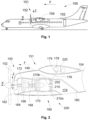
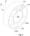
- the present invention relates to a propulsion assembly for an aircraft, said propulsion assembly comprising a propulsion system comprising an ejection nozzle ensuring the ejection of combustion gases from the propulsion system and a heat exchange system arranged at the ejection nozzle to ensure a transfer of calories to the dihydrogen of the propulsion system, as well as an aircraft comprising at least one such propulsion system.
- An object of the present invention is to propose another solution for heating dihydrogen before its combustion.
- the external volume contains a fluid.
- the propulsion assembly comprises a pump which is fluidically connected to the external volume and which is arranged to set the fluid in motion in the external volume.
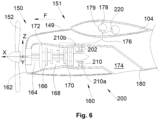
- the propulsion assembly comprises an outer ring secured to the nozzle wall, an inner ring arranged inside the outer ring and said at least one blade is fixed between the outer ring and the inner ring.
- the longitudinal axis which corresponds to the axis of rotation of the mobile element 152 oriented positively in the direction of advancement of the aircraft 100 is called X
- the transverse axis which is horizontal when the aircraft is on the ground is called Y
- the vertical axis or vertical height when the aircraft is on the ground is called Z
- a rotating assembly 160 constitutes a core of the propulsion system 150 and comprises, from front to rear, an air inlet 162 which allows the introduction of air into a vein 164 of the core, a compressor 166 which compresses the air thus introduced, a combustion chamber 168 in which the air thus compressed and dihydrogen mix and burn, and a turbine 170 which allows the expansion of the combustion gases and which generates the rotation which is transmitted to the mobile element, here the propeller 152.
- the elements of the rotating assembly 160 are surrounded by the fairing 172 formed of structural casings mounted around the elements of the rotating assembly 160 and allow it to be stiffened in order in particular to limit its distortions during operation.
- the heat exchanger system 200 thus comprises the pipe portion 202 of the supply pipe 176 and the heat exchange takes place at the level of this pipe portion 202.
- the supply pipe 176 and in particular the pipe portion 202, is a double-skinned pipe with an inner skin delimiting an inner volume in which the dihydrogen circulates and an outer skin which is around the inner skin and where an outer volume is delimited between the inner skin and the outer skin which does not contain dihydrogen under normal operating conditions, i.e. without leakage.
- the heat exchanger system 200 comprises a pump 220 which is fluidically connected to the external volume and which is arranged to set the fluid in motion in the external volume.
- the pipe portion 202 may consist of several channels, each being double-skinned, and the channels are supplied by a double collector, where a first collector supplies the different exterior volumes with fluid and where a second collector supplies the different interior volumes with dihydrogen.
- the or each blade 210 is fixed radially between the outer ring 210a and the inner ring 210b.
Landscapes
- Engineering & Computer Science (AREA)
- Chemical & Material Sciences (AREA)
- Combustion & Propulsion (AREA)
- Mechanical Engineering (AREA)
- General Engineering & Computer Science (AREA)
- Aviation & Aerospace Engineering (AREA)
- Fluidized-Bed Combustion And Resonant Combustion (AREA)
Applications Claiming Priority (1)
| Application Number | Priority Date | Filing Date | Title |
|---|---|---|---|
| FR2310977 | 2023-10-12 |
Publications (1)
| Publication Number | Publication Date |
|---|---|
| EP4538514A1 true EP4538514A1 (de) | 2025-04-16 |
Family
ID=89308430
Family Applications (1)
| Application Number | Title | Priority Date | Filing Date |
|---|---|---|---|
| EP24204611.8A Pending EP4538514A1 (de) | 2023-10-12 | 2024-10-04 | Antriebseinheit für ein flugzeug |
Country Status (1)
| Country | Link |
|---|---|
| EP (1) | EP4538514A1 (de) |
Citations (4)
| Publication number | Priority date | Publication date | Assignee | Title |
|---|---|---|---|---|
| US20130305686A1 (en) | 2010-11-23 | 2013-11-21 | Snecma | Combined turbojet and ramjet engine |
| EP4124738A1 (de) * | 2021-07-26 | 2023-02-01 | Airbus Operations (S.A.S.) | Antriebsanordnung für luftfahrzeug |
| FR3127989A1 (fr) * | 2021-10-13 | 2023-04-14 | Airbus | Ensemble propulsif pour aéronef |
| CN116591859A (zh) | 2023-04-27 | 2023-08-15 | 中国航发湖南动力机械研究所 | 一种微通道式强冷尾喷管及航空发动机 |
-
2024
- 2024-10-04 EP EP24204611.8A patent/EP4538514A1/de active Pending
Patent Citations (4)
| Publication number | Priority date | Publication date | Assignee | Title |
|---|---|---|---|---|
| US20130305686A1 (en) | 2010-11-23 | 2013-11-21 | Snecma | Combined turbojet and ramjet engine |
| EP4124738A1 (de) * | 2021-07-26 | 2023-02-01 | Airbus Operations (S.A.S.) | Antriebsanordnung für luftfahrzeug |
| FR3127989A1 (fr) * | 2021-10-13 | 2023-04-14 | Airbus | Ensemble propulsif pour aéronef |
| CN116591859A (zh) | 2023-04-27 | 2023-08-15 | 中国航发湖南动力机械研究所 | 一种微通道式强冷尾喷管及航空发动机 |
Also Published As
| Publication number | Publication date |
|---|---|
| US20250121927A1 (en) | 2025-04-17 |
Similar Documents
| Publication | Publication Date | Title |
|---|---|---|
| EP4166771B1 (de) | Antriebseinheit für ein flugzeug | |
| EP4129827B1 (de) | Luftfahrzeug mit mindestens einer vorrichtung zur wasserstoffversorgung sowie mindestens einem dichten behälter, in dem mindestens ein ausrüstungsteil der vorrichtung zur wasserstoffversorgung positioniert ist | |
| EP4124738B1 (de) | Antriebsanordnung für luftfahrzeug | |
| EP2250357B1 (de) | Luftansaugstruktur für eine flugzeugtriebwerksgondel | |
| EP3701171B1 (de) | Antriebseinheit für ein flugzeug | |
| EP2665909B1 (de) | Triebwerksgondel für nebenstrom-triebwerk | |
| EP3312391B1 (de) | Enteisungseinlass eines kompressors einer axialen turbomaschine | |
| EP4226029B1 (de) | Überschallgeschwindigkeitsdämpfer mit enteisungsvorrichtung für einen lufteinlass eines flugzeugtriebwerks und zugehöriges enteisungsverfahren | |
| BE1025263B1 (fr) | Compresseur degivrant de turbomachine et procede de degivrage | |
| EP4030043B1 (de) | Antriebseinheit für luftfahrzeug, die ein belüftungssystem und ein brandschutzsystem umfasst | |
| FR2951436A1 (fr) | Mat d'accrochage de turbomoteur d'aeronef a canalisations d'air chaud concentriques | |
| EP4538514A1 (de) | Antriebseinheit für ein flugzeug | |
| EP4438488B1 (de) | Flugzeugantriebsanordnung mit gondel mit t-förmigem rahmen | |
| EP4538513A1 (de) | Antriebseinheit für ein flugzeug | |
| EP4538515A1 (de) | Antriebseinheit für ein flugzeug mit einem wärmeaustauschsystem in der abgasdüse | |
| EP4455021A1 (de) | Flugzeug mit mindestens einer wasserstoffversorgungsvorrichtung mit mindestens einem gasabführungssystem im falle eines lecks | |
| EP3719278B1 (de) | Luftfahrzeug umfassend eine gondel | |
| EP4269768B1 (de) | Antriebseinheit für ein flugzeug | |
| EP4345009B1 (de) | Antriebseinheit für ein flugzeug | |
| EP4293212B1 (de) | Gehäusesystem mit wärmetauscher zur erwärmung von dihydrogen | |
| EP4435316B1 (de) | Modul für ein diwasserstoff-versorgungssystem für einen flugzeugmotor | |
| FR3153077A1 (fr) | Ensemble propulsif pour aéronef | |
| EP3973170B1 (de) | Verbessertes verdampfungssystem für eine trägerrakete | |
| FR3154766A1 (fr) | Ensemble propulsif pour aéronef | |
| WO2026021862A1 (fr) | Système de refroidissement d'une cloison interne d'une entrée d'air pour une nacelle d'aéronef et procédé associé |
Legal Events
| Date | Code | Title | Description |
|---|---|---|---|
| PUAI | Public reference made under article 153(3) epc to a published international application that has entered the european phase |
Free format text: ORIGINAL CODE: 0009012 |
|
| STAA | Information on the status of an ep patent application or granted ep patent |
Free format text: STATUS: REQUEST FOR EXAMINATION WAS MADE |
|
| 17P | Request for examination filed |
Effective date: 20241004 |
|
| AK | Designated contracting states |
Kind code of ref document: A1 Designated state(s): AL AT BE BG CH CY CZ DE DK EE ES FI FR GB GR HR HU IE IS IT LI LT LU LV MC ME MK MT NL NO PL PT RO RS SE SI SK SM TR |