EP4438488B1 - Flugzeugantriebsanordnung mit gondel mit t-förmigem rahmen - Google Patents
Flugzeugantriebsanordnung mit gondel mit t-förmigem rahmen Download PDFInfo
- Publication number
- EP4438488B1 EP4438488B1 EP24161503.8A EP24161503A EP4438488B1 EP 4438488 B1 EP4438488 B1 EP 4438488B1 EP 24161503 A EP24161503 A EP 24161503A EP 4438488 B1 EP4438488 B1 EP 4438488B1
- Authority
- EP
- European Patent Office
- Prior art keywords
- volume
- propulsion assembly
- sub
- wall
- dihydrogen
- Prior art date
- Legal status (The legal status is an assumption and is not a legal conclusion. Google has not performed a legal analysis and makes no representation as to the accuracy of the status listed.)
- Active
Links
Images

Classifications
-
- B—PERFORMING OPERATIONS; TRANSPORTING
- B64—AIRCRAFT; AVIATION; COSMONAUTICS
- B64D—EQUIPMENT FOR FITTING IN OR TO AIRCRAFT; FLIGHT SUITS; PARACHUTES; ARRANGEMENT OR MOUNTING OF POWER PLANTS OR PROPULSION TRANSMISSIONS IN AIRCRAFT
- B64D37/00—Arrangements in connection with fuel supply for power plant
- B64D37/30—Fuel systems for specific fuels
-
- B—PERFORMING OPERATIONS; TRANSPORTING
- B64—AIRCRAFT; AVIATION; COSMONAUTICS
- B64D—EQUIPMENT FOR FITTING IN OR TO AIRCRAFT; FLIGHT SUITS; PARACHUTES; ARRANGEMENT OR MOUNTING OF POWER PLANTS OR PROPULSION TRANSMISSIONS IN AIRCRAFT
- B64D27/00—Arrangement or mounting of power plants in aircraft; Aircraft characterised by the type or position of power plants
- B64D27/02—Aircraft characterised by the type or position of power plants
- B64D27/16—Aircraft characterised by the type or position of power plants of jet type
- B64D27/18—Aircraft characterised by the type or position of power plants of jet type within, or attached to, wings
-
- B—PERFORMING OPERATIONS; TRANSPORTING
- B64—AIRCRAFT; AVIATION; COSMONAUTICS
- B64D—EQUIPMENT FOR FITTING IN OR TO AIRCRAFT; FLIGHT SUITS; PARACHUTES; ARRANGEMENT OR MOUNTING OF POWER PLANTS OR PROPULSION TRANSMISSIONS IN AIRCRAFT
- B64D27/00—Arrangement or mounting of power plants in aircraft; Aircraft characterised by the type or position of power plants
- B64D27/40—Arrangements for mounting power plants in aircraft
-
- B—PERFORMING OPERATIONS; TRANSPORTING
- B64—AIRCRAFT; AVIATION; COSMONAUTICS
- B64D—EQUIPMENT FOR FITTING IN OR TO AIRCRAFT; FLIGHT SUITS; PARACHUTES; ARRANGEMENT OR MOUNTING OF POWER PLANTS OR PROPULSION TRANSMISSIONS IN AIRCRAFT
- B64D27/00—Arrangement or mounting of power plants in aircraft; Aircraft characterised by the type or position of power plants
- B64D27/40—Arrangements for mounting power plants in aircraft
- B64D27/404—Suspension arrangements specially adapted for supporting vertical loads
-
- B—PERFORMING OPERATIONS; TRANSPORTING
- B64—AIRCRAFT; AVIATION; COSMONAUTICS
- B64D—EQUIPMENT FOR FITTING IN OR TO AIRCRAFT; FLIGHT SUITS; PARACHUTES; ARRANGEMENT OR MOUNTING OF POWER PLANTS OR PROPULSION TRANSMISSIONS IN AIRCRAFT
- B64D29/00—Power-plant nacelles, fairings or cowlings
- B64D29/02—Power-plant nacelles, fairings or cowlings associated with wings
-
- B—PERFORMING OPERATIONS; TRANSPORTING
- B64—AIRCRAFT; AVIATION; COSMONAUTICS
- B64D—EQUIPMENT FOR FITTING IN OR TO AIRCRAFT; FLIGHT SUITS; PARACHUTES; ARRANGEMENT OR MOUNTING OF POWER PLANTS OR PROPULSION TRANSMISSIONS IN AIRCRAFT
- B64D37/00—Arrangements in connection with fuel supply for power plant
- B64D37/02—Tanks
- B64D37/14—Filling or emptying
- B64D37/20—Emptying systems
-
- B—PERFORMING OPERATIONS; TRANSPORTING
- B64—AIRCRAFT; AVIATION; COSMONAUTICS
- B64D—EQUIPMENT FOR FITTING IN OR TO AIRCRAFT; FLIGHT SUITS; PARACHUTES; ARRANGEMENT OR MOUNTING OF POWER PLANTS OR PROPULSION TRANSMISSIONS IN AIRCRAFT
- B64D37/00—Arrangements in connection with fuel supply for power plant
- B64D37/32—Safety measures not otherwise provided for, e.g. preventing explosive conditions
-
- B—PERFORMING OPERATIONS; TRANSPORTING
- B64—AIRCRAFT; AVIATION; COSMONAUTICS
- B64D—EQUIPMENT FOR FITTING IN OR TO AIRCRAFT; FLIGHT SUITS; PARACHUTES; ARRANGEMENT OR MOUNTING OF POWER PLANTS OR PROPULSION TRANSMISSIONS IN AIRCRAFT
- B64D45/00—Aircraft indicators or protectors not otherwise provided for
-
- F—MECHANICAL ENGINEERING; LIGHTING; HEATING; WEAPONS; BLASTING
- F02—COMBUSTION ENGINES; HOT-GAS OR COMBUSTION-PRODUCT ENGINE PLANTS
- F02K—JET-PROPULSION PLANTS
- F02K1/00—Plants characterised by the form or arrangement of the jet pipe or nozzle; Jet pipes or nozzles peculiar thereto
- F02K1/36—Plants characterised by the form or arrangement of the jet pipe or nozzle; Jet pipes or nozzles peculiar thereto having an ejector
-
- B—PERFORMING OPERATIONS; TRANSPORTING
- B64—AIRCRAFT; AVIATION; COSMONAUTICS
- B64D—EQUIPMENT FOR FITTING IN OR TO AIRCRAFT; FLIGHT SUITS; PARACHUTES; ARRANGEMENT OR MOUNTING OF POWER PLANTS OR PROPULSION TRANSMISSIONS IN AIRCRAFT
- B64D27/00—Arrangement or mounting of power plants in aircraft; Aircraft characterised by the type or position of power plants
- B64D27/02—Aircraft characterised by the type or position of power plants
- B64D27/10—Aircraft characterised by the type or position of power plants of gas-turbine type
- B64D27/12—Aircraft characterised by the type or position of power plants of gas-turbine type within, or attached to, wings
-
- F—MECHANICAL ENGINEERING; LIGHTING; HEATING; WEAPONS; BLASTING
- F02—COMBUSTION ENGINES; HOT-GAS OR COMBUSTION-PRODUCT ENGINE PLANTS
- F02M—SUPPLYING COMBUSTION ENGINES IN GENERAL WITH COMBUSTIBLE MIXTURES OR CONSTITUENTS THEREOF
- F02M21/00—Apparatus for supplying engines with non-liquid fuels, e.g. gaseous fuels stored in liquid form
- F02M21/02—Apparatus for supplying engines with non-liquid fuels, e.g. gaseous fuels stored in liquid form for gaseous fuels
- F02M21/0203—Apparatus for supplying engines with non-liquid fuels, e.g. gaseous fuels stored in liquid form for gaseous fuels characterised by the type of gaseous fuel
- F02M21/0206—Non-hydrocarbon fuels, e.g. hydrogen, ammonia or carbon monoxide
Definitions
- the present invention relates to a propulsion assembly for an aircraft, where the propulsion assembly comprises a nacelle in which an engine is housed and which is equipped with a T-frame which divides the interior volume of the nacelle into two sub-volumes, as well as to an aircraft comprising at least one such propulsion assembly.
- An aircraft typically has at least one engine, particularly a turbojet.
- the engine is enclosed in a nacelle which consists of cowls that are attached to a structure internal to the nacelle.
- the engine is supplied with fuel from a tank located inside the aircraft.
- the fuel supply is carried out through pipes that run between the tank and the engine, passing through, among other places, the interior of the nacelle.
- An object of the present invention is to propose a propulsion assembly comprising a nacelle which comprises means for ensuring a continuous supply of the engine even in the event of damage to part of the hydrogen distribution system.
- each treatment system is fixed to the chassis.
- each treatment system comprises a pump having an inlet fluidically connected to the corresponding supply pipe, a heat exchanger having an outlet fluidically connected to the corresponding supply pipe, and an intermediate pipe fluidically connected between an outlet of the pump and an inlet of the heat exchanger.
- a motor housed in the nacelle has an ejection nozzle, and the chassis has a sheath secured to the second wall where the sheath is fitted onto the ejection nozzle.
- the invention also proposes an aircraft comprising a wing, a dihydrogen tank and a propulsion unit according to one of the preceding variants, where the first wall is fixed against the lower surface of the wing and where each supply pipe is fluidically connected to the dihydrogen tank.
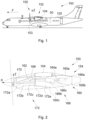
- FIG. 1 shows an aircraft 100 which has a fuselage 102 to which is fixed on either side a wing 104 and a tank 50 containing dihydrogen.
- the aircraft 100 also comprises at least one propulsion unit 150 which is fixed under the wing 104 and which comprises a nacelle 152 and an engine, in particular a turbojet, and which is enclosed in the nacelle 152.
- X is the longitudinal direction of the propulsion unit 150 which is generally horizontal and oriented positively in the direction of advance F of the aircraft 100
- Y is the transverse direction of the propulsion unit 150 which is horizontal when the aircraft 100 is on the ground
- Z is the vertical direction or vertical height when the aircraft 100 is on the ground, these three directions X, Y and Z being orthogonal to each other.
- forward and rear are to be considered in relation to the direction of advance F of the aircraft 100 under the effect of the thrust provided by the operating engine.
- the propulsion unit 150 has a vertical median plane XZ.
- the engine is equipped with a propeller which is rotatable about an axis parallel to the longitudinal direction X, but, instead, it can be equipped with a fan.
- FIG. 2 shows the propulsion unit 150 without the nacelle 152.
- the nacelle 152 comprises several covers 153 which are fixed to an internal structure of the nacelle 152 and which comprises for example a front primary structure 170 which here consists of bars fixed together and which are fixed to a structure of the wing 104.
- the engine 172 conventionally comprises, from upstream to downstream relative to the direction of air flow in the engine 172, an air inlet 172a, a compressor 172b, a combustion chamber 172c, an expander 172d and an ejection nozzle 172e.
- the covers 153 delimit an interior volume 154 in which the engine 172 and the internal structure are housed, leaving open passages for the air inlet 172a and the ejection nozzle 172e.
- FIG. 3 shows a portion of the propulsion assembly 150 without the nacelle 152.
- the propulsion unit 150 comprises a chassis 160 which is housed in the interior volume 154 and which takes the form of a T-shaped profile with a first wall 160a and a second wall 160b secured to the first wall 160a.
- the T-profile extends parallel to the longitudinal direction X.
- the first wall 160a extends generally horizontally and is fixed against the intrados of the wing 104.
- the second wall 160b extends generally vertically under the first wall 160a and substantially in the middle of the first wall 160a to divide the interior volume 154 into two sub-volumes 154a-b, namely a sub-volume 154a to the port side of the second wall 160b and a sub-volume 154b to the starboard side of the second wall 160b.
- the second wall 160b is generally aligned with the median plane XZ.
- the propulsion assembly 150 also comprises a consumer device 162 which, in the embodiment of the invention presented in Figure 2 , is constituted by the combustion chamber 172c, but which could take another form such as a fuel cell.
- the consumer device 162 consumes the dihydrogen from the tank 50.
- the consumer device 162 is housed in the interior volume 154.
- the propulsion unit 150 comprises a treatment system 166 which treats the dihydrogen.
- a treatment system 166 is provided for each sub-volume 154a-b, housed in said sub-volume 154a-b, i.e. there is a treatment system 166 on either side of the second wall 160b.
- the propulsion assembly 150 For each treatment system 166, the propulsion assembly 150 comprises a supply pipe 168 housed in the sub-volume 154a-b corresponding to said treatment system 166 and fluidically connected between the treatment system 166 and the consumer device 162.
- the propulsion assembly 150 For each sub-volume 154a-b, the propulsion assembly 150 comprises a supply pipe 164a-b fluidically connected to the treatment system 166 corresponding to said sub-volume 154a-b and which is fluidically connected to the hydrogen tank 50.
- Each supply pipe 164a-b extends partly into the associated sub-volume 154a-b and partly outside the associated sub-volume 154a-b by crossing the first wall 160a to reach the tank 50.
- the 160 frame is made of a fire and high temperature resistant material, such as metal.
- fire resistance is achieved by installing a thermal mattress and a protective sheet which are fixed to the frame 160. Fire resistance is then achieved by the parts thus added.
- the T-shape of the chassis 160 thus provides protection transversely between the two sub-volumes 154a-b and vertically between the propulsion unit 150 and the wing 104.
- each processing system 166 is fixed to the chassis 160 by any suitable fixing means such as bolts.
- each treatment system 166 comprises a pump 166a having an inlet fluidically connected to the corresponding supply pipe 164a-b, a heat exchanger 166b having an outlet fluidically connected to the corresponding supply pipe 168, and an intermediate pipe 166c which is fluidically connected between an outlet of the pump 166a and an inlet of the heat exchanger 166b.
- Such an arrangement makes it possible to take liquid hydrogen from the tank 50 and propel it towards the consumer device 162 by transforming it into gaseous hydrogen for better efficiency in said consumer device 162.
- the heat exchanger 166b is further supplied with another fluid constituting a heat source relative to the dihydrogen.
- Said other fluid is for example nitrogen circulating in a closed loop and heated by the engine 172.
- the pump 166a and the heat exchanger 166b are fixed to the second wall 160b.
- the frame 160 is not fixed directly to the internal structure of the nacelle 152, but it is fixed to the structure of the wing 104 shown in the Figure 3 by a transverse beam 302 which is itself crossed by the supply pipes 164a-b.
- the fixing is ensured by any suitable means such as bolts.
- the chassis 160 has a sheath 160c which is integral with the second wall 160b and which is arranged here at the base of said second wall 160b.
- the sheath 160c is fitted onto the ejection nozzle 172e which ensures that the chassis 160 is held in place.
- the sheath 160c is thus open at its two ends to allow the passage of the ejection nozzle 172e and the evacuation of the combustion gases to the outside.
- the shape of the sheath 160c is thus adapted to the shape of the ejection nozzle 172.
Landscapes
- Engineering & Computer Science (AREA)
- Aviation & Aerospace Engineering (AREA)
- Chemical & Material Sciences (AREA)
- Combustion & Propulsion (AREA)
- Mechanical Engineering (AREA)
- General Engineering & Computer Science (AREA)
- Structures Of Non-Positive Displacement Pumps (AREA)
- Filling Or Discharging Of Gas Storage Vessels (AREA)
Claims (5)
- Antriebsanordnung (150) für ein Flugzeug (100), das einen Flügel (104) und einen Wasserstofftank (50) umfasst, wobei die Antriebsanordnung (150) Folgendes umfasst:- eine Gondel (152), die Hauben (153) beinhaltet, die einen Innenraum (154) begrenzen,- einen Rahmen (160), der in dem Innenraum (154) aufgenommen ist,- eine Verbrauchervorrichtung (162), die in dem Innenraum (154) aufgenommen ist und dazu vorgesehen ist, Wasserstoff zu verbrauchen,dadurch gekennzeichnet, dass:- der Rahmen (160) im Querschnitt T-förmig ausgebildet ist und eine erste Wand (160a), die dazu bestimmt ist, an der Druckseite des Flügels (104) befestigt zu sein, und eine zweite Wand (160b), die sich vertikal unter der ersten Wand (160a) erstreckt und dabei den Innenraum (154) in zwei Teilräume (154a-b) unterteilt, wenn die Antriebsanordnung (150) an dem Flugzeug montiert ist, umfasst,und dass die Antriebsanordnung (150) ferner Folgendes umfasst:- für jeden Teilraum (154a-b), ein Aufbereitungssystem (166), das in dem Teilraum (154a-b) aufgenommen ist und dazu bestimmt ist, Wasserstoff aufzubereiten,- für jedes Aufbereitungssystem (166), eine Versorgungsleitung (168), die in dem assoziierten Teilraum (154a-b) aufgenommen ist und fluidisch zwischen dem Aufbereitungssystem (166) und der Verbrauchervorrichtung (162) verbunden ist, und- für jeden Teilraum (154a-b), eine Zuführungsleitung (164a-b), die mit dem assoziierten Aufbereitungssystem (166) fluidisch verbunden ist und dazu bestimmt ist, fluidisch mit dem Wasserstofftank (50) verbunden zu sein, wobei sich die Zuführungsleitung (164a-b) teilweise in dem assoziierten Teilraum (154a-b) und teilweise außerhalb des assoziierten Teilraums (154a-b) erstreckt und dabei die erste Wand (160a) durchquert.
- Antriebsanordnung (150) nach Anspruch 1, dadurch gekennzeichnet, dass jedes Aufbereitungssystem (166) an dem Rahmen (160) befestigt ist.
- Antriebsanordnung (150) nach einem der Ansprüche 1 oder 2, dadurch gekennzeichnet, dass jedes Aufbereitungssystem (166) eine Pumpe (166a), von der ein Einlass fluidisch mit der entsprechenden Zuführungsleitung (164a-b) verbunden ist, einen Wärmetauscher (166b), von dem ein Auslass fluidisch mit der entsprechenden Versorgungsleitung (168) verbunden ist, und eine Zwischenleitung (166c), die fluidisch zwischen einem Auslass der Pumpe (166a) und einem Einlass des Wärmetauschers (166b) verbunden ist, umfasst.
- Antriebsanordnung (150) nach einem der Ansprüche 1 bis 3, dadurch gekennzeichnet, dass ein Motor (172), der in der Gondel (152) aufgenommen ist, eine Ausstoßdüse (172e) umfasst und dass der Rahmen (160) eine Hülse (160c) aufweist, die mit der zweiten Wand (160b) fest verbunden ist, wobei die Hülse (160c) auf die Ausstoßdüse (172e) aufgeschoben ist.
- Flugzeug (100), das einen Flügel (104), einen Wasserstofftank (50) und eine Antriebsanordnung (150) nach einem der vorhergehenden Ansprüche umfasst, wobei die erste Wand (160a) an der Druckseite des Flügels (104) befestigt ist und wobei jede Zuführungsleitung (164a-b) fluidisch mit dem Wasserstofftank (50) verbunden ist.
Applications Claiming Priority (1)
| Application Number | Priority Date | Filing Date | Title |
|---|---|---|---|
| FR2302991A FR3147252A1 (fr) | 2023-03-29 | 2023-03-29 | Ensemble propulsif d’aéronef comportant une nacelle avec un châssis en t |
Publications (2)
| Publication Number | Publication Date |
|---|---|
| EP4438488A1 EP4438488A1 (de) | 2024-10-02 |
| EP4438488B1 true EP4438488B1 (de) | 2025-05-14 |
Family
ID=86851617
Family Applications (1)
| Application Number | Title | Priority Date | Filing Date |
|---|---|---|---|
| EP24161503.8A Active EP4438488B1 (de) | 2023-03-29 | 2024-03-05 | Flugzeugantriebsanordnung mit gondel mit t-förmigem rahmen |
Country Status (3)
| Country | Link |
|---|---|
| US (1) | US12296975B2 (de) |
| EP (1) | EP4438488B1 (de) |
| FR (1) | FR3147252A1 (de) |
Families Citing this family (1)
| Publication number | Priority date | Publication date | Assignee | Title |
|---|---|---|---|---|
| US12377995B2 (en) * | 2022-11-22 | 2025-08-05 | Embraer S.A. | Aircraft tail mounted fuel cell power train and thermal management systems |
Family Cites Families (10)
| Publication number | Priority date | Publication date | Assignee | Title |
|---|---|---|---|---|
| US4437627A (en) * | 1982-03-12 | 1984-03-20 | The Boeing Company | Integrated power plant installation system |
| DE3374546D1 (en) * | 1983-12-19 | 1987-12-23 | Boeing Co | Apparatus and method for minimizing engine backbone bending |
| US5467941A (en) * | 1993-12-30 | 1995-11-21 | The Boeing Company | Pylon and engine installation for ultra-high by-pass turbo-fan engines |
| US6802479B2 (en) * | 2002-05-16 | 2004-10-12 | The Boeing Company | Flammable fluid line shroud |
| EP2076438A2 (de) | 2006-10-11 | 2009-07-08 | Aircelle | Bypassgasturbinengondel |
| US9027875B2 (en) * | 2010-10-28 | 2015-05-12 | Spirit Aerosystems, Inc. | Pylon arrangement for open structure |
| GB201311072D0 (en) | 2013-06-21 | 2013-08-07 | Rolls Royce Deutschland & Co Kg | An accessory mounting for a gas turbine engine |
| EP3071481B1 (de) * | 2013-11-18 | 2020-01-08 | LORD Corporation | Befestigungssysteme und verfahren für turboprop-triebwerk |
| FR3120603A1 (fr) * | 2021-03-11 | 2022-09-16 | Airbus Operations (S.A.S.) | Mât d’aéronef comprenant une structure primaire tubulaire intégrant au moins une canalisation à double peau et aéronef comportant au moins un tel mât |
| US11988158B2 (en) * | 2021-07-19 | 2024-05-21 | Pratt & Whitney Canada Corp. | Multi-fuel engine for an aircraft |
-
2023
- 2023-03-29 FR FR2302991A patent/FR3147252A1/fr not_active Ceased
-
2024
- 2024-03-05 EP EP24161503.8A patent/EP4438488B1/de active Active
- 2024-03-12 US US18/602,498 patent/US12296975B2/en active Active
Also Published As
| Publication number | Publication date |
|---|---|
| US20240327023A1 (en) | 2024-10-03 |
| FR3147252A1 (fr) | 2024-10-04 |
| EP4438488A1 (de) | 2024-10-02 |
| US12296975B2 (en) | 2025-05-13 |
Similar Documents
| Publication | Publication Date | Title |
|---|---|---|
| EP4129827B1 (de) | Luftfahrzeug mit mindestens einer vorrichtung zur wasserstoffversorgung sowie mindestens einem dichten behälter, in dem mindestens ein ausrüstungsteil der vorrichtung zur wasserstoffversorgung positioniert ist | |
| EP4166771B1 (de) | Antriebseinheit für ein flugzeug | |
| EP4124738B1 (de) | Antriebsanordnung für luftfahrzeug | |
| EP2219948B1 (de) | Luftauslasssystem für die eintrittskante eines flugzeuges | |
| EP2032822B1 (de) | Gasturbinentriebwerk für ein luftfahrzeug | |
| EP4438488B1 (de) | Flugzeugantriebsanordnung mit gondel mit t-förmigem rahmen | |
| EP1907281A1 (de) | Antriebseinheit für flugzeug und mindestens eine solche antriebsvorrichtung umfassendes flugzeug | |
| WO2014202881A1 (fr) | Ventilation d'une nacelle de turbomachine | |
| WO2013102739A1 (fr) | Joint d ' étancheité pour pylone et nacelle de turboréacteur et ensemble de pylone et nacelle de turboréacteur incorporant un tel joint d ' étancheité | |
| FR3072908A1 (fr) | Ensemble propulsif pour aeronef | |
| FR3072421B1 (fr) | Levre d'entree d'air d'un moteur d'aeronef comportant un systeme de degivrage | |
| WO2013060985A1 (fr) | Module de chambre de combustion de turbomachine d'aéronef et procédé de conception de celui-ci | |
| FR2951436A1 (fr) | Mat d'accrochage de turbomoteur d'aeronef a canalisations d'air chaud concentriques | |
| FR3120352A1 (fr) | Entree d’air de nacelle munie d’un système de protection contre la glace mixte | |
| FR3146880A1 (fr) | Ensemble de propulsion comprenant un système de conditionnement de carburant positionné à l’arrière d’une zone d’éjection de débris, aéronef comprenant au moins un tel ensemble de propulsion | |
| EP4331993A1 (de) | Antriebseinheit für ein flugzeug | |
| EP4345009B1 (de) | Antriebseinheit für ein flugzeug | |
| EP4538513A1 (de) | Antriebseinheit für ein flugzeug | |
| EP4538514A1 (de) | Antriebseinheit für ein flugzeug | |
| EP4293212B1 (de) | Gehäusesystem mit wärmetauscher zur erwärmung von dihydrogen | |
| EP4538515A1 (de) | Antriebseinheit für ein flugzeug mit einem wärmeaustauschsystem in der abgasdüse | |
| FR3151299A1 (fr) | Ensemble propulsif pour aéronef | |
| EP4435316B1 (de) | Modul für ein diwasserstoff-versorgungssystem für einen flugzeugmotor | |
| EP4458682B1 (de) | Flugzeug mit mindestens einer flüssigkeitsversorgungsschaltung mit mindestens einem selbstschliessenden verschluss | |
| EP4452757A1 (de) | Integration eines feuerlöschers in eine feuer-zone einer turbomaschine |
Legal Events
| Date | Code | Title | Description |
|---|---|---|---|
| PUAI | Public reference made under article 153(3) epc to a published international application that has entered the european phase |
Free format text: ORIGINAL CODE: 0009012 |
|
| STAA | Information on the status of an ep patent application or granted ep patent |
Free format text: STATUS: REQUEST FOR EXAMINATION WAS MADE |
|
| 17P | Request for examination filed |
Effective date: 20240305 |
|
| AK | Designated contracting states |
Kind code of ref document: A1 Designated state(s): AL AT BE BG CH CY CZ DE DK EE ES FI FR GB GR HR HU IE IS IT LI LT LU LV MC ME MK MT NL NO PL PT RO RS SE SI SK SM TR |
|
| GRAP | Despatch of communication of intention to grant a patent |
Free format text: ORIGINAL CODE: EPIDOSNIGR1 |
|
| STAA | Information on the status of an ep patent application or granted ep patent |
Free format text: STATUS: GRANT OF PATENT IS INTENDED |
|
| RIC1 | Information provided on ipc code assigned before grant |
Ipc: B64D 27/12 20060101ALN20241104BHEP Ipc: F02M 21/02 20060101ALI20241104BHEP Ipc: B64D 45/00 20060101ALI20241104BHEP Ipc: B64D 27/40 20240101ALI20241104BHEP Ipc: B64D 37/20 20060101ALI20241104BHEP Ipc: B64D 37/32 20060101ALI20241104BHEP Ipc: B64D 37/30 20060101ALI20241104BHEP Ipc: B64D 29/02 20060101AFI20241104BHEP |
|
| INTG | Intention to grant announced |
Effective date: 20241121 |
|
| GRAS | Grant fee paid |
Free format text: ORIGINAL CODE: EPIDOSNIGR3 |
|
| GRAA | (expected) grant |
Free format text: ORIGINAL CODE: 0009210 |
|
| STAA | Information on the status of an ep patent application or granted ep patent |
Free format text: STATUS: THE PATENT HAS BEEN GRANTED |
|
| AK | Designated contracting states |
Kind code of ref document: B1 Designated state(s): AL AT BE BG CH CY CZ DE DK EE ES FI FR GB GR HR HU IE IS IT LI LT LU LV MC ME MK MT NL NO PL PT RO RS SE SI SK SM TR |
|
| REG | Reference to a national code |
Ref country code: GB Ref legal event code: FG4D Free format text: NOT ENGLISH |
|
| REG | Reference to a national code |
Ref country code: CH Ref legal event code: EP |
|
| REG | Reference to a national code |
Ref country code: IE Ref legal event code: FG4D Free format text: LANGUAGE OF EP DOCUMENT: FRENCH |
|
| REG | Reference to a national code |
Ref country code: DE Ref legal event code: R096 Ref document number: 602024000125 Country of ref document: DE |
|
| REG | Reference to a national code |
Ref country code: NL Ref legal event code: MP Effective date: 20250514 |
|
| PG25 | Lapsed in a contracting state [announced via postgrant information from national office to epo] |
Ref country code: PT Free format text: LAPSE BECAUSE OF FAILURE TO SUBMIT A TRANSLATION OF THE DESCRIPTION OR TO PAY THE FEE WITHIN THE PRESCRIBED TIME-LIMIT Effective date: 20250915 Ref country code: FI Free format text: LAPSE BECAUSE OF FAILURE TO SUBMIT A TRANSLATION OF THE DESCRIPTION OR TO PAY THE FEE WITHIN THE PRESCRIBED TIME-LIMIT Effective date: 20250514 Ref country code: ES Free format text: LAPSE BECAUSE OF FAILURE TO SUBMIT A TRANSLATION OF THE DESCRIPTION OR TO PAY THE FEE WITHIN THE PRESCRIBED TIME-LIMIT Effective date: 20250514 |
|
| REG | Reference to a national code |
Ref country code: LT Ref legal event code: MG9D |
|
| PG25 | Lapsed in a contracting state [announced via postgrant information from national office to epo] |
Ref country code: NO Free format text: LAPSE BECAUSE OF FAILURE TO SUBMIT A TRANSLATION OF THE DESCRIPTION OR TO PAY THE FEE WITHIN THE PRESCRIBED TIME-LIMIT Effective date: 20250814 Ref country code: GR Free format text: LAPSE BECAUSE OF FAILURE TO SUBMIT A TRANSLATION OF THE DESCRIPTION OR TO PAY THE FEE WITHIN THE PRESCRIBED TIME-LIMIT Effective date: 20250815 |
|
| PG25 | Lapsed in a contracting state [announced via postgrant information from national office to epo] |
Ref country code: NL Free format text: LAPSE BECAUSE OF FAILURE TO SUBMIT A TRANSLATION OF THE DESCRIPTION OR TO PAY THE FEE WITHIN THE PRESCRIBED TIME-LIMIT Effective date: 20250514 Ref country code: PL Free format text: LAPSE BECAUSE OF FAILURE TO SUBMIT A TRANSLATION OF THE DESCRIPTION OR TO PAY THE FEE WITHIN THE PRESCRIBED TIME-LIMIT Effective date: 20250514 |
|
| REG | Reference to a national code |
Ref country code: AT Ref legal event code: MK05 Ref document number: 1794619 Country of ref document: AT Kind code of ref document: T Effective date: 20250514 |
|
| PG25 | Lapsed in a contracting state [announced via postgrant information from national office to epo] |
Ref country code: BG Free format text: LAPSE BECAUSE OF FAILURE TO SUBMIT A TRANSLATION OF THE DESCRIPTION OR TO PAY THE FEE WITHIN THE PRESCRIBED TIME-LIMIT Effective date: 20250514 |
|
| PG25 | Lapsed in a contracting state [announced via postgrant information from national office to epo] |
Ref country code: HR Free format text: LAPSE BECAUSE OF FAILURE TO SUBMIT A TRANSLATION OF THE DESCRIPTION OR TO PAY THE FEE WITHIN THE PRESCRIBED TIME-LIMIT Effective date: 20250514 |
|
| PG25 | Lapsed in a contracting state [announced via postgrant information from national office to epo] |
Ref country code: AT Free format text: LAPSE BECAUSE OF FAILURE TO SUBMIT A TRANSLATION OF THE DESCRIPTION OR TO PAY THE FEE WITHIN THE PRESCRIBED TIME-LIMIT Effective date: 20250514 |
|
| PG25 | Lapsed in a contracting state [announced via postgrant information from national office to epo] |
Ref country code: RS Free format text: LAPSE BECAUSE OF FAILURE TO SUBMIT A TRANSLATION OF THE DESCRIPTION OR TO PAY THE FEE WITHIN THE PRESCRIBED TIME-LIMIT Effective date: 20250814 |
|
| PG25 | Lapsed in a contracting state [announced via postgrant information from national office to epo] |
Ref country code: IS Free format text: LAPSE BECAUSE OF FAILURE TO SUBMIT A TRANSLATION OF THE DESCRIPTION OR TO PAY THE FEE WITHIN THE PRESCRIBED TIME-LIMIT Effective date: 20250914 |
|
| PG25 | Lapsed in a contracting state [announced via postgrant information from national office to epo] |
Ref country code: LV Free format text: LAPSE BECAUSE OF FAILURE TO SUBMIT A TRANSLATION OF THE DESCRIPTION OR TO PAY THE FEE WITHIN THE PRESCRIBED TIME-LIMIT Effective date: 20250514 |
|
| PG25 | Lapsed in a contracting state [announced via postgrant information from national office to epo] |
Ref country code: SM Free format text: LAPSE BECAUSE OF FAILURE TO SUBMIT A TRANSLATION OF THE DESCRIPTION OR TO PAY THE FEE WITHIN THE PRESCRIBED TIME-LIMIT Effective date: 20250514 Ref country code: DK Free format text: LAPSE BECAUSE OF FAILURE TO SUBMIT A TRANSLATION OF THE DESCRIPTION OR TO PAY THE FEE WITHIN THE PRESCRIBED TIME-LIMIT Effective date: 20250514 |
|
| PG25 | Lapsed in a contracting state [announced via postgrant information from national office to epo] |
Ref country code: CZ Free format text: LAPSE BECAUSE OF FAILURE TO SUBMIT A TRANSLATION OF THE DESCRIPTION OR TO PAY THE FEE WITHIN THE PRESCRIBED TIME-LIMIT Effective date: 20250514 |
|
| PG25 | Lapsed in a contracting state [announced via postgrant information from national office to epo] |
Ref country code: EE Free format text: LAPSE BECAUSE OF FAILURE TO SUBMIT A TRANSLATION OF THE DESCRIPTION OR TO PAY THE FEE WITHIN THE PRESCRIBED TIME-LIMIT Effective date: 20250514 |
|
| PG25 | Lapsed in a contracting state [announced via postgrant information from national office to epo] |
Ref country code: SK Free format text: LAPSE BECAUSE OF FAILURE TO SUBMIT A TRANSLATION OF THE DESCRIPTION OR TO PAY THE FEE WITHIN THE PRESCRIBED TIME-LIMIT Effective date: 20250514 |
|
| PG25 | Lapsed in a contracting state [announced via postgrant information from national office to epo] |
Ref country code: IT Free format text: LAPSE BECAUSE OF FAILURE TO SUBMIT A TRANSLATION OF THE DESCRIPTION OR TO PAY THE FEE WITHIN THE PRESCRIBED TIME-LIMIT Effective date: 20250514 |
|
| REG | Reference to a national code |
Ref country code: DE Ref legal event code: R097 Ref document number: 602024000125 Country of ref document: DE |
|
| PLBE | No opposition filed within time limit |
Free format text: ORIGINAL CODE: 0009261 |
|
| STAA | Information on the status of an ep patent application or granted ep patent |
Free format text: STATUS: NO OPPOSITION FILED WITHIN TIME LIMIT |
|
| REG | Reference to a national code |
Ref country code: CH Ref legal event code: L10 Free format text: ST27 STATUS EVENT CODE: U-0-0-L10-L00 (AS PROVIDED BY THE NATIONAL OFFICE) Effective date: 20260325 |
|
| PGFP | Annual fee paid to national office [announced via postgrant information from national office to epo] |
Ref country code: DE Payment date: 20260319 Year of fee payment: 3 |
|
| PGFP | Annual fee paid to national office [announced via postgrant information from national office to epo] |
Ref country code: FR Payment date: 20260323 Year of fee payment: 3 |
|
| 26N | No opposition filed |
Effective date: 20260217 |