EP4170760A2 - Metallische gasdiffusionsschicht für brennstoffzellen - Google Patents
Metallische gasdiffusionsschicht für brennstoffzellen Download PDFInfo
- Publication number
- EP4170760A2 EP4170760A2 EP22197261.5A EP22197261A EP4170760A2 EP 4170760 A2 EP4170760 A2 EP 4170760A2 EP 22197261 A EP22197261 A EP 22197261A EP 4170760 A2 EP4170760 A2 EP 4170760A2
- Authority
- EP
- European Patent Office
- Prior art keywords
- layer
- gas diffusion
- electrolyte membrane
- metal
- metallic gas
- Prior art date
- Legal status (The legal status is an assumption and is not a legal conclusion. Google has not performed a legal analysis and makes no representation as to the accuracy of the status listed.)
- Pending
Links
- 238000009792 diffusion process Methods 0.000 title claims abstract description 316
- 239000000446 fuel Substances 0.000 title claims description 187
- 239000012528 membrane Substances 0.000 claims abstract description 408
- 239000003054 catalyst Substances 0.000 claims abstract description 356
- 229910052751 metal Inorganic materials 0.000 claims abstract description 271
- 239000002184 metal Substances 0.000 claims abstract description 271
- 239000003792 electrolyte Substances 0.000 claims abstract description 264
- 238000000576 coating method Methods 0.000 claims abstract description 187
- 239000011148 porous material Substances 0.000 claims abstract description 139
- 239000011248 coating agent Substances 0.000 claims abstract description 123
- 238000000034 method Methods 0.000 claims description 104
- 239000000463 material Substances 0.000 claims description 97
- 238000000151 deposition Methods 0.000 claims description 42
- LFQSCWFLJHTTHZ-UHFFFAOYSA-N Ethanol Chemical compound CCO LFQSCWFLJHTTHZ-UHFFFAOYSA-N 0.000 claims description 29
- 239000011230 binding agent Substances 0.000 claims description 28
- 239000002904 solvent Substances 0.000 claims description 26
- OKTJSMMVPCPJKN-UHFFFAOYSA-N Carbon Chemical compound [C] OKTJSMMVPCPJKN-UHFFFAOYSA-N 0.000 claims description 20
- 230000008878 coupling Effects 0.000 claims description 20
- 238000010168 coupling process Methods 0.000 claims description 20
- 238000005859 coupling reaction Methods 0.000 claims description 20
- 238000010438 heat treatment Methods 0.000 claims description 19
- 239000000843 powder Substances 0.000 claims description 17
- KFZMGEQAYNKOFK-UHFFFAOYSA-N Isopropanol Chemical compound CC(C)O KFZMGEQAYNKOFK-UHFFFAOYSA-N 0.000 claims description 15
- XLYOFNOQVPJJNP-UHFFFAOYSA-N water Chemical compound O XLYOFNOQVPJJNP-UHFFFAOYSA-N 0.000 claims description 14
- 229920001343 polytetrafluoroethylene Polymers 0.000 claims description 11
- 239000004810 polytetrafluoroethylene Substances 0.000 claims description 11
- 238000001035 drying Methods 0.000 claims description 9
- 230000002209 hydrophobic effect Effects 0.000 claims description 9
- 239000002253 acid Substances 0.000 claims description 8
- 239000002002 slurry Substances 0.000 claims description 7
- 239000006262 metallic foam Substances 0.000 claims description 5
- 239000008367 deionised water Substances 0.000 claims description 4
- 229910021641 deionized water Inorganic materials 0.000 claims description 4
- -1 polytetrafluoroethylene Polymers 0.000 claims description 4
- 238000007731 hot pressing Methods 0.000 claims description 3
- 239000005518 polymer electrolyte Substances 0.000 claims description 3
- 238000005406 washing Methods 0.000 claims description 2
- 239000007789 gas Substances 0.000 description 270
- 210000004027 cell Anatomy 0.000 description 136
- 230000008569 process Effects 0.000 description 31
- 239000000976 ink Substances 0.000 description 27
- 150000002500 ions Chemical class 0.000 description 21
- BASFCYQUMIYNBI-UHFFFAOYSA-N platinum Chemical compound [Pt] BASFCYQUMIYNBI-UHFFFAOYSA-N 0.000 description 20
- RZVHIXYEVGDQDX-UHFFFAOYSA-N 9,10-anthraquinone Chemical compound C1=CC=C2C(=O)C3=CC=CC=C3C(=O)C2=C1 RZVHIXYEVGDQDX-UHFFFAOYSA-N 0.000 description 15
- 239000003570 air Substances 0.000 description 15
- 239000001257 hydrogen Substances 0.000 description 15
- 229910052739 hydrogen Inorganic materials 0.000 description 15
- 229920000554 ionomer Polymers 0.000 description 14
- UFHFLCQGNIYNRP-UHFFFAOYSA-N Hydrogen Chemical compound [H][H] UFHFLCQGNIYNRP-UHFFFAOYSA-N 0.000 description 12
- 238000003825 pressing Methods 0.000 description 11
- 229920000557 Nafion® Polymers 0.000 description 10
- 239000007800 oxidant agent Substances 0.000 description 10
- OKKJLVBELUTLKV-UHFFFAOYSA-N Methanol Chemical compound OC OKKJLVBELUTLKV-UHFFFAOYSA-N 0.000 description 9
- 230000000712 assembly Effects 0.000 description 9
- 238000000429 assembly Methods 0.000 description 9
- QVGXLLKOCUKJST-UHFFFAOYSA-N atomic oxygen Chemical compound [O] QVGXLLKOCUKJST-UHFFFAOYSA-N 0.000 description 9
- 239000001301 oxygen Substances 0.000 description 9
- 229910052760 oxygen Inorganic materials 0.000 description 9
- 229910052697 platinum Inorganic materials 0.000 description 9
- 239000000376 reactant Substances 0.000 description 9
- 229910052799 carbon Inorganic materials 0.000 description 8
- 230000008021 deposition Effects 0.000 description 8
- 239000006227 byproduct Substances 0.000 description 7
- 239000004020 conductor Substances 0.000 description 7
- 239000000126 substance Substances 0.000 description 7
- IAZDPXIOMUYVGZ-UHFFFAOYSA-N Dimethylsulphoxide Chemical compound CS(C)=O IAZDPXIOMUYVGZ-UHFFFAOYSA-N 0.000 description 6
- 238000006243 chemical reaction Methods 0.000 description 6
- 239000000470 constituent Substances 0.000 description 6
- 239000003273 ketjen black Substances 0.000 description 6
- 229920000642 polymer Polymers 0.000 description 6
- 238000012545 processing Methods 0.000 description 6
- 150000001450 anions Chemical class 0.000 description 5
- 150000002431 hydrogen Chemical class 0.000 description 5
- 238000006722 reduction reaction Methods 0.000 description 5
- RYGMFSIKBFXOCR-UHFFFAOYSA-N Copper Chemical compound [Cu] RYGMFSIKBFXOCR-UHFFFAOYSA-N 0.000 description 4
- PXHVJJICTQNCMI-UHFFFAOYSA-N Nickel Chemical compound [Ni] PXHVJJICTQNCMI-UHFFFAOYSA-N 0.000 description 4
- KDLHZDBZIXYQEI-UHFFFAOYSA-N Palladium Chemical compound [Pd] KDLHZDBZIXYQEI-UHFFFAOYSA-N 0.000 description 4
- 229910052782 aluminium Inorganic materials 0.000 description 4
- XAGFODPZIPBFFR-UHFFFAOYSA-N aluminium Chemical compound [Al] XAGFODPZIPBFFR-UHFFFAOYSA-N 0.000 description 4
- 239000003011 anion exchange membrane Substances 0.000 description 4
- 230000008901 benefit Effects 0.000 description 4
- 239000002131 composite material Substances 0.000 description 4
- 239000002322 conducting polymer Substances 0.000 description 4
- 229920001940 conductive polymer Polymers 0.000 description 4
- 229910052802 copper Inorganic materials 0.000 description 4
- 239000010949 copper Substances 0.000 description 4
- 238000009826 distribution Methods 0.000 description 4
- 239000004744 fabric Substances 0.000 description 4
- 229920002313 fluoropolymer Polymers 0.000 description 4
- 239000004811 fluoropolymer Substances 0.000 description 4
- 229910001092 metal group alloy Inorganic materials 0.000 description 4
- 239000010935 stainless steel Substances 0.000 description 4
- 229910001220 stainless steel Inorganic materials 0.000 description 4
- 239000000758 substrate Substances 0.000 description 4
- 239000006229 carbon black Substances 0.000 description 3
- 239000007788 liquid Substances 0.000 description 3
- 238000012544 monitoring process Methods 0.000 description 3
- 238000007254 oxidation reaction Methods 0.000 description 3
- CFQCIHVMOFOCGH-UHFFFAOYSA-N platinum ruthenium Chemical compound [Ru].[Pt] CFQCIHVMOFOCGH-UHFFFAOYSA-N 0.000 description 3
- VEXZGXHMUGYJMC-UHFFFAOYSA-N Hydrochloric acid Chemical compound Cl VEXZGXHMUGYJMC-UHFFFAOYSA-N 0.000 description 2
- MHAJPDPJQMAIIY-UHFFFAOYSA-N Hydrogen peroxide Chemical compound OO MHAJPDPJQMAIIY-UHFFFAOYSA-N 0.000 description 2
- 229910001260 Pt alloy Inorganic materials 0.000 description 2
- 229910000929 Ru alloy Inorganic materials 0.000 description 2
- 241000872198 Serjania polyphylla Species 0.000 description 2
- BQCADISMDOOEFD-UHFFFAOYSA-N Silver Chemical compound [Ag] BQCADISMDOOEFD-UHFFFAOYSA-N 0.000 description 2
- QAOWNCQODCNURD-UHFFFAOYSA-N Sulfuric acid Chemical compound OS(O)(=O)=O QAOWNCQODCNURD-UHFFFAOYSA-N 0.000 description 2
- 239000004809 Teflon Substances 0.000 description 2
- 229920006362 Teflon® Polymers 0.000 description 2
- 239000000654 additive Substances 0.000 description 2
- 239000000853 adhesive Substances 0.000 description 2
- 230000001070 adhesive effect Effects 0.000 description 2
- 229910045601 alloy Inorganic materials 0.000 description 2
- 239000000956 alloy Substances 0.000 description 2
- 230000000903 blocking effect Effects 0.000 description 2
- 238000009835 boiling Methods 0.000 description 2
- 210000000170 cell membrane Anatomy 0.000 description 2
- 210000003850 cellular structure Anatomy 0.000 description 2
- 230000008859 change Effects 0.000 description 2
- 238000004140 cleaning Methods 0.000 description 2
- YOCUPQPZWBBYIX-UHFFFAOYSA-N copper nickel Chemical compound [Ni].[Cu] YOCUPQPZWBBYIX-UHFFFAOYSA-N 0.000 description 2
- 239000011258 core-shell material Substances 0.000 description 2
- 238000011161 development Methods 0.000 description 2
- 238000010586 diagram Methods 0.000 description 2
- 238000000469 dry deposition Methods 0.000 description 2
- 230000005611 electricity Effects 0.000 description 2
- 238000004146 energy storage Methods 0.000 description 2
- 238000001704 evaporation Methods 0.000 description 2
- 239000006260 foam Substances 0.000 description 2
- 230000009477 glass transition Effects 0.000 description 2
- 229910002804 graphite Inorganic materials 0.000 description 2
- 239000010439 graphite Substances 0.000 description 2
- 230000017525 heat dissipation Effects 0.000 description 2
- 239000012535 impurity Substances 0.000 description 2
- 230000007246 mechanism Effects 0.000 description 2
- 238000012986 modification Methods 0.000 description 2
- 230000004048 modification Effects 0.000 description 2
- 239000002159 nanocrystal Substances 0.000 description 2
- 229910052759 nickel Inorganic materials 0.000 description 2
- 230000001590 oxidative effect Effects 0.000 description 2
- 229910052763 palladium Inorganic materials 0.000 description 2
- 239000002245 particle Substances 0.000 description 2
- 239000010970 precious metal Substances 0.000 description 2
- 230000009467 reduction Effects 0.000 description 2
- 150000003839 salts Chemical class 0.000 description 2
- 239000000565 sealant Substances 0.000 description 2
- 229920002379 silicone rubber Polymers 0.000 description 2
- 239000004945 silicone rubber Substances 0.000 description 2
- 229910052709 silver Inorganic materials 0.000 description 2
- 239000004332 silver Substances 0.000 description 2
- 239000007921 spray Substances 0.000 description 2
- 238000005507 spraying Methods 0.000 description 2
- BFKJFAAPBSQJPD-UHFFFAOYSA-N tetrafluoroethene Chemical group FC(F)=C(F)F BFKJFAAPBSQJPD-UHFFFAOYSA-N 0.000 description 2
- 229910052723 transition metal Inorganic materials 0.000 description 2
- 150000003624 transition metals Chemical class 0.000 description 2
- 229910000570 Cupronickel Inorganic materials 0.000 description 1
- MYMOFIZGZYHOMD-UHFFFAOYSA-N Dioxygen Chemical compound O=O MYMOFIZGZYHOMD-UHFFFAOYSA-N 0.000 description 1
- 239000004698 Polyethylene Substances 0.000 description 1
- 239000004743 Polypropylene Substances 0.000 description 1
- KJTLSVCANCCWHF-UHFFFAOYSA-N Ruthenium Chemical compound [Ru] KJTLSVCANCCWHF-UHFFFAOYSA-N 0.000 description 1
- RTAQQCXQSZGOHL-UHFFFAOYSA-N Titanium Chemical compound [Ti] RTAQQCXQSZGOHL-UHFFFAOYSA-N 0.000 description 1
- 150000007513 acids Chemical class 0.000 description 1
- 230000002776 aggregation Effects 0.000 description 1
- 238000004220 aggregation Methods 0.000 description 1
- 230000015572 biosynthetic process Effects 0.000 description 1
- 239000003610 charcoal Substances 0.000 description 1
- 239000003153 chemical reaction reagent Substances 0.000 description 1
- 238000004891 communication Methods 0.000 description 1
- 238000005520 cutting process Methods 0.000 description 1
- 125000004122 cyclic group Chemical group 0.000 description 1
- 238000007405 data analysis Methods 0.000 description 1
- 238000013480 data collection Methods 0.000 description 1
- 230000003247 decreasing effect Effects 0.000 description 1
- SOCTUWSJJQCPFX-UHFFFAOYSA-N dichromate(2-) Chemical compound [O-][Cr](=O)(=O)O[Cr]([O-])(=O)=O SOCTUWSJJQCPFX-UHFFFAOYSA-N 0.000 description 1
- 229910001882 dioxygen Inorganic materials 0.000 description 1
- 230000000694 effects Effects 0.000 description 1
- 238000005516 engineering process Methods 0.000 description 1
- 230000007613 environmental effect Effects 0.000 description 1
- 239000000835 fiber Substances 0.000 description 1
- PCHJSUWPFVWCPO-UHFFFAOYSA-N gold Chemical compound [Au] PCHJSUWPFVWCPO-UHFFFAOYSA-N 0.000 description 1
- 229910052737 gold Inorganic materials 0.000 description 1
- 239000010931 gold Substances 0.000 description 1
- 230000036541 health Effects 0.000 description 1
- 239000011810 insulating material Substances 0.000 description 1
- 238000005342 ion exchange Methods 0.000 description 1
- 239000011159 matrix material Substances 0.000 description 1
- 238000005259 measurement Methods 0.000 description 1
- 239000013335 mesoporous material Substances 0.000 description 1
- 239000012229 microporous material Substances 0.000 description 1
- 239000000203 mixture Substances 0.000 description 1
- 239000004745 nonwoven fabric Substances 0.000 description 1
- 230000033116 oxidation-reduction process Effects 0.000 description 1
- 230000010287 polarization Effects 0.000 description 1
- 229920000573 polyethylene Polymers 0.000 description 1
- 229920005597 polymer membrane Polymers 0.000 description 1
- 229920000098 polyolefin Polymers 0.000 description 1
- 229920001155 polypropylene Polymers 0.000 description 1
- KMUONIBRACKNSN-UHFFFAOYSA-N potassium dichromate Substances [K+].[K+].[O-][Cr](=O)(=O)O[Cr]([O-])(=O)=O KMUONIBRACKNSN-UHFFFAOYSA-N 0.000 description 1
- 239000012286 potassium permanganate Substances 0.000 description 1
- 239000000047 product Substances 0.000 description 1
- 239000012279 sodium borohydride Substances 0.000 description 1
- 229910000033 sodium borohydride Inorganic materials 0.000 description 1
- 239000007787 solid Substances 0.000 description 1
- 239000003381 stabilizer Substances 0.000 description 1
- 230000000087 stabilizing effect Effects 0.000 description 1
- 239000010936 titanium Substances 0.000 description 1
- 229910052719 titanium Inorganic materials 0.000 description 1
- 238000009827 uniform distribution Methods 0.000 description 1
Images








Classifications
-
- H—ELECTRICITY
- H01—ELECTRIC ELEMENTS
- H01M—PROCESSES OR MEANS, e.g. BATTERIES, FOR THE DIRECT CONVERSION OF CHEMICAL ENERGY INTO ELECTRICAL ENERGY
- H01M4/00—Electrodes
- H01M4/86—Inert electrodes with catalytic activity, e.g. for fuel cells
- H01M4/8605—Porous electrodes
- H01M4/8621—Porous electrodes containing only metallic or ceramic material, e.g. made by sintering or sputtering
-
- H—ELECTRICITY
- H01—ELECTRIC ELEMENTS
- H01M—PROCESSES OR MEANS, e.g. BATTERIES, FOR THE DIRECT CONVERSION OF CHEMICAL ENERGY INTO ELECTRICAL ENERGY
- H01M4/00—Electrodes
- H01M4/86—Inert electrodes with catalytic activity, e.g. for fuel cells
- H01M4/8605—Porous electrodes
-
- H—ELECTRICITY
- H01—ELECTRIC ELEMENTS
- H01M—PROCESSES OR MEANS, e.g. BATTERIES, FOR THE DIRECT CONVERSION OF CHEMICAL ENERGY INTO ELECTRICAL ENERGY
- H01M4/00—Electrodes
- H01M4/86—Inert electrodes with catalytic activity, e.g. for fuel cells
- H01M4/8647—Inert electrodes with catalytic activity, e.g. for fuel cells consisting of more than one material, e.g. consisting of composites
- H01M4/8657—Inert electrodes with catalytic activity, e.g. for fuel cells consisting of more than one material, e.g. consisting of composites layered
-
- H—ELECTRICITY
- H01—ELECTRIC ELEMENTS
- H01M—PROCESSES OR MEANS, e.g. BATTERIES, FOR THE DIRECT CONVERSION OF CHEMICAL ENERGY INTO ELECTRICAL ENERGY
- H01M4/00—Electrodes
- H01M4/86—Inert electrodes with catalytic activity, e.g. for fuel cells
- H01M4/8663—Selection of inactive substances as ingredients for catalytic active masses, e.g. binders, fillers
- H01M4/8668—Binders
-
- H—ELECTRICITY
- H01—ELECTRIC ELEMENTS
- H01M—PROCESSES OR MEANS, e.g. BATTERIES, FOR THE DIRECT CONVERSION OF CHEMICAL ENERGY INTO ELECTRICAL ENERGY
- H01M4/00—Electrodes
- H01M4/86—Inert electrodes with catalytic activity, e.g. for fuel cells
- H01M4/8663—Selection of inactive substances as ingredients for catalytic active masses, e.g. binders, fillers
- H01M4/8673—Electrically conductive fillers
-
- H—ELECTRICITY
- H01—ELECTRIC ELEMENTS
- H01M—PROCESSES OR MEANS, e.g. BATTERIES, FOR THE DIRECT CONVERSION OF CHEMICAL ENERGY INTO ELECTRICAL ENERGY
- H01M4/00—Electrodes
- H01M4/86—Inert electrodes with catalytic activity, e.g. for fuel cells
- H01M4/88—Processes of manufacture
- H01M4/8803—Supports for the deposition of the catalytic active composition
- H01M4/8807—Gas diffusion layers
-
- H—ELECTRICITY
- H01—ELECTRIC ELEMENTS
- H01M—PROCESSES OR MEANS, e.g. BATTERIES, FOR THE DIRECT CONVERSION OF CHEMICAL ENERGY INTO ELECTRICAL ENERGY
- H01M4/00—Electrodes
- H01M4/86—Inert electrodes with catalytic activity, e.g. for fuel cells
- H01M4/88—Processes of manufacture
- H01M4/8825—Methods for deposition of the catalytic active composition
- H01M4/8828—Coating with slurry or ink
-
- H—ELECTRICITY
- H01—ELECTRIC ELEMENTS
- H01M—PROCESSES OR MEANS, e.g. BATTERIES, FOR THE DIRECT CONVERSION OF CHEMICAL ENERGY INTO ELECTRICAL ENERGY
- H01M4/00—Electrodes
- H01M4/86—Inert electrodes with catalytic activity, e.g. for fuel cells
- H01M4/88—Processes of manufacture
- H01M4/8878—Treatment steps after deposition of the catalytic active composition or after shaping of the electrode being free-standing body
- H01M4/8882—Heat treatment, e.g. drying, baking
-
- H—ELECTRICITY
- H01—ELECTRIC ELEMENTS
- H01M—PROCESSES OR MEANS, e.g. BATTERIES, FOR THE DIRECT CONVERSION OF CHEMICAL ENERGY INTO ELECTRICAL ENERGY
- H01M4/00—Electrodes
- H01M4/86—Inert electrodes with catalytic activity, e.g. for fuel cells
- H01M4/88—Processes of manufacture
- H01M4/8878—Treatment steps after deposition of the catalytic active composition or after shaping of the electrode being free-standing body
- H01M4/8896—Pressing, rolling, calendering
-
- H—ELECTRICITY
- H01—ELECTRIC ELEMENTS
- H01M—PROCESSES OR MEANS, e.g. BATTERIES, FOR THE DIRECT CONVERSION OF CHEMICAL ENERGY INTO ELECTRICAL ENERGY
- H01M4/00—Electrodes
- H01M4/86—Inert electrodes with catalytic activity, e.g. for fuel cells
- H01M4/90—Selection of catalytic material
- H01M4/92—Metals of platinum group
- H01M4/925—Metals of platinum group supported on carriers, e.g. powder carriers
- H01M4/926—Metals of platinum group supported on carriers, e.g. powder carriers on carbon or graphite
-
- H—ELECTRICITY
- H01—ELECTRIC ELEMENTS
- H01M—PROCESSES OR MEANS, e.g. BATTERIES, FOR THE DIRECT CONVERSION OF CHEMICAL ENERGY INTO ELECTRICAL ENERGY
- H01M8/00—Fuel cells; Manufacture thereof
- H01M8/02—Details
- H01M8/0202—Collectors; Separators, e.g. bipolar separators; Interconnectors
- H01M8/023—Porous and characterised by the material
- H01M8/0232—Metals or alloys
-
- H—ELECTRICITY
- H01—ELECTRIC ELEMENTS
- H01M—PROCESSES OR MEANS, e.g. BATTERIES, FOR THE DIRECT CONVERSION OF CHEMICAL ENERGY INTO ELECTRICAL ENERGY
- H01M8/00—Fuel cells; Manufacture thereof
- H01M8/02—Details
- H01M8/0202—Collectors; Separators, e.g. bipolar separators; Interconnectors
- H01M8/023—Porous and characterised by the material
- H01M8/0241—Composites
- H01M8/0245—Composites in the form of layered or coated products
-
- H—ELECTRICITY
- H01—ELECTRIC ELEMENTS
- H01M—PROCESSES OR MEANS, e.g. BATTERIES, FOR THE DIRECT CONVERSION OF CHEMICAL ENERGY INTO ELECTRICAL ENERGY
- H01M8/00—Fuel cells; Manufacture thereof
- H01M8/02—Details
- H01M8/0202—Collectors; Separators, e.g. bipolar separators; Interconnectors
- H01M8/0258—Collectors; Separators, e.g. bipolar separators; Interconnectors characterised by the configuration of channels, e.g. by the flow field of the reactant or coolant
-
- H—ELECTRICITY
- H01—ELECTRIC ELEMENTS
- H01M—PROCESSES OR MEANS, e.g. BATTERIES, FOR THE DIRECT CONVERSION OF CHEMICAL ENERGY INTO ELECTRICAL ENERGY
- H01M8/00—Fuel cells; Manufacture thereof
- H01M8/10—Fuel cells with solid electrolytes
- H01M8/1004—Fuel cells with solid electrolytes characterised by membrane-electrode assemblies [MEA]
-
- H—ELECTRICITY
- H01—ELECTRIC ELEMENTS
- H01M—PROCESSES OR MEANS, e.g. BATTERIES, FOR THE DIRECT CONVERSION OF CHEMICAL ENERGY INTO ELECTRICAL ENERGY
- H01M8/00—Fuel cells; Manufacture thereof
- H01M8/10—Fuel cells with solid electrolytes
- H01M2008/1095—Fuel cells with polymeric electrolytes
-
- Y—GENERAL TAGGING OF NEW TECHNOLOGICAL DEVELOPMENTS; GENERAL TAGGING OF CROSS-SECTIONAL TECHNOLOGIES SPANNING OVER SEVERAL SECTIONS OF THE IPC; TECHNICAL SUBJECTS COVERED BY FORMER USPC CROSS-REFERENCE ART COLLECTIONS [XRACs] AND DIGESTS
- Y02—TECHNOLOGIES OR APPLICATIONS FOR MITIGATION OR ADAPTATION AGAINST CLIMATE CHANGE
- Y02E—REDUCTION OF GREENHOUSE GAS [GHG] EMISSIONS, RELATED TO ENERGY GENERATION, TRANSMISSION OR DISTRIBUTION
- Y02E60/00—Enabling technologies; Technologies with a potential or indirect contribution to GHG emissions mitigation
- Y02E60/30—Hydrogen technology
- Y02E60/50—Fuel cells
Definitions
- This disclosure relates generally to power source technology, and, in particular embodiments, to a fuel cell metallic gas diffusion layer.
- Such devices or machines may include mobile or otherwise portable apparatuses that use power when not connected to a mains power supply, or apparatuses that may use power when the mains power supply (or a connection to such a mains power supply) fails, such as through a backup power supply.
- An example power supply is a fuel cell. Fuel cells may be used as power sources for mobile phones, laptop computers, electric vehicles, hybrid electric vehicles, manned aerial vehicles, unmanned aerial vehicles, and many other electronic apparatuses/machines.
- an apparatus in certain embodiments, includes an electrolyte membrane layer, a first electrode catalyst layer positioned to a first side of the electrolyte membrane layer, and a first metallic gas diffusion layer positioned to the first side of the electrolyte membrane layer such that the first electrode catalyst layer is positioned between the first metallic gas diffusion layer and the electrolyte membrane layer.
- the first metallic gas diffusion layer includes a metal-containing layer and a first coating of porous material disposed on a first surface of the metal-containing layer of the first metallic gas diffusion layer. The first surface of the metal-containing layer of the first metallic gas diffusion layer faces the first electrode catalyst layer.
- the apparatus further includes a second electrode catalyst layer positioned to a second side of the electrolyte membrane layer and a second metallic gas diffusion layer positioned to the second side of the electrolyte membrane layer such that the second electrode catalyst layer is positioned between the second metallic gas diffusion layer and the electrolyte membrane layer.
- the second metallic gas diffusion layer includes a metal-containing layer and a first coating of porous material disposed on a first surface of the metal-containing layer of the second metallic gas diffusion layer. The first surface of the metal-containing layer of the second metallic gas diffusion layer faces the second electrode catalyst layer.
- a method includes forming first and second metallic gas diffusion layers for a fuel cell. Forming each of the first and second metallic gas diffusion layers includes providing a metal-containing layer and applying a first porous coating on a first surface of the metal-containing layer. The method further includes depositing a first electrode catalyst layer on the first porous coating of the first metallic gas diffusion layer and depositing a second electrode catalyst layer on the first porous coating of the second metallic gas diffusion layer. The method further includes coupling the first metallic gas diffusion layer and the first electrode catalyst layer to a first side of an electrolyte membrane layer and the second metallic gas diffusion layer and the second electrode catalyst layer to a second side of the electrolyte membrane layer.
- the first electrode catalyst layer is positioned between the first metallic gas diffusion layer and the electrolyte membrane layer to the first side of the electrolyte membrane layer
- the second electrode catalyst layer is positioned between the second metallic gas diffusion layer and the electrolyte membrane layer to the second side of the electrolyte membrane layer.
- a method includes forming first and second metallic gas diffusion layers for a fuel cell. Forming each of the first and second metallic gas diffusion layers includes providing a metal-containing layer and applying a first porous coating on a first surface of the metal-containing layer. The method further includes providing an electrolyte membrane layer having a first catalyst layer disposed on a first surface of the electrolyte membrane layer and a second catalyst layer disposed on a second surface of the electrolyte membrane layer, the first surface of the electrolyte membrane layer being opposite the first surface of the electrolyte membrane layer.
- the method further includes coupling the first metallic gas diffusion layer to a first side of the electrolyte membrane layer and the second metallic gas diffusion layer to a second side of the electrolyte membrane layer such that the first catalyst layer is positioned between the first metallic gas diffusion layer and the electrolyte membrane layer to the first side of the electrolyte membrane layer and the second catalyst layer is positioned between the second metallic gas diffusion layer and the electrolyte membrane layer to the second side of the electrolyte membrane layer.
- the first porous coating on the first surface of the metal-containing layer of the first metallic gas diffusion layer contacts the first catalyst layer
- the first porous coating on the first surface of the metal-containing layer of the second metallic gas diffusion layer contacts the second catalyst layer.
- a fuel cell is an electrochemical cell that converts the chemical energy of a fuel (e.g., hydrogen) and an oxidizing agent (e.g., oxygen, which may be continuously provided through an inflow of air) into electricity through an oxidation reaction and a reduction reaction, often collectively called an oxidation-reduction, or redox, reaction.
- a fuel cell may include a first electrode (e.g., an anode, which may be considered a negative electrode) and a second electrode (e.g., a cathode, which may be considered a positive electrode) separated by an electrolyte membrane (e.g., a polymer electrode membrane).
- Each electrode may include a gas diffusion layer and a catalyst layer, with the catalyst layer being positioned between the gas diffusion layer and the electrolyte membrane.
- the combination of the electrodes and the electrolyte membrane may be referred to as a membrane electrode assembly, or MEA.
- a fuel for a fuel cell may include hydrogen, ethanol, or a variety of other possible fuels.
- an oxidation reaction, or a loss of electrons occurs at the anode
- a reduction reaction, or a gain of electrons occurs at the cathode.
- the fuel is passed over the gas diffusion layer of the anode electrode, and the gas diffusion layer may distribute the fuel (e.g., hydrogen gas) along an interface of the gas diffusion layer and the adjacent anode catalyst layer.
- the anode catalyst layer may facilitate separating the fuel into electrons and positively-charged ions.
- the electrons are carried by the gas diffusion layer to a terminal to power a device.
- the gas diffusion layer may facilitate carrying the electrons to a current collector, which may carry the electrons to a negative terminal for powering a device.
- the positively-charged ions travel over the anode catalyst layer that is adjacent to the anode gas diffusion layer and through the electrolyte membrane to the cathode electrode.
- PEMFC proton exchange membrane fuel cell
- this disclosure contemplates using the elements and techniques described herein with any suitable types of fuel cells, including, for example, fuel cells that employs a reversed polarity of ions (e.g., alkaline exchange membrane fuel cells (AEMFCs).
- AEMFCs alkaline exchange membrane fuel cells
- the electrons reenter the fuel cell through a positive terminal of the fuel cell, which carries the electrons to the cathode gas diffusion layer, and the positively-charged ions pass through the cathode catalyst layer.
- the cathode gas diffusion layer assists in transporting the electrons and a reactant gas, such as oxygen gas from a continuous supply of air, to the cathode catalyst layer, which facilitates a reaction involving the electrons, the positively-charged ions, and the reactant gas to form a byproduct, such as water.
- Fuel cells may take various forms and be implemented to process various types of fuels and oxidants/oxidizers.
- Example fuels may include hydrogen, ethanol, methanol, sodium borohydride, or any other suitable type of fuel for a fuel cell.
- Example oxidants/oxidizers may include air, oxygen, oxygen-rich liquids and solutions (e.g., hydrogen peroxide or alkaline potassium permanganate/dichromate, respectively), or any other suitable type of oxidants/oxidizers for a fuel cell.
- this disclosure is described primarily using the example of a hydrogen fuel cell, this disclosure contemplates any suitable types of fuel cells and associated membrane electrode assemblies.
- individual fuel cells may be combined together in various ways, such as assembled in a stack, to provide greater amounts of electricity.
- FIGURE 1 illustrates a cross-sectional view of an example fuel cell membrane electrode assembly 100 that includes a metallic gas diffusion layer, according to certain embodiments.
- membrane electrode assembly 100 includes a first electrode 102a positioned to a first side 104a of an electrolyte membrane layer 106, and a second electrode 102b positioned to a second side 104b of electrolyte membrane layer 106.
- first electrode 102a may be disposed on a first surface 108a of electrolyte membrane layer 106
- second electrode 102b may be disposed on a second surface 108b of electrolyte membrane layer 106.
- First electrode 102a and second electrode 102b may be referred to generally as electrodes 102.
- One of first electrode 102a and second electrode 102b may act as an anode in a fuel cell, while the other of first electrode 102a and second electrode 102b may act as a cathode in the fuel cell.
- first electrode 102a is configured to act as an anode in a fuel cell
- second electrode 102b is configured to act as a cathode in the fuel cell.
- Electrodes 102 each include an electrode catalyst layer 110 and a metallic gas diffusion layer 112.
- electrode 102a includes electrode catalyst layer 110a and metallic gas diffusion layer 112a
- electrode 102b includes electrode catalyst layer 110b and metallic gas diffusion layer 112b.
- Electrode catalyst layers 110a and 110b may be referred to generally as electrode catalyst layers 110
- metallic gas diffusion layers 112a and 112b may be referred to generally as metallic gas diffusion layers 112.
- Electrode catalyst layers 110 may include any material(s) suitable to act as an anode or a cathode in a fuel cell.
- the material of electrode catalyst layer 110 may include a catalyst material and an ion-conducting polymer (e.g., an ionomer), and may facilitate the splitting of the fuel (e.g., hydrogen) into protons (e.g., positively-charged ions) and electrons.
- the material of electrode catalyst layer 110 may include a catalyst material and an ion-conducting polymer (e.g., an ionomer), and may facilitate the reduction of the oxygen by reacting with the protons resulting from the splitting of the fuel (e.g., hydrogen) by the anode (and passing through electrolyte membrane layer 106) to produce water or another byproduct.
- the electrode catalyst layers 110a and 110b of electrodes 102a and 102b respectively, may conduct the positively-charged ions resulting from dividing the fuel into electrodes and positively-charged ions, and thereby move those positively-charged ions from the anode to the cathode.
- the catalyst material of electrode catalyst layers 110 may include platinum, platinum alloys with transition metals, platinum-ruthenium alloy, platinum de-alloy, palladium, core-shell, non-precious metal, shape-controlled nanocrystals, extended platinum surfaces, nanoframes, or other materials/structures, and may be in black (or pure) form or a supported form. In supported form, the support material may include carbon or another suitable material.
- the same or different catalyst materials may be used for each of electrode catalyst layers 110a and 110b.
- the ionomer(s) in each electrode catalyst layers 110 may facilitate the movement of protons through electrode catalyst layers 110.
- the same or different ionomers may be used for each of electrode catalyst layers 110a and 110b.
- electrode catalyst layers 110 may have any suitable thicknesses, in certain embodiments, electrode catalyst layers 110 are about 2 microns ( ⁇ m) to about 8 ⁇ m thick. Additionally, electrode catalyst layer 110a and electrode catalyst layer 110b may have the same or different thicknesses relative to one another. Although electrode catalyst layers 110 may have any suitable areal density (also referred to as loading), in certain embodiments, electrode catalyst layers have an areal density of about 4 milligrams per square centimeter (mg/cm 2 ) to about 8 mg/cm 2 , and may have the same or different areal densities relative to one another. It should be understood that throughout this description, the terms "layer(s),” “coating(s),” and the like may include a single application (or combination of materials) or multiple applications of a material (or combination of materials).
- electrode catalyst layer 110a configured to act as an anode in a fuel cell, comprises any material suitable for an anode in a fuel cell, which may depend on the type of fuel cell and/or other factors.
- electrode catalyst layer 110b configured to act as a cathode in a fuel cell, comprises any material suitable for a cathode in a fuel cell, which may depend on the type of fuel cell and/or other factors.
- electrode catalyst layers 110a and 110b may include different materials.
- electrode catalyst layers 110a and 110b may include the same materials (e.g., platinum for both electrode catalyst layers 110a and 110b). Regardless of the type of fuel cell, however, this disclosure contemplates using any suitable material or combination of materials for electrode catalyst layers 110a and 110, whether the same or different.
- Metallic gas diffusion layers 112a and 112b are positioned to sides of electrode catalyst layers 110a and 110b, respectively, that face away from electrolyte membrane layer 106.
- metallic gas diffusion layer 112a is positioned to a first side 104a of electrolyte membrane layer 106 such that electrode catalyst layer 110a is positioned between metallic gas diffusion layer 112a and electrolyte membrane layer 106.
- metallic gas diffusion layer 112b is positioned to a second side 104b of electrolyte membrane layer 106 such that electrode catalyst layer 110b is positioned between metallic gas diffusion layer 112b and electrolyte membrane layer 106.
- Metallic gas diffusion layers 112 facilitate the movement and distribution of reactants to electrode catalyst layers 110.
- metallic gas diffusion layer 112a may facilitate the transport and distribution of a fuel (e.g., hydrogen) to electrode catalyst layer 110a.
- metallic gas diffusion layer 112b may facilitate the transport and distribution of a reactant (e.g., air or oxygen) to electrode catalyst layer 110b.
- Metallic gas diffusion layers 112 also may facilitate the removal of water from the fuel cell.
- Metallic gas diffusion layers 112 include a metal-containing layer 114 and one or more coatings 116 of porous material, which also may be referred to as porous coatings 116.
- metallic gas diffusion layer 112a includes metal-containing layer 114a and a first coating 116aa of porous material.
- First coating 116aa of porous material is disposed on a surface of metal-containing layer 114a that faces electrode catalyst layer 110a of electrode 102a.
- First coating 116aa of porous material may contact electrode catalyst layer 110a.
- metallic gas diffusion layer 112b includes metal-containing layer 114b and a first coating 116ba of porous material.
- First coating 116ba of porous material is disposed on a surface of metal-containing layer 114b that faces electrode catalyst layer 110b of electrode 102b.
- First coating 116ba of porous material may contact electrode catalyst layer 110b.
- a second coating 116 of porous material may be disposed on another surface of metal-containing layers 114 of metallic gas diffusion layers 112.
- metallic gas diffusion layer 112a includes a second coating 116ab of porous material disposed on a surface of metal-containing layer 114a that faces away from electrode catalyst layer 110a of electrode 102a.
- metallic gas diffusion layer 112b includes a second coating 116bb of porous material disposed on a surface of metal-containing layer 114b that faces away from electrode catalyst layer 110b of electrode 102b.
- Metal-containing layers 114 provide an inherently conductive substrate for metallic gas diffusion layers 112.
- Metal-containing layers 114 may include any suitable metal or metal alloy.
- metal-containing layers 114 may include any suitable combination of copper, nickel, aluminum, stainless steel, silver, a copper-nickel blend, or any other suitable metal or metal alloy.
- the appropriate material for metal-containing layer 114 may depend on the type of fuel cell being constructed, including the type of fuel to be used. In certain embodiments, methanol and ethanol fuel cells may perform better using nickel-based metal-containing layers 114 relative to copper-based metal-containing layers 114.
- Metal-containing layers 114 may be at least partially porous.
- each metal-containing layer 114 may be implemented as a metal-containing mesh, a non-woven metal-containing fabric-style material, a metal-containing foam, or another suitable material.
- metal-containing layer 114 may be a 100 grade or non-woven, such as OPTIVEIL currently manufactured by TECHNICAL FIBRE PRODUCTS INC.
- metal-containing layer 114 may be a stainless steel non-woven, such as SWIFTFELT metal felt filter media manufactured by SWIFT FILTERS, INC.
- metal-containing layer 114 may include any of a variety of conductive fabrics/meshes available from NANO3D SYSTEMS, LLC., such as a nickel-copper-coated conductive non-woven fabric, a stainless steel conductive fabric, or a silver conductive fabric. As another particular example, metal-containing layer 114 may be standard 200 copper mesh.
- the suitable pore size of a metal-containing layer 114 is about 1 ⁇ m to about 100 ⁇ m, though this disclosure is not limited to any particular pore size.
- the suitable size of the pores of a metal-containing layer 114 that results in optimum may vary according to a variety of factors in a given implementation, such as the fuel to be used and/or other factors. In certain embodiments, smaller pores may be appropriate for hydrogen fuel cells relative to methanol or ethanol fuel cells. It should be understood that these are just example ranges and considerations that may not apply to particular implementations.
- metal-containing layer 114a of metallic gas diffusion layer 112a may be the same as or different than the content and form of metal-containing layer 114b of metallic gas diffusion layer 112b.
- metal-containing layers 114 may have any suitable thickness, in certain embodiments, metal-containing layers 114 are about 0.01 mm to about 0.03 mm thick, potentially depending on the fuel and oxidizer to be used, and on the porosity and density of networks formed, and may have the same or different thicknesses relative to one another.
- metal-containing layers 114 might or might not affect performance of a fuel cell incorporating the metallic gas diffusion layers 112 that include metal-containing layers 114.
- relatively thinner metal-containing layers 114 may allow for thinner fuel cells to be formed, which may be desirable in certain applications.
- the porous materials of coatings 116 may be described as porous solids.
- the pores of the porous material(s) of coatings 116 may have any suitable sizes and shapes, including any suitable diameters or combination of diameters.
- the diameters of the pores of the porous material(s) of coatings 116 may be about 2 nm or less, which typically means that the porous material(s) is referred to as a microporous material (or, possibly, a supermicroporous (about 0.7 nm to about 2nm), ultramicroporous (less than about 0.7 nm), or submicroporous material (less than about 0.4 nm)).
- the diameters of the pores of the porous material(s) of coatings 116 may be about 2 nm to about 50 nm, which typically means that the porous material(s) is referred to as a mesoporous material. In certain embodiments, the diameters of the pores of the porous material(s) of coatings 116 may be greater than about 50 nm, which typically means that the porous material(s) is referred to as a macroporous material.
- the material that makes up the porous material of coatings 116 may include any suitable type of material for the fuel cell in which membrane electrode assembly 100 will be used.
- the porous material of coatings 116 includes a high surface area carbon black or activated carbon of various forms.
- the porous material of coatings 116 may include a charcoal, such as biochar.
- the porous materials of coatings 116 are formed using a porous ink that is a slurry formed from a powder, a hydrophobic binder, and (during deposition) a solvent.
- the powder may include a carbon powder (e.g., a high surface area carbon black or activated carbon of various forms), the hydrophobic binder may include polytetrafluoroethylene (PTFE), and the solvent may include ethanol or isopropyl alcohol.
- a carbon powder e.g., a high surface area carbon black or activated carbon of various forms
- the hydrophobic binder may include polytetrafluoroethylene (PTFE)
- the solvent may include ethanol or isopropyl alcohol.
- carbon powders are BLACK PEARLS currently manufactured by CABOT CORPORATION and KETJENBLACK manufactured by AKZO NOBEL N.V.
- An example of PTFE is TEFLON currently manufactured by THE CHEMOURS COMPANY.
- coatings 116 of porous materials may be the same or different.
- coatings 116 may have any suitable thickness, in certain embodiments, coatings 116 are about 2 ⁇ m to about 10 ⁇ m thick, potentially depending on the fuel and oxidizer to be used, and on the porosity and density of networks formed, and may have the same or different thicknesses relative to one another.
- coatings 116 may have any suitable areal density, in certain embodiments, coatings 116 have an areal density of about 4 mg/cm 2 to about 7 mg/cm 2 , and may have the same or different areal densities relative to one another.
- Including a metal-containing layer 114 as part of metallic gas diffusion layer 112 may improve conductivity of the gas diffusion layer (and the resulting membrane electrode assembly 100 and fuel cell into which metallic gas diffusion layer 112 is incorporated) relative to conventional gas diffusion layers, allowing current to flow more efficiently to/from the electrode 102 (and particularly to/from the metallic gas diffusion layer 112) from/from a terminal. Additionally or alternatively, including a metal-containing layer 114 as part of metallic gas diffusion layer 112 may improve thermal performance of metallic gas diffusion layer 112 (and the resulting membrane electrode assembly 100 and fuel cell into which metallic gas diffusion layer 112 is incorporated) relative to conventional gas diffusion layers by allowing heat to be distributed more uniformly throughout metallic gas diffusion layer 112 relative to conventional gas diffusion layers. A more uniform distribution of heat may allow the generated heat to be cooled more effectively and/or more efficiently.
- metal-containing layers 114 may have a higher porosity than conventional gas diffusion layers and/or than porous material to be used for coatings 116. Due to the open spaces of metal-containing layers 114 that may be desirable for maintaining suitable air flow in metallic gas diffusion layers 112, coating one or more surfaces of the metal-containing layer 114 of metallic gas diffusion layer 112 with a porous material (coatings 116) may increase the surface area of metallic gas diffusion layer 112 that contacts the fuel (e.g., a reagent such as ethanol or hydrogen) or air, which may allow such a metallic gas diffusion layer 112 to operate as a gas diffusion layer while also providing the improved conductivity and/or porosity resulting from the inclusion of metal-containing layer 114. Additionally or alternatively, the porous material may make the resulting metallic gas diffusion layer 112 substantially or completely impervious to moisture or water, thereby substantially preventing the flow of moisture or water into electrode catalyst layers 110 and/or electrolyte membrane layer 106.
- the fuel e.g., a reagent such as
- Electrolyte membrane layer 106 is a semipermeable membrane that generally conducts or otherwise facilitates the passage of positively-charged ions from the anode to the cathode (e.g., from electrode 102a to electrode 102b) while substantially or entirely blocking the passage of electrons from the anode to the cathode (e.g., from electrode 102a to electrode 102b). Electrolyte membrane layer 106 may include any material suitable for allowing positively-charged ions to travel, by conduction for example, from the anode to the cathode while substantially or entirely blocking the passage of electrons from the anode to the cathode (e.g., from electrode 102a to electrode 102b).
- electrolyte membrane layer 106 facilitating the passage of anions such as may appropriate for an AEMFC. That is, electrolyte membrane layer 106 may be implemented in a suitable manner for the particular fuel cell into which membrane electrode assembly 100 is to be incorporated. Electrolyte membrane layer 106 also may substantially or entirely block, through an insulating property, the flow of oxygen (or other suitable gas) from the cathode to the anode (e.g., from electrode 102b to electrode 102a). In some implementations, electrolyte membrane layer 106 also may be referred to as a polymer electrolyte membrane.
- Electrolyte membrane layer 106 may be, in part, a film or other structure formed from a polymer, such as a polyolefin, polyethylene, polypropylene, or another suitable material. Electrolyte membrane layer 106 may be made from ionomers. In certain embodiments, electrolyte membrane layer 106 may be made from a pure polymer membrane or from a composite membrane in which other materials are embedded in a polymer matrix.
- electrolyte membrane layer 106 may include fluoropolymer such as a proton exchange membrane like NAFION manufactured by DUPONT, a bipolar exchange membrane like FUMASEP manufactured by FUMATECH BWT GMBH, or an anion exchange membrane like TOKUYAMA A201 manufactured by TOKUYAMA CORPORATION or AEMION manufactured by IONOMR INNOVATIONS INC.
- fluoropolymer such as a proton exchange membrane like NAFION manufactured by DUPONT, a bipolar exchange membrane like FUMASEP manufactured by FUMATECH BWT GMBH, or an anion exchange membrane like TOKUYAMA A201 manufactured by TOKUYAMA CORPORATION or AEMION manufactured by IONOMR INNOVATIONS INC.
- electrolyte membrane layer 106 may have any suitable thickness, in certain embodiments, electrolyte membrane layer 106 is about 100 ⁇ m to about 200 ⁇ m thick. In other cases, electrolyte membrane layer 106 is less than about 100 ⁇ m, less than about 50 ⁇ m, less than about 40 ⁇ m, less than about 30 ⁇ m, less than about 20 ⁇ m, or less than about 10 ⁇ m. The particular thickness that is appropriate may depend on the material of electrolyte membrane layer 106 and the type of fuel being used for the fuel cell.
- electrode catalyst layers 110a and 110b are combined with respective metallic gas diffusion layers 112a and 112b prior to being combined with electrolyte membrane layer 106.
- electrode catalyst layers 110a and 110b are combined with electrolyte membrane layer 106 prior to combining the resulting structure with metallic gas diffusion layers 112a and 112b.
- the combined structure of electrolyte membrane layer 106 and electrode catalyst layers 110a/110b may be purchased from a suitable supplier or may be formed as part of the process for forming membrane electrode assembly 100.
- both electrodes 102a and 102b of membrane electrode assembly 100 are shown to include a metallic gas diffusion layer 112a and 112b, respectively, this disclosure contemplates forming a membrane electrode assembly that uses a metallic gas diffusion layer on only one side of an electrolyte membrane layer (e.g., for only one of the anode or cathode).
- anode e.g., electrode 102a
- a cathode e.g., electrode 102b
- electrolyte membrane layer 106 this disclosure contemplates the applicable layers having any suitable areal density and being deposited to any suitable thickness.
- the areal density and/or thickness of various layers may affect energy storage and/or efficiency of membrane electrode assembly 100.
- the areal density and/or thicknesses of various layers of membrane electrode assembly 100 may be chosen so that the energy storage capabilities of the anode (e.g., electrode 102a) and the cathode (e.g., electrode 102b) are compatible and optimize efficiency.
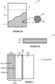
- FIGURES 2A-2B illustrate plan and cross-sectional views, respectively of metallic gas diffusion layer 112, according to certain embodiments.
- the cross-sectional view of FIGURE 2B is taken along a cross-section A-A' of FIGURE 2A .
- metallic gas diffusion layer 112 includes metal-containing layer 114 and a coating 116a of porous material deposited on a first surface of metal-containing layer 114, a portion of coating 116a having been removed (or not yet deposited, as the case may be) for illustrative purposes to reveal metal-containing layer 114.
- metal-containing layer 114 includes openings 202. Note that the content of magnified portion 200 may not correspond exactly to the content of the portion of metal-containing layer 114 shown to be magnified, and is meant for illustrative purposes only. The particular size and shape of openings 202 and metal-containing layer 114 are provided as examples only.
- a second coating 116b of porous material is deposited on a second surface of metal-containing layer 114.
- coatings 116a and 116b of porous material are shown to be discretely deposited on opposing respective surfaces of metal-containing layer 114, porous material of coatings 116a and/or 116b may be present within openings 202 of metal-containing layer 114.
- FIGURE 3 illustrates a magnified cross-sectional view of a portion of membrane electrode assembly 100 of FIGURE 1 , according to certain embodiments.
- the magnified view of FIGURE 3 includes a portion of electrode 102a and a portion of electrolyte membrane layer 106.
- a bonding material 300 may be positioned between electrolyte membrane layer 106 and electrode catalyst layer 110a to facilitate adhesion between electrolyte membrane layer 106 and electrode catalyst layer 110a, such as when some or all of the components of membrane electrode assembly 100 are pressed or otherwise coupled together to form a portion or all of membrane electrode assembly 100.
- a similar bonding material 300 may be present between electrolyte membrane layer 106 and electrode catalyst layer 110b (of FIGURE 1 ).
- bonding material 300 is a liquid ionomer, but bonding material 300 may including any suitable material.
- bonding material 300 may be a fluoropolymer such as a proton exchange membrane like NAFION manufactured by DUPONT, a bipolar exchange membrane like FUMASEP manufactured by FUMATECH BWT GMBH, or an anion exchange membrane like TOKUYAMA A201 manufactured by TOKUYAMA CORPORATION or AEMION manufactured by IONOMR INNOVATIONS INC.
- a fluoropolymer such as a proton exchange membrane like NAFION manufactured by DUPONT, a bipolar exchange membrane like FUMASEP manufactured by FUMATECH BWT GMBH, or an anion exchange membrane like TOKUYAMA A201 manufactured by TOKUYAMA CORPORATION or AEMION manufactured by IONOMR INNOVATIONS INC.
- FIGURES 4A-4B illustrate plan and cross-sectional views, respectively, of an example membrane electrode assembly 400, according to certain embodiments.
- Membrane electrode assembly 400 may be a particular implementation of membrane electrode assembly 100 of FIGURE 1 .
- the same reference numerals used to refer to aspects of membrane electrode assembly 100 are used to refer to aspects of membrane electrode assembly 400.
- the cross-sectional view of FIGURE 4B is taken along a cross-section B-B' of FIGURE 4A .
- a coating 116ab of porous material is deposited on a surface of metal-containing layer 114a of metallic gas diffusion layer 112a that faces away from electrolyte membrane layer 106 and electrode catalyst layer 110a.
- a coating 116bb of porous material is deposited on a surface of metal-containing layer 114b of metallic gas diffusion layer 112b that faces away from electrolyte membrane layer 106 and electrode catalyst layer 110b.
- a portion 404a of metal-containing layer 114a remains uncovered by porous material of coatings 116aa and 116ab.
- Portion 404a extends around a perimeter of metal-containing layer 114a.
- a portion 404b of metal-containing layer 114b remains uncovered by porous material of coatings 116ba and 116bb.
- Portion 404b extends around a perimeter of metal-containing layer 114b.
- a template e.g., similar to a stencil
- Metal-containing layers 114 of metallic gas diffusion layers 112 include respective tabs 402.
- metal-containing layer 114a of metallic gas diffusion layer 112a includes tab 402a
- metal-containing layer 114b of metallic gas diffusion layer 112b includes tab 402b.
- Tabs 402 may be used to contact another element of a fuel cell or other apparatus for carrying current and powering a device. In certain embodiments, tabs 402 may be used for carrying current in place of separate current collector plates for membrane electrode assembly 400.
- tabs 402a and 402b may be configured to electrically connect, directly or indirectly, to respective terminals of a fuel cell, each terminal having an associated polarity, the polarity of the terminals being opposite one another.
- Tabs 402 may have any suitable size and shape, according to particular implementations. Additionally, although tabs 402a and 402b are shown to extend from opposite sides of membrane electrode assembly 400, tabs 402a and 402b may extend from any particular side of membrane electrode assembly 400, and may extend from the same or different sides of membrane electrode assembly 400.
- membrane electrode assembly 400 may be suitable for relatively low power (e.g., in the hundreds of watts) fuel cells/fuel cell stacks.
- metal-containing layers 114 of membrane electrode assembly 400 may be made from composite plates, which may reduce overall weight, though at the possible expense of losing some conductivity.
- composite plates could include, for example, a graphite composite material.
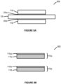
- FIGURES 5A-5B illustrate plan and cross-sectional views, respectively, of an example membrane electrode assembly 500, according to certain embodiments.
- Membrane electrode assembly 500 may be a particular implementation of membrane electrode assembly 100 of FIGURE 1 .
- the same reference numerals used to refer to aspects of membrane electrode assembly 100 are used to refer to aspects of membrane electrode assembly 500.
- the cross-sectional view of FIGURE 5B is taken along a cross-section C-C' of FIGURE 5A .
- elements of membrane electrode assembly 500 is positioned between a pair of current collectors 502a (on the side of electrode 102a) and 502b (on the side of electrode 102b).
- Current collector 502a overlies (at least in the orientation shown) metallic gas diffusion layer 112a.
- a perimeter of metal-containing layer 114a of metallic gas diffusion layer 112a is shown with dotted line segments in FIGURE 5A to illustrate that metal-containing layer 114a underlies (at least in the orientation shown) current collector 502a but to still provide some orientation to the additional features underlying current collector 502a that can be seen in the cross-sectional view of FIGURE 5B .
- Current collector 502b underlies (at least in the orientation shown) metallic gas diffusion layer 112b.
- Current collectors 502 are formed of conductive material to facilitate movement of current or electrons to and from membrane electrode assembly 500 such that a device can be powered, wholly or partially, by a fuel cell that incorporates membrane electrode assembly 500.
- current collector 502a may carry negatively-charged electrons from electrode 102a and current collector 502b may return negatively-charged electrons to electrode 102b.
- current collectors 502a and 502b may be configured to electrically connect, directly or indirectly, to respective terminals of a fuel cell, each terminal having an associated polarity, the polarity of the terminals being opposite one another.
- Current collectors 502 may be formed of any suitable type of conductive material.
- conductive material of current collectors 502 may include copper, aluminum, gold, a metallic alloy, or another conductive material.
- the type of conductive material for a current collector 502 may depend on a type of electrode 102 (e.g., anode or cathode) and/or on a type of fuel cell into which membrane electrode assembly 500 is being incorporated. That is, in certain embodiments, a current collector 502a for an anode (e.g., electrode 102a) may include a different conductive material than a current collector 502b for a cathode (e.g., electrode 102b).
- a pair of gaskets 504 may be used to seal certain components of membrane electrode assembly 500 between, in this example, current collectors 502.
- a gasket 504a may surround electrode 102a along a perimeter of electrode 102a and be sandwiched between current collector 502a and electrolyte membrane layer 106 to provide a seal for electrode 102a.
- a gasket 504b may surround electrode 102b along a perimeter of electrode 102b and be sandwiched between current collector 502b and electrolyte membrane layer 106 to provide a seal for electrode 102b.
- any suitable sealant mechanism may be used in place of gaskets 504.
- gaskets 504 are made of silicone rubber.
- no second coating 116 (e.g., second coating 116ab or 116bb) has been deposited on surfaces of metal-containing layers 114a and 114b that face away from electrode catalyst layers 110.
- This disclosure contemplates membrane electrode assembly 500 being implemented with a second coating 116 (e.g., second coating 116ab or 116bb) being deposited on surfaces of metal-containing layers 114a and 114b that face away from electrode catalyst layers 110, such that the second coatings 116 are positioned between current collectors 502 and metal-containing layers 114.
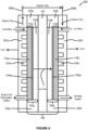
- FIGURE 6 illustrates an example fuel cell 600 that incorporates membrane electrode assembly 100 of FIGURE 1 , according to certain embodiments.
- Fuel cell 600 may be a complete power source (or at least a portion of a complete power source) or a fuel cell that is part of a larger collection of fuel cells (e.g., a stack of fuel cells) that collectively form a power source, for example.
- fuel cell 600 includes membrane electrode assembly 100, which includes electrode 102a (e.g., an anode) and electrode 102b (e.g., a cathode).
- electrode 102a and electrode 102b are primarily described as an anode and a cathode, respectively, this disclosure contemplates the polarity being reversed, if appropriate.
- Membrane electrode assembly 100 including some or all of its constituent parts, may be constructed using techniques described throughout this disclosure.
- electrolyte membrane layer 106 separates and electrically insulates electrode 102a from electrode 102b, which are disposed to opposing sides of electrolyte membrane layer 106. Additionally, electrolyte membrane layer 106 provides ion exchange (positive ions or anions, depending on the implementation of fuel cell 600) between electrode 102a and electrode 102b.
- Fuel cell 600 includes a pair of bipolar end plates 602a and 602b, which may be referred to generally as end plates 602.
- end plates 602 encase components of fuel cell 600, and may be provided to protect and insulate the internal components of fuel cell 600 (including, for example, membrane electrode assembly 100).
- a portion of end plates 602 may act as a current collector for collecting and transferring current generated using membrane electrode assembly 100.
- the current collectors could be provided as separate elements of fuel cell 600.
- end plates 602 each include a flow field 604 (flow field 604a for end plate 602a and flow field 604b for end plate 602b), which may be openings that provide a path for movement of fuel, air, water, or other suitable substances used or generated by fuel cell 600.
- Flow fields 604 also may be referred to as flow channels.
- end plates 602a and 602b include or are coupled to respective terminals 606a and 606b.
- end plate 602a which in this example is associated with electrode 102a (e.g., an anode) may be coupled to a terminal 606a having a first polarity (e.g., a negative polarity).
- end plate 602b which in this example is associated with electrode 102b (e.g., a cathode), may be coupled to a terminal 606b having a second polarity (e.g., a positive polarity) that is opposite the polarity of terminal 606a.
- end plates 602a and 602b may be configured to electrically connect, directly or indirectly, to respective terminals 606a and 606b of fuel cell 600, each terminal 606a and 606b having an associated polarity, the polarity of terminals 606a and 606b being opposite one another.
- terminal 606a and terminal 606b are primarily described as a negative terminal and a positive terminal, respectively, this disclosure contemplates the polarity being reversed, if appropriate.
- terminals 606a and 606b could be any suitable type of contact portion that could be coupled directly or via any suitable intervening conductive structure, to terminals of fuel cell 600 or a collection of fuel cells of which fuel cell 600 is a part. Furthermore, although terminals 606a and 606b are shown to extend from a same end of fuel cell 600, terminals 606a could extend from fuel cell 600 in a first direction, while terminal 606b could extend from fuel cell 600 in a different (and not necessarily opposite) direction.
- End plate 602a may include a fuel inflow opening through which a fuel (e.g., hydrogen, ethanol, etc.) may be injected into fuel cell 600 for processing, at least initially, by electrode 102a. As illustrated, end plate 602a also may include an outflow opening. Surplus fuel may be recirculated to the fuel inflow opening of end plate 602a, if desired. Additionally or alternatively, other reaction byproducts may be output through the outflow opening of end plate 602a. In certain embodiments, flow field 604a provides a flow path between the inflow opening and the outflow opening of end plate 602a.
- a fuel e.g., hydrogen, ethanol, etc.
- End plate 602b may include an inflow opening through which air or another suitable substance may be injected into fuel cell 600 for processing, at least initially, by electrode 102b. As illustrated, end plate 602b also may include an outflow opening. Air, water, and/or other reactant byproducts may be expelled from fuel cell 600 through the outflow opening of end plate 602b, if desired. In certain embodiments, flow field 604b provides a flow path between the inflow opening and the outflow opening of end plate 602b.
- a pair of gaskets 608 may be used to seal certain components of membrane electrode assembly 100 between, in this example, end plates 602.
- a gasket 608a may surround electrode 102a along a perimeter of electrode 102a and be sandwiched between end plate 602a and electrolyte membrane layer 106 to provide a seal for electrode 102a.
- a gasket 608b may surround electrode 102b along a perimeter of electrode 102b and be sandwiched between end plate 602b and electrolyte membrane layer 106 to provide a seal for electrode 102b.
- any suitable sealant mechanism may be used in place of gaskets 608.
- gaskets 608 are made of silicone rubber. Gaskets 608 may be similar to gaskets 504 described above with reference to membrane electrode assembly 500.
- End plates 602 may be formed of any suitable material. To the extent end plates 602 play a role in conductive features of fuel cell 600, at least a portion of end plates 602 are made of a conductive material. For example, to the extent end plates 602 incorporate a current collector, the above discussion of example materials for current collectors 502 of membrane electrode assembly 500 (described with reference to FIGURE 5 ) is incorporated by reference. As just a few particular examples, end plates 602 could be made wholly or partially of graphite or metal, such as stainless steel, aluminum, titanium, or the like. Additionally, end plates 602 may have any suitable size and shape.
- fuel cell 600 may include additional casing components to further encase the illustrated elements of fuel cell 600.
- the additional casing components may encase components of fuel cell 600, and may be provided to protect and insulate the internal components of fuel cell 600 (including, for example, membrane electrode assembly 100). Additionally or alternatively, when fuel cell 600 is part of a collection of fuel cells, the collection of fuel cells may be encased with a suitable casing.
- the current collector of fuel cell 600 may be connected to one or more current aggregation elements (e.g., a shared conductive bus bar for the anodes and a shared conductive bus bar for the cathodes).
- Terminals 606a and 606b may be positioned, at least partially, external to the additional casing and/or may be at least partially integral to the additional casing.
- the additional casing may be formed of an insulating material, polymer, shrink wrap, or the like, and may be hard or soft, and which is appropriate may depend on a form factor of fuel cell 600. It should be understood that fuel cell 600 and any additional casing into which fuel cell 600 is incorporated may take any suitable form factor.
- end plate 602a receives a fuel at the fuel inflow, and the fuel passes along an interface of metallic gas diffusion layer 112a of electrode 102a.
- a fuel for fuel cell 600 may include hydrogen, ethanol, or a variety of other possible fuels.
- a portion of the fuel that is not processed by metallic gas diffusion layer 112a may be recirculated at a recirculation outflow.
- metallic gas diffusion layer 112a may facilitate distribution of the fuel (e.g., hydrogen gas) along an interface of metallic gas diffusion layer 112a and electrode catalyst layer 110a.
- Electrode catalyst layer 110a may facilitate a reaction to occur (e.g., an oxidation reaction) in which some or all of the fuel is separated into electrons and positively-charged ions.
- Metallic gas diffusion layer 112a may facilitate movement of the electrons to a terminal (e.g., an anode terminal 606a), directly or indirectly, and possibly via a current collector, for use in powering a device.
- Electrode catalyst layer 110a, electrolyte membrane layer 106, and electrode catalyst layer 110b are configured to conduct the positively-charged ions (or anions, as may be the case for particular implementations) such that the positively-charged ions (or anions, as may be the case for particular implementations) travel across electrolyte membrane layer 106 from electrode 102a to electrode 102b.
- the electrons reenter the fuel cell through another terminal (e.g., a cathode terminal 606b) and are returned to metallic gas diffusion layer 112b of electrode 102b, directly or indirectly, and possibly via a current collector.
- Metallic gas diffusion layer 112b may assist in transporting the electrons and a reactant gas to electrode catalyst layer 110b, which facilitates a reaction involving the electrons, the positively-charged ions (or anions, as may be the case for particular implementations), and the reactant gas to form a byproduct, such as water.
- the reactant gas may be oxygen, which may be continuously provided through an inflow of air.
- FIGURES 7A-7F illustrate an example process 700 for forming a membrane electrode assembly, according to certain embodiments.
- process 700 may be used to form membrane electrode assembly 100, membrane electrode assembly 400, or membrane electrode assembly 500.
- metal-containing layers 114a and 114b are provided.
- metal-containing layer 114a is being formed into an anode (e.g., electrode 102a) and that metal-containing layer 114b is being formed into a cathode (e.g., electrode 102b).
- metal-containing layers 114 may be cut into the desired size and shape prior to further processing (or may come in the desired size and shape), or may be cut into the desired size and shape at a subsequent processing stage.
- Metal-containing layers 114a and 114b may be prepared for further processing.
- preparing metal-containing layers 114a and 114b includes cleaning metal-containing layers 114a and 114b.
- metal-containing layers 114a and 114b may be washed in acid or another suitable substance to reduce or eliminate surface oxides and/or other impurities.
- Example acids include hydrochloric acid and sulfuric acid.
- metal-containing layers 114a and 114b may be rinsed in deionized water or another suitable substance to reduce or eliminate acid and salts. Rinsing may reduce the opportunity for the acid or removed materials to leach into the catalyst layer in a subsequent step.
- metal-containing layers 114a and 114b may be dried, such as through baking in an oven. As just one example, the oven may be a muffle furnace.
- a first coating 116aa of porous material may be applied to a first surface of metal-containing layer 114a and a first coating 116ba of porous material may be applied to a first surface of metal-containing layer 114b.
- the surfaces of metal-containing layers 114a and 114b to which the first coatings 116aa and 116ba are respectively applied are the surfaces that ultimately will face respective electrode catalyst layers 110a and 110b.
- the combination of metal-containing layer 114a and first coating 116aa of porous material forms metallic gas diffusion layer 112a, which is to be part of electrode 102a
- the combination of metal-containing layer 114b and first coating 116ba of porous material forms metallic gas diffusion layer 112b, which is to be part of electrode 102b.
- applying first coating 116aa of porous material to the first surface of metal-containing layer 114a includes heating metal-containing layer 114a and applying a porous layer ink on the first surface of metal-containing layer 114a to form first coating 116aa of porous material.
- applying first coating 116ba of porous material to the first surface of metal-containing layer 114b may include heating metal-containing layer 114b and applying a porous layer ink on the first surface of metal-containing layer 114b to form first coating 116ba of porous material.
- each metal-containing layer 114a and 114b may be positioned on a hot plate or other heating apparatus and heated to suitable temperature.
- first coatings 116aa and 116ba are applied to the heated metal-containing layers 114a and 114b by spraying, using an air-brush, in substantially uniform strokes, the porous material to the first surfaces of metal-containing layers 114a and 114b.
- the air brush used to apply first coatings 116aa and 116ba of the porous material to metal-containing layers 114a and 114b may be a hand-held spray brush or may be part of a machine, such as a slot die coater. Applying first coatings 116aa and 116ba while metal-containing layers 114a and 114b are at an elevated temperature may facilitate applying a uniform smooth coating of porous material to metal-containing layers 114a and 114b.
- the porous material of coatings 116aa and 116ba is formed using a porous ink that is a slurry formed from a powder, a hydrophobic binder, and (during deposition) a solvent.
- the powder may include a carbon powder (e.g., a high surface area carbon black or activated carbon of various forms).
- a carbon powder e.g., a high surface area carbon black or activated carbon of various forms.
- Examples of carbon powders are BLACK PEARLS currently manufactured by CABOT CORPORATION and KETJENBLACK manufactured by AKZO NOBEL N.V.
- the binder may act as an adhesive that helps the porous material rest on the surface to which the porous ink is applied, in this case the first surface of a metal-containing layer 114.
- the binder may help hold particles of the powder together to form coatings 116a and 116ba.
- the binding agent may be a hydrophobic binder and may include PTFE.
- PTFE is TEFLON currently manufactured by THE CHEMOURS COMPANY.
- the binding agent may be inert.
- the powder and hydrophobic binder (and potentially other components of the porous material of coatings 116) are mixed using a solvent.
- the solvent may liquify the combination of these components for deposition.
- Example solvents include dimethyl sulfoxide (DMSO), ethanol, isopropyl alcohol, and the like.
- the components of the porous material may contribute to the performance of metallic gas diffusion layer of the membrane electrode assembly being formed.
- the various ratios of the components relative to one another may be selected to achieve an optimal combination of properties of the metallic gas diffusion layer and associated membrane electrode assembly.
- the selection of solvent may affect which binding agents are suitable, and possibly whether additional additives are appropriate.
- porous material is described as including this particular content or taking this particular form or being deposited in particular manners, this disclosure contemplates the porous material including any suitable content and taking any suitable form and being deposited in any suitable manner.
- the porous material of coatings 116 may be deposited using dry deposition techniques, if desired, and therefore the solvent may be omitted in such embodiments.
- Porous material may be applied to the first surfaces of metal-containing layers 114a and 114b until a target loading of porous material is reached.
- the content (e.g., the porous material) and/or thickness of coatings 116aa and 116ba of porous materials may be the same or different.
- coatings 116aa and 116ba may have any suitable thickness, in certain embodiments, coatings 116aa and 116ba are about 2 ⁇ m to about 10 ⁇ m thick, potentially depending on the fuel and oxidizer to be used, and on the porosity and density of networks formed, and may have the same or different thicknesses relative to one another.
- coatings 116aa and 116ba may have any suitable area density
- target areal densities for coatings 116aa and 116ba are about 4 mg/cm 2 to about 7 mg/cm 2 , and may have the same or different areal densities relative to one another.
- applying first coating 116aa of porous material to the first surface of metal-containing layer 114a may include heating metal-containing layer 114a
- applying first coating 116ba of porous material to the first surface of metal-containing layer 114b may include heating metal-containing layer 114b.
- Heating metal-containing layers 114a and 114b may dry the porous materials of coatings 116aa and 116ba, respectively.
- the porous materials of coatings 116aa and 116ba include a solvent
- heating metal-containing layers 114a and 114b may include drying, or evaporating, the solvent, which in turn may dry the porous materials of coatings 116aa and 116ba.
- the appropriate temperature for heating metal-containing layers 114a and 114b during application of coatings 116aa and 116ba, respectively, of porous material, as well as the time of exposure to the heat, may be specific to the surface area of the surfaces of metal-containing layers 114a and 114b to which coatings 116aa and 116ba, respectively, are being applied.
- the temperature may be about 10°C to about 30°C above the boiling point of the solvent in the porous material, and for purposes of drying coatings 116aa and 116ba of porous material, metal-containing layers 114a and 114b may be heated for about 20 minutes to about 40 minutes.
- the suitable temperature is about 50°C to about 100°C, and in a particular example is about 80°C. It should be understood, however, that the particular temperature may depend on the materials involved and a variety of other factors.
- the combination of metal-containing layer 114a and coating 116aa of porous material on a surface of metal-containing layer 114a to face a subsequently-deposited electrode catalyst material may be considered a metallic gas diffusion layer 112a for an anode (e.g., electrode 102a of membrane electrode assembly 100).
- the combination of metal-containing layer 114b and coating 116ba of porous material on a surface of metal-containing layer 114b to face a subsequently-deposited electrode catalyst material may be considered a metallic gas diffusion layer 112b for a cathode (e.g., electrode 102b of membrane electrode assembly 100).
- an electrode catalyst layer 110a is deposited on first coating 116aa of porous material of metal-containing layer 114a (e.g., metallic gas diffusion layer 112a), and an electrode catalyst layer 110b is deposited on first coating 116ba of porous material of metal-containing layer 114b (e.g., metallic gas diffusion layer 112b).
- depositing electrode catalyst layer 110a on first coating 116aa of porous material of metal-containing layer 114a includes heating metal-containing layer 114a and applying a catalyst ink on first coating 116aa.
- depositing electrode catalyst layer 110b on first coating 116ba of porous material of metal-containing layer 114b may include heating metal-containing layer 114b and applying a catalyst ink on first coating 116ba.
- each metal-containing layer 114a and 114b may be positioned on a hot plate or other heating apparatus and heated to suitable temperature.
- electrode catalyst layers 110a and 110b are deposited to the heated metal-containing layers 114a and 114b by spraying, using an air-brush, in substantially uniform sweeps, the electrode catalyst material to a surface of first coating 116aa of porous material of metal-containing layer 114a and to a surface of first coating 116ba of porous material of metal-containing layer 114b, and allowing the deposited electrode catalyst material to dry while on the hot plate.
- the air brush used to apply the catalyst material on first coatings 116aa and 116ba of the porous material may be a hand-held spray brush or may be part of a machine, such as a slot die coater.
- the electrode catalyst material of electrode catalyst layers 110a and 110b is formed using an electrode catalyst ink that is a slurry formed from a powder, a binder, and (during deposition) a solvent.
- the powder may include a powder of a suitable material for the electrode being formed (e.g., anode or cathode) in view of the type of fuel cell being formed.
- the material of electrode catalyst layer 110 may include a catalyst material and an ion-conducting polymer (e.g., an ionomer), and may facilitate the splitting of the fuel (e.g., hydrogen) into protons and electrons.
- the material of electrode catalyst layer 110 may include a catalyst material and an ion-conducting polymer (e.g., an ionomer), and may facilitate the reduction of the oxygen by reacting with the protons resulting from the splitting of the fuel (e.g., hydrogen) by the anode (and passing through electrolyte membrane layer 106) to produce water or another suitable byproduct.
- an ion-conducting polymer e.g., an ionomer
- the catalyst material of electrode catalyst layers 110 may include platinum, platinum alloys with transition metals, platinum-ruthenium alloy, platinum de-alloy, palladium, core-shell, non-precious metal, shape-controlled nanocrystals, extended platinum surfaces, nanoframes, or other materials/structures, and may be in black (or pure) form or a supported form. In supported form, the support material may include carbon or another suitable material. As just a few examples, the catalyst material may be platinum-on-carbon or ruthenium-on-carbon. The ionomer(s) in each electrode catalyst layers 110 may facilitate the movement of protons through electrode catalyst layers 110.
- the binder may act as an adhesive that helps electrode catalyst ink rest on the surface to which the electrode catalyst ink is deposited.
- the binder may help hold particles of the powder together to form electrode catalyst layers 110a and 110b.
- the binding agent may be a fluoropolymer such as a proton exchange membrane like NAFION manufactured by DUPONT, a bipolar exchange membrane like FUMASEP manufactured by FUMATECH BWT GMBH, or an anion exchange membrane like TOKUYAMA A201 manufactured by TOKUYAMA CORPORATION or AEMION manufactured by IONOMR INNOVATIONS INC.
- the powder and binder (and potentially other components of the electrode catalyst ink of electrode catalyst layers 110) are mixed using a solvent.
- the solvent may liquify the combination of these components for deposition.
- Example solvents include DMSO, ethanol, isopropyl alcohol, and the like.
- the components of the electrode catalyst layers 110 may contribute to the performance of electrodes 102, and thereby to the performance of membrane electrode assembly 100.
- the various ratios of the components relative to one another may be selected to achieve an optimal combination of properties of membrane electrode assembly 100.
- the selection of solvent may affect which binding agents are suitable, and possibly whether additional additives are appropriate.
- electrode catalyst layers 110 are described as including particular content or taking a particular form or being deposited in particular manners, this disclosure contemplates electrode catalyst layers 110 including any suitable content, taking any suitable form, and being deposited in any suitable manner.
- electrode catalyst layers 110 may be deposited using dry deposition techniques, and therefore the solvent may be omitted in such embodiments.
- Electrode catalyst ink may be deposited until a target loading for an electrode catalyst layer 110 is achieved.
- the content and/or thickness of electrode catalyst layers 110 may be the same or different.
- electrode catalyst layers 110a and 110b may have any suitable thickness, in certain embodiments, electrode catalyst layers 110a and 110b are about 2 ⁇ m to about 8 ⁇ m thick, potentially depending on the fuel and oxidizer to be used, and on the porosity and density of networks formed, and may have the same or different thicknesses relative to one another.
- electrode catalyst layers 110 may have any suitable areal density, in certain embodiments, electrode catalyst layers have an areal density of about 4 mg/cm 2 to about 8 mg/cm 2 , and may have the same or different areal densities relative to one another.
- depositing electrode catalyst layer 110a on first coating 116aa of porous material of metal-containing layer 114a may include heating metal-containing layer 114a and depositing electrode catalyst layer 110a on first coating 116aa of porous material
- depositing electrode catalyst layer 110b on first coating 116ba of porous material of metal-containing layer 114b may include heating metal-containing layer 114b and depositing electrode catalyst layer 110b on first coating 116ba of porous material.
- Heating metal-containing layers 114a and 114b may dry the electrode catalyst inks of electrode catalyst layers 110a and 110b, respectively.
- heating metal-containing layers 114a and 114b may include drying, or evaporating, the solvent, which in turn may dry the electrode catalyst inks of electrode catalyst layers 110a and 110b.
- the appropriate temperature for heating metal-containing layers 114a and 114b during application of electrode catalyst layers 110a and 110b, respectively, as well as the heat exposure time may be specific to the surface area of the surfaces of metal-containing layers 114a and 114b to which the electrode catalyst layers 110a and 110b are being applied.
- the temperature may be about 10°C to about 30°C above the boiling point of the solvent in the electrode catalyst inks, and for purposes of drying the electrode catalyst inks of electrode catalyst layers 110a and 110b, metal-containing layers 114a and 114b may be heated for about 20 minutes to about 40 minutes.
- the suitable temperature is about 50°C to about 100°C, and in a particular example is about 80°C. The particular temperature, however, may depend on the materials involved and a variety of other factors.
- metal-containing layers 114a and 114b may be positioned on a hot plate for the heating associated with depositing and drying of the porous material of coatings 116aa and 116ba, respectively, and then left on the hot plate for depositing and drying of electrode catalyst layers 110a and 110b.
- the porous material of a coating 116aa or 116ba may be allowed to dry prior to depositing and drying electrode catalyst layers 110a and 110b. If applicable, suitable temperature adjustments may be made. For example, the heat may be increased or decreased for depositing the electrode catalyst layers 110a and 110b, if appropriate.
- the combination of metallic gas diffusion layer 112a and electrode catalyst layer 110a may be considered an anode (e.g., electrode 102a of membrane electrode assembly 100).
- the combination of metallic gas diffusion layer 112b and electrode catalyst layer 110b may be considered a cathode (e.g., electrode 102b of membrane electrode assembly 100).
- a bonding material 300a may be deposited on electrode catalyst layer 110a, and a bonding material 300b may be deposited on electrode catalyst layer 110b.
- Bonding material 300a and 300b may facilitate adhesion between electrolyte membrane layer 106 and electrode catalyst layers 110a and 110b, respectively, such as in a subsequent step when electrodes 102a and 102b and electrolyte membrane layer 106 (shown in subsequent FIGURES 7E-7F ) are pressed or otherwise coupled together to form a portion or all of a membrane electrode assembly (e.g., a membrane electrode assembly 100).
- bonding material 300 is a liquid ionomer, but bonding material 300 may including any suitable material.
- bonding material 300 may be a fluoropolymer such as a proton exchange membrane like NAFION manufactured by DUPONT, a bipolar exchange membrane like FUMASEP manufactured by FUMATECH BWT GMBH, or an anion exchange membrane like TOKUYAMA A201 manufactured by TOKUYAMA CORPORATION or AEMION manufactured by IONOMR INNOVATIONS INC.
- Bonding material 300a and bonding material 300b may be the same or different, according to particular implementations.
- metallic gas diffusion layer 112a and electrode catalyst layer 110a are coupled to a first side of electrolyte membrane layer 106 and metallic gas diffusion layer 112b and electrode catalyst layer 110b are coupled to a second side of electrolyte membrane layer 106.
- metallic gas diffusion layer 112a and electrode catalyst layer 110a positioned to a first side of electrolyte membrane layer 106 and metallic gas diffusion layer 112b and electrode catalyst layer 110b positioned to a second side of electrolyte membrane layer 106
- metallic gas diffusion layer 112a, electrode catalyst layer 110a, electrolyte membrane layer 106, electrode catalyst layer 110b, and metallic gas diffusion layer 112b may be pressed together using a hot press or other suitable pressing tool.
- the layers may be pressed together (e.g., in directions 702a and 702b) until the layers bond to form a layer stack, the layer stack being membrane electrode assembly 100.
- This disclosure contemplates coupling the layers using any suitable technique.
- electrode catalyst layer 110a is positioned between metallic gas diffusion layer 112a and electrolyte membrane layer 106 to the first side of electrolyte membrane layer 106 and electrode catalyst layer 110b is positioned between metallic gas diffusion layer 112b and electrolyte membrane layer 106 to the second side of the electrolyte membrane layer 106.
- electrode 102a and electrode 102b are pressed to opposing sides of electrolyte membrane layer 106, in directions 702a and 702b, such that electrolyte membrane layer 106 is positioned between electrode 102a and electrode 102b.
- This disclosure contemplates any suitable intervening layers.
- metallic gas diffusion layer 112a, electrode catalyst layer 110a, electrolyte membrane layer 106, and metallic gas diffusion layer 112b, electrode catalyst layer 110b are coupled together using a hydraulic heat press tool. Plates of the heat press tool used for performing the pressing may made of any suitable material. In certain embodiments, the plates may include PTFE, aluminum, or another suitable material.
- metallic gas diffusion layer 112a and electrode catalyst layer 110a e.g., electrode 102a
- metallic gas diffusion layer 112b and electrode catalyst layer 110b e.g., electrode 102b
- the pressure may be about 3 megapascal (mPa) to about 7 mPa (and about 5mPa in a more particular example)
- the temperature may be about 90°C to about 130°C (and about 110°C to about 120°C in a more particular example)
- the time may be about 5 minutes to about 15 minutes (and about 10 minutes in a more particular example).
- the temperature for the hot press may be based on the glass transition temperature of the polymer being used for electrolyte membrane layer 106, such as about 25°C less than the glass transition temperature of the polymer in a particular example.
- the particular parameters for performing the pressing may depend on a variety of factors, including potentially the tool used to perform the hot pressing, the materials of electrodes 102a and 102b, the material of electrolyte membrane layer 106, the material of bonding material 300 (if used), and possible other factors.
- the combination of electrode 102a, electrolyte membrane layer 106, and electrode 102b may be considered a membrane electrode assembly 100.
- second coatings 116ab and 116bb of porous material may be deposited on another surface of metal-containing layers 114a and 114b, respectively, of metallic gas diffusion layers 112a and 112b.
- a second coating 116ab of porous material may be deposited on a surface of metal-containing layer 114a that faces away from electrode catalyst layer 110a of electrode 102a.
- a second coating 116bb of porous material may be deposited on a surface of metal-containing layer 114b that faces away from electrode catalyst layer 110b of electrode 102b.
- Second coatings 116ab and 116bb of porous material may be deposited in a similar manner to that of first coatings 116aa and 116ba, as described above with reference to FIGURE 7B , the details of which are incorporated by reference. In certain embodiments and for certain applications, adding second coatings 116ab and 116bb may provide for improved gas transport by metallic gas diffusion layers 112a and 112b.
- a template e.g., similar to a stencil
- portions 404 of metal-containing layers 114 remain uncovered by coatings 116 (e.g., portions 404 of metal-containing layers 114, as described above with reference to FIGURES 4A-4B .
- FIGURES 8A-8D illustrate an example process 800 for forming a membrane electrode assembly, according to certain embodiments.
- process 800 may be used to form membrane electrode assembly 100, membrane electrode assembly 400, or membrane electrode assembly 500.
- electrode catalyst layers 110a and 110b are combined with metallic gas diffusion layers 112a and 112b, respectively, prior to being combined with electrolyte membrane layer 106.
- electrode catalyst layers 110a and 110b are combined with respective opposing surfaces of electrolyte membrane layer 106 prior to combining the resulting combined structure with metallic gas diffusion layers 112a and 112b.
- At least portions of process 800 may correspond to a CCM technique. Portions of process 800 may correspond or otherwise be similar to portions of process 700 described above with reference to FIGURES 7A-7F .
- electrode catalyst layers 110a and 110b are formed on respective opposing surfaces of electrolyte membrane layer 106.
- electrode catalyst layer 110a is formed on a first surface of electrolyte membrane layer 106
- electrode catalyst layer 110b is formed on an opposing second surface of electrolyte membrane layer 106.
- the combined structure of electrolyte membrane layer 106 and electrode catalyst layers 110a/110b may be purchased from a suitable supplier or may be formed as part of the process for forming membrane electrode assembly 100.
- electrolyte membrane layer 106 and electrode catalyst layers 110a/110b are formed as part of process 800 (e.g., rather than purchased as a combined structure)
- this disclosure contemplates coupling electrode catalyst layers 110a and 110b to the opposing surfaces of electrolyte membrane layer 106 in any suitable manner.
- electrode catalyst layers 110a and 110b may be coupled to the opposing surfaces of electrolyte membrane layer 106 by performing a hot-press technique similar to that described above with reference to FIGURE 7E (e.g., in connection with pressing gas diffusion layer 112a, electrode catalyst layer 110a, electrolyte membrane layer 106, electrode catalyst layer 110b, and gas diffusion layer 112b together).
- a hot-press technique similar to that described above with reference to FIGURE 7E (e.g., in connection with pressing gas diffusion layer 112a, electrode catalyst layer 110a, electrolyte membrane layer 106, electrode catalyst layer 110b, and gas diffusion layer 112b together).
- bonding material 300a may be deposited on electrode catalyst layer 110a
- bonding material 300b may be deposited on electrode catalyst layer 110b. Bonding material 300a and 300b may facilitate adhesion between electrolyte membrane layer 106 and electrode catalyst layers 110a and 110b, respectively.
- electrode catalyst layers 110a and 110b may be deposited on opposing surfaces of electrolyte membrane layer 106 by performing a deposition technique similar to that described above with reference to FIGURE 7C (e.g., in connection with depositing electrode catalyst layer 110a on coating 116aa of porous material on metal-containing layer 114a and depositing electrode catalyst layer 110b on coating 116ba of porous material on metal-containing layer 114b).
- a deposition technique similar to that described above with reference to FIGURE 7C (e.g., in connection with depositing electrode catalyst layer 110a on coating 116aa of porous material on metal-containing layer 114a and depositing electrode catalyst layer 110b on coating 116ba of porous material on metal-containing layer 114b).
- FIGURE 7C The description of such depositing from FIGURE 7C is incorporated by reference.
- Electrode catalyst layers 110a and 110b are to cover only a portion of electrolyte membrane layer 106, a template may be used when depositing electrode catalyst layers 110a and 110b on opposing surfaces of electrolyte membrane layer 106 to control the area of deposition.
- metal-containing layers 114a and 114b are provided, and a first coating 116aa of porous material is applied to a first surface of metal-containing layer 114a and a first coating 116ba of porous material is applied to a first surface of metal-containing layer 114b.
- the techniques associated with FIGURE 8B may be similar to those described in connection with FIGURES 7A-7B . Thus, the description of FIGURES 7A-7B are incorporated by reference.
- the combination of metal-containing layer 114a and coating 116aa of porous material on a surface of metal-containing layer 114a to face an electrode catalyst layer 110a may be considered a metallic gas diffusion layer 112a for an anode (e.g., electrode 102a of membrane electrode assembly 100).
- the combination of metal-containing layer 114b and coating 116ba of porous material on a surface of metal-containing layer 114b to face an electrode catalyst layer 110b may be considered a metallic gas diffusion layer 112b for a cathode (e.g., electrode 102b of membrane electrode assembly 100).
- metallic gas diffusion layer 112a is coupled to a first side of the combined structure (e.g., the combined structure including electrode catalyst layer 110a to a first side of electrolyte membrane layer 106 and electrode catalyst layer 110b to a second side of electrolyte membrane layer 106) and metallic gas diffusion layer 112b is coupled to a second side of the combined structure (e.g., the combined structure including electrode catalyst layer 110a to a first side of electrolyte membrane layer 106 and electrode catalyst layer 110b to a second side of electrolyte membrane layer 106).
- metallic gas diffusion layer 112a positioned to a first side of the combined structure and metallic gas diffusion layer 112b positioned to a second side of the combined structure
- metallic gas diffusion layer 112a, the combined structure, and metallic gas diffusion layer 112b may be pressed together, in directions 802a and 802b, using a hot press or other suitable pressing tool.
- the layers may be pressed together until the layers bond to form a layer stack, the layer stack being the membrane electrode assembly (e.g., membrane electrode assembly 100).
- This disclosure contemplates coupling the layers using any suitable technique.
- electrode catalyst layer 110a is positioned between metallic gas diffusion layer 112a and electrolyte membrane layer 106 to the first side of electrolyte membrane layer 106 and electrode catalyst layer 110b is positioned between metallic gas diffusion layer 112b and electrolyte membrane layer 106 to the second side of the electrolyte membrane layer 106.
- metallic gas diffusion layer 112a may be coupled together by performing a hot-press technique similar to that described above with reference to FIGURE 7E (e.g., in connection with pressing gas diffusion layer 112a, electrode catalyst layer 110a, electrolyte membrane layer 106, electrode catalyst layer 110b, and gas diffusion layer 112b together).
- a hot-press technique similar to that described above with reference to FIGURE 7E (e.g., in connection with pressing gas diffusion layer 112a, electrode catalyst layer 110a, electrolyte membrane layer 106, electrode catalyst layer 110b, and gas diffusion layer 112b together).
- the combination of metallic gas diffusion layer 112a and electrode catalyst layer 110a may be considered an anode (e.g., electrode 102a of membrane electrode assembly 100).
- the combination of metallic gas diffusion layer 112b and electrode catalyst layer 110b may be considered a cathode (e.g., electrode 102b of membrane electrode assembly 100).
- the combination of electrode 102a, electrolyte membrane layer 106, and electrode 102b may be considered a membrane electrode assembly 100.
- second coatings 116ab and 116bb of porous material may be deposited on another surface of metal-containing layers 114a and 114b, respectively, of metallic gas diffusion layers 112a and 112b.
- the deposition of second coatings 116ab and 116bb may be performed in a similar manner to that described above with reference to FIGURE 7F .
- FIGURE 7F the description of FIGURE 7F is incorporated by reference.
- processes 700 and 800 although forming single electrodes 102a and 102b (and their respective constituent layers) and electrolyte membrane layer 106 has been referenced, this disclosure contemplates forming electrodes 102 (and/or any of their constituent layers), electrolyte membrane layer 106, and/or membrane electrode assembly 100 having a large enough area to accommodate, forming multiple electrodes 102 (and/or any of their constituent layers), electrolyte membrane layers 106, and/or membrane electrode assemblies 100 in a sheet and then subsequently cutting the formed sheet into separate electrodes 102 (and/or any of their constituent layers), electrolyte membrane layers 106, and/or membrane electrode assemblies 100. Additionally or alternatively, processes 700 and/or 800 may be repeated to form additional membrane electrode assemblies and/or fuel cells.
- FIGURE 9 illustrates an example method 900 for forming a membrane electrode assembly (e.g., membrane electrode assembly 100) and associated fuel cell, according to certain embodiments.
- method 900 is generally analogous to process 700.
- first metallic gas diffusion layer 112a and second metallic gas diffusion layer 112b are formed.
- block 902 may include, at block 902(a), providing a metal-containing layer 114 (e.g., metal-containing layer 114a or 114b) and, at block 902(b), applying a first coating (first coating 116aa or first coating 116ba) of porous material on a first surface of the metal-containing layer 114.
- first coating first coating 116aa or first coating 116ba
- the metal-containing layer 114a or 114b is prepared prior to applying the first porous coating on the first surface of the metal-containing layer 114a or 114b.
- Preparing metal-containing layers 114a and 114b may include cleaning metal-containing layers 114a and 114b.
- metal-containing layers 114a and 114b may be washed in acid or another suitable substance to reduce or eliminate surface oxides and/or other impurities.
- metal-containing layers 114a and 114b may be rinsed in deionized water or another suitable substance to reduce or eliminate acid and salts.
- metal-containing layers 114a and 114b may be dried, such as through baking in an oven.
- block 902 generally corresponds to FIGURES 7A-7B (and associated portions of process 700), the details of which are incorporated by reference.
- the combination of metal-containing layer 114a and coating 116aa of porous material on a surface of metal-containing layer 114a to face a subsequently-deposited electrode catalyst layer 110a may be considered a metallic gas diffusion layer 112a for an anode (e.g., electrode 102a).
- the combination of metal-containing layer 114b and coating 116ba of porous material on a surface of metal-containing layer 114b to face a subsequently-deposited electrode catalyst layer 110b may be considered a metallic gas diffusion layer 112b for a cathode (e.g., electrode 102b).
- electrode catalyst layer 110a is deposited on first coating 116aa of porous material of metal-containing layer 114a (e.g., metallic gas diffusion layer 112a), and at block 906, electrode catalyst layer 110b is deposited on first coating 116ba of porous material of metal-containing layer 114b (e.g., metallic gas diffusion layer 112b).
- blocks 904 and 906 generally correspond to FIGURE 7C (and the associated portions of process 700), the details of which are incorporated by reference.
- metallic gas diffusion layer 112a and electrode catalyst layer 110a are coupled to a first side of electrolyte membrane layer 106 and metallic gas diffusion layer 112b and electrode catalyst layer 110b (e.g., electrode 102b) are coupled to a second side of electrolyte membrane layer 106.
- metallic gas diffusion layer 112a and electrode catalyst layer 110a e.g., collectively, electrode 102a
- metallic gas diffusion layer 112b and electrode catalyst layer 110b e.g., collectively, electrode 102b
- metallic gas diffusion layer 112a, electrode catalyst layer 110a, electrolyte membrane layer 106, electrode catalyst layer 110b, and metallic gas diffusion layer 112b may be pressed together using a hot press or other suitable pressing tool.
- the layers may be pressed together until the layers bond to form a layer stack, the layer stack being the membrane electrode assembly (e.g., membrane electrode assembly 100).
- This disclosure contemplates coupling the layers using any suitable technique.
- electrode catalyst layer 110a is positioned between metallic gas diffusion layer 112a and electrolyte membrane layer 106 to the first side of electrolyte membrane layer 106 and electrode catalyst layer 110b is positioned between metallic gas diffusion layer 112b and electrolyte membrane layer 106 to the second side of the electrolyte membrane layer 106.
- electrode 102a and electrode 102b are pressed to opposing sides of electrolyte membrane layer 106, in directions 702a and 702b, such that electrolyte membrane layer 106 is positioned between electrode 102a and electrode 102b.
- a bonding material 300a may be deposited on electrode catalyst layer 110a, and a bonding material 300b may be deposited on electrode catalyst layer 110b. Bonding material 300a and 300b may facilitate adhesion between electrolyte membrane layer 106 and electrode catalyst layers 110a and 110b, respectively, when electrodes 102a and 102b and electrolyte membrane layer 106 are pressed together to form a portion or all of a membrane electrode assembly (e.g., a membrane electrode assembly 100).
- a membrane electrode assembly e.g., a membrane electrode assembly 100
- block 908 as well of the possibility of applying bonding material 300a/300b, generally correspond to FIGURES 7D-7E (and the associated portions of process 700), the details of which are incorporated by reference.
- the combination of electrode 102a, electrolyte membrane layer 106, and electrode 102b may be considered a membrane electrode assembly 100.
- a second coating 116ab of porous material is deposited on another surface of metal-containing layer 114a of metallic gas diffusion layer 112a, and at block 912, a second coating 116bb of porous material is deposited on another surface of metal-containing layer 114b of metallic gas diffusion layer 112b.
- a second coating 116ab of porous material may be deposited on a surface of metal-containing layer 114a that faces away from electrode catalyst layer 110a of electrode 102a.
- a second coating 116bb of porous material may be deposited on a surface of metal-containing layer 114b that faces away from electrode catalyst layer 110b of electrode 102b.
- blocks 910 and 912 generally correspond to FIGURE 7F (and the associated portions of process 700), the details of which are incorporated by reference.
- additional fuel cell components may be formed.
- the membrane electrode assembly formed using method 900 e.g., membrane electrode assembly 100, membrane electrode assembly 400, or membrane electrode assembly 500
- the membrane electrode assembly formed using method 900 may be assembled with one or more other components to form a fuel cell.
- the fuel cell may be similar to fuel cell 600, described above with reference to FIGURE 6 .
- the one or more other components may include one or more gaskets 608, one or more current collectors, one or more bipolar end plates 602, and/or any other suitable components.
- Method 900 may be repeated to form additional membrane electrode assemblies and/or fuel cells.
- FIGURE 10 illustrates an example method 1000 for forming a membrane electrode assembly and associated fuel cell, according to certain embodiments.
- method 1000 is generally analogous to process 800.
- electrode catalyst layers 110a and 110b are combined with metallic gas diffusion layers 112a and 112b, respectively, prior to being combined with electrolyte membrane layer 106.
- electrode catalyst layers 110a and 110b are combined with respective opposing surfaces of electrolyte membrane layer 106 prior to combining the resulting combined structure with metallic gas diffusion layers 112a and 112b.
- At least portions of method 1000 may correspond to a CCM technique.
- first metallic gas diffusion layer 112a and second metallic gas diffusion layer 112b are formed.
- Block 1002 may generally correspond to block 902 of method 900, the features of which are incorporated by reference, and to FIGURE 8B (and the associated portions of process 800), the details of which also are incorporated by reference.
- the combination of metal-containing layer 114a and coating 116aa of porous material on a surface of metal-containing layer 114a to face an electrode catalyst layer 110a may be considered a metallic gas diffusion layer 112a for an anode (e.g., electrode 102a of membrane electrode assembly 100).
- the combination of metal-containing layer 114b and coating 116ba of porous material on a surface of metal-containing layer 114b to face an electrode catalyst layer 110b may be considered a metallic gas diffusion layer 112b for a cathode (e.g., electrode 102b of membrane electrode assembly 100).
- electrode catalyst layers 110 are formed on opposing surfaces of electrolyte membrane layer 106.
- electrode catalyst layer 110a is formed on a first surface of electrolyte membrane layer 106
- electrode catalyst layer 110b is formed on an opposing second surface of electrolyte membrane layer 106.
- the combined structure of electrolyte membrane layer 106 and electrode catalyst layers 110a/110b may be purchased from a suitable supplier or may be formed as part of the process for forming membrane electrode assembly 100.
- block 1004 generally corresponds to FIGURE 7F (and the associated portions of process 700), the details of which are incorporated by reference.
- block 1004 may include, at block 1004(a), depositing electrode catalyst layer 110a on a first surface of electrolyte membrane layer 106 by applying a first catalyst ink on the first surface of electrolyte membrane layer 106 and, at block 1004(b), depositing electrode catalyst layer 110b on a second surface of electrolyte membrane layer 106 by applying a second catalyst ink on the second surface of electrolyte membrane layer 106.
- Electrode catalyst layers 110a and 110b are to cover only a portion of electrolyte membrane layer 106, a template may be used when depositing electrode catalyst layers 110a and 110b on opposing surfaces of electrolyte membrane layer 106 to control the area of deposition.
- metallic gas diffusion layer 112a is coupled to a first side of the combined structure (e.g., the combined structure including electrode catalyst layer 110a to a first side of electrolyte membrane layer 106 and electrode catalyst layer 110b to a second side of electrolyte membrane layer 106) and metallic gas diffusion layer 112b is coupled to a second side of the combined structure (e.g., the combined structure including electrode catalyst layer 110a to a first side of electrolyte membrane layer 106 and electrode catalyst layer 110b to a second side of electrolyte membrane layer 106).
- metallic gas diffusion layer 112a positioned to a first side of the combined structure and metallic gas diffusion layer 112b positioned to a second side of the combined structure
- metallic gas diffusion layer 112a, the combined structure, and metallic gas diffusion layer 112b may be pressed together, in directions 802a and 802b, using a hot press or other suitable pressing tool.
- the layers may be pressed together until the layers bond to form a layer stack, the layer stack being the membrane electrode assembly (e.g., membrane electrode assembly 100).
- This disclosure contemplates coupling the layers using any suitable technique.
- electrode catalyst layer 110a is positioned between metallic gas diffusion layer 112a and electrolyte membrane layer 106 to the first side of electrolyte membrane layer 106 and electrode catalyst layer 110b is positioned between metallic gas diffusion layer 112b and electrolyte membrane layer 106 to the second side of the electrolyte membrane layer 106.
- block 1008 generally corresponds to FIGURE 8C (and the associated portions of process 800), the details of which are incorporated by reference.
- the combination of electrode 102a, electrolyte membrane layer 106, and electrode 102b may be considered a membrane electrode assembly 100.
- a second coating 116ab of porous material is deposited on another surface of metal-containing layer 114a of metallic gas diffusion layer 112a, and at block 1012, a second coating 116bb of porous material is deposited on another surface of metal-containing layer 114b of metallic gas diffusion layer 112b.
- a second coating 116ab of porous material may be deposited on a surface of metal-containing layer 114a that faces away from electrode catalyst layer 110a of electrode 102a.
- a second coating 116bb of porous material may be deposited on a surface of metal-containing layer 114b that faces away from electrode catalyst layer 110b of electrode 102b.
- blocks 1010 and 1012 generally correspond to FIGURE 8D (and the associated portions of process 800), the details of which are incorporated by reference.
- additional fuel cell components may be formed.
- the membrane electrode assembly formed using method 1000 e.g., membrane electrode assembly 100, membrane electrode assembly 400, or membrane electrode assembly 500
- the membrane electrode assembly formed using method 1000 may be assembled with one or more other components to form a fuel cell.
- the fuel cell may be similar to fuel cell 600, described above with reference to FIGURE 6 .
- the one or more other components may include one or more gaskets 608, one or more current collectors, one or more bipolar end plates 602, and/or any other suitable components.
- Method 1000 may be repeated to form additional membrane electrode assemblies and/or fuel cells.
- the membrane electrode assemblies and/or fuel cells described herein may be used for a variety of electronic devices and load.
- the electronic device is a vehicle such as a rotorcraft
- the load is a device of the rotorcraft, such as a power converter, which may be part of an engine or propulsion unit of the rotorcraft.
- FIGURE 11 illustrates aspects of an example rotorcraft 1100, according to certain embodiments.
- Rotorcraft 1100 includes rotor blades 1110, a powertrain 1120, a fuselage 1130, landing gear 1140, an empennage 1150, and rotorcraft computers 1160. It should be appreciated that some of teachings from rotorcraft 1100 may apply to aircraft other than rotorcraft, such as airplanes, tilt rotor aircraft, unmanned aircraft, and the like.
- Rotor blades 1110 include main rotor blades 1110a and tail rotor blades 1110b.
- Powertrain 1120 rotates main rotor blades 1110a and optionally the tail rotor blades 1110b.
- Powertrain 1120 includes one or more engines 1122, a rotor mast 1124, and a drive shaft 1126.
- Engines 1122 supply torque to rotor mast 1124 via drive shaft 1126 to rotate main rotor blades 1110a.
- Engines 1122 may also supply torque to drive shaft 1126 to rotate tail rotor blades 1110b.
- Fuselage 1130 represents the body of rotorcraft 1100 and is coupled to powertrain 1120 such that powertrain 1120 and rotor blades 1110 move fuselage 1130 through the air during operation.
- Landing gear 1140 supports rotorcraft 1100 when rotorcraft 1100 is grounded.
- Empennage 1150 represents the tail section of the aircraft and is connected to tail rotor blades 1110b.
- Powertrain 1120 and tail rotor blades 1110b may collectively provide thrust in the same direction as the rotation of main rotor blades 1110a, so as to counter torque effects created by main rotor blades 1110a.
- the rotorcraft 1100 includes flight control devices operable to change the flight characteristics of rotorcraft 1100.
- the flight control devices can be part of rotor blades 1110, powertrain 1120, fuselage 1130, and the like.
- the flight control devices include mechanical and/or electrical systems operable to change, e.g., the positions or angle of attack of rotor blades 1110, the power output of engines 1122, and the like.
- the flight control devices include a swashplate for collectively or cyclically controlling the pitch of each of main rotor blades 1110A in order to selectively control direction, thrust, and lift of rotorcraft 1100.
- the flight control devices include a tail rotor actuator for collectively controlling the pitch of tail rotor blades 1110b in order to selectively control yaw of rotorcraft 1100.
- the flight control devices include an engine control computer for selectively varying the power output of engines 1122.
- Other examples of flight control devices include horizontal or vertical stabilizers, rudder, elevators, or other control or stabilizing surfaces that are used to control or stabilize flight of rotorcraft 1100.
- Rotorcraft computers 1160 are operable to collect data about, or control flight of, rotorcraft 1100.
- Rotorcraft 1100 may be a fly-by-wire (FBW) rotorcraft, and rotorcraft computers 1160 include flight control computers (FCCs) operable to execute one or more control laws (CLAWS) that control flight of rotorcraft 1100.
- FCCs flight control computers
- CLAWS control laws
- rotorcraft computers 1160 can send electrical signals to engines 1122, the actuators for the swashplate, the tail rotor actuators, or the like to control flight of rotorcraft 1100.
- Rotorcraft computers 1160 may be operable to perform sensor data collection and analysis as part of a health and usage monitoring system (HUMS), a flight control system, a sensor system, a monitoring system, or the like.
- HUMS health and usage monitoring system
- FIGURE 12 is a block diagram of aspects of example rotorcraft 1100, according to certain embodiments. Specifically, features for controlling flight of rotorcraft 1100 are shown.
- Rotorcraft computers 1160 can be part of a flight control system used to control flight control devices 1162 (described above), thus controlling flight of rotorcraft 1100.
- Rotorcraft computers 1160 receive input signals from multiple sources, such as pilot flight controls 1164 and aircraft sensors 1166. Based on the input signals, rotorcraft computers 1160 transmit control signals to flight control devices 1162, which in certain embodiments may be an engine control computer of an engine.
- Pilot flight controls 1164 include manual controls that a pilot may manipulate to control flight of rotorcraft 1100. Examples of pilot flight controls 1164 include a cyclic stick, a collective stick, pedals, and the like. In some embodiments, one or more of pilot flight controls 1164 include trim motors, which rotorcraft computers 1160 can command to move to a particular position, thereby providing flight control suggestions to the pilot.
- Aircraft sensors 1166 include sensors for measuring a variety of rotorcraft systems, flight parameters, environmental conditions and the like.
- aircraft sensors 1166 may include sensors for measuring airspeed, altitude, attitude, position, orientation, temperature, airspeed, vertical speed, and the like.
- Other aircraft sensors 1166 could include sensors relying upon data or signals originating external to rotorcraft 1100, such as a global positioning system sensor, a VHF Omnidirectional Range sensor, Instrument Landing System (ILS), and the like.
- ILS Instrument Landing System
- the components of rotorcraft 1100 are powered by a power source 1172.
- Power source 1172 may be a fuel cell, one or more collections of fuel cells, or the like.
- power source 1172 is part of (e.g., disposed/installed in) a propulsion unit of rotorcraft 1100 (e.g., an engine 1122, see Figure 11 ).
- power source 1172 is part of other components of rotorcraft 1100.
- Operation of power source 1172 may be controlled by a battery management system (BMS).
- BMS battery management system
- parameters of power source 1172 may be monitored by the BMS.
- power source 1172 may include sensors for monitoring the discharge rate, voltages, temperature, and the like of power source 1172, from which the BMS receives signals.
- the BMS may be partially or wholly embodied as software and/or hardware for performing the desired functionality.
- the BMS may be embodied as software executed by rotorcraft computers 1160, as hardware included with rotorcraft computers 1160, as a standalone management circuit/controller, or the like.
- the BMS is embodied as software executed by rotorcraft computers 1160.
- Power source 1172 is connected to the components of rotorcraft 1100 (e.g., flight control devices 1162) by power connections 1176, and the power source 1172 is connected to the BMS (e.g., rotorcraft computers 1160) by data connections 1178.
- Power connections 1176 carry the power provided to the components of rotorcraft 1100.
- Data connections 1178 carry data (e.g., control and/or sensor) signals communicated between the power source 1172 and rotorcraft computers 1160.
- Data connections 1178 may be connections for a serial communications protocol, such as I 2 C, SPI, RS232, or the like.
- Power connections 1176 may be larger (e.g., have a lower gauge) than data connections 1178.
- power source 1172 is formed in accordance with this disclosure.
- power source 1172 may be formed, at least in part, using process 700, process 800, method 900, or method 1000.
- power source 1172 could be implemented, at least in part, as fuel cell 600 or to otherwise include one or more membrane electrode assemblies according to this disclosure.
- Implementing power source 1172 using metallic gas diffusion layers 112 in accordance with this disclosure may result in power source 1172 potentially having increased energy density and thermal performance relative to fuel cells formed using conventional gas diffusion layers.
- Embodiments of this disclosure may provide none, some, or all of the following technical advantages. Furthermore, other advantages may be described in or understood from this disclosure.
- including metallic gas diffusion layers in electrodes of a fuel cell may improve the electrical conductivity of the electrode and the associated membrane electrode assembly.
- having an inherently conductive substrate/core (e.g., metal-containing layer 114) in the metallic gas diffusion layer (e.g., metallic gas diffusion layer 112) may increase electrical efficiency of an electrode 102 that includes the metallic gas diffusion layer, as well as of the associated membrane electrode assembly.
- the metallic gas diffusion layer e.g., metallic gas diffusion layer 112a
- the metallic gas diffusion layer 112a may more efficiently deliver electrons to an anode terminal of the fuel cell, directly or indirectly.
- the metallic gas diffusion layer e.g., metallic gas diffusion layer 112b
- the metallic gas diffusion layer may more efficiently join the electrons returned via the positive terminal and the positively-charged ions received via the electrolyte membrane layer and cathode electrode layer with the reactant gas (e.g., oxygen) to form the byproduct (e.g., water).
- the reactant gas e.g., oxygen
- including metallic gas diffusion layer in an electrode of a fuel cell may improve the thermal performance of the electrode and the associated membrane electrode assembly.
- the reaction associated with the fuel may release heat, and including an inherently conductive substrate/core (e.g., metal-containing layer 114a) in the gas diffusion layer (e.g., gas diffusion layer 112a) may more evenly distribute the heat throughout the electrode (e.g., electrode 102a), resulting in better thermal heat dissipation for the electrode 102a that includes the metallic gas diffusion layer 112a, as well as of the associated membrane electrode assembly.
- the reduction reaction also may release heat, and including an inherently conductive substrate/core (e.g., metal-containing layer 114b) in the metallic gas diffusion layer (e.g., metallic gas diffusion layer 112b) may more evenly distribute the heat throughout the electrode (e.g., electrode 102b), resulting in better thermal heat dissipation for the electrode 102b that includes the metallic gas diffusion layer 112b, as well as of the associated membrane electrode assembly.
- an inherently conductive substrate/core e.g., metal-containing layer 114b
- metallic gas diffusion layer e.g., metallic gas diffusion layer 112b
- combining one or more coatings 116 of porous materials and a metal-containing layer 114 may provide a gas diffusion layer that has a high surface area and good porosity, but that is also highly conductive unlike conventional gas diffusion layers.
- including metallic gas diffusion layers in electrodes of a fuel cell may improve performance of the membrane electrode assembly and associated fuel cell by about 15% to about 50% relative to fuel cells that include conventional membrane electrode assemblies that include conventional gas diffusion layers made from woven or non-woven carbon cloth, carbon paper, or other such materials that lack inherent conductivity.
- Such improved performance may be based on a power polarization measurement of power density (e.g., milliwatts/cm 2 ) to current (e.g., A). It should be understood that these performance gains are provided for example purposes only; particular performance gains may be based on particular implementation details and other considerations.
- Embodiments can be applied to any suitable type of fuel cell form factor. Additionally, embodiments could be implemented as a single fuel cell or a set of two or more fuel cells arranged in a suitable manner (e.g., a fuel cell stack of two or more fuel cells).
- electrolyte membrane layer 114 is a NAFION 117 membrane.
- Metallic gas diffusion layers 112a and 112b each include an OPTIVEIL metal-containing layer 114 with coatings 116 of a porous material of about 4 mg/cm 2 KETJENBLACK with 5 weight percent (wt%) PTFE binder.
- electrode catalyst layer 110a e.g., an anode catalyst layer
- electrode catalyst layer 110b e.g., a cathode catalyst layer
- a fuel cell incorporating this example membrane electrode assembly 100 may use about 10% aqueous ethanol as fuel and air as an oxidant.
- the power achieved may be about 25 milliwatts (mW)/cm 2 .
- electrolyte membrane layer 114 is a NAFION 111 membrane.
- Metallic gas diffusion layers 112a and 112b each include an OPTIVEIL metal-containing layer 114 with coatings 116 of a porous material of about 6 mg/cm 2 KETJENBLACK with 5 wt% PTFE binder.
- electrode catalyst layer 110a (e.g., an anode catalyst layer) may about 4 mg/cm 2 of 40% platinum/KETJENBLACK with about 3% NAFION ionomer binder
- electrode catalyst layer 110b (e.g., a cathode catalyst layer) may about 4 mg/cm 2 of 80% platinum/KETJENBLACK with about 3% NAFION ionomer binder.
- a fuel cell incorporating this example membrane electrode assembly 100 may use hydrogen as fuel and air as an oxidant. As just one example, the power achieved may be about 1100 mW/cm 2 .
- An apparatus includes an electrolyte membrane layer, a first electrode catalyst layer positioned to a first side of the electrolyte membrane layer, and a first metallic gas diffusion layer positioned to the first side of the electrolyte membrane layer such that the first electrode catalyst layer is positioned between the first metallic gas diffusion layer and the electrolyte membrane layer.
- the first metallic gas diffusion layer includes a metal-containing layer and a first coating of porous material disposed on a first surface of the metal-containing layer of the first metallic gas diffusion layer. The first surface of the metal-containing layer of the first metallic gas diffusion layer faces the first electrode catalyst layer.
- the apparatus further includes a second electrode catalyst layer positioned to a second side of the electrolyte membrane layer and a second metallic gas diffusion layer positioned to the second side of the electrolyte membrane layer such that the second electrode catalyst layer is positioned between the second metallic gas diffusion layer and the electrolyte membrane layer.
- the second metallic gas diffusion layer includes a metal-containing layer and a first coating of porous material disposed on a first surface of the metal-containing layer of the second metallic gas diffusion layer. The first surface of the metal-containing layer of the second metallic gas diffusion layer faces the second electrode catalyst layer.
- Example 2 The apparatus of Example 1, where the first electrode catalyst layer and the first metallic gas diffusion layer form a first electrode that is configured to operate as an anode in a fuel cell; and the second electrode catalyst layer and the second metallic gas diffusion layer form a second electrode that is configured to operate as a cathode in the fuel cell.
- Example 3 The apparatus of any one of Examples 1 and 2, where the metal-containing layer of the first metallic gas diffusion layer includes a tab that is uncovered by porous material and is configured to electrically connect, directly or indirectly, to a first terminal of a fuel cell; and the metal-containing layer of the second metallic gas diffusion layer includes a tab that is uncovered by porous material and is configured to electrically connect, directly or indirectly, to a second terminal of a fuel cell, wherein the first terminal is configured to have a first polarity and the second terminal is configured to have a second polarity.
- Example 4 The apparatus of Example 3, further including a second coating of porous material disposed on a second surface of the metal-containing layer of the first metallic gas diffusion layer, the second surface of the metal-containing layer of the first metallic gas diffusion layer facing away from the first electrode catalyst layer; and a second coating of porous material disposed on a second surface of the metal-containing layer of the second metallic gas diffusion layer, the second surface of the metal-containing layer of the second metallic gas diffusion layer facing away from the second electrode catalyst layer.
- Example 5 The apparatus of any one of Examples 1-4, further including a bonding material positioned between the electrolyte membrane layer and the first electrode catalyst layer.
- Example 6 The apparatus of any one of Examples 1-5, further including a current collector layer positioned to a side of the first metallic gas diffusion layer that faces away from the electrolyte membrane layer.
- Example 7 The apparatus of any one of Examples 1-6, where the electrolyte membrane layer includes a polymer electrolyte membrane.
- Example 8 The apparatus of any one of Examples 1-7, where the metal-containing layer of the first gas diffusion layer comprises a metal mesh or a metal foam; and the metal-containing layer of the second gas diffusion layer comprises a metal mesh or a metal foam.
- Example 9 The apparatus of any one of Examples 1-8, further including a pair of bipolar end plates. Each end plate of the pair of bipolar end plates includes flow channels. The first metallic gas diffusion layer, the first electrode catalyst layer, the electrolyte membrane layer, the second electrode catalyst layer, and the second metallic gas diffusion layer are sandwiched between the pair of bipolar end plates.
- Example 10 A method includes forming first and second metallic gas diffusion layers for a fuel cell. Forming each of the first and second metallic gas diffusion layers includes providing a metal-containing layer and applying a first porous coating on a first surface of the metal-containing layer. The method further includes depositing a first electrode catalyst layer on the first porous coating of the first metallic gas diffusion layer and depositing a second electrode catalyst layer on the first porous coating of the second metallic gas diffusion layer. The method further includes coupling the first metallic gas diffusion layer and the first electrode catalyst layer to a first side of an electrolyte membrane layer and the second metallic gas diffusion layer and the second electrode catalyst layer to a second side of the electrolyte membrane layer.
- the first electrode catalyst layer is positioned between the first metallic gas diffusion layer and the electrolyte membrane layer to the first side of the electrolyte membrane layer
- the second electrode catalyst layer is positioned between the second metallic gas diffusion layer and the electrolyte membrane layer to the second side of the electrolyte membrane layer.
- Example 11 The method of Example 10, where, for each of the first and second metallic gas diffusion layers, the method further includes preparing, prior to applying the first porous coating on the first surface of the metal-containing layer, the metal-containing layer. Preparing the metal-containing layer includes washing the metal-containing layer in acid, rinsing the metal-containing layer in deionized water, and drying the metal-containing layer.
- Example 12 The method of any one of Examples 10-11, wherein, for each of the first and second metallic gas diffusion layers, applying the first porous coating on the first surface of the metal-containing layer includes heating the metal-containing layer and applying a porous layer ink on the first surface of the metal-containing layer to form the first porous coating.
- the porous layer ink includes a slurry formed from a powder, a hydrophobic binder, and a solvent.
- Example 13 The method of Example 12, where the powder includes a carbon powder, the hydrophobic binder includes PTFE, and the solvent includes ethanol or isopropyl alcohol.
- Example 14 The method of any one of Examples 10-13, where, for each of the first and second metallic gas diffusion layers, applying the first porous coating on the first surface of the metal-containing layer includes applying the first porous coating on the first surface of the metal-containing layer until a target areal density is reached.
- Example 15 The method of any one of Examples 10-14, where, for each of the first and second metallic gas diffusion layers, the method further includes applying a second porous coating on a second surface of the metal-containing layer.
- Example 16 The method of any one of Examples 10-15, where coupling the first metallic gas diffusion layer and the first electrode catalyst layer to the first side of the electrolyte membrane layer and the second metallic gas diffusion layer and the second electrode catalyst layer to the second side of the electrolyte membrane layer includes hot-pressing the first metallic gas diffusion layer and the first electrode catalyst layer to the first side of the electrolyte membrane layer and the second metallic gas diffusion layer and the second electrode catalyst layer to the second side of the electrolyte membrane layer.
- Example 17 The method of any one of Examples 10-16, further including applying, prior to coupling the first metallic gas diffusion layer and the first electrode catalyst layer to the first side of the electrolyte membrane layer and the second metallic gas diffusion layer and the second electrode catalyst layer to the second side of the electrolyte membrane layer, a bonding material to a surface of the first electrode catalyst layer to face the first side of the electrolyte membrane layer and a surface of the second electrode catalyst layer to face the second side of the electrolyte membrane layer.
- the bonding material is configured to facilitate bonding of the first electrode catalyst layer to the first side of the electrolyte membrane layer and the second electrode catalyst layer to the second side of the electrolyte membrane layer.
- Example 18 The method of any one of Examples 10-17, where depositing the first electrode catalyst layer on the first porous coating of the first metallic gas diffusion layer includes applying a first electrode catalyst ink on the first porous coating of the first metallic gas diffusion layer, the first electrode catalyst ink including a first electrode catalyst material; and depositing the second electrode catalyst layer on the first porous coating of the second metallic gas diffusion layer includes applying a second electrode catalyst ink on the first porous coating of the second metallic gas diffusion layer, the second electrode catalyst ink including a second electrode catalyst material.
- the second electrode catalyst material is different than the first electrode catalyst material.
- Example 19 A method includes forming first and second metallic gas diffusion layers for a fuel cell. Forming each of the first and second metallic gas diffusion layers includes providing a metal-containing layer and applying a first porous coating on a first surface of the metal-containing layer. The method further includes providing an electrolyte membrane layer having a first catalyst layer disposed on a first surface of the electrolyte membrane layer and a second catalyst layer disposed on a second surface of the electrolyte membrane layer, the first surface of the electrolyte membrane layer being opposite the first surface of the electrolyte membrane layer.
- the method further includes coupling the first metallic gas diffusion layer to a first side of the electrolyte membrane layer and the second metallic gas diffusion layer to a second side of the electrolyte membrane layer such that the first catalyst layer is positioned between the first metallic gas diffusion layer and the electrolyte membrane layer to the first side of the electrolyte membrane layer and the second catalyst layer is positioned between the second metallic gas diffusion layer and the electrolyte membrane layer to the second side of the electrolyte membrane layer.
- the first porous coating on the first surface of the metal-containing layer of the first metallic gas diffusion layer contacts the first catalyst layer
- the first porous coating on the first surface of the metal-containing layer of the second metallic gas diffusion layer contacts the second catalyst layer.
- Example 20 The method of Example 19, where providing the electrolyte membrane layer having the first catalyst layer disposed on the first surface of the electrolyte membrane layer and the second catalyst layer disposed on the second surface of the electrolyte membrane layer includes: depositing the first catalyst layer on the first surface of the electrolyte membrane layer by applying a first catalyst ink on the first surface of the electrolyte membrane layer and depositing the second catalyst layer on the second surface of the electrolyte membrane layer by applying a second catalyst ink on the second surface of the electrolyte membrane layer; or providing the electrolyte membrane layer with the first catalyst layer having been pre-deposited on the first surface of the electrolyte membrane layer and the second catalyst layer having been pre-deposited on the second surface of the electrolyte membrane layer.
Landscapes
- Chemical & Material Sciences (AREA)
- Chemical Kinetics & Catalysis (AREA)
- General Chemical & Material Sciences (AREA)
- Electrochemistry (AREA)
- Engineering & Computer Science (AREA)
- Manufacturing & Machinery (AREA)
- Sustainable Energy (AREA)
- Life Sciences & Earth Sciences (AREA)
- Sustainable Development (AREA)
- Composite Materials (AREA)
- Materials Engineering (AREA)
- Physics & Mathematics (AREA)
- Thermal Sciences (AREA)
- Ceramic Engineering (AREA)
- Fuel Cell (AREA)
- Inert Electrodes (AREA)
Applications Claiming Priority (1)
| Application Number | Priority Date | Filing Date | Title |
|---|---|---|---|
| US17/508,652 US12237515B2 (en) | 2021-10-22 | 2021-10-22 | Fuel cell metallic gas diffusion layer |
Publications (2)
| Publication Number | Publication Date |
|---|---|
| EP4170760A2 true EP4170760A2 (de) | 2023-04-26 |
| EP4170760A3 EP4170760A3 (de) | 2023-11-29 |
Family
ID=83438374
Family Applications (1)
| Application Number | Title | Priority Date | Filing Date |
|---|---|---|---|
| EP22197261.5A Pending EP4170760A3 (de) | 2021-10-22 | 2022-09-22 | Metallische gasdiffusionsschicht für brennstoffzellen |
Country Status (2)
| Country | Link |
|---|---|
| US (1) | US12237515B2 (de) |
| EP (1) | EP4170760A3 (de) |
Families Citing this family (1)
| Publication number | Priority date | Publication date | Assignee | Title |
|---|---|---|---|---|
| CN118588952B (zh) * | 2024-06-19 | 2025-03-18 | 湖南大学 | 膜电极与膜电极的制备方法 |
Family Cites Families (44)
| Publication number | Priority date | Publication date | Assignee | Title |
|---|---|---|---|---|
| EP0942482B1 (de) * | 1996-02-28 | 2001-11-21 | Johnson Matthey Public Limited Company | Verwendung von katalytisch aktiven Gasdiffusionselektroden mit Faservliessubstrat in einer Direkt-Methanol-Brennstoffzelle |
| US6232010B1 (en) | 1999-05-08 | 2001-05-15 | Lynn Tech Power Systems, Ltd. | Unitized barrier and flow control device for electrochemical reactors |
| US6743543B2 (en) | 2001-10-31 | 2004-06-01 | Motorola, Inc. | Fuel cell using variable porosity gas diffusion material |
| KR100599774B1 (ko) * | 2004-06-07 | 2006-07-13 | 삼성에스디아이 주식회사 | 연료전지용 막/전극 접합체, 이의 제조방법 및 이를포함하는 연료전지 |
| AU2005282498A1 (en) * | 2004-09-08 | 2006-03-16 | Polyfuel Inc. | Membrane and membrane electrode assembly with adhesion promotion layer |
| US7629071B2 (en) | 2004-09-29 | 2009-12-08 | Giner Electrochemical Systems, Llc | Gas diffusion electrode and method of making the same |
| KR100723385B1 (ko) | 2005-09-23 | 2007-05-30 | 삼성에스디아이 주식회사 | 연료전지용 막전극 접합체 및 이를 채용한 연료전지 시스템 |
| US8647787B2 (en) * | 2005-12-29 | 2014-02-11 | Altek Capital, Inc. | Gas diffusion element, method of manufacturing the same, and device using the same |
| US20090169962A1 (en) * | 2006-11-13 | 2009-07-02 | The Hong Kong University Of Science And Technology | Integrated flow field plate and diffusion electrode in a fuel cell |
| JP5105888B2 (ja) * | 2007-02-01 | 2012-12-26 | キヤノン株式会社 | ガス拡散電極、燃料電池及びガス拡散電極の製造方法 |
| US8129065B2 (en) | 2007-12-21 | 2012-03-06 | SOCIéTé BIC | Electrochemical cell assemblies including a region of discontinuity |
| US8685580B2 (en) * | 2008-06-20 | 2014-04-01 | GM Global Technology Operations LLC | Fuel cell with an electrolyte stabilizing agent and process of making the same |
| CA2760631C (en) * | 2009-05-01 | 2015-02-17 | Nissan Motor Co., Ltd. | Gas diffusion layer for fuel cell |
| JP5862485B2 (ja) | 2012-07-02 | 2016-02-16 | トヨタ自動車株式会社 | 燃料電池用ガス拡散層の形成方法 |
| JP6663584B2 (ja) * | 2015-08-04 | 2020-03-13 | 住友電気工業株式会社 | 金属多孔体、燃料電池、及び金属多孔体の製造方法 |
| EP3451428B1 (de) | 2016-04-28 | 2023-08-02 | Kolon Industries, Inc. | Brennstoffzellenmembran-elektrodenbaugruppe |
| JP7113232B2 (ja) | 2017-02-23 | 2022-08-05 | パナソニックIpマネジメント株式会社 | 膜電極接合体および燃料電池 |
| WO2018155358A1 (ja) | 2017-02-23 | 2018-08-30 | パナソニックIpマネジメント株式会社 | 膜電極接合体および燃料電池 |
| US20200287220A1 (en) | 2017-04-03 | 2020-09-10 | Toray Industries, Inc. | Method for producing gas diffusion electrode substrate and fuel cell |
| EP3609008B1 (de) | 2017-04-03 | 2021-06-02 | Asahi Kasei Kabushiki Kaisha | Zusammengesetzte polymerelektrolytmembran |
| US11355759B2 (en) | 2017-04-13 | 2022-06-07 | Ballard Power Systems Inc. | Membrane electrode assembly with improved cohesion |
| DE102017215741A1 (de) | 2017-09-07 | 2019-03-07 | Audi Ag | Membran-Elektroden-Anordnung, Brennstoffzellenstapel sowie Fahrzeug mit einem solchen Brennstoffzellenstapel |
| EP3709417A4 (de) | 2017-11-06 | 2021-08-18 | CRRC Qingdao Sifang Co., Ltd. | Membran-elektroden-anordnung einer brennstoffzelle und verfahren zu ihrer herstellung |
| JP6835961B2 (ja) | 2017-11-16 | 2021-02-24 | 日清紡ホールディングス株式会社 | カソード、膜電極接合体及び電池 |
| KR102203974B1 (ko) | 2018-01-19 | 2021-01-15 | 주식회사 엘지화학 | 막 전극 접합체의 제조방법 및 적층체 |
| EP3547430A4 (de) | 2018-01-31 | 2020-02-12 | Toppan Printing Co., Ltd. | Membranelektrodenanordnung für eine festkörperpolymerelektrolyt-brennstoffzelle und festkörperpolymerelektrolyt-brennstoffzelle |
| WO2019151081A1 (ja) | 2018-02-02 | 2019-08-08 | 凸版印刷株式会社 | 膜電極接合体及び固体高分子形燃料電池 |
| CN111902982B (zh) | 2018-03-30 | 2024-08-20 | 凸版印刷株式会社 | 膜电极接合体及固体高分子型燃料电池 |
| EP3817113B1 (de) | 2018-06-26 | 2026-07-29 | Kolon Industries, Inc. | Verfahren zur herstellung einer membranelektrodenanordnung, dadurch hergestellte membranelektrodenanordnung und brennstoffzelle mit membranelektrodenanordnung |
| KR102395113B1 (ko) | 2018-06-29 | 2022-05-09 | 코오롱인더스트리 주식회사 | 고분자 전해질 막, 이의 제조 방법 및 이를 포함하는 막 전극 어셈블리 |
| WO2020040260A1 (ja) | 2018-08-23 | 2020-02-27 | 凸版印刷株式会社 | 膜電極接合体 |
| EP3653741A4 (de) | 2018-09-07 | 2021-02-17 | Sumitomo Electric Toyama Co., Ltd. | Poröser metallkörper, brennstoffzelle und herstellungsverfahren für einen porösen metallkörper |
| JP7188192B2 (ja) * | 2019-03-01 | 2022-12-13 | トヨタ自動車株式会社 | 燃料電池、およびその製造方法 |
| JP7088117B2 (ja) | 2019-04-09 | 2022-06-21 | トヨタ自動車株式会社 | 燃料電池用膜電極接合体の製造方法 |
| KR102738515B1 (ko) | 2019-04-16 | 2024-12-04 | 현대자동차 주식회사 | 연료전지 부품의 접합 장치 및 방법 |
| US11145875B2 (en) | 2019-08-19 | 2021-10-12 | Robert Bosch Gmbh | Fuel cell electrode catalyst layer coating |
| US11658323B2 (en) | 2019-09-30 | 2023-05-23 | King Fahd University Of Petroleum And Minerals | Method for making a hydrogen fuel cell gas diffusion layer having tailored porosity |
| US11569523B2 (en) | 2019-10-16 | 2023-01-31 | Korea Institute Of Science And Technology | Polymer electrolyte membrane for medium and high temperature, preparation method thereof and high temperature polymer electrolyte membrane fuel cell comprising the same |
| JP7192752B2 (ja) | 2019-12-03 | 2022-12-20 | トヨタ自動車株式会社 | 膜電極接合体の製造方法、および膜電極接合体 |
| JP7125242B2 (ja) * | 2019-12-11 | 2022-08-24 | トヨタ自動車株式会社 | マイクロポーラス層付きガス拡散層の製造方法及び燃料電池の製造方法 |
| KR102880912B1 (ko) | 2019-12-12 | 2025-11-03 | 현대자동차주식회사 | 연료전지용 기체확산층 및 그 제조방법 |
| JP7156261B2 (ja) | 2019-12-17 | 2022-10-19 | トヨタ自動車株式会社 | 燃料電池用触媒層の製造方法 |
| JP7226350B2 (ja) | 2020-01-17 | 2023-02-21 | トヨタ自動車株式会社 | 燃料電池セルおよび燃料電池セルの製造方法 |
| US11456475B2 (en) | 2020-03-09 | 2022-09-27 | Cellcentric Gmbh & Co. Kg | Method for manufacturing a membrane assembly for a fuel cell with catalyst-free edge to the frame; membrane assembly and fuel cell with membrane assembly |
-
2021
- 2021-10-22 US US17/508,652 patent/US12237515B2/en active Active
-
2022
- 2022-09-22 EP EP22197261.5A patent/EP4170760A3/de active Pending
Also Published As
| Publication number | Publication date |
|---|---|
| US20230127900A1 (en) | 2023-04-27 |
| EP4170760A3 (de) | 2023-11-29 |
| US12237515B2 (en) | 2025-02-25 |
Similar Documents
| Publication | Publication Date | Title |
|---|---|---|
| CN110247062B (zh) | 一种燃料电池膜电极的制备方法 | |
| CN106256037B (zh) | 制造催化剂涂覆的膜密封组件的方法 | |
| KR102225982B1 (ko) | 촉매 | |
| JPH01143151A (ja) | 電池用複合電極 | |
| JPH07240204A (ja) | 燃料電池用の多孔質電極及びその製造方法 | |
| EP2697852A1 (de) | Durchflussbatterie mit elektroden mit einer vielzahl von unterschiedlichen porengrössen und/oder verschiedenen schichten | |
| JP2004192950A (ja) | 固体高分子型燃料電池及びその製造方法 | |
| WO2020252606A1 (zh) | 一种燃料电池用膜电极结构、燃料电池膜电极的制备方法及质子交换膜燃料电池系统 | |
| US9203093B2 (en) | Fuel cell electrode | |
| WO2011123275A1 (en) | High temperature membrane electrode assembly with high power density and corresponding method of making | |
| US12237515B2 (en) | Fuel cell metallic gas diffusion layer | |
| JP4400177B2 (ja) | 燃料電池用電極 | |
| CN106463746A (zh) | 膜密封组件 | |
| KR101167409B1 (ko) | 연료 전지용 막-전극 접합체, 연료 전지 및 그 제조방법 | |
| KR101542194B1 (ko) | 연료전지용 막전극 접합체, 그 제조방법 및 이를 포함하는연료전지 | |
| JPH09265996A (ja) | 燃料電池の電極構造及びその製造方法 | |
| JP4400212B2 (ja) | 燃料電池用膜・電極接合体の製造方法 | |
| US20190267636A1 (en) | Enhancing catalyst activity of a pem fuel cell electrode with an ionic liquid additive | |
| JP2008135274A (ja) | 燃料電池の製造方法 | |
| JP2000235859A (ja) | ガス拡散電極及びそれを備えた燃料電池 | |
| JP2006253042A (ja) | 固体高分子形燃料電池用触媒の製造方法 | |
| WO2005004274A1 (fr) | Electrode a membrane integree de dispositif electrochimique et procede de production de cette electrode | |
| JP2006196452A (ja) | 電極 | |
| JP2006059618A (ja) | 固体高分子形燃料電池 | |
| JP4355921B2 (ja) | 燃料電池用電極およびその製造方法 |
Legal Events
| Date | Code | Title | Description |
|---|---|---|---|
| PUAI | Public reference made under article 153(3) epc to a published international application that has entered the european phase |
Free format text: ORIGINAL CODE: 0009012 |
|
| STAA | Information on the status of an ep patent application or granted ep patent |
Free format text: STATUS: REQUEST FOR EXAMINATION WAS MADE |
|
| 17P | Request for examination filed |
Effective date: 20220922 |
|
| AK | Designated contracting states |
Kind code of ref document: A2 Designated state(s): AL AT BE BG CH CY CZ DE DK EE ES FI FR GB GR HR HU IE IS IT LI LT LU LV MC MK MT NL NO PL PT RO RS SE SI SK SM TR |
|
| PUAL | Search report despatched |
Free format text: ORIGINAL CODE: 0009013 |
|
| STAA | Information on the status of an ep patent application or granted ep patent |
Free format text: STATUS: EXAMINATION IS IN PROGRESS |
|
| AK | Designated contracting states |
Kind code of ref document: A3 Designated state(s): AL AT BE BG CH CY CZ DE DK EE ES FI FR GB GR HR HU IE IS IT LI LT LU LV MC MK MT NL NO PL PT RO RS SE SI SK SM TR |
|
| RIC1 | Information provided on ipc code assigned before grant |
Ipc: H01M 8/10 20160101ALN20231025BHEP Ipc: H01M 8/1004 20160101ALI20231025BHEP Ipc: H01M 4/88 20060101ALI20231025BHEP Ipc: H01M 4/86 20060101ALI20231025BHEP Ipc: H01M 8/0245 20160101ALI20231025BHEP Ipc: H01M 8/0232 20160101AFI20231025BHEP |
|
| 17Q | First examination report despatched |
Effective date: 20231110 |