EP4171969B1 - Masseasymmetrischer reifen - Google Patents
Masseasymmetrischer reifen Download PDFInfo
- Publication number
- EP4171969B1 EP4171969B1 EP20742948.1A EP20742948A EP4171969B1 EP 4171969 B1 EP4171969 B1 EP 4171969B1 EP 20742948 A EP20742948 A EP 20742948A EP 4171969 B1 EP4171969 B1 EP 4171969B1
- Authority
- EP
- European Patent Office
- Prior art keywords
- side portion
- tire
- point
- bottom side
- carcass reinforcement
- Prior art date
- Legal status (The legal status is an assumption and is not a legal conclusion. Google has not performed a legal analysis and makes no representation as to the accuracy of the status listed.)
- Active
Links
Images


Classifications
-
- B—PERFORMING OPERATIONS; TRANSPORTING
- B60—VEHICLES IN GENERAL
- B60C—VEHICLE TYRES; TYRE INFLATION; TYRE CHANGING; CONNECTING VALVES TO INFLATABLE ELASTIC BODIES IN GENERAL; DEVICES OR ARRANGEMENTS RELATED TO TYRES
- B60C13/00—Tyre sidewalls; Protecting, decorating, marking, or the like, thereof
-
- B—PERFORMING OPERATIONS; TRANSPORTING
- B60—VEHICLES IN GENERAL
- B60C—VEHICLE TYRES; TYRE INFLATION; TYRE CHANGING; CONNECTING VALVES TO INFLATABLE ELASTIC BODIES IN GENERAL; DEVICES OR ARRANGEMENTS RELATED TO TYRES
- B60C13/00—Tyre sidewalls; Protecting, decorating, marking, or the like, thereof
- B60C13/003—Tyre sidewalls; Protecting, decorating, marking, or the like, thereof characterised by sidewall curvature
-
- B—PERFORMING OPERATIONS; TRANSPORTING
- B60—VEHICLES IN GENERAL
- B60C—VEHICLE TYRES; TYRE INFLATION; TYRE CHANGING; CONNECTING VALVES TO INFLATABLE ELASTIC BODIES IN GENERAL; DEVICES OR ARRANGEMENTS RELATED TO TYRES
- B60C19/00—Tyre parts or constructions not otherwise provided for
- B60C19/002—Noise damping elements provided in the tyre structure or attached thereto, e.g. in the tyre interior
-
- B—PERFORMING OPERATIONS; TRANSPORTING
- B60—VEHICLES IN GENERAL
- B60C—VEHICLE TYRES; TYRE INFLATION; TYRE CHANGING; CONNECTING VALVES TO INFLATABLE ELASTIC BODIES IN GENERAL; DEVICES OR ARRANGEMENTS RELATED TO TYRES
- B60C3/00—Tyres characterised by the transverse section
- B60C3/06—Tyres characterised by the transverse section asymmetric
-
- B—PERFORMING OPERATIONS; TRANSPORTING
- B60—VEHICLES IN GENERAL
- B60C—VEHICLE TYRES; TYRE INFLATION; TYRE CHANGING; CONNECTING VALVES TO INFLATABLE ELASTIC BODIES IN GENERAL; DEVICES OR ARRANGEMENTS RELATED TO TYRES
- B60C9/00—Reinforcements or ply arrangement of pneumatic tyres
- B60C9/02—Carcasses
- B60C9/0292—Carcass ply curvature
-
- B—PERFORMING OPERATIONS; TRANSPORTING
- B60—VEHICLES IN GENERAL
- B60C—VEHICLE TYRES; TYRE INFLATION; TYRE CHANGING; CONNECTING VALVES TO INFLATABLE ELASTIC BODIES IN GENERAL; DEVICES OR ARRANGEMENTS RELATED TO TYRES
- B60C13/00—Tyre sidewalls; Protecting, decorating, marking, or the like, thereof
- B60C2013/005—Physical properties of the sidewall rubber
- B60C2013/007—Thickness
-
- B—PERFORMING OPERATIONS; TRANSPORTING
- B60—VEHICLES IN GENERAL
- B60C—VEHICLE TYRES; TYRE INFLATION; TYRE CHANGING; CONNECTING VALVES TO INFLATABLE ELASTIC BODIES IN GENERAL; DEVICES OR ARRANGEMENTS RELATED TO TYRES
- B60C2200/00—Tyres specially adapted for particular applications
- B60C2200/04—Tyres specially adapted for particular applications for road vehicles, e.g. passenger cars
Definitions
- the present invention relates to a tire and in particular a tire having asymmetrical mass from one side to another.
- the noise from the tires includes various components, that is a component from external noise and a component from internal noise.
- the internal noise includes a vibration due to excitation of a tread portion during rolling, the vibration is transmitted to a wheel rim, an axis, a suspension and a body of the vehicle then heard in an interior of the vehicle as noise.
- JPH05193310 discloses a pneumatic tire having a ratio (Ho/Hi) of a damping coefficient, Ho being the damping coefficient of an outer side sidewall calculated from an average thickness Go of the outer side sidewall and a loss tangent tan delta o (Go x tan delta o), Hi being the damping coefficient of an inner side sidewall calculated from an average thickness Gi of the inner side sidewall and a loss tangent tan delta i (Gi x tan delta i), is set in a range of 1.2-6.5 for improving comfort performance without degrading handling performance.
- JPH05193311 discloses a pneumatic tire having an average thickness GU of the region of each of sidewall which extends from a position corresponding to a widest portion of the tire toward a tread and GL of the region of the side wall which extends from the same position toward a bead are set different from each other, the average thickness GU of the tread-side region being set to not less than 2.5 mm with the average thickness GL of the bead-side region set to less than 2.5 mm and not less than 1.0 mm for decreasing a tire mass without degrading a cut resistance of the sidewall.
- DE102005044354 discloses a vehicle tire includes a running strip, a carcass, stiffening elements, stabilizing elements, and a bead.
- the running strip and the carcass form a convex shoulder which extends into a concave side wall section.
- the stiffening element and the stabilising element are embedded in the bead section.
- JP2004359042 discloses a pneumatic tire for an automobile equipped with an annular swollen section having an inner peripheral side surface which is confronted with an outer peripheral side curved surface of the rim flange, on the side wall section of at least on one side, and is equipped with at least one row of protrusions which are continuously provided in the peripheral direction on the tire inner peripheral side of the swollen section.
- a height R1 of the peak P1 of the swollen section with a nominal diameter NR as the reference is 55 mm or higher, and a height H1 from the side wall 2 extension line of the peak P1 is 3 mm or higher.
- the relationship between a height R2 at a position P2 with the nominal diameter NR as the reference and a height HR of the upper end surface of the rim flange 21 satisfies 4 mm ⁇ R2-HR ⁇ 10 mm.
- JP2013018345 discloses a tire wheel assembly body for an in-wheel motor includes a pneumatic tire and a wheel.
- a "circumferential direction/orientation” is a direction/orientation which is tangential to any circle centered on axis of rotation. This direction/orientation is perpendicular to both the axial direction/orientation and the radial direction/orientation.
- a “ply” or a “reinforcing ply” means a layer of material composed of parallelly arranged a plurality of single and/or stranded wire of metal or fiber wire such as steel, polyester or nylon, covered with rubber composition. An extension direction of such metal or fiber wire may be different from tire rotation direction.
- the present invention provides a tire intended to be mounted on a mounting rim, the tire comprising a summit surrounded on both sides by side portions terminating in beads provided to cooperate with the mounting rim, the tire comprising at least one carcass reinforcement extending in the summit and the side portions and anchored at its two ends in the beads, the at least one carcass reinforcement being surmounted radially on the outside by a summit reinforcement composed of a plurality of reinforcing plies, the summit reinforcement being surmounted radially on the outside by a tread intended to come into contact with ground during rolling, when the tire being mounted onto its standard mounting rim and inflated with its nominal pressure, each the side portion having three points, an upper side point defined as a point on radially outermost carcass reinforcement where a virtual line perpendicular to said carcass reinforcement extending from a point on an outline of the tire intersecting with a virtual horizontal line extending from axial extremity of a widest reinforcing ply, a bottom side point defined as a point on radially outermost carcas
- This arrangement provides an improvement on noise performance while maintaining reasonable level on handling performance.
- the weight of the bottom side portion on one side portion is at least 15% lighter than the weight of the bottom side portion on another side portion, a dynamic torsional stiffness of the tire, one component of tire's dynamic rigidity transferring vibration from ground can be reduced effectively. Therefore, it is possible to improve noise performance.
- the weight of the bottom side portion on one side portion is preferably at least 20% lighter than the weight of the bottom side portion on another side portion.
- the bottom side portion defined as a portion of the side portion outside of the radially outermost carcass reinforcement between the bottom side point defined as a point on radially outermost carcass reinforcement where a virtual line perpendicular to said carcass reinforcement extending from a point on an outline of the tire intersecting with a virtual horizontal line touching to radially outermost of a rim flange and the intermediate side point defined as a point on radially outermost carcass reinforcement where a length from the bottom side point along said carcass reinforcement being 60% of a length between the upper side point and the bottom side point along said carcass reinforcement, the side portion could maintain enough volume of material to perform reasonable level on handling performance. Therefore, it is possible to improve noise performance while maintaining reasonable level on handling performance.
- the intermediate side point locates at the length from the bottom side point along the carcass reinforcement more than 60% of the length between the upper side point and the bottom side point along the carcass reinforcement, there is a risk that the side portion in total could't maintain enough volume of material to perform reasonable level on handling performance.
- this intermediate side point at the length from the bottom side point along the carcass reinforcement being 60% of the length between the upper side point and the bottom side point along the carcass reinforcement, it is possible to improve noise performance while maintaining reasonable level on handling performance.
- the tire has intended mounting side (inside-outside), and the lighter bottom side portion locates inside of the intended mounting side, it is possible to improve noise performance while maintaining reasonable level on handling performance efficiently, as a stiffness of the bottom side portion is more important on outside than on inside.
- a weight of the upper side portion without the lighter bottom side portion is lighter than a weight of the upper side portion provided with the lighter bottom side portion, it is possible to further improve noise performance as the lighter upper side portion without the lighter bottom side portion contributes to dynamic torsional stiffness reduction.
- the weight of the bottom side portion on one side portion is preferably at most 45% lighter than the weight of the bottom side portion on another side portion, more preferably at most 40% lighter than the weight of the bottom side portion on another side portion.
- Comparison of the weight of the bottom side portions 32 and/or the weight of the upper side portions 31 should be made by comparing whole weight of the bottom side portions 32 and/or the upper side portions 31.
- comparison of those weights may be made by comparing weights in a portion extracted along axial section.
- the tire 1 has intended mounting side (inside-outside) in which in the present case outside being left side and inside being right side on the drawing, and the lighter bottom side portion 32 locates inside of the intended mounting side.
- the intended mounting side is often the case indicated on a surface of the side portion (sidewall) via characters like, for example "OUTSIDE", "INSIDE” or similar indication (not shown).
- the weight of the bottom side portion 32 on one side portion 3 is at least 15% lighter than the weight of the bottom side portion 32 on another side portion 3, a dynamic torsional stiffness of the tire 1, one component of tire's dynamic rigidity transferring vibration from ground can be reduced effectively. Therefore, it is possible to improve noise performance.
- the weight of the bottom side portion 32 on one side portion is at most 50% lighter than the weight of the bottom side portion 32 on another side portion, it is possible to improve noise performance while maintaining endurance performance and reasonable level on handling performance at the same time.
- the weight of the bottom side portion 32 on one side portion 3 is preferably at most 45% lighter than the weight of the bottom side portion 32 on another side portion 3, more preferably at most 40% lighter than the weight of the bottom side portion 32 on another side portion 3.
- the weight of the upper side portion 31 without the lighter bottom side portion 32 is lighter than the weight of the upper side portion 31 provided with the lighter bottom side portion 32, it is possible to further improve noise performance as the lighter upper side portion 31 without the lighter bottom side portion 32 contributes to dynamic torsional stiffness reduction.
- Similar effect may be able to achieve by adding a weight to one side of the bottom side portion 32 instead of lightening the weight of one side of the bottom side portion 32, but in view of energy and raw material consumption it is preferable to lighten the weight of one side of the bottom side portion 32.
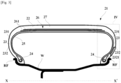
- a tire 21 intended to be mounted on a mounting rim W and comprising a summit 22 surrounded on both sides by side portions 23 terminating in beads 24 provided to cooperate with the mounting rim W.
- the tire 21 comprising at least one carcass reinforcement 25 extending in the summit 22 and the side portions 23 and anchored at its two ends in the beads 24.
- the mounting rim W terminates on both axial sides by a rim flange RF.
- the tire 21 has one carcass reinforcement 25.
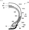
- each the side portion 23 comprising an upper side portion 231 defined as a portion of the side portion 23 outside of the radially outermost carcass reinforcement 25 delimited by a virtual line passing through the upper side point 233 and by a virtual line passing through the intermediate side point 234, and a bottom side portion 232 defined as a portion of the side portion 23 outside of the radially outermost carcass reinforcement 25 delimited by a virtual line passing through the bottom side point 235 and the virtual line passing through the intermediate side point 234.
- a weight of the bottom side portion 232 on one side portion 23 is at least 15% lighter than a weight of the bottom side portion 232 on another side portion 23, thanks to a lightweight bottom side portion 2321, and an outline of the tire 21 between two side portions 23 is symmetric.
- Similar effect may be able to achieve by adding a weight to one side of the bottom side portion 232 at least partially instead of using lightweight bottom side portion 2321, but in view of energy and raw material consumption it is preferable to lighten the weight of one side of the bottom side portion 232 thanks to the lightweight bottom side portion 2321.
- the Example 1 was a tire as described in the above the first embodiment provided with one side of the bottom side portion 25.4% lighter than another side of the bottom side portion considering an area delimited by the virtual line VM and the virtual line VB1.
- the Example 2 was a tire similar to the Example 1 provided with one side of the bottom side portion 32.3% lighter than another side of the bottom side portion considering an area equivalent to that of the Example 1.
- the Reference was a tire provided with equivalent weight on two bottom side portions. The weight of the upper side portions of each the Examples and the Reference were equivalent between the two side portions considering an area delimited by the virtual line VU1 and the virtual line VM. All the Examples and Reference were in the same tire size 235/45R18, and had the same internal construction as standard radial pneumatic tire using the same material.
- Unused test tires were mounted onto all four wheels of a 2,500cc rear-wheel drive hybrid vehicle. On a straight path weather asphalt, the vehicle was coasting down from 105 kph to 50 kph with engine cut off. An interior noise was measured using a microphone positioned at a passenger's ear close to window. An average A-weighted sound pressure level between 50 and 500 Hz from 85 kph to 75 kph was calculated.
- results are shown in table 1.
- results are represented by difference in dB(A) against the Reference, lower the value indicates better the performance.
- a cornering power of unused test tires mounted onto a standard rim and inflated to nominal internal pressure were measured using a flat belt tire tester.
- a load of 460kg was applied while tires driven at a constant speed of 80 kph, lateral force at a slip angle of ⁇ 1° was measured, and the lateral forces measured at +1° and at -1° were averaged.
- Example 1 Example 2 Reference Noise performance (dB(A)) -0.9 -1.5 - Handling performance (index) 100 100 100
Landscapes
- Engineering & Computer Science (AREA)
- Mechanical Engineering (AREA)
- Tires In General (AREA)
Claims (4)
- Reifen (1), der auf einer Montagefelge (W) montiert werden soll, wobei der Reifen (1) eine Krone (2) umfasst, die auf beiden Seiten von Seitenteilen (3) umgeben ist, die in Wulsten (4) enden, die bereitgestellt sind zum Zusammenwirken mit der Montagefelge (W), wobei der Reifen (1) zumindest eine Karkassenverstärkung (5) umfasst, die sich in die Krone (2) und die Seitenteile (3) erstreckt und an ihren beiden Enden in den Wulsten (4) verankert ist, wobei die zumindest eine Karkassenverstärkung (5) an der Außenseite radial von einer Kronenverstärkung (6) aus mehreren Verstärkungslagen (61) überlagert wird, wobei die Kronenverstärkung (6) an der Außenseite radial von einer Lauffläche (7) überlagert wird, die beim Rollen mit dem Boden in Berührung kommen soll,wobei, wenn der Reifen (1) auf seiner Standardmontagefelge montiert und mit dem Nenndruck aufgepumpt wird, jeder Seitenteil (3) drei Punkte aufweist;einen oberen Seitenpunkt (33), definiert als ein Punkt auf einer radial äußersten Karkassenverstärkung (5), an dem sich eine virtuelle Linie senkrecht zur Karkassenverstärkung (5), die sich von einem Punkt auf einer Umrisslinie des Reifens (1) erstreckt, mit einer virtuellen horizontalen Linie, die sich vom axialen Ende einer breitesten Verstärkungslage (61) erstreckt, schneidet;einen unteren Seitenpunkt (35), definiert als ein Punkt auf einer radial äußersten Karkassenverstärkung (5), an dem sich eine virtuelle Linie senkrecht zur Karkassenverstärkung (5), die sich von einem Punkt auf einer Umrisslinie des Reifens (1) erstreckt, mit einer virtuellen horizontalen Linie, die den radial äußersten Rand eines Felgenflansches (RF) berührt, schneidet;einen Zwischenseitenpunkt (34), definiert als ein Punkt auf der radial äußersten Karkassenverstärkung (5), wobei eine Länge vom unteren Seitenpunkt (35) entlang der Karkassenverstärkung (5) 60 % einer Länge zwischen dem oberen Seitenpunkt (33) und dem unteren Seitenpunkt (35) entlang der Karkassenverstärkung (5) beträgt,wobei jeder Seitenteil (3) Folgendes umfasst:einen oberen Seitenteil (31), definiert als ein Teil des Seitenteils (3) außerhalb der radial äußersten Karkassenverstärkung (5), der durch eine virtuelle Linie durch den oberen Seitenteil (33) und durch eine virtuelle Linie durch den Zwischenseitenpunkt (34) begrenzt wird;einen unteren Seitenteil (32), definiert als ein Teil des Seitenteils (3) außerhalb der radial äußersten Karkassenverstärkung (5), der durch eine virtuelle Linie durch den unteren Seitenteil (35) und durch die virtuelle Linie durch den Zwischenseitenpunkt (34) begrenzt wird,wobei ein Gewicht des unteren Seitenteils (32) an einem Seitenteil (3) mindestens 15 % geringer ist als das Gewicht des unteren Seitenteils (32) an einem anderen Seitenteil (3),wobei der Reifen dadurch gekennzeichnet ist, dass der Reifen (1) eine vorgesehene Montageseite (innen-außen) aufweist und dass der leichtere untere Seitenteil (32) innerhalb der vorgesehenen Montageseite sitzt und dass ein Gewicht des oberen Seitenteils (31) ohne den leichteren unteren Seitenteil (32) leichter ist als ein Gewicht des oberen Seitenteils (31), der mit dem leichteren unteren Seitenteil (32) versehen ist.
- Reifen (1) nach Anspruch 1, wobei das Gewicht des unteren Seitenteils (32) an einem Seitenteil (3) höchstens 50 % leichter ist als das Gewicht des unteren Seitenteils (32) an einem anderen Seitenteil (3).
- Reifen (1) nach Anspruch 1 oder Anspruch 2, wobei ein Umriss des Reifens (1) zwischen zwei Seitenteilen (3) asymmetrisch ist.
- Reifen (1) nach Anspruch 1 oder Anspruch 2, wobei ein Umriss des Reifens (1) zwischen zwei Seitenteilen (3) symmetrisch ist.
Applications Claiming Priority (1)
| Application Number | Priority Date | Filing Date | Title |
|---|---|---|---|
| PCT/JP2020/025613 WO2022003804A1 (en) | 2020-06-30 | 2020-06-30 | A mass asymmetric tire |
Publications (2)
| Publication Number | Publication Date |
|---|---|
| EP4171969A1 EP4171969A1 (de) | 2023-05-03 |
| EP4171969B1 true EP4171969B1 (de) | 2024-12-04 |
Family
ID=71670333
Family Applications (1)
| Application Number | Title | Priority Date | Filing Date |
|---|---|---|---|
| EP20742948.1A Active EP4171969B1 (de) | 2020-06-30 | 2020-06-30 | Masseasymmetrischer reifen |
Country Status (6)
| Country | Link |
|---|---|
| US (1) | US12077020B2 (de) |
| EP (1) | EP4171969B1 (de) |
| JP (1) | JP7604526B2 (de) |
| KR (1) | KR102723199B1 (de) |
| CN (1) | CN115803205B (de) |
| WO (1) | WO2022003804A1 (de) |
Family Cites Families (27)
| Publication number | Priority date | Publication date | Assignee | Title |
|---|---|---|---|---|
| US3339610A (en) * | 1965-04-14 | 1967-09-05 | Pirelli | Pneumatic tires having asymmetrical structure |
| JPS52126805A (en) * | 1976-04-16 | 1977-10-25 | Bridgestone Corp | Automotive safetypneumatic tre |
| JPH04201604A (ja) | 1990-11-29 | 1992-07-22 | Minoru Kakizoe | 自動車用タイヤ及び、それに使用するホィール |
| JP2599473Y2 (ja) * | 1993-06-25 | 1999-09-06 | 株式会社ブリヂストン | 空気入りタイヤ |
| CA2143133A1 (en) * | 1994-10-17 | 1996-04-18 | Michael Joseph Weber | Tire and vehicle system utilizing asymmetric support member molded to outer sidewall |
| US5735979A (en) * | 1995-07-24 | 1998-04-07 | Dunlop Tire Corporation | Pneumatic tire with asymmetric tread profile |
| US6267166B1 (en) * | 1999-05-19 | 2001-07-31 | Dunlop Tire Corporation | Radial tire with asymmetric construction |
| JP3631427B2 (ja) * | 2000-09-28 | 2005-03-23 | 住友ゴム工業株式会社 | 重荷重用ラジアルタイヤとリムとの組立体 |
| FR2827810A1 (fr) * | 2001-07-25 | 2003-01-31 | Michelin Soc Tech | Pneumatique ayant des flancs dissymetriques et renforces |
| JP3992538B2 (ja) * | 2002-05-20 | 2007-10-17 | 東洋ゴム工業株式会社 | 空気入りタイヤ及びリム装着タイヤ |
| JP4361318B2 (ja) * | 2003-06-03 | 2009-11-11 | 東洋ゴム工業株式会社 | 乗用車用空気入りタイヤとホイールとの組立体 |
| DE102005044354A1 (de) | 2005-09-16 | 2006-03-30 | Schwarz, Günter | Pannless Fahrzeugreifen SBZ |
| JP2007168544A (ja) * | 2005-12-20 | 2007-07-05 | Yokohama Rubber Co Ltd:The | 空気入りタイヤ |
| JP4568681B2 (ja) * | 2005-12-21 | 2010-10-27 | 株式会社ブリヂストン | 空気入りタイヤ |
| JP5061606B2 (ja) * | 2006-12-08 | 2012-10-31 | 横浜ゴム株式会社 | 空気入りラジアルタイヤ |
| JP2008155866A (ja) * | 2006-12-26 | 2008-07-10 | Bridgestone Corp | 空気入りタイヤ及び空気入りタイヤ付き車両 |
| JP2008279796A (ja) * | 2007-05-08 | 2008-11-20 | Bridgestone Corp | 空気入りタイヤ |
| WO2009057781A1 (ja) * | 2007-11-02 | 2009-05-07 | Bridgestone Corporation | 空気入りラジアルタイヤ |
| KR101087369B1 (ko) * | 2009-10-27 | 2011-11-25 | 금호타이어 주식회사 | 직선 형상의 사이드부를 갖는 공기입 타이어 |
| FR2967612B1 (fr) * | 2010-11-18 | 2012-12-28 | Michelin Soc Tech | Pneumatique a bourrelets dissymetriques. |
| KR20120055301A (ko) * | 2010-11-23 | 2012-05-31 | 한국타이어 주식회사 | 캠버각을 고려한 고속 주행용 비대칭 타이어의 설계방법 |
| JP2012171433A (ja) * | 2011-02-18 | 2012-09-10 | Bridgestone Corp | 空気入りタイヤ |
| JP5803360B2 (ja) | 2011-07-11 | 2015-11-04 | 横浜ゴム株式会社 | インホイールモータ用タイヤ・ホイール組み立て体およびそれに用いるインホイールモータ用の乗用車用空気入りタイヤ |
| FR2978083B1 (fr) | 2011-07-22 | 2013-10-04 | Michelin Soc Tech | Pneumatique allege |
| FR2999983B1 (fr) * | 2012-12-20 | 2015-03-20 | Michelin & Cie | Pneumatique a sommet dissymetrique |
| KR101560484B1 (ko) * | 2014-06-12 | 2015-10-14 | 금호타이어 주식회사 | 조정 안정성이 향상된 비대칭 공기입 타이어 |
| EP3643536B1 (de) * | 2018-10-22 | 2025-06-04 | Sumitomo Rubber Industries, Ltd. | Schwerlastluftreifen |
-
2020
- 2020-06-30 WO PCT/JP2020/025613 patent/WO2022003804A1/en not_active Ceased
- 2020-06-30 CN CN202080102667.6A patent/CN115803205B/zh active Active
- 2020-06-30 JP JP2022580444A patent/JP7604526B2/ja active Active
- 2020-06-30 KR KR1020227045871A patent/KR102723199B1/ko active Active
- 2020-06-30 EP EP20742948.1A patent/EP4171969B1/de active Active
- 2020-06-30 US US18/013,111 patent/US12077020B2/en active Active
Also Published As
| Publication number | Publication date |
|---|---|
| EP4171969A1 (de) | 2023-05-03 |
| US20230278368A1 (en) | 2023-09-07 |
| KR102723199B1 (ko) | 2024-10-30 |
| US12077020B2 (en) | 2024-09-03 |
| CN115803205A (zh) | 2023-03-14 |
| JP7604526B2 (ja) | 2024-12-23 |
| CN115803205B (zh) | 2025-04-29 |
| KR20230027088A (ko) | 2023-02-27 |
| JP2023534399A (ja) | 2023-08-09 |
| WO2022003804A1 (en) | 2022-01-06 |
Similar Documents
| Publication | Publication Date | Title |
|---|---|---|
| EP0678404B1 (de) | Reifen mit reduziertem Wulstgewicht | |
| EP1867497B1 (de) | Run-flat-reifen | |
| EP0844110B1 (de) | Luftreifen | |
| EP2206612B1 (de) | Reifen für kraftrad | |
| US9895939B2 (en) | Run-flat tire and method for mounting the same on four-wheeled vehicle | |
| CN103764410A (zh) | 乘用车用充气子午线轮胎、该轮胎的使用方法以及包括该轮胎的轮胎-轮辋组件 | |
| HK1008737B (en) | Tire with reduced bead mass | |
| US6779573B2 (en) | Pneumatic tires | |
| US4884610A (en) | Depressed radial tire | |
| WO2013065318A1 (ja) | 乗用車用空気入りラジアルタイヤ | |
| US20170355230A1 (en) | Pneumatic Tire | |
| CN103391853B (zh) | 充气子午线轮胎 | |
| US7093633B2 (en) | Self-supporting pneumatic tire | |
| US20210094362A1 (en) | Tire and rim assembly | |
| CN103373176A (zh) | 充气轮胎 | |
| CN112739557B (zh) | 具有减轻重量胎圈区域的轮胎 | |
| EP4171969B1 (de) | Masseasymmetrischer reifen | |
| US7472735B2 (en) | Pneumatic tire | |
| JP2016203780A (ja) | 空気入りタイヤ | |
| US6164353A (en) | Pneumatic tire for passenger cars having shoulder recess | |
| US12420592B2 (en) | Pneumatic radial tire for passenger vehicles | |
| US12434510B2 (en) | Pneumatic radial tire for passenger vehicles | |
| EP4005826B1 (de) | Radialreifen | |
| JP2874827B2 (ja) | 空気入りタイヤ |
Legal Events
| Date | Code | Title | Description |
|---|---|---|---|
| STAA | Information on the status of an ep patent application or granted ep patent |
Free format text: STATUS: UNKNOWN |
|
| STAA | Information on the status of an ep patent application or granted ep patent |
Free format text: STATUS: THE INTERNATIONAL PUBLICATION HAS BEEN MADE |
|
| PUAI | Public reference made under article 153(3) epc to a published international application that has entered the european phase |
Free format text: ORIGINAL CODE: 0009012 |
|
| STAA | Information on the status of an ep patent application or granted ep patent |
Free format text: STATUS: REQUEST FOR EXAMINATION WAS MADE |
|
| 17P | Request for examination filed |
Effective date: 20230130 |
|
| AK | Designated contracting states |
Kind code of ref document: A1 Designated state(s): AL AT BE BG CH CY CZ DE DK EE ES FI FR GB GR HR HU IE IS IT LI LT LU LV MC MK MT NL NO PL PT RO RS SE SI SK SM TR |
|
| DAV | Request for validation of the european patent (deleted) | ||
| DAX | Request for extension of the european patent (deleted) | ||
| GRAP | Despatch of communication of intention to grant a patent |
Free format text: ORIGINAL CODE: EPIDOSNIGR1 |
|
| STAA | Information on the status of an ep patent application or granted ep patent |
Free format text: STATUS: GRANT OF PATENT IS INTENDED |
|
| RIC1 | Information provided on ipc code assigned before grant |
Ipc: B60C 13/00 20060101ALI20240813BHEP Ipc: B60C 3/06 20060101AFI20240813BHEP |
|
| INTG | Intention to grant announced |
Effective date: 20240827 |
|
| GRAS | Grant fee paid |
Free format text: ORIGINAL CODE: EPIDOSNIGR3 |
|
| GRAA | (expected) grant |
Free format text: ORIGINAL CODE: 0009210 |
|
| STAA | Information on the status of an ep patent application or granted ep patent |
Free format text: STATUS: THE PATENT HAS BEEN GRANTED |
|
| AK | Designated contracting states |
Kind code of ref document: B1 Designated state(s): AL AT BE BG CH CY CZ DE DK EE ES FI FR GB GR HR HU IE IS IT LI LT LU LV MC MK MT NL NO PL PT RO RS SE SI SK SM TR |
|
| REG | Reference to a national code |
Ref country code: CH Ref legal event code: EP |
|
| REG | Reference to a national code |
Ref country code: DE Ref legal event code: R096 Ref document number: 602020042496 Country of ref document: DE |
|
| REG | Reference to a national code |
Ref country code: IE Ref legal event code: FG4D |
|
| REG | Reference to a national code |
Ref country code: LT Ref legal event code: MG9D |
|
| REG | Reference to a national code |
Ref country code: NL Ref legal event code: MP Effective date: 20241204 |
|
| PG25 | Lapsed in a contracting state [announced via postgrant information from national office to epo] |
Ref country code: HR Free format text: LAPSE BECAUSE OF FAILURE TO SUBMIT A TRANSLATION OF THE DESCRIPTION OR TO PAY THE FEE WITHIN THE PRESCRIBED TIME-LIMIT Effective date: 20241204 |
|
| PG25 | Lapsed in a contracting state [announced via postgrant information from national office to epo] |
Ref country code: FI Free format text: LAPSE BECAUSE OF FAILURE TO SUBMIT A TRANSLATION OF THE DESCRIPTION OR TO PAY THE FEE WITHIN THE PRESCRIBED TIME-LIMIT Effective date: 20241204 |
|
| PG25 | Lapsed in a contracting state [announced via postgrant information from national office to epo] |
Ref country code: BG Free format text: LAPSE BECAUSE OF FAILURE TO SUBMIT A TRANSLATION OF THE DESCRIPTION OR TO PAY THE FEE WITHIN THE PRESCRIBED TIME-LIMIT Effective date: 20241204 |
|
| PG25 | Lapsed in a contracting state [announced via postgrant information from national office to epo] |
Ref country code: ES Free format text: LAPSE BECAUSE OF FAILURE TO SUBMIT A TRANSLATION OF THE DESCRIPTION OR TO PAY THE FEE WITHIN THE PRESCRIBED TIME-LIMIT Effective date: 20241204 |
|
| PG25 | Lapsed in a contracting state [announced via postgrant information from national office to epo] |
Ref country code: NO Free format text: LAPSE BECAUSE OF FAILURE TO SUBMIT A TRANSLATION OF THE DESCRIPTION OR TO PAY THE FEE WITHIN THE PRESCRIBED TIME-LIMIT Effective date: 20250304 |
|
| PG25 | Lapsed in a contracting state [announced via postgrant information from national office to epo] |
Ref country code: LV Free format text: LAPSE BECAUSE OF FAILURE TO SUBMIT A TRANSLATION OF THE DESCRIPTION OR TO PAY THE FEE WITHIN THE PRESCRIBED TIME-LIMIT Effective date: 20241204 Ref country code: GR Free format text: LAPSE BECAUSE OF FAILURE TO SUBMIT A TRANSLATION OF THE DESCRIPTION OR TO PAY THE FEE WITHIN THE PRESCRIBED TIME-LIMIT Effective date: 20250305 |
|
| PG25 | Lapsed in a contracting state [announced via postgrant information from national office to epo] |
Ref country code: RS Free format text: LAPSE BECAUSE OF FAILURE TO SUBMIT A TRANSLATION OF THE DESCRIPTION OR TO PAY THE FEE WITHIN THE PRESCRIBED TIME-LIMIT Effective date: 20250304 |
|
| PG25 | Lapsed in a contracting state [announced via postgrant information from national office to epo] |
Ref country code: NL Free format text: LAPSE BECAUSE OF FAILURE TO SUBMIT A TRANSLATION OF THE DESCRIPTION OR TO PAY THE FEE WITHIN THE PRESCRIBED TIME-LIMIT Effective date: 20241204 |
|
| REG | Reference to a national code |
Ref country code: AT Ref legal event code: MK05 Ref document number: 1747799 Country of ref document: AT Kind code of ref document: T Effective date: 20241204 |
|
| PG25 | Lapsed in a contracting state [announced via postgrant information from national office to epo] |
Ref country code: SM Free format text: LAPSE BECAUSE OF FAILURE TO SUBMIT A TRANSLATION OF THE DESCRIPTION OR TO PAY THE FEE WITHIN THE PRESCRIBED TIME-LIMIT Effective date: 20241204 |
|
| PG25 | Lapsed in a contracting state [announced via postgrant information from national office to epo] |
Ref country code: PL Free format text: LAPSE BECAUSE OF FAILURE TO SUBMIT A TRANSLATION OF THE DESCRIPTION OR TO PAY THE FEE WITHIN THE PRESCRIBED TIME-LIMIT Effective date: 20241204 |
|
| PGFP | Annual fee paid to national office [announced via postgrant information from national office to epo] |
Ref country code: DE Payment date: 20250618 Year of fee payment: 6 |
|
| PG25 | Lapsed in a contracting state [announced via postgrant information from national office to epo] |
Ref country code: IS Free format text: LAPSE BECAUSE OF FAILURE TO SUBMIT A TRANSLATION OF THE DESCRIPTION OR TO PAY THE FEE WITHIN THE PRESCRIBED TIME-LIMIT Effective date: 20250404 |
|
| PG25 | Lapsed in a contracting state [announced via postgrant information from national office to epo] |
Ref country code: PT Free format text: LAPSE BECAUSE OF FAILURE TO SUBMIT A TRANSLATION OF THE DESCRIPTION OR TO PAY THE FEE WITHIN THE PRESCRIBED TIME-LIMIT Effective date: 20250404 |
|
| PG25 | Lapsed in a contracting state [announced via postgrant information from national office to epo] |
Ref country code: EE Free format text: LAPSE BECAUSE OF FAILURE TO SUBMIT A TRANSLATION OF THE DESCRIPTION OR TO PAY THE FEE WITHIN THE PRESCRIBED TIME-LIMIT Effective date: 20241204 |
|
| PGFP | Annual fee paid to national office [announced via postgrant information from national office to epo] |
Ref country code: FR Payment date: 20250627 Year of fee payment: 6 |
|
| PG25 | Lapsed in a contracting state [announced via postgrant information from national office to epo] |
Ref country code: RO Free format text: LAPSE BECAUSE OF FAILURE TO SUBMIT A TRANSLATION OF THE DESCRIPTION OR TO PAY THE FEE WITHIN THE PRESCRIBED TIME-LIMIT Effective date: 20241204 Ref country code: AT Free format text: LAPSE BECAUSE OF FAILURE TO SUBMIT A TRANSLATION OF THE DESCRIPTION OR TO PAY THE FEE WITHIN THE PRESCRIBED TIME-LIMIT Effective date: 20241204 |
|
| PG25 | Lapsed in a contracting state [announced via postgrant information from national office to epo] |
Ref country code: SK Free format text: LAPSE BECAUSE OF FAILURE TO SUBMIT A TRANSLATION OF THE DESCRIPTION OR TO PAY THE FEE WITHIN THE PRESCRIBED TIME-LIMIT Effective date: 20241204 |
|
| PG25 | Lapsed in a contracting state [announced via postgrant information from national office to epo] |
Ref country code: CZ Free format text: LAPSE BECAUSE OF FAILURE TO SUBMIT A TRANSLATION OF THE DESCRIPTION OR TO PAY THE FEE WITHIN THE PRESCRIBED TIME-LIMIT Effective date: 20241204 |
|
| PG25 | Lapsed in a contracting state [announced via postgrant information from national office to epo] |
Ref country code: IT Free format text: LAPSE BECAUSE OF FAILURE TO SUBMIT A TRANSLATION OF THE DESCRIPTION OR TO PAY THE FEE WITHIN THE PRESCRIBED TIME-LIMIT Effective date: 20241204 |
|
| REG | Reference to a national code |
Ref country code: DE Ref legal event code: R097 Ref document number: 602020042496 Country of ref document: DE |
|
| PG25 | Lapsed in a contracting state [announced via postgrant information from national office to epo] |
Ref country code: SE Free format text: LAPSE BECAUSE OF FAILURE TO SUBMIT A TRANSLATION OF THE DESCRIPTION OR TO PAY THE FEE WITHIN THE PRESCRIBED TIME-LIMIT Effective date: 20241204 |
|
| PG25 | Lapsed in a contracting state [announced via postgrant information from national office to epo] |
Ref country code: DK Free format text: LAPSE BECAUSE OF FAILURE TO SUBMIT A TRANSLATION OF THE DESCRIPTION OR TO PAY THE FEE WITHIN THE PRESCRIBED TIME-LIMIT Effective date: 20241204 |
|
| PLBE | No opposition filed within time limit |
Free format text: ORIGINAL CODE: 0009261 |
|
| STAA | Information on the status of an ep patent application or granted ep patent |
Free format text: STATUS: NO OPPOSITION FILED WITHIN TIME LIMIT |
|
| REG | Reference to a national code |
Ref country code: CH Ref legal event code: L10 Free format text: ST27 STATUS EVENT CODE: U-0-0-L10-L00 (AS PROVIDED BY THE NATIONAL OFFICE) Effective date: 20251015 |
|
| 26N | No opposition filed |
Effective date: 20250905 |
|
| REG | Reference to a national code |
Ref country code: CH Ref legal event code: H13 Free format text: ST27 STATUS EVENT CODE: U-0-0-H10-H13 (AS PROVIDED BY THE NATIONAL OFFICE) Effective date: 20260127 |
|
| PG25 | Lapsed in a contracting state [announced via postgrant information from national office to epo] |
Ref country code: MC Free format text: LAPSE BECAUSE OF FAILURE TO SUBMIT A TRANSLATION OF THE DESCRIPTION OR TO PAY THE FEE WITHIN THE PRESCRIBED TIME-LIMIT Effective date: 20241204 |
|
| PG25 | Lapsed in a contracting state [announced via postgrant information from national office to epo] |
Ref country code: LU Free format text: LAPSE BECAUSE OF NON-PAYMENT OF DUE FEES Effective date: 20250630 |
|
| GBPC | Gb: european patent ceased through non-payment of renewal fee |
Effective date: 20250630 |
|
| REG | Reference to a national code |
Ref country code: BE Ref legal event code: MM Effective date: 20250630 |
|
| PG25 | Lapsed in a contracting state [announced via postgrant information from national office to epo] |
Ref country code: GB Free format text: LAPSE BECAUSE OF NON-PAYMENT OF DUE FEES Effective date: 20250630 |
|
| PG25 | Lapsed in a contracting state [announced via postgrant information from national office to epo] |
Ref country code: IE Free format text: LAPSE BECAUSE OF NON-PAYMENT OF DUE FEES Effective date: 20250630 |
|
| PG25 | Lapsed in a contracting state [announced via postgrant information from national office to epo] |
Ref country code: BE Free format text: LAPSE BECAUSE OF NON-PAYMENT OF DUE FEES Effective date: 20250630 |
|
| PG25 | Lapsed in a contracting state [announced via postgrant information from national office to epo] |
Ref country code: CH Free format text: LAPSE BECAUSE OF NON-PAYMENT OF DUE FEES Effective date: 20250630 |