EP4177425B1 - Externes öffnungssteuergerät für eine kraftfahrzeugöffnung - Google Patents
Externes öffnungssteuergerät für eine kraftfahrzeugöffnung Download PDFInfo
- Publication number
- EP4177425B1 EP4177425B1 EP22185389.8A EP22185389A EP4177425B1 EP 4177425 B1 EP4177425 B1 EP 4177425B1 EP 22185389 A EP22185389 A EP 22185389A EP 4177425 B1 EP4177425 B1 EP 4177425B1
- Authority
- EP
- European Patent Office
- Prior art keywords
- handle
- opening
- support
- lock
- lever
- Prior art date
- Legal status (The legal status is an assumption and is not a legal conclusion. Google has not performed a legal analysis and makes no representation as to the accuracy of the status listed.)
- Active
Links
Images


Classifications
-
- E—FIXED CONSTRUCTIONS
- E05—LOCKS; KEYS; WINDOW OR DOOR FITTINGS; SAFES
- E05B—LOCKS; ACCESSORIES THEREFOR; HANDCUFFS
- E05B81/00—Power-actuated vehicle locks
- E05B81/54—Electrical circuits
- E05B81/90—Manual override in case of power failure
-
- E—FIXED CONSTRUCTIONS
- E05—LOCKS; KEYS; WINDOW OR DOOR FITTINGS; SAFES
- E05B—LOCKS; ACCESSORIES THEREFOR; HANDCUFFS
- E05B85/00—Details of vehicle locks not provided for in groups E05B77/00 - E05B83/00
- E05B85/10—Handles
- E05B85/14—Handles pivoted about an axis parallel to the wing
- E05B85/16—Handles pivoted about an axis parallel to the wing a longitudinal grip part being pivoted at one end about an axis perpendicular to the longitudinal axis of the grip part
-
- E—FIXED CONSTRUCTIONS
- E05—LOCKS; KEYS; WINDOW OR DOOR FITTINGS; SAFES
- E05B—LOCKS; ACCESSORIES THEREFOR; HANDCUFFS
- E05B17/00—Accessories in connection with locks
- E05B17/0004—Lock assembling or manufacturing
-
- E—FIXED CONSTRUCTIONS
- E05—LOCKS; KEYS; WINDOW OR DOOR FITTINGS; SAFES
- E05B—LOCKS; ACCESSORIES THEREFOR; HANDCUFFS
- E05B17/00—Accessories in connection with locks
- E05B17/0012—Accessories in connection with locks for lock parts held in place before or during mounting on the wing
-
- E—FIXED CONSTRUCTIONS
- E05—LOCKS; KEYS; WINDOW OR DOOR FITTINGS; SAFES
- E05B—LOCKS; ACCESSORIES THEREFOR; HANDCUFFS
- E05B17/00—Accessories in connection with locks
- E05B17/0054—Fraction or shear lines; Slip-clutches, resilient parts or the like for preventing damage when forced or slammed
- E05B17/0058—Fraction or shear lines; Slip-clutches, resilient parts or the like for preventing damage when forced or slammed with non-destructive disengagement
-
- E—FIXED CONSTRUCTIONS
- E05—LOCKS; KEYS; WINDOW OR DOOR FITTINGS; SAFES
- E05B—LOCKS; ACCESSORIES THEREFOR; HANDCUFFS
- E05B79/00—Mounting or connecting vehicle locks or parts thereof
- E05B79/02—Mounting of vehicle locks or parts thereof
- E05B79/06—Mounting of handles, e.g. to the wing or to the lock
-
- E—FIXED CONSTRUCTIONS
- E05—LOCKS; KEYS; WINDOW OR DOOR FITTINGS; SAFES
- E05B—LOCKS; ACCESSORIES THEREFOR; HANDCUFFS
- E05B79/00—Mounting or connecting vehicle locks or parts thereof
- E05B79/10—Connections between movable lock parts
- E05B79/20—Connections between movable lock parts using flexible connections, e.g. Bowden cables
-
- E—FIXED CONSTRUCTIONS
- E05—LOCKS; KEYS; WINDOW OR DOOR FITTINGS; SAFES
- E05B—LOCKS; ACCESSORIES THEREFOR; HANDCUFFS
- E05B81/00—Power-actuated vehicle locks
- E05B81/02—Power-actuated vehicle locks characterised by the type of actuators used
- E05B81/04—Electrical
-
- E—FIXED CONSTRUCTIONS
- E05—LOCKS; KEYS; WINDOW OR DOOR FITTINGS; SAFES
- E05B—LOCKS; ACCESSORIES THEREFOR; HANDCUFFS
- E05B81/00—Power-actuated vehicle locks
- E05B81/54—Electrical circuits
- E05B81/64—Monitoring or sensing, e.g. by using switches or sensors
- E05B81/76—Detection of handle operation; Detection of a user approaching a handle; Electrical switching actions performed by door handles
-
- E—FIXED CONSTRUCTIONS
- E05—LOCKS; KEYS; WINDOW OR DOOR FITTINGS; SAFES
- E05B—LOCKS; ACCESSORIES THEREFOR; HANDCUFFS
- E05B85/00—Details of vehicle locks not provided for in groups E05B77/00 - E05B83/00
- E05B85/10—Handles
- E05B85/103—Handles creating a completely closed wing surface
Definitions
- the present invention relates to a device for controlling the exterior opening of a motor vehicle opening.
- the invention relates more particularly but not exclusively to such a control device which combines an electric actuator and a mechanical actuator, capable of triggering the opening of a lock on the door of the motor vehicle.
- this invention relates to a device for controlling the exterior opening of a side opening of the vehicle, both very practical in use and presenting an exterior appearance opening new perspectives for improving the style of motor vehicles, particularly the side style.
- control device comprises an operating pallet (or gripping handle) which is mounted articulated relative to a body panel of the opening, inside a housing.
- This box is generally housed inside a cutout provided for this purpose in the body panel.
- a current trend consists of allowing the opening of the sash by means of an electric actuator, itself triggered manually for example by light pressure, a simple touch or detection of the close presence of a user in a predefined area of the control device, generally a non-visible interior face of the maneuvering pallet.
- an electrical unlocking command to open the vehicle door is generated to the main control unit of the vehicle.
- the opening control device allows mechanical opening in the event of a failure. electric.
- the opening of the mechanical actuator is for example carried out by application to the operating pallet of a significantly higher actuation force, then resulting in the mechanical release of the opening by actuation of a transmission assembly, for example a rod connected to the lock.
- Such a control device is known in particular from the prior art, and in particular from the publication of the international application WO2021/009294A1 .
- Such an opening control device design allows particularly intuitive operation thereof because the motorist who wishes to open the opening of the vehicle proceeds in the same pulling movement, first of all to an attempt to electrically unlock the lock mechanism associated with the pallet by manually triggering the electric actuator located in an interior gripping area of the pallet, then, only in the event of failure to open the sash by exerting a traction force of intensity higher on the handle. It then causes, without changing its movement, the opening of the door by exerting on the pallet a pulling force oriented upwards, which leads to the pivoting of the pallet and the mechanical actuation of the lock.
- the present invention aims to further improve external opening control devices of the type considered.
- the invention aims in particular to propose an opening control device more ergonomic exterior, simpler to assemble while offering new perspectives in the style of the vehicle.
- the subject of the invention is an external opening control device according to the main claim.
- the assembly of the device is simplified thanks to the articulation of the handle on the body of the housing in an arrangement perpendicular to the longitudinal direction of the handle of the device.
- this makes it easier to arrange the lock actuation mechanism while being more ergonomic when the handle is operated.
- This arrangement also makes it possible to offer a new style of motor vehicle opening, allowing relatively discreet integration of the handle into its immediate environment without resorting to complex means.
- the handle is provided with a mechanical actuation branch of the lock extending transversely and configured to act on a transmission assembly linked to the lock.
- the device comprises a manual control element arranged on the interior face of the handle by means of which an electrical control for the electrical actuation of the lock can be generated in such a way that a user can proceed in a single gripping movement of the handle to the electrical actuation of the lock and, in the event of failure, to the mechanical actuation of the lock by application of a pulling force from the handle towards the open position.
- the device comprises a shell shaped to cover the recess, the handle and the shell being configured to cooperate together so that the shell cannot be extracted from the support after assembly of the handle on the support.
- the cavity of the support is configured to impose on the shell an intermediate assembly and/or disassembly position passing through a final location of the handle in the cavity of the support.
- the cavity and the shell are shaped to prevent the shell from being placed in a transverse nesting direction inside the cavity directly in a final destination position of the shell.
- the support comprises a location for transversely receiving a dummy barrel part provided with a front presentation face, the handle being configured in the support to cover the presentation face in the rest position.
- the barrel part comprises a means of attachment to a side wall of the support.
- the device comprises a mechanism for resisting the opening of the gripping handle from its rest position to its open position which presents a hard point crossing separating at least a first part of the opening trajectory of the handle with intense tensile effort of a second part of the trajectory with low tensile effort.
- the opening resistance mechanism comprises a locking lever movably mounted in the support of a configuration for blocking the movement of the handle at a configuration for releasing the movement of the handle, the resistance mechanism comprising means for elastic return of the blocking lever towards the blocking configuration.
- the locking lever comprises a cam profile and the handle comprises an actuation branch configured to act on a transmission assembly of the lock provided at the end with a follower finger cooperating with the along the cam profile when applying a tensile force to the handle.
- the cam profile has a ramp provided with at least one inflection point defining the two trajectory parts.
- the lever forms a return lever configured to pull a traction cable of the lock, when moving towards its release configuration.
- the support comprises a housing for receiving and guiding the elastic means and the lever is mounted to slide in the longitudinal direction of the housing.
- the support includes a passage path which extends from the exterior to the lever in which a handle mounting tool can be engaged to temporarily move the lever to the against the means in order to allow the release of the movement of the handle towards a mounting position.
- the handle extends flush with the panel of the opening and has an exterior surface which defines continuity of shape and/or appearance with a surface of the panel of the opening.
- the operating handle is preferably made flush with the bodywork skin of the opening panel.
- the opening panel receiving the control device is then provided with a cavity open towards the outside to allow the user to slide their hand behind the handle, in order to grasp the internal gripping surface constituting the gripping zone of the handle.
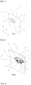
- An orthonormal reference mark is indicated on the figure 1 . It defines a first direction which corresponds to a longitudinal axis Z of the vehicle.
- control device 20 is intended to be mounted on an exterior body panel 14 of the opening 12 which is for example a side door of the motor vehicle 10.
- the panel 14 comprises a visible exterior face 18E and a hidden interior face 18I .
- the device 20 comprises a handle support 26 intended to be mounted in a cutout 16 of complementary shape formed in the exterior panel 14 of the opening 12 and a gripping handle 22 pivotally mounted on the support 26.
- the motor vehicle 10 also includes an opening lock (not shown) typically mounted on the opening 12 of the opening. vehicle 10 and configured to be actuated mechanically and/or electrically.
- an opening lock typically mounted on the opening 12 of the opening. vehicle 10 and configured to be actuated mechanically and/or electrically.
- the handle 22 is intended for operating the opening 14 as well as for the mechanical actuation of opening the lock of the motor vehicle 10.
- the lock is connected to the operating handle 22 by a mechanical connection (also referred to as a transmission assembly) which will be explained in detail later and which allows the mechanical actuation of the opening.
- the opening of an opening of a motor vehicle is carried out for example by means of a lock comprising a bolt (not shown) secured to the opening capable of cooperating with a striker (not shown) secured to the bodywork. of the vehicle.
- a lock comprising a bolt (not shown) secured to the opening capable of cooperating with a striker (not shown) secured to the bodywork. of the vehicle.
- the action of releasing the bolt is called opening the lock, which allows the sash to be released.
- closing the lock is the act of holding the bolt in the strike plate, which prevents the sash from being released.
- the function of the lock is to maintain the opening 12 of the motor vehicle 10 in the closed position.
- the lock also makes it possible to unhook the opening 12 by action on the exterior opening control device 20 which is connected to the lock and operable by a user.
- the bolt is released from the striker by electrical or mechanical actuation of the exterior opening control 20.
- the lock can be opened electrically by means of an electromechanical actuator (not shown in the figures).
- the actuator (not shown) comprises for example an electric motor, electrically powered by the main electrical circuit of the vehicle. This electric motor is sized to allow the lock and sash to open under normal operating conditions.
- the lock is also preferably connected to an electronic central unit (not shown in the figures) for controlling the locking and unlocking of the various locks fitted to the motor vehicle 10.
- the device 20 further comprises a barrel part 30 having a front presentation face 30A.
- the barrel part 30 has in the example illustrated on the Figure 3 a general cylindrical shape with a front presentation face which is preferably relatively flat.
- the lock can be unlocked mechanically.
- the barrel part 30 of the device 20 is functional and is configured to allow the insertion of a lock key through its presentation face 30A.
- the device 20 comprises a lock cover 32 in the form of a cover intended to be mounted removable (articulated in rotation or not) above the location of the barrel part 30 and can be removed manually in order to free access to the presentation face 30A to allow insertion of the lock key.
- the barrel part 30 is preferably a dummy part and is inoperative.
- the handle 22 is configured to cover the location of the barrel part 30 in its rest position.
- the support 26 is formed by a housing body 40 which is intended to be fixed on the internal side 18I of the panel 14 and the gripping handle 22 is intended to be arranged on the external side 18E of the panel 14, while being attached to the housing body 40 forming a support.
- the gripping handle 22 is in the form of a body of generally elongated shape which extends in the longitudinal direction X.
- the handle 22 is in the form of an elongated bar, in the longitudinal direction the opposite side will be referred to as forward side 22A.
- This orientation from back to front corresponds substantially to an orientation from right to left on the figure 1 .
- the handle 22 is mounted articulated on the support 26 by the rear end side 22B around a hinge axis extending in the vertical direction Z relative to the housing body 40.
- the hinge axis will be described as vertical, that is to say substantially parallel to the plane of the exterior panel 14 and perpendicular to the longitudinal direction X of the gripping handle 22.
- the gripping handle 22 is mounted articulated around the geometric axis of articulation relative to the support 26 between at least one extreme retracted rest position and an extreme deployed opening position causing the mechanical actuation of the opening of the lock of the opening 12 causing the opening of the opening 12.
- its rear side 22B has a forked end 34 intended to be mounted for rotation around a pivot rod of the support 26 (not visible in the figures).
- the handle 22 is mechanically linked to the lock mechanism. This allows, thanks to the operation of the handle 22, the mechanical actuation of the opening of the lock and the release of the opening 14.
- the handle 22 comprises, on its front side 22A, a transverse extension actuation branch 36 configured to act on a transmission assembly coupled to the lock mechanism which makes it possible to carry out the mechanical opening of the lock of the opening 12.
- the transmission assembly comprises for example a traction cable and a return lever 62 which will be described in more detail below.
- the housing body 40 has frontally an open front face 42 on the outside of the opening 12 in the general shape of a frame and a rear wall 44 which is arranged to extend from the internal side of the panel 14 of the opening 12
- the housing body 40 includes again in this example a peripheral wall 46 which delimits with the rear wall 44 a cavity 48 for receiving the handle 22 open towards the outside of the opening 12.
- the cavity 48 of the housing body 40 is arranged in the panel 14 of the opening 12 to extend back relative to the exterior surface of the panel 14 and thus receive the gripping handle 22 substantially flush with the exterior surface of panel 14 (or vehicle body skin).
- the handle 22 has an exterior surface which defines surface continuity with a surface of the panel 14 of the opening 12 and possibly also appearance continuity.
- the handle 22 is arranged in the body of the housing 40 to partially close the internal cavity 48 of the housing body 40 in the rest position so that in the example illustrated, a lower longitudinal edge of the handle 22 defines vertically downwards a concave clearance 50 in the shape of, for example, a bucket or half-bowl allowing the insertion of a user's hand behind the handle 22.
- the cavity 48 open towards the outside is partially closed by the handle 22 so as to make an interior face of the handle 22 accessible for gripping through the clearance 50.
- the internal face of the user's phalanges faces the internal face of the handle 22.
- the handle 22 can be arranged so as to close a lower portion of the internal cavity 48 such that an upper longitudinal edge of the handle 22 delimits vertically in this case upwards the concave clearance. It is also possible that the handle 22 can be arranged so as to close a middle portion of the internal cavity 48 such that the handle 22 vertically delimits both upwards and downwards concave clearances.
- the device 20 further comprises a covering shell 52 configured to fit the clearance 50 of the open cavity 48 of the housing 40 not closed by the handle 22 in its position of rest.
- the shell 52 forms a finishing trim making it possible to cover the part of the recess 48 of the housing body 40 not covered by the handle 22 in its rest position.
- the housing 40 is functionally composed of at least two parts: a first upper part for receiving the handle 22 in the rest position and a second lower part for access to gripping the handle 22 in its rest position.
- This second part comprises the concave recess 48 open to the outside which forms the access clearance 50 to the internal face of the handle 22 in its retracted rest position.
- the housing body 40 comprises in the longitudinal direction at one end of its first part a location in which is provided a bore 54 shaped to transversely accommodate the barrel part 30 such that the barrel 30 presents frontally its presentation side 30A.
- the front end part 22A of the handle 22 is shaped to cover the presentation face 30A in the rest position of the handle 22.
- the front end portion 22A of the handle 22 forms a front longitudinal extension of the handle 22 beyond a position of the actuating branch 36 of the handle 22.
- the visual delimitation of the first and second parts of the housing body 40 is marked by a vertical step 56 forming a shoulder and visible on the Figure 9 .
- the housing body 40 has a generally oblong contour and is provided with a lobe-shaped projection in which the location for the cylindrical bore 54 for receiving the barrel part 30 is located.
- the barrel part 30 comprises a means of attachment 78 to a side wall of the support 26.
- the device 10 also comprises a manual control element 100 arranged on an interior gripping face of the handle 22 by means of which an electrical command for the electrical opening of the lock of the opening 12 can be generated.
- the manual control element 100 may for example comprise, by way of example but not limitation, a gesture and/or touch detector configured to detect at least one control instruction linked to a result of the gesture and/or detection. tactile in a control region preferably located on the interior face of the handle 22.
- the detector comprises, for example, a sensor using pressure-sensitive resistor technology (also known as the FSR sensor for “Force Sensing Resistor” according to Anglo-Saxon terminology), using, for example, pressure-sensitive resistive inks, a optical technology or even capacitive technology.
- pressure-sensitive resistor technology also known as the FSR sensor for “Force Sensing Resistor” according to Anglo-Saxon terminology
- this manual control actuated by a simple tactile touch, a very light pressure or detection of the presence of the user, the latter can proceed in a single gripping movement of the handle 22 to the electrical unlocking of the lock of the opening and, only in the event of failure, to mechanical unlocking of the opening lock by applying a pulling force from the handle towards the open position.
- the handle 22 In normal operation of the device 20, the handle 22 is intended to mainly occupy its retracted rest position and to be operated only occasionally.
- the device 20 further comprises a mechanism 60 for resisting the opening of the handle 22 from its rest position to its opening position.
- the mechanism 60 comprises for example a hard point crossing which separates at least a first part opening trajectory of the handle 22 with intense tensile effort of a second part of trajectory with low tensile effort.
- the opening resistance mechanism 60 comprises a locking lever 62 movably mounted in the housing body 40 from a locking configuration of the handle 22 in the retracted position to a release configuration of the handle 22 towards its deployed position.
- the resistance mechanism 60 preferably comprises elastic return means 64 of the lever 62 towards the blocking configuration.
- the locking lever 62 comprises a cam profile 66 and the actuation branch 36 of the handle 22 is provided at the end with a follower finger 38 cooperating along the cam profile 66 ( Figure 6 ) when applying a tensile force to the handle 22 towards its open position (the movement of the follower finger 38 and the lever 62 is shown in broken lines).
- the cam profile 66 has a ramp provided with at least one inflection point P separating the first part of the trajectory with relatively higher tensile effort and a second part of the trajectory with relatively lower tensile effort.
- the locking lever 62 comprises mechanical connection means to a mechanical transmission element of the lock, such as a cable.
- the locking lever 62 is part of the mechanical transmission assembly and is configured to pull the traction cable of the lock, as it moves towards its release configuration.
- moving the handle 22 towards its deployed opening position has the effect of moving the lever 62 and thus causing traction on the cable causing the lock to release.
- the support 26 further comprises a housing 80 for receiving and guiding the elastic return means 64 and the locking lever 62 which is mounted movable in sliding in the longitudinal direction of the housing 80.
- the housing 80 is presented in this example in the form of a frame, generally rectangular and extending in length according to the direction longitudinal of the support 26 on the rear wall 44.
- the actuation branch 36 of the handle 22 extends transversely inside the support 26 passing through the rear wall 44 of the housing 40 so that the end of the actuating branch 36 cooperates with the resistance mechanism 60 of the handle 22 located at the rear of the housing 40 ( figure 2 ).
- the follower finger 38 extends inside the housing 80 in the vertical direction Z and is positioned in contact with the ramp portion 66 of the lever 62.
- the lever 62 is in this example guided in movement according to the main direction of the housing 80 in sliding.
- the support 26 comprises a passage path 82 which extends from the outside to the locking lever 62 in which a temporary assembly tool 84 can be engaged which can for example be a screw 76 ( Figure 15 ) or a specifically shaped mounting part such as that shown on the Figure 16 .
- a temporary assembly tool 84 can be engaged which can for example be a screw 76 ( Figure 15 ) or a specifically shaped mounting part such as that shown on the Figure 16 .
- the tool 84 When the tool 84 is inserted in the passage path 82, for example formed by a through orifice 82 of a wall of the frame of the housing 80, it can temporarily move the locking lever 62 against the elastic return means 64 in order to allow the installation of the handle 22 in its final mounting destination position inside the housing 40.
- the device 20 can be delivered pre-assembled with the mounting screw 76 in the screwed state, that is to say engaging the locking lever 62 in the release configuration of the handle 22 easily allowing the installation of the handle 22 in its resting mounting position ( Figure 17 , position A).
- the mounting screw 76 can be unscrewed in order to release the locking lever 62 and allow its elastic return in the locking configuration of the handle 22 thanks to the elastic means 64.
- the elastic return member 64 comprises in this example a spring operating in compression.
- the lever 62 comprises a main body in the form of a stud provided with a bearing face with the spring 64.
- the lever 62 also includes a cable traction arm which is formed in the extension of the main body.
- the arm comprises a cable retaining end in the form of a pin 63 and the support 26 also comprises a cable guide element 27.
- the lever 62 preferably comprises, opposite the bearing face of the spring, a protuberance longitudinal extension delimiting the ramp profile.
- the bearing face of the lever 62 also includes, in the example illustrated, a pin 68 for centering the spring 64.
- the device 20 according to the invention also differs from the prior art by a simplicity of design allowing simple and robust assembly without the need for multiple parts.
- the housing body 40 forming the support 26 is attached by rapid coupling means 70 to the panel 14 of the opening 12.
- the panel 14 of the opening 12 has at the periphery of its cutout 16 a plurality of snap-fit or interlocking projections 72 and the housing body 40 comprises a plurality of complementary cavities 74 arranged at the peripheral edge of the front face of the housing 40.
- the projections 72 and the complementary cavities 74 form in this example the quick coupling means 70.
- Other quick coupling means can be envisaged without departing from the scope of the invention.
- These means of rapid coupling of the two parts advantageously allow the two parts to be relatively positioned between them before fixing them with each other by conventional fixing means 75. This allows easy, rapid and precise positioning of the support 26 when its mounting on the opening panel 14.
- the housing body 40 is secured to the panel 14 by conventional fixing means 75 such as screws and fixing holes.
- the opening 12 has laterally an orifice 79 configured to allow access to the fixing of the screws 76 and 78 ( figure 2 And 15 ).
- This orifice 79 is for example accessible through a side wall 15 of the opening 12 when opening the opening 12.
- the hubcap shell 52 and the support 26 are preferably shaped to fit into one another as is illustrated in the Figure 14 .
- the shell 52 is shaped to cover the recess 50, the handle 22 and the shell 52 being configured to cooperate together so that the shell 52 cannot be extracted from the support 26 after assembly or installation of the handle 22 on the support 26 in its final mounting destination position.
- the cavity 48 of the support 26 is configured to impose on the shell 52 an intermediate assembly and/or disassembly position passing through a final location of the handle 22 in the cavity 48 of the support 26.
- the shell 52 reaches an intermediate mounting position passing through the first part of the body of the housing 40 intended to receive the handle 22. Consequently, once the handle 22 positioned in the cavity 48, the shell 52 cannot be removed without crossing the location reception of the handle 22 which is then made impassable by the handle 22.
- the cavity 48 and the shell 52 are shaped to prevent the shell 52 from being placed in a transverse nesting direction inside the cavity 48 directly in a final destination position of the shell 52.
- the intermediate mounting position (shown in dotted lines) is a vertically higher position relative to the final destination position of the shell 52 in the support 26 (mode A) or is an inclined position relative to the final destination position of the shell 52 (mode B) or a combination of these two positions intermediaries.
- Such an exterior opening control device 20 reduces the number of parts to be supplied, handled and assembled.
Landscapes
- Engineering & Computer Science (AREA)
- Manufacturing & Machinery (AREA)
- Lock And Its Accessories (AREA)
Claims (15)
- [Vorrichtung (20) zur Steuerung der Außenöffnung einer Tür (12) eines Kraftfahrzeugs (10), mit einem Träger (26), der dazu bestimmt ist, in einem Ausschnitt (16) einer Platte (14) der Tür (12) montiert zu werden, einen Griff (22) zum Greifen, der in Bezug auf den Träger (26) zwischen mindestens einer eingezogenen Ruhestellung und einer ausgefahrenen Öffnungsstellung zur mechanischen Betätigung eines Schlosses des Türflügels (12) gelenkig montiert ist und bei dem der Träger (26) einen Gehäusekörper (40) hat, der einen nach außen offenen Hohlraum (48) begrenzt, den der Griff (22) in der Ruhestellung teilweise verschließt, indem er eine konkave Aussparung (50) für den Zugang zum Greifen einer Innenseite des Griffs (22) hinterlässt, dadurch gekennzeichnet, dass der Griff (22) einen Körper mit einer allgemein länglichen Form in einer Längsrichtung umfasst, der einen Gelenkendabschnitt (22B) an dem Träger (26) um eine Gelenkachse aufweist, die im Wesentlichen parallel zu der Ebene der Platte (14) des Flügels (12) und im Wesentlichen senkrecht zur Längsrichtung des Griffs (22) verläuft, und dass der Griff (22) bündig mit der Platte (14) des Flügels (12) verläuft und eine Außenfläche aufweist, die eine Kontinuität der Form und/oder des Aussehens mit einer Oberfläche der Platte (14) des Flügels (12) definiert.
- Vorrichtung (20) nach dem vorhergehenden Anspruch, bei der der Griff (22) mit einem sich quer erstreckenden Schenkel (36) zur mechanischen Betätigung des Schlosses versehen ist, der so konfiguriert ist, dass er auf eine mit dem Schloss verbundene Übertragungsanordnung einwirkt.
- Vorrichtung (20) nach einem der vorhergehenden Ansprüche, mit einem an der Innenseite des Griffs (22) angeordneten Handbedienelement (100), mittels dessen ein elektrischer Befehl zur elektrischen Betätigung des Schlosses erzeugbar ist, so dass ein Benutzer in einer einzigen Greifbewegung des Griffs (22) die elektrische Betätigung des Schlosses und, falls diese nicht erfolgreich ist, die mechanische Betätigung des Schlosses durch Aufbringen einer Zugkraft auf den Griff (22) in Richtung der Öffnungsposition vornehmen kann.
- Vorrichtung (20) nach einem der vorhergehenden Ansprüche, mit einer Schale (52), die so geformt ist, dass sie die Aussparung (50) verkleidet, wobei der Griff (22) und die Schale (52) so gestaltet sind, dass sie zusammenwirken, so dass die Schale (52) nach dem Zusammenbau des Griffs (22) mit dem Träger (26) nicht aus dem Träger (26) herausgezogen werden kann.
- Vorrichtung (20) nach dem vorhergehenden Anspruch, wobei der Hohlraum (48) der Halterung (26) so konfiguriert ist, dass er der Schale (52) eine Zwischenposition für die Montage und/oder Demontage aufzwingt, die durch eine endgültige Position des Griffs (22) in dem Hohlraum (48) der Halterung (26) verläuft.
- Vorrichtung (20) nach einem der Ansprüche 4 bis 5, wobei der Hohlraum (48) und die Schale (52) so geformt sind, dass sie das Einsetzen der Schale (52) in einer quer verlaufenden Schachtelungsrichtung innerhalb des Hohlraums (48) direkt in einer endgültigen Zielposition der Schale (52) verhindern.
- Vorrichtung (20) nach einem der vorhergehenden Ansprüche, wobei die Halterung (26) eine Stelle zur Queraufnahme einer Zylinderattrappe (30) umfasst, die mit einer vorderen Präsentationsfläche (30A) versehen ist, wobei der Griff (22) in der Halterung (26) so konfiguriert ist, dass er in der Ruheposition die Präsentationsfläche (30A) abdeckt.
- Vorrichtung (20) nach dem vorhergehenden Anspruch, wobei das Trommelstück (30) ein Mittel (78) zur Befestigung an einer Seitenwand des Trägers (26) umfasst.
- Vorrichtung (20) nach einem der vorhergehenden Ansprüche, mit einem Mechanismus (60) zum Widerstand gegen das Öffnen des Greifgriffs (22) aus seiner Ruheposition in seine Öffnungsposition, der eine Überwindung eines harten Punkts aufweist, der mindestens einen ersten Teil der Öffnungsbahn des Griffs (22) mit intensiver Zugkraft von einem zweiten Teil der Bahn mit geringer Zugkraft trennt.
- Vorrichtung (20) nach dem vorhergehenden Anspruch, bei der der Öffnungswiderstandsmechanismus (60) einen Sperrhebel (62) umfasst, der in der Halterung (26) von einer Konfiguration zum Sperren der Bewegung des Griffs (22) zu einer Konfiguration zum Freigeben der Bewegung des Griffs (22) beweglich montiert ist, wobei der Widerstandsmechanismus (60) Mittel (64) zum elastischen Zurückstellen des Sperrhebels (62) in die Sperrkonfiguration umfasst.
- Vorrichtung (20) nach dem vorhergehenden Anspruch, bei der der Sperrhebel (62) ein Nockenprofil (66) umfasst und der Griff (22) einen Betätigungsschenkel (36) umfasst, der so konfiguriert ist, dass er auf eine Übertragungsanordnung des Schlosses einwirkt, die am Ende mit einem Folgefinger (38) versehen ist, der entlang des Nockenprofils (66) zusammenwirkt, wenn eine Zugkraft auf den Griff (22) ausgeübt wird.
- Vorrichtung (20) nach dem vorhergehenden Anspruch, bei der das Nockenprofil (66) eine Rampe aufweist, die mit mindestens einem Wendepunkt (P) versehen ist, der die beiden Teile der Flugbahnen definiert.
- Vorrichtung (20) nach einem der Ansprüche 10 bis 12, wobei der Hebel (62) einen Umlenkhebel bildet, der so konfiguriert ist, dass er ein Zugseil des Schlosses nachzieht, wenn es in seine Freigabekonfiguration bewegt wird.
- Vorrichtung (20) nach einem der Ansprüche 10 bis 13, bei der der Träger (26) eine Aufnahme (80) zur Aufnahme und Führung der elastischen Mittel (64) aufweist und der Hebel (62) in Längsrichtung der Aufnahme (80) gleitend beweglich angebracht ist.
- Vorrichtung (20) nach einem der Ansprüche 10 bis 14, wobei der Träger (26) einen Durchgangspfad (82) aufweist, der sich von außen zum Hebel (62) erstreckt, in den ein Werkzeug (84) zur Montage des Griffs (22) eingreifen kann, um den Hebel (62) vorübergehend gegen die Mittel (64) zu bewegen, um die Freigabe der Bewegung des Griffs (22) in eine Montageposition zu ermöglichen.
Applications Claiming Priority (1)
| Application Number | Priority Date | Filing Date | Title |
|---|---|---|---|
| FR2107932A FR3125552B1 (fr) | 2021-07-22 | 2021-07-22 | Dispositif de commande d’ouverture extérieure d’un ouvrant de véhicule automobile. |
Publications (3)
| Publication Number | Publication Date |
|---|---|
| EP4177425A1 EP4177425A1 (de) | 2023-05-10 |
| EP4177425C0 EP4177425C0 (de) | 2024-03-27 |
| EP4177425B1 true EP4177425B1 (de) | 2024-03-27 |
Family
ID=77317166
Family Applications (1)
| Application Number | Title | Priority Date | Filing Date |
|---|---|---|---|
| EP22185389.8A Active EP4177425B1 (de) | 2021-07-22 | 2022-07-18 | Externes öffnungssteuergerät für eine kraftfahrzeugöffnung |
Country Status (4)
| Country | Link |
|---|---|
| US (1) | US20230049181A1 (de) |
| EP (1) | EP4177425B1 (de) |
| CN (1) | CN115680393A (de) |
| FR (1) | FR3125552B1 (de) |
Families Citing this family (2)
| Publication number | Priority date | Publication date | Assignee | Title |
|---|---|---|---|---|
| EP3835519B1 (de) * | 2019-12-09 | 2022-05-18 | U-Shin Italia S.p.A. | Motorisierter türrahmengriff für ein kraftfahrzeug |
| US12523079B2 (en) * | 2021-11-18 | 2026-01-13 | Motherson Innovations Company Limited | Electrical charging flap |
Family Cites Families (12)
| Publication number | Priority date | Publication date | Assignee | Title |
|---|---|---|---|---|
| DE19845395C2 (de) * | 1998-10-02 | 2001-05-10 | Daimler Chrysler Ag | Griffanordnung für eine Fahrzeugtür |
| DE10151870B4 (de) * | 2001-10-24 | 2005-06-16 | Huf Hülsbeck & Fürst Gmbh & Co. Kg | Vorrichtung zur Betätigung eines Verschlusses von Türen oder Klappen, insbesondere an Fahrzeugen |
| DE20210610U1 (de) * | 2002-07-08 | 2002-10-02 | Arau GmbH, 73614 Schorndorf | Innenbetätigungsvorrichtung für Türen von Kraftfahrzeugen |
| JP5064440B2 (ja) * | 2009-05-21 | 2012-10-31 | 株式会社ホンダロック | 車両用ドアのアウトハンドル装置 |
| DE102009045874A1 (de) * | 2009-10-20 | 2011-04-21 | Huf Hülsbeck & Fürst Gmbh & Co. Kg | Griffvorrichtung mit Schalenlager |
| JP5727744B2 (ja) * | 2010-09-30 | 2015-06-03 | 株式会社アルファ | 車両のドアインサイドハンドル装置 |
| US9593514B2 (en) * | 2013-02-18 | 2017-03-14 | Ford Global Technologies, Llc | Seamless exterior handle for a vehicle door |
| EP3179020B1 (de) * | 2015-12-07 | 2019-04-24 | Huf Hülsbeck & Fürst GmbH & Co. KG | Türgriffanordnung eines kraftfahrzeugs |
| EP3712362B1 (de) * | 2019-03-21 | 2022-08-17 | U-Shin Italia S.p.A. | Türgriffanordnung mit einem äusseren rahmenmechanismus und einem inneren haltermechanismus |
| US12146347B2 (en) * | 2019-04-18 | 2024-11-19 | Volvo Car Corporation | Low-profile handle assembly |
| DE102019119529A1 (de) | 2019-07-18 | 2021-01-21 | Volkswagen Aktiengesellschaft | Türöffnungseinrichtung und Türöffnungssystem für ein Kraftfahrzeug |
| DE102019135304A1 (de) * | 2019-12-19 | 2021-06-24 | Huf Hülsbeck & Fürst Gmbh & Co. Kg | Kraftfahrzeug-Türgriffanordnung |
-
2021
- 2021-07-22 FR FR2107932A patent/FR3125552B1/fr active Active
-
2022
- 2022-07-18 EP EP22185389.8A patent/EP4177425B1/de active Active
- 2022-07-22 CN CN202210867651.5A patent/CN115680393A/zh active Pending
- 2022-07-22 US US17/871,313 patent/US20230049181A1/en not_active Abandoned
Also Published As
| Publication number | Publication date |
|---|---|
| CN115680393A (zh) | 2023-02-03 |
| EP4177425C0 (de) | 2024-03-27 |
| US20230049181A1 (en) | 2023-02-16 |
| FR3125552B1 (fr) | 2025-05-02 |
| EP4177425A1 (de) | 2023-05-10 |
| FR3125552A1 (fr) | 2023-01-27 |
Similar Documents
| Publication | Publication Date | Title |
|---|---|---|
| FR2948402A1 (fr) | Commande d'ouverture exterieure d'un ouvrant de vehicule automobile et ouvrant equipe d'une telle commande d'ouverture | |
| EP3581741A1 (de) | Mechanische notfall-entriegelung öffnungskontrolle | |
| FR2623779A1 (fr) | Dispositif d'ouverture/fermeture | |
| EP4056794B1 (de) | Verbesserte steuerung der innenöffnung | |
| FR2800784A1 (fr) | Dispositif de commande d'un mecanisme de verrouillage d'une porte d'un vehicule | |
| FR3110623A1 (fr) | Dispositif d’accès de secours d’ouvrant de véhicule à bras de déploiement rotatif | |
| EP3879051A1 (de) | Externe öffnungskontrolle der kraftfahrzeugtür | |
| EP4177425A1 (de) | Externes öffnungssteuergerät für eine kraftfahrzeugöffnung | |
| EP4206430A1 (de) | Externes öffnungssteuervorrichtung zum öffnen eines kraftfahrzeugsflügels | |
| FR2958962A1 (fr) | Commande d'ouverture interieure d'un ouvrant de vehicule automobile et vehicule automobile equipee d'une telle commande. | |
| EP3722544A1 (de) | Griffsystem mit sicherheitsvorrichtung | |
| EP1738043B1 (de) | Schlüssel mit einklappbarem schaft mit mitteln zum bewegen des schafts in eine ausgeklappte position | |
| EP3775452B1 (de) | Vorrichtung zum öffnen einer öffnungsplatte und mit solch einer vorrichtung ausgestattetes fahrzeug | |
| WO2012042065A1 (fr) | Poignée d'ouvrant de véhicule comprenant deux leviers | |
| EP0816604B1 (de) | Betätigungsvorrichtung zum Öffnen einer Fahrzeugtür | |
| EP0003267A1 (de) | Zurückhalte- und Schliessvorrichtung für Ersatzradhalter | |
| EP0748916B1 (de) | Betätigungsvorrichtung für ein Tor oder andere Verschlussplatte | |
| EP2750938A1 (de) | Diebstahlsicherung für eine lenksäule und zugehörige lenksäule | |
| EP0906997A1 (de) | Verriegelungsvorrichtung mit einem nockenbetätigten Übertragungselement | |
| FR2963944A1 (fr) | Ensemble comprenant une commande d'ouverture interieure d'un ouvrant de vehicule automobile et des elements d'actionnement permettant de deverrouiller une serrure et d'ouvrir ledit ouvrant | |
| FR2767854A1 (fr) | Serrure de portes d'enceintes industrielles | |
| FR2814190A1 (fr) | Mecanisme de manoeuvre de porte | |
| EP1637676B1 (de) | Türgriff und Verfahren zur Montage desgleichen | |
| EP2704926B1 (de) | Diebstahlschutzvorrichtung für lenksäule und entsprechende lenksäule | |
| EP4283079A1 (de) | Vorrichtung zur vereinfachten öffnungssteuerung |
Legal Events
| Date | Code | Title | Description |
|---|---|---|---|
| PUAI | Public reference made under article 153(3) epc to a published international application that has entered the european phase |
Free format text: ORIGINAL CODE: 0009012 |
|
| STAA | Information on the status of an ep patent application or granted ep patent |
Free format text: STATUS: THE APPLICATION HAS BEEN PUBLISHED |
|
| AK | Designated contracting states |
Kind code of ref document: A1 Designated state(s): AL AT BE BG CH CY CZ DE DK EE ES FI FR GB GR HR HU IE IS IT LI LT LU LV MC MK MT NL NO PL PT RO RS SE SI SK SM TR |
|
| STAA | Information on the status of an ep patent application or granted ep patent |
Free format text: STATUS: REQUEST FOR EXAMINATION WAS MADE |
|
| 17P | Request for examination filed |
Effective date: 20231016 |
|
| RBV | Designated contracting states (corrected) |
Designated state(s): AL AT BE BG CH CY CZ DE DK EE ES FI FR GB GR HR HU IE IS IT LI LT LU LV MC MK MT NL NO PL PT RO RS SE SI SK SM TR |
|
| GRAP | Despatch of communication of intention to grant a patent |
Free format text: ORIGINAL CODE: EPIDOSNIGR1 |
|
| STAA | Information on the status of an ep patent application or granted ep patent |
Free format text: STATUS: GRANT OF PATENT IS INTENDED |
|
| INTG | Intention to grant announced |
Effective date: 20231212 |
|
| GRAS | Grant fee paid |
Free format text: ORIGINAL CODE: EPIDOSNIGR3 |
|
| GRAA | (expected) grant |
Free format text: ORIGINAL CODE: 0009210 |
|
| STAA | Information on the status of an ep patent application or granted ep patent |
Free format text: STATUS: THE PATENT HAS BEEN GRANTED |
|
| AK | Designated contracting states |
Kind code of ref document: B1 Designated state(s): AL AT BE BG CH CY CZ DE DK EE ES FI FR GB GR HR HU IE IS IT LI LT LU LV MC MK MT NL NO PL PT RO RS SE SI SK SM TR |
|
| REG | Reference to a national code |
Ref country code: GB Ref legal event code: FG4D Free format text: NOT ENGLISH |
|
| REG | Reference to a national code |
Ref country code: CH Ref legal event code: EP |
|
| REG | Reference to a national code |
Ref country code: DE Ref legal event code: R096 Ref document number: 602022002547 Country of ref document: DE |
|
| REG | Reference to a national code |
Ref country code: IE Ref legal event code: FG4D Free format text: LANGUAGE OF EP DOCUMENT: FRENCH |
|
| U01 | Request for unitary effect filed |
Effective date: 20240423 |
|
| U07 | Unitary effect registered |
Designated state(s): AT BE BG DE DK EE FI FR IT LT LU LV MT NL PT SE SI Effective date: 20240429 |
|
| PG25 | Lapsed in a contracting state [announced via postgrant information from national office to epo] |
Ref country code: GR Free format text: LAPSE BECAUSE OF FAILURE TO SUBMIT A TRANSLATION OF THE DESCRIPTION OR TO PAY THE FEE WITHIN THE PRESCRIBED TIME-LIMIT Effective date: 20240628 |
|
| PG25 | Lapsed in a contracting state [announced via postgrant information from national office to epo] |
Ref country code: HR Free format text: LAPSE BECAUSE OF FAILURE TO SUBMIT A TRANSLATION OF THE DESCRIPTION OR TO PAY THE FEE WITHIN THE PRESCRIBED TIME-LIMIT Effective date: 20240327 Ref country code: RS Free format text: LAPSE BECAUSE OF FAILURE TO SUBMIT A TRANSLATION OF THE DESCRIPTION OR TO PAY THE FEE WITHIN THE PRESCRIBED TIME-LIMIT Effective date: 20240627 |
|
| PG25 | Lapsed in a contracting state [announced via postgrant information from national office to epo] |
Ref country code: RS Free format text: LAPSE BECAUSE OF FAILURE TO SUBMIT A TRANSLATION OF THE DESCRIPTION OR TO PAY THE FEE WITHIN THE PRESCRIBED TIME-LIMIT Effective date: 20240627 Ref country code: NO Free format text: LAPSE BECAUSE OF FAILURE TO SUBMIT A TRANSLATION OF THE DESCRIPTION OR TO PAY THE FEE WITHIN THE PRESCRIBED TIME-LIMIT Effective date: 20240627 Ref country code: HR Free format text: LAPSE BECAUSE OF FAILURE TO SUBMIT A TRANSLATION OF THE DESCRIPTION OR TO PAY THE FEE WITHIN THE PRESCRIBED TIME-LIMIT Effective date: 20240327 Ref country code: GR Free format text: LAPSE BECAUSE OF FAILURE TO SUBMIT A TRANSLATION OF THE DESCRIPTION OR TO PAY THE FEE WITHIN THE PRESCRIBED TIME-LIMIT Effective date: 20240628 |
|
| U20 | Renewal fee for the european patent with unitary effect paid |
Year of fee payment: 3 Effective date: 20240628 |
|
| PG25 | Lapsed in a contracting state [announced via postgrant information from national office to epo] |
Ref country code: IS Free format text: LAPSE BECAUSE OF FAILURE TO SUBMIT A TRANSLATION OF THE DESCRIPTION OR TO PAY THE FEE WITHIN THE PRESCRIBED TIME-LIMIT Effective date: 20240727 |
|
| PG25 | Lapsed in a contracting state [announced via postgrant information from national office to epo] |
Ref country code: SM Free format text: LAPSE BECAUSE OF FAILURE TO SUBMIT A TRANSLATION OF THE DESCRIPTION OR TO PAY THE FEE WITHIN THE PRESCRIBED TIME-LIMIT Effective date: 20240327 |
|
| PG25 | Lapsed in a contracting state [announced via postgrant information from national office to epo] |
Ref country code: ES Free format text: LAPSE BECAUSE OF FAILURE TO SUBMIT A TRANSLATION OF THE DESCRIPTION OR TO PAY THE FEE WITHIN THE PRESCRIBED TIME-LIMIT Effective date: 20240327 |
|
| PG25 | Lapsed in a contracting state [announced via postgrant information from national office to epo] |
Ref country code: CZ Free format text: LAPSE BECAUSE OF FAILURE TO SUBMIT A TRANSLATION OF THE DESCRIPTION OR TO PAY THE FEE WITHIN THE PRESCRIBED TIME-LIMIT Effective date: 20240327 |
|
| PG25 | Lapsed in a contracting state [announced via postgrant information from national office to epo] |
Ref country code: PL Free format text: LAPSE BECAUSE OF FAILURE TO SUBMIT A TRANSLATION OF THE DESCRIPTION OR TO PAY THE FEE WITHIN THE PRESCRIBED TIME-LIMIT Effective date: 20240327 |
|
| PG25 | Lapsed in a contracting state [announced via postgrant information from national office to epo] |
Ref country code: SK Free format text: LAPSE BECAUSE OF FAILURE TO SUBMIT A TRANSLATION OF THE DESCRIPTION OR TO PAY THE FEE WITHIN THE PRESCRIBED TIME-LIMIT Effective date: 20240327 |
|
| PG25 | Lapsed in a contracting state [announced via postgrant information from national office to epo] |
Ref country code: SM Free format text: LAPSE BECAUSE OF FAILURE TO SUBMIT A TRANSLATION OF THE DESCRIPTION OR TO PAY THE FEE WITHIN THE PRESCRIBED TIME-LIMIT Effective date: 20240327 Ref country code: SK Free format text: LAPSE BECAUSE OF FAILURE TO SUBMIT A TRANSLATION OF THE DESCRIPTION OR TO PAY THE FEE WITHIN THE PRESCRIBED TIME-LIMIT Effective date: 20240327 Ref country code: RO Free format text: LAPSE BECAUSE OF FAILURE TO SUBMIT A TRANSLATION OF THE DESCRIPTION OR TO PAY THE FEE WITHIN THE PRESCRIBED TIME-LIMIT Effective date: 20240327 Ref country code: PL Free format text: LAPSE BECAUSE OF FAILURE TO SUBMIT A TRANSLATION OF THE DESCRIPTION OR TO PAY THE FEE WITHIN THE PRESCRIBED TIME-LIMIT Effective date: 20240327 Ref country code: IS Free format text: LAPSE BECAUSE OF FAILURE TO SUBMIT A TRANSLATION OF THE DESCRIPTION OR TO PAY THE FEE WITHIN THE PRESCRIBED TIME-LIMIT Effective date: 20240727 Ref country code: ES Free format text: LAPSE BECAUSE OF FAILURE TO SUBMIT A TRANSLATION OF THE DESCRIPTION OR TO PAY THE FEE WITHIN THE PRESCRIBED TIME-LIMIT Effective date: 20240327 Ref country code: CZ Free format text: LAPSE BECAUSE OF FAILURE TO SUBMIT A TRANSLATION OF THE DESCRIPTION OR TO PAY THE FEE WITHIN THE PRESCRIBED TIME-LIMIT Effective date: 20240327 |
|
| U1N | Appointed representative for the unitary patent procedure changed after the registration of the unitary effect |
Representative=s name: RENARD, ALEXIS; FR |
|
| REG | Reference to a national code |
Ref country code: DE Ref legal event code: R097 Ref document number: 602022002547 Country of ref document: DE |
|
| PG25 | Lapsed in a contracting state [announced via postgrant information from national office to epo] |
Ref country code: MC Free format text: LAPSE BECAUSE OF FAILURE TO SUBMIT A TRANSLATION OF THE DESCRIPTION OR TO PAY THE FEE WITHIN THE PRESCRIBED TIME-LIMIT Effective date: 20240327 |
|
| PLBE | No opposition filed within time limit |
Free format text: ORIGINAL CODE: 0009261 |
|
| STAA | Information on the status of an ep patent application or granted ep patent |
Free format text: STATUS: NO OPPOSITION FILED WITHIN TIME LIMIT |
|
| 26N | No opposition filed |
Effective date: 20250103 |
|
| PG25 | Lapsed in a contracting state [announced via postgrant information from national office to epo] |
Ref country code: IE Free format text: LAPSE BECAUSE OF NON-PAYMENT OF DUE FEES Effective date: 20240718 |
|
| U20 | Renewal fee for the european patent with unitary effect paid |
Year of fee payment: 4 Effective date: 20250707 |
|
| PG25 | Lapsed in a contracting state [announced via postgrant information from national office to epo] |
Ref country code: CY Free format text: LAPSE BECAUSE OF FAILURE TO SUBMIT A TRANSLATION OF THE DESCRIPTION OR TO PAY THE FEE WITHIN THE PRESCRIBED TIME-LIMIT; INVALID AB INITIO Effective date: 20220718 |
|
| REG | Reference to a national code |
Ref country code: CH Ref legal event code: H13 Free format text: ST27 STATUS EVENT CODE: U-0-0-H10-H13 (AS PROVIDED BY THE NATIONAL OFFICE) Effective date: 20260224 |
|
| PG25 | Lapsed in a contracting state [announced via postgrant information from national office to epo] |
Ref country code: HU Free format text: LAPSE BECAUSE OF FAILURE TO SUBMIT A TRANSLATION OF THE DESCRIPTION OR TO PAY THE FEE WITHIN THE PRESCRIBED TIME-LIMIT; INVALID AB INITIO Effective date: 20220718 |
|
| PG25 | Lapsed in a contracting state [announced via postgrant information from national office to epo] |
Ref country code: CH Free format text: LAPSE BECAUSE OF NON-PAYMENT OF DUE FEES Effective date: 20250731 |