EP4182995B1 - Module de stockage d'énergie permettant de stocker de l'énergie électrique - Google Patents
Module de stockage d'énergie permettant de stocker de l'énergie électrique Download PDFInfo
- Publication number
- EP4182995B1 EP4182995B1 EP20753669.9A EP20753669A EP4182995B1 EP 4182995 B1 EP4182995 B1 EP 4182995B1 EP 20753669 A EP20753669 A EP 20753669A EP 4182995 B1 EP4182995 B1 EP 4182995B1
- Authority
- EP
- European Patent Office
- Prior art keywords
- energy storage
- side wall
- storage module
- adjacent
- storage unit
- Prior art date
- Legal status (The legal status is an assumption and is not a legal conclusion. Google has not performed a legal analysis and makes no representation as to the accuracy of the status listed.)
- Active
Links
Images


Classifications
-
- H—ELECTRICITY
- H01—ELECTRIC ELEMENTS
- H01M—PROCESSES OR MEANS, e.g. BATTERIES, FOR THE DIRECT CONVERSION OF CHEMICAL ENERGY INTO ELECTRICAL ENERGY
- H01M50/00—Constructional details or processes of manufacture of the non-active parts of electrochemical cells other than fuel cells, e.g. hybrid cells
- H01M50/50—Current conducting connections for cells or batteries
- H01M50/502—Interconnectors for connecting terminals of adjacent batteries; Interconnectors for connecting cells outside a battery casing
-
- H—ELECTRICITY
- H01—ELECTRIC ELEMENTS
- H01M—PROCESSES OR MEANS, e.g. BATTERIES, FOR THE DIRECT CONVERSION OF CHEMICAL ENERGY INTO ELECTRICAL ENERGY
- H01M10/00—Secondary cells; Manufacture thereof
- H01M10/04—Construction or manufacture in general
- H01M10/0481—Compression means other than compression means for stacks of electrodes and separators
-
- H—ELECTRICITY
- H01—ELECTRIC ELEMENTS
- H01M—PROCESSES OR MEANS, e.g. BATTERIES, FOR THE DIRECT CONVERSION OF CHEMICAL ENERGY INTO ELECTRICAL ENERGY
- H01M50/00—Constructional details or processes of manufacture of the non-active parts of electrochemical cells other than fuel cells, e.g. hybrid cells
- H01M50/20—Mountings; Secondary casings or frames; Racks, modules or packs; Suspension devices; Shock absorbers; Transport or carrying devices; Holders
- H01M50/204—Racks, modules or packs for multiple batteries or multiple cells
- H01M50/207—Racks, modules or packs for multiple batteries or multiple cells characterised by their shape
- H01M50/213—Racks, modules or packs for multiple batteries or multiple cells characterised by their shape adapted for cells having curved cross-section, e.g. round or elliptic
-
- H—ELECTRICITY
- H01—ELECTRIC ELEMENTS
- H01M—PROCESSES OR MEANS, e.g. BATTERIES, FOR THE DIRECT CONVERSION OF CHEMICAL ENERGY INTO ELECTRICAL ENERGY
- H01M50/00—Constructional details or processes of manufacture of the non-active parts of electrochemical cells other than fuel cells, e.g. hybrid cells
- H01M50/20—Mountings; Secondary casings or frames; Racks, modules or packs; Suspension devices; Shock absorbers; Transport or carrying devices; Holders
- H01M50/262—Mountings; Secondary casings or frames; Racks, modules or packs; Suspension devices; Shock absorbers; Transport or carrying devices; Holders with fastening means, e.g. locks
-
- H—ELECTRICITY
- H01—ELECTRIC ELEMENTS
- H01M—PROCESSES OR MEANS, e.g. BATTERIES, FOR THE DIRECT CONVERSION OF CHEMICAL ENERGY INTO ELECTRICAL ENERGY
- H01M50/00—Constructional details or processes of manufacture of the non-active parts of electrochemical cells other than fuel cells, e.g. hybrid cells
- H01M50/20—Mountings; Secondary casings or frames; Racks, modules or packs; Suspension devices; Shock absorbers; Transport or carrying devices; Holders
- H01M50/271—Lids or covers for the racks or secondary casings
-
- H—ELECTRICITY
- H01—ELECTRIC ELEMENTS
- H01M—PROCESSES OR MEANS, e.g. BATTERIES, FOR THE DIRECT CONVERSION OF CHEMICAL ENERGY INTO ELECTRICAL ENERGY
- H01M50/00—Constructional details or processes of manufacture of the non-active parts of electrochemical cells other than fuel cells, e.g. hybrid cells
- H01M50/50—Current conducting connections for cells or batteries
- H01M50/502—Interconnectors for connecting terminals of adjacent batteries; Interconnectors for connecting cells outside a battery casing
- H01M50/503—Interconnectors for connecting terminals of adjacent batteries; Interconnectors for connecting cells outside a battery casing characterised by the shape of the interconnectors
-
- H—ELECTRICITY
- H01—ELECTRIC ELEMENTS
- H01M—PROCESSES OR MEANS, e.g. BATTERIES, FOR THE DIRECT CONVERSION OF CHEMICAL ENERGY INTO ELECTRICAL ENERGY
- H01M50/00—Constructional details or processes of manufacture of the non-active parts of electrochemical cells other than fuel cells, e.g. hybrid cells
- H01M50/50—Current conducting connections for cells or batteries
- H01M50/502—Interconnectors for connecting terminals of adjacent batteries; Interconnectors for connecting cells outside a battery casing
- H01M50/507—Interconnectors for connecting terminals of adjacent batteries; Interconnectors for connecting cells outside a battery casing comprising an arrangement of two or more busbars within a container structure, e.g. busbar modules
-
- H—ELECTRICITY
- H01—ELECTRIC ELEMENTS
- H01M—PROCESSES OR MEANS, e.g. BATTERIES, FOR THE DIRECT CONVERSION OF CHEMICAL ENERGY INTO ELECTRICAL ENERGY
- H01M50/00—Constructional details or processes of manufacture of the non-active parts of electrochemical cells other than fuel cells, e.g. hybrid cells
- H01M50/50—Current conducting connections for cells or batteries
- H01M50/502—Interconnectors for connecting terminals of adjacent batteries; Interconnectors for connecting cells outside a battery casing
- H01M50/509—Interconnectors for connecting terminals of adjacent batteries; Interconnectors for connecting cells outside a battery casing characterised by the type of connection, e.g. mixed connections
- H01M50/512—Connection only in parallel
-
- H—ELECTRICITY
- H01—ELECTRIC ELEMENTS
- H01M—PROCESSES OR MEANS, e.g. BATTERIES, FOR THE DIRECT CONVERSION OF CHEMICAL ENERGY INTO ELECTRICAL ENERGY
- H01M50/00—Constructional details or processes of manufacture of the non-active parts of electrochemical cells other than fuel cells, e.g. hybrid cells
- H01M50/50—Current conducting connections for cells or batteries
- H01M50/502—Interconnectors for connecting terminals of adjacent batteries; Interconnectors for connecting cells outside a battery casing
- H01M50/514—Methods for interconnecting adjacent batteries or cells
- H01M50/517—Methods for interconnecting adjacent batteries or cells by fixing means, e.g. screws, rivets or bolts
-
- Y—GENERAL TAGGING OF NEW TECHNOLOGICAL DEVELOPMENTS; GENERAL TAGGING OF CROSS-SECTIONAL TECHNOLOGIES SPANNING OVER SEVERAL SECTIONS OF THE IPC; TECHNICAL SUBJECTS COVERED BY FORMER USPC CROSS-REFERENCE ART COLLECTIONS [XRACs] AND DIGESTS
- Y02—TECHNOLOGIES OR APPLICATIONS FOR MITIGATION OR ADAPTATION AGAINST CLIMATE CHANGE
- Y02E—REDUCTION OF GREENHOUSE GAS [GHG] EMISSIONS, RELATED TO ENERGY GENERATION, TRANSMISSION OR DISTRIBUTION
- Y02E60/00—Enabling technologies; Technologies with a potential or indirect contribution to GHG emissions mitigation
- Y02E60/10—Energy storage using batteries
Definitions
- the invention relates to an energy storage module for storing electrical energy, with an energy storage device having a top, a bottom and a substantially rectangular outer circumference, wherein the energy storage device comprises a plurality of energy storage units, each of which has at least two adjacent energy storage cells with poles aligned to the top and bottom of the energy storage device, wherein the positive poles of each of the energy storage units are connected to one another via a first electrically conductive cell connector and the negative poles via a second electrically conductive cell connector, and the first cell connector is electrically connected to a first and the second cell connector to a second connection tab, wherein the connection tabs are arranged on an outside of the energy storage unit facing a first side surface of the rectangular outer circumference of the energy storage device, wherein the first connection tab of the energy storage units is connected via an electrically conductive connecting element to the second connection tab of the energy storage unit adjacent to the first side surface in a longitudinal direction.
- Such an energy storage module is known, for example, from the publication JP 2016-91959 A .
- Other energy storage modules are also known from the WO 2020/071642 , the FR3 077 431 and the US 2015 / 0 180 093 A1 .
- the disadvantage here is that both for the production of the energy storage modules, in particular for the positioning of the energy storage cells, and for the spatial separation of the cells from one another, additional elements are necessary to separate the energy storage cells from one another, which make the modules unnecessarily complex and lead to increased production costs and at the same time have a negative impact on the possible packing density of the energy storage cells.
- the present invention is therefore based on the object of overcoming the disadvantages of the prior art, in particular of improving an energy storage module in such a way that it is particularly easy to manufacture with a particularly compact and material-saving design and has a high level of stability.
- the energy storage module further comprises a housing with a side wall associated with the first side surface, to which the connecting elements are fastened in such a way that they can be fastened to the connecting lugs associated with them.
- the energy storage device Due to its rectangular outer circumference, the energy storage device can extend in a longitudinal dimension along the side surfaces and in a transverse dimension along the end faces.
- the width of an energy storage unit can in particular correspond to twice the diameter of an energy storage cell plus the intended expansion distance.
- the longitudinal dimension can therefore in particular correspond to the width of an energy storage unit multiplied by the number of energy storage units plus the number of expansion distances provided between the energy storage units.
- the intended expansion distances can correspond to the maximum expected radial expansion of two adjacent cells, whereby the expected radial expansion can depend on the expected maximum operating temperature.
- the maximum expected operating temperature can depend on the type of use or the place of use.
- the axes of adjacent energy storage cells can be arranged in such a way that an equilateral triangle is formed between them. This arrangement enables the lowest possible energy storage cell density to be achieved.
- the energy storage unit can have a plurality of energy storage cell pairs offset from one another in a zigzag pattern in its transverse dimension, among other things due to the arrangement in equilateral triangles. This means that the distance between two energy storage cell pairs can be the sum of the energy storage cell diameter plus the intended expansion distance multiplied by the factor ⁇ 3/2.
- the transverse dimension of the energy storage unit can be the number of energy storage cell pairs arranged next to one another in the transverse direction, subtracted by the value 1 multiplied by the above-mentioned distance between two energy storage cell pairs.
- the energy storage cells can be cylindrical and have a non-conductive cylinder shell. The axes of the cylindrical cells can in particular be aligned parallel to one another.
- the energy storage cells can be battery cells or capacitor cells, for example.
- the cells of an energy storage unit can be spaced apart from one another to the intended expansion distance, in particular, by the cell connectors that connect the positive poles on the one hand and the negative poles on the other. The cell connectors thus connect the cells of an energy storage unit in a parallel circuit.
- the cell connectors can, for example, be welded onto the cells. Additional spacers between the cells can therefore be dispensed with.
- the connecting elements serve the purpose of bringing the energy storage units into contact with one another and of keeping immediately adjacent cells of adjacent energy storage units at the intended expansion distance.
- the type of connection according to the invention has the advantage that the lateral connection achieves increased stability of the energy storage device.
- the connecting elements connect the energy storage units to one another in series. It can be provided that the connection tabs are connected in one piece to the cell connectors and are bent over on the sides of the energy storage units onto the outer surfaces of the energy storage cells. The connection tabs can be bent either centrally between the two energy storage cells of the energy storage unit or only onto one of the energy storage cells.
- connection tabs on the top and bottom of the side surface of the energy storage unit can face each other and in particular be spaced apart from each other.
- the connection tabs can in particular be sheet metal sections and have a rectangular or semi-circular shape.
- the connecting element can be a connecting plate or a wire, for example.
- the connecting plate can, for example, be attached to the associated connection tabs with its end sections.
- the energy storage module has a housing with a side wall assigned to the first side surface, to which the connecting elements are fastened in such a way that they can be fastened to the connecting lugs assigned to them, the alignment of the connecting elements to the associated connecting lugs can thus be predetermined by the side wall geometry. It can be provided that contact between the connecting lugs and the connecting elements is achieved by fastening the side wall to the energy storage module.
- the connecting elements can be prestressed relative to the side wall, for example via prestressing elements.
- the side wall can have fixing windows assigned to the connection lugs and aligned with them, via which the connecting elements can be fixed to the connection lugs from the outside of the housing.
- the fixing windows can be openings made in the side wall.
- the fixing windows can correspond to the geometry of the connection lugs.
- the connecting elements can be welded to the connection lugs after the side wall has been assembled.
- the pre-aligned connecting elements mean that no separate adjustment of the connecting elements on the connection lugs is necessary, so that the energy storage module can be manufactured quickly and inexpensively.
- the side wall can have at least one, in particular two, locking elements adjacent to the fixing window for fixing the connecting element associated with the fixing window.
- the locking elements can be provided in particular on the side of the side wall facing the energy storage device.
- the locking elements can in particular have a contact surface and a locking projection.
- the connecting element can have a rectangular shape and on each of the outer sides of the connecting element there can be a locking element with one of the respective
- the connecting element can be anchored to the side wall in particular with a contact surface assigned to the outside. In this way, the connecting element can be anchored to the side wall.
- the adjacent fixing window to which the other end of the connecting element is to be fixed also has two locking elements with contact surfaces that are perpendicular to one another and facing one another or aligned with the contact surfaces of the associated adjacent fixing window.
- the locking projections border on the contact surfaces so that the contact surfaces are undercut behind the locking projections.
- the side wall can then be fixed to the energy storage module together with the assembled connecting elements and the connecting elements can be welded to the associated connection tabs.
- the contact surfaces can have a width that allows connecting elements with a thickness of, for example, 0.8 mm to be accommodated.
- the side wall can also have a plurality of spring elements, in particular a number corresponding to the number of energy storage cells, for generating a preload between the side wall and the energy storage device when the side wall is mounted.
- spring elements can be formed on the side wall, which extend away from the side wall at an angle with their opposite end.
- the clamping webs can, for example, have a spring travel of 2 mm.
- the spring elements can be arranged both near the upper edge and near the lower edge of the side wall.
- the clamping webs on the upper edge can extend in the direction of the upper edge and the clamping webs on the lower edge can extend in the direction of the lower edge.
- the housing can comprise a base and/or a cover, wherein the side wall can have a corner recess extending in the longitudinal direction on its upper and/or lower edge for vertically supporting and laterally fixing the base and/or the cover.
- the cover and the base can be dimensioned such that they have at least the longitudinal dimension and the transverse dimension of the energy storage device and can also rest on the corner recess of the side wall.
- the side wall can also have a plurality of fastening element receptacles pointing towards the upper and/or lower edge, via which the base and/or the lid can be fixed to the associated corner recesses.
- the fastening element receptacles can each have support surfaces which are on the Level of the corner recesses.
- the fastening element receptacles can be formed on the side wall.
- the fastening element receptacles can be screwing points with holes. The screwing points can have countersunk holes.
- a longitudinal free space can be provided between the fastening element receptacles on the upper edge and the fastening element receptacles on the lower edge and between the upper and lower fixing windows.
- a longitudinal groove can be provided in the side wall.
- the groove can be a cable duct, for example.
- the side wall can have at least one opening for cable passage in the area of the groove.
- an opening can be provided between the upper and lower screwing points.
- the side wall can have a stiffening part on its side facing away from the energy storage device, which extends essentially in the longitudinal direction of the side wall and has a plurality of openings aligned with the fixing windows.
- the stiffening part can be made of metal.
- the side wall can have a longitudinal groove on its outside, in which the stiffening part is received.
- the stiffening part can also have a plurality of openings aligned with the openings for cable feedthrough.
- the stiffening part can also have fastening tabs that protrude laterally beyond the side wall in the longitudinal direction for connecting the side wall to the adjacent housing walls.
- the housing can comprise a head part covering the adjacent energy storage unit on at least one of the end faces of the rectangular outer circumference of the energy storage device, which head part has a plurality of fastening element receptacles pointing towards the upper and/or lower edge of the head part, via which the base and/or the cover can be fixed to the head part.
- the fastening element receptacles can correspond to the fastening element receptacles of the side wall.
- the head part can also have a plurality of spring elements for generating a preload between the head part and the energy storage device when the head part is mounted. The spring elements can be designed to match the side wall.
- the head part can be connected to the free connection tab of the adjacent energy storage unit via at least one electrically conductive connection element.
- the electrically conductive connection element can have a first section that extends essentially perpendicularly away from the head part.
- the connection element can also have a second section that is arranged parallel to the head part and via which the connection element is attached to the head part.
- the connection element can, for example, be a electrically conductive sheet metal.
- the second section can be bent from the first section, in particular at a right angle.
- first cell connector can be electrically connected to a third connection tab and the second cell connector to a fourth connection tab, which are arranged on an outside of the energy storage unit facing a second side surface of the rectangular outer circumference opposite the first side surface, wherein the third connection tab of the energy storage units is connected via an electrically conductive connecting element to the fourth connection tab of the energy storage unit adjacent to the first side surface in a longitudinal direction.
- the housing can further comprise a side wall associated with the second side surface, which can comprise the same features as the opposite first side wall.
- the side walls can in particular be identical parts.
- the energy storage module can comprise, for example, seven, ten or thirteen energy storage units, or possibly even more, which are arranged next to one another in the longitudinal direction of the side wall.
- the energy storage module can be expanded to any desired current strength by varying the energy storage cells per energy storage unit, as well as to any voltage by varying the number of energy storage units.
- the at least two energy storage cells of the energy storage units are adjacent in the longitudinal direction of the side wall, wherein the energy storage unit further comprises a plurality of further pairs of energy storage cells each adjacent in the longitudinal direction of the side wall, wherein the plurality of energy storage cell pairs extend in a direction transverse to the side wall.
- all positive and negative poles of the energy storage cells are aligned to the top or bottom of the energy storage unit, so that the connecting elements connect adjacent energy storage units diagonally. Diagonal connections can achieve a particularly high level of stability of the module, as this is the most effective way to prevent the energy storage units from tipping relative to one another.
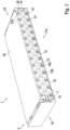
- the energy storage module 1 shown has an energy storage device 3 consisting of 13 energy storage units 7 arranged next to one another in the longitudinal direction, each of which has eleven energy storage cell pairs arranged next to one another in the transverse direction, i.e. each has twenty-two energy storage cells 8.
- the energy storage cells 8 are each cylindrical and their axes are aligned parallel to one another.
- the energy storage cell pairs are arranged next to one another in a zigzag shape, so that the distances between all energy storage cells 8 are dimensioned such that their axes form equilateral triangles with respect to one another.
- a predetermined expansion distance is provided between all energy storage cells 8, which compensates for expansion of the energy storage cells 8 during operation of the energy storage module 1.
- a first cell connector 11a is arranged on each energy storage unit 7, which electrically connects the upwardly facing positive poles 9 of the energy storage cells 8 to one another and at the same time keeps the energy storage cells 8 at their predetermined distance from one another.
- a second cell connector 11b is arranged on each energy storage unit 7, which connects the negative poles of all energy storage cells 8 of the respective energy storage units 7 with each other and also keeps the energy storage cells 8 at their predetermined distance from each other on the underside.
- the energy storage units 7 are arranged relative to one another such that the energy storage 3 has side surfaces 29a, 29b running in the longitudinal direction of the energy storage module 1.
- the cell connectors 11a and 11b each have connection tabs 12a, 12b, 12c, 12d, which are each bent over onto the side surface 29a or side surface 29b, so that the connection tabs 12a and 12b of each energy storage unit 7 each face each other on the side surface 29a and the connection tabs 12c and 12d of each energy storage unit 7 each face each other on the opposite side surface 29b.
- the energy storage module 1 further comprises a housing 2, which comprises side walls 17a and 17b, a front head part 18, a rear head part 19, as well as a base 15 and a cover 16. While the cover 16 covers the top 4 of the energy storage device 1 and the base 15 covers the bottom 5 of the energy storage device 1, the side walls 17a and 17b are arranged along the side surfaces 29a, 29b of the energy storage device 3 and the head parts 18 and 19 are each arranged at the front on the transverse sides 32a, 32b of the energy storage module 1.
- the side walls 17a and 17b each comprise locking elements 25, via which electrical connecting elements 13 are each attached diagonally to the side walls 17a, 17b, facing the energy storage device 3.
- connection tabs 13 are already aligned by placing the side walls on the side surfaces in such a way that they are or can be connected to the corresponding connection tabs twelve A to twelve A. It can be seen that for each connection tab 12a-12d, one or two locking elements 25 are provided, in which an end section of a connecting element 13 is held. It can be seen that from left to right of the energy storage module 1, the connecting elements 13 each connect a lower connection tab 12b or 12d of a first energy storage unit 7 to an upper connection tab 12a or 12c of a second energy storage unit 7 arranged to the right of the first energy storage unit 7.
- the connection tabs that remain free are each connected via connection elements 14 attached to the head parts.
- the connecting elements 13 can be pre-tensioned, for example, via spring elements, so that an electrical connection between the connection tabs 12a-12d and the respective connecting elements 13 is established simply by placing the side walls on the energy storage module 1.
- the side parts 17a and 17b also have stiffening parts 20, which are each arranged in a longitudinal direction of the side walls 17a, 17b extending recesses 26 and increase the flexural rigidity of the side walls 17a, 17b.
- the side walls 17a and 17b also have fixing windows 27, which are each aligned with the connection lugs 12a to 12d or the end sections of the connecting elements 13 attached to the side walls.
- the stiffening parts 20 placed on the side walls 17a, 17b have corresponding openings 21, which are also aligned with the fixing windows 27, so that from the outside of the housing, in the assembled state of the side walls 17a, 17b, a connection of the connecting elements 13 to the respective connection lugs 12a-12d can be produced, for example by welding.
- the base 15 and the cover 16 are connected to the housing outer elements.
- the side walls 17a, 17b and the head parts 18, 19 each have a plurality of regularly spaced fastening element receptacles 23, which are each arranged along the upper edge 30 and the lower edge 31 of the housing outer elements and point in the direction of the cover 16 or base 15.
- the fastening element receptacles 23 are shown as screwing points for countersunk screws, so that the cover 16 and base 15 can be screwed to the outer housing elements.
- a plurality of spring elements 24 are arranged on the outer housing elements, which can be designed as clamping webs as shown.
- the clamping webs can have a spring travel of 2 mm, for example.
- the spring elements 24 serve the purpose of creating a preload between the respective housing wall and the energy storage device in order to achieve a central positioning of the energy storage device 3 in the housing 2 and to protect the energy storage device 3 against impacts.
- FIG. 2 shows the energy storage module 1 in the assembled state, i.e. the energy storage 3, which is accommodated in the housing 2, wherein the side walls 17a and 17b are each connected to the front head part 18 and the rear head part 19 and the cover 16 and the base 15 are each screwed to the outer housing shell.
- connection tabs 12a-12d are connected to the connecting elements 13.
- the connection tab 12a of the energy storage unit 7 adjacent to the front head part 18 is electrically connected to the connection element 14 fastened to the front head part 18.
- the connection tab 12b of the energy storage unit 7 adjacent to the rear head part 19 is electrically connected to the connection element 14 fastened to the rear head part 19.
- the connecting elements 14 are connected centrally to the head elements 18, 19 and are angled parallel to the other connecting elements 13.
- the Connecting elements 13 connect adjacent energy storage units 7 to one another in such a way that the connecting element 13 runs from the lower connection tab 12b of a left energy storage unit 7 to the upper connection tab 12a of a right energy storage unit 7 arranged to the right. It can be seen that the connection points between the connecting elements 13 and the respective connection tabs 12a-12d can be reached from the outside of the housing through the openings 21 in the stiffening part 20 and the fixing windows 27 in the side walls 17A, 17b. This means that after the side walls have been put in place, the connection tabs can be welded to the respective ends of the connecting elements 13.
- the opposite side of the energy storage module 1, not shown, is designed symmetrically to the side shown, so that there the connecting elements 13 connect adjacent energy storage units 7 to one another in such a way that the connecting element 13 runs from the lower connection tab 12d of a left energy storage unit 7 to the upper connection tab 12c of a right energy storage unit 7 arranged to the right.
- FIG. 3 The top view of an energy storage module 1 shown shows in particular the connection of the side elements 17a, 17b to the cover 16 on the top side 4 of the energy storage device 3.
- the connection of the housing outer elements to the base 15 takes place in the same way.
- the side walls 17 A and 17 B and the head parts 18 and 19 have screwing points 23 at regular intervals, via which the cover 16 is screwed to the respective elements.
- the spring elements 24 can also be seen which, when the energy storage module 1 is assembled, generate a preload between the energy storage device 3 accommodated in the housing 2 and the side walls 17a, 17b.
- the side walls 17a and 17b each have two spring elements 24 between two screwing points 23, with the spring elements 24 being arranged to the right and left of the fixing windows 27.
- the head parts 18 and 19 each have a spring element 24 between the screwing points 23.
- FIG 4 shows a detailed section of the side walls 17a, 17b.
- the side walls 17a, 17b and the head parts 18, 19 are each plastic parts produced by injection molding.
- the spring elements 24, the fastening element receptacles 23 and the locking elements 25 are molded onto the side walls 17a1, 17b.
- the fixing windows 27 are each designed as rectangular openings.
- the cable ducts 33 are also designed as rectangular openings. It can be seen that a free space is formed in the middle in the longitudinal direction of the side wall between the fixing windows 27 and the fastening element receptacles 23, which can be used as a cable duct 22, for example, whereby the openings 33 can each serve to feed through cables.
- the Free space also serves to guide the connecting elements 13 diagonally between the fastening element receptacles 23.
- the spring elements 24 are formed on the lower edge 31 as clamping webs which are formed at an acute angle and point downwards and extend up to a distance of 2 mm from the side wall.
- the spring elements 24 are formed symmetrically on the upper edge 30 so as to point upwards.
- two locking elements 25 are provided to the left and right, each of which has a support surface and a locking projection, the support surfaces of both locking elements 25 assigned to a fixing window 27 being at a right angle to one another and pointing towards one another.
- the transverse side of a connecting element 13 can be held on one of the locking elements 25 and the long side of a connecting element 13 can be held on the other locking element 25.
- the opposite transverse side and the other longitudinal side of the same connecting element 13 are held by the locking elements 25 of the diagonally spaced fixing window 27.
- the connecting elements 13 can be clicked into the desired position over the locking projections.
- the side wall 17a, 17b each has a corner recess 28, which serves as a support surface and as a lateral boundary for the cover 16 and base 15.
- the side wall 17a, 17b On its side facing away from the energy storage device 3, the side wall 17a, 17b has a recess 26 in which the stiffening part 20 can be accommodated.
- FIG. 5 and Figure 6 show the head parts of the housing 2, which are also manufactured using the injection molding process and which are not designed as identical parts due to the geometry of the energy storage units 7.
- the energy storage cells 8 of the energy storage units 7 are each lined up in a straight line along the side walls 17a, 17b.
- the energy storage cells 8 have a zigzag shape in the transverse direction of the energy storage module 1.
- the rear head part 19 has two folded edges 35 on the outside, by means of which the outer energy storage cells 8 of the energy storage unit 7 resting on the rear head part 19 can be supported by the spring elements 24 of the head part.
- the head parts 18, 19 also each have fastening element receptacles 23 in the form of screwing points, whereby these protrude further in the transverse direction than the fastening element receptacles 23 of the side walls due to the geometry of the energy storage units 7 described above.
- the spring elements 24 of the head parts 18, 19 also protrude further than those of the side walls 17a, 17b and for this purpose are formed further centrally on the head parts on the one hand and on the other hand have a larger Length than the spring elements 24 of the side walls.
- the front head part also has a plurality of holes 34 for fastening connection elements.
- the embodiment shown has thirteen energy storage units 7 arranged next to one another.
- the energy storage units 7 each have eleven energy storage cell pairs that are adjacent to one another in the transverse direction of the energy storage unit 3 and are offset from one another in a zigzag shape.
- the energy storage cell pairs are each formed from two energy storage cells 8 that are adjacent to one another in the longitudinal direction of the energy storage unit 3. All positive poles 9 of the energy storage cells 8 of the energy storage units 7 face the top side 4 of the energy storage unit 3 and are mechanically and electrically connected to one another via a first cell connector 11a, which is in particular a one-piece one.
- all negative poles 10 of the energy storage cells 8 of the energy storage units 7 face the bottom side 5 of the energy storage unit 3 and are mechanically and electrically connected to one another via a second cell connector 11b, which is in particular a one-piece one.
- the cell connectors are each welded or soldered to the energy storage units.
- the energy storage cells 8 are fixed to one another via the first and second cell connectors 11a, 11b in such a way that the same predetermined distance is present between all immediately adjacent energy storage cells 8.
- the cell connectors 11a, 11b each have connection tabs 12a, 12c and 12b, 12d on their opposite transverse sides, which are each folded over onto the first and second side surfaces 29a, 29b of the energy storage device 3.
- connection tabs are connected to one another via connecting elements 13.
- the connection tab 12b of the head-side energy storage unit 7 is connected via a connecting element 13 to the diagonally located connection tab 12a of the adjacent energy storage unit 7. Accordingly, all connecting elements 13 on the first side surface 29a are arranged parallel to one another.
- the connection tab 12d of the head-side energy storage unit 7 is connected via a connecting element 13 to the diagonally located connection tab 12c of the adjacent energy storage unit 7. Accordingly, all connecting elements 13 on the second side surface 29b are also arranged parallel to one another.
- connecting elements 13 arranged in the transverse direction of the energy storage unit 3 are also arranged parallel to one another.
- Neighboring energy storage units 7 are connected via the connecting elements 13 opposite one another in the transverse direction. each fixed to one another in such a way that the same predetermined distance is present between immediately adjacent energy storage cells 8 of the neighboring energy storage units 7.
- the connecting elements 13 are each welded or soldered to the connection tabs 12a-d.
- the distance between energy storage cells 8 of neighboring energy storage units 7 corresponds to the distance between the energy storage cells 8 within the energy storage units 7. Due to the described arrangement of connecting elements 13, the opposite first and third connection tabs 12a, 12c on the head side of the energy storage unit 3 and the opposite second and fourth connection tabs 12b, 12d on the back of the energy storage unit 3 are not connected to respective connecting elements 13.
- connection element 14 is connected to these connection tabs on the head side and on the back.
- a positive power tap is made on the head side and a negative power tap on the back.
- the connection elements 14 each have contact sections which are opposite one another in the transverse direction of the energy storage device 3 and which are folded over onto the side surfaces 29a, 29b and connected to the respective connection tabs 12a, 12c or 12b, 12d.
- the contact sections run parallel to the connecting elements 13.
- the contact sections are connected to one another at the head and rear by a tapping element which runs transversely along the end faces.
- the rear connection element 14 also has corner recesses which are folded inwards between the contact sections and the tapping element and which are adapted to the outer contour of the energy storage unit 7 located on the rear end face 32b, thus ensuring that the energy storage device 3 is as compact as possible.
- the described embodiment has the advantage that it provides an energy storage device which is already inherently stable due to the electrical contact elements welded to it, such as the cell connectors 11a, 11b or the connecting elements 13 or connection elements 14, and the energy storage cells 8 or energy storage units 7 connected by the electrical contact elements are spaced apart from one another without spacers arranged in between so that they can expand thermally or due to aging without the energy storage device and, on the other hand, the welded connections between the cells and the cell connectors being damaged thereby.
Landscapes
- Chemical & Material Sciences (AREA)
- Chemical Kinetics & Catalysis (AREA)
- Electrochemistry (AREA)
- General Chemical & Material Sciences (AREA)
- Engineering & Computer Science (AREA)
- Manufacturing & Machinery (AREA)
- Battery Mounting, Suspending (AREA)
- Connection Of Batteries Or Terminals (AREA)
Claims (14)
- Module de stockage d'énergie (1) pour le stockage d'énergie électrique, avec un accumulateur d'énergie (3) présentant un côté supérieur (5), un côté inférieur (5) et une périphérie extérieure globalement rectangulaire, dans lequel l'accumulateur d'énergie (3) comprend une pluralité d'unités de stockage d'énergie (7), chacune comprenant au moins deux cellules de stockage d'énergie (8) adjacentes avec des pôles (10, 11) orientés vers le côté supérieur (4) et le côté inférieur (5) de l'accumulateur d'énergie (3), dans lequel les pôles positifs (9) de chacune des unités de stockage d'énergie (7) sont reliés entre eux par l'intermédiaire d'un premier connecteur de cellules électroconducteur (11a) et les pôles négatifs (10) sont reliés entre eux par l'intermédiaire d'un deuxième connecteur de cellules électroconducteur (11b) et le premier connecteur de cellules (11a) et le deuxième connecteur de cellules (11b) sont reliés électriquement respectivement avec une première et une deuxième pattes de raccordement (12a, 12b), dans lequel les pattes de raccordement (12a, 12b) sont disposées sur un côté extérieur de l'unité de stockage d'énergie (7) orienté vers une première surface latérale (29a) de la périphérie extérieure rectangulaire de l'accumulateur d'énergie (3), dans lequel respectivement la première patte de raccordement (12a) des unités de stockage d'énergie (7) est reliée, par l'intermédiaire d'un élément de liaison électroconducteur (13), avec la deuxième patte de raccordement (12b) de l'unité de stockage d'énergie (7) respectivement adjacente dans une direction longitudinale de la première surface latérale (29a), caractérisé en ce que le module de stockage d'énergie (1) comprend en outre un boîtier (2) avec une paroi latérale (17a) correspondant à la première surface latérale (29a), sur laquelle les éléments de liaison (13) sont fixés de sorte que ceux-ci peuvent être fixés aux pattes de raccordement (12a, 12b) correspondantes.
- Module de stockage d'énergie (1) selon la revendication 1, dans lequel la paroi latérale (17a) comprend des fenêtres de fixation (27) correspondant respectivement aux pattes de raccordement (12a, 12b) et alignées avec celles-ci, par l'intermédiaire desquelles les éléments de liaison (13) peuvent être fixés avec les pattes de raccordement (12a, 12b) à partir du côté extérieur du boîtier.
- Module de stockage d'énergie (1) selon la revendication 2, dans lequel la paroi latérale (17a) comprend, au niveau de chaque fenêtre de fixation (27), au moins un, de préférence deux éléments d'encliquetage (25) adjacents aux fenêtres de fixation (27), pour la fixation de l'élément de liaison (13) correspondant à la fenêtre de fixation (27).
- Module de stockage d'énergie (1) selon l'une des revendications 1 à 3, dans lequel la paroi latérale (17a) comprend en outre une pluralité, plus particulièrement un nombre correspondant au nombre de cellules de stockage d'énergie (8), d'éléments de ressort (24) pour la production d'une précontrainte entre la paroi latérale (17a) et l'accumulateur d'énergie (3) dans l'état monté de la paroi latérale (17a).
- Module de stockage d'énergie (1) selon l'une des revendications 1 à 4, dans lequel le boîtier (2) comprend en outre un fond (15) et/ou un couvercle (16), dans lequel la paroi latérale (17a) comprend, au niveau de son arête supérieure et/ou inférieure (30, 31), un évidement angulaire (28) s'étendant dans la direction longitudinale pour l'appui vertical et la fixation latérale du fond (15) et/ou du couvercle (16).
- Module de stockage d'énergie (1) selon la revendication 5, dans lequel la paroi latérale (17a) comprend en outre une pluralité de logements d'éléments de fixation (23), orientés vers l'arête supérieure et/ou inférieure (30, 31), par l'intermédiaire desquels le fond (15) et/ou le couvercle (16) peuvent être fixés sur les évidements angulaires (28) correspondants.
- Module de stockage d'énergie (1) selon l'une des revendications 2 à 6, dans lequel la paroi latérale (17a) comprend, sur son côté opposé à l'accumulateur d'énergie (3), une partie de rigidification (20) s'étendant globalement dans la direction longitudinale de la paroi latérale (17a), qui comprend une pluralité de passages (21) alignés avec les fenêtres de fixation (27).
- Module de stockage d'énergie (1) selon l'une des revendications 1 à 7, dans lequel le boîtier (2) comprend, au niveau d'au moins une des surfaces frontales (32a, 32b) de la périphérie extérieure rectangulaire de l'accumulateur d'énergie (3), une partie de tête (18, 19), recouvrant l'unité de stockage d'énergie (7) adjacente, qui comprend une pluralité de logements d'éléments de fixation (23), orientés vers l'arête supérieure et/ou inférieure de la partie de tête (18, 19), par l'intermédiaire desquels le fond (15) et/ou le couvercle (16) peuvent être fixés à la partie de tête (18, 19).
- Module de stockage d'énergie (1) selon la revendication 8, dans lequel la partie de tête (18, 19) est reliée, par l'intermédiaire d'au moins un élément de raccordement électroconducteur (14), avec la patte de raccordement (12a, 12b, 12c, 12d) libre de l'unité de stockage d'énergie (7) adjacente.
- Module de stockage d'énergie (1) selon l'une des revendications 1 à 8, dans lequel le premier connecteur de cellules (11a) et le deuxième connecteur de cellules (11b) sont reliés électriquement respectivement avec une troisième et une quatrième pattes de raccordement (12c, 12d), qui sont disposées sur un côté extérieur de l'unité de stockage d'énergie (7), orienté vers une deuxième surface latérale (29b), opposée à la première surface latérale (29a), de la périphérie extérieure rectangulaire, dans lequel, respectivement la troisième patte de raccordement (12c) des unités de stockage d'énergie (7) est reliée, par l'intermédiaire d'un élément de liaison électroconducteur (13), avec la quatrième patte de raccordement (12d) de l'unité de stockage d'énergie (7) respectivement adjacente dans une direction longitudinale de la première surface latérale (29).
- Module de stockage d'énergie (1) selon la revendication 9, dans lequel le boîtier (2) comprend en outre une paroi latérale (17b) correspondant à la deuxième surface latérale (29b), qui présente les mêmes caractéristiques que la première paroi latérale (17a) opposée.
- Module de stockage d'énergie (1) selon l'une des revendications précédentes, qui comprend sept, dix ou treize unités de stockage d'énergie (7), qui sont juxtaposées dans la direction longitudinale de la paroi latérale (17a).
- Module de stockage d'énergie (1) selon l'une des revendications précédentes, dans lequel les au moins deux cellules de stockage d'énergie (8) des unités de stockage d'énergie (7) sont adjacentes dans la direction longitudinale de la paroi latérale (17a, 17b), dans lequel l'unité de stockage d'énergie (7) comprend en outre une pluralité d'autres paires de cellules de stockage d'énergie respectivement adjacentes dans la direction longitudinale de la paroi latérale (17a, 17b), dans lequel la pluralité de paires de cellules de stockage d'énergie s'étend dans une direction transversale par rapport à la paroi latérale (17a, 17b).
- Module de stockage d'énergie (1) selon l'une des revendications précédentes, dans lequel respectivement tous les pôles positifs et tous les pôles négatifs (9, 10) des cellules de stockage d'énergie (8) sont orientés vers le côté supérieur (4) ou vers le côté inférieur (5) de l'accumulateur d'énergie (3), de sorte que les éléments de liaison (13) relient les unités de stockage d'énergie (7) de manière diagonale.
Applications Claiming Priority (1)
| Application Number | Priority Date | Filing Date | Title |
|---|---|---|---|
| PCT/DE2020/100617 WO2022012704A1 (fr) | 2020-07-15 | 2020-07-15 | Module de stockage d'énergie permettant de stocker de l'énergie électrique |
Publications (3)
| Publication Number | Publication Date |
|---|---|
| EP4182995A1 EP4182995A1 (fr) | 2023-05-24 |
| EP4182995B1 true EP4182995B1 (fr) | 2024-07-31 |
| EP4182995C0 EP4182995C0 (fr) | 2024-07-31 |
Family
ID=71995770
Family Applications (1)
| Application Number | Title | Priority Date | Filing Date |
|---|---|---|---|
| EP20753669.9A Active EP4182995B1 (fr) | 2020-07-15 | 2020-07-15 | Module de stockage d'énergie permettant de stocker de l'énergie électrique |
Country Status (6)
| Country | Link |
|---|---|
| US (1) | US20230344088A1 (fr) |
| EP (1) | EP4182995B1 (fr) |
| JP (1) | JP7577381B2 (fr) |
| KR (1) | KR20230037635A (fr) |
| CN (1) | CN115885415A (fr) |
| WO (1) | WO2022012704A1 (fr) |
Families Citing this family (1)
| Publication number | Priority date | Publication date | Assignee | Title |
|---|---|---|---|---|
| DE102023119176A1 (de) * | 2023-07-20 | 2025-01-23 | Audi Aktiengesellschaft | Seitenteil für ein Batteriemodul und Batteriemodul |
Family Cites Families (12)
| Publication number | Priority date | Publication date | Assignee | Title |
|---|---|---|---|---|
| JP2000223160A (ja) | 1999-01-29 | 2000-08-11 | Sanyo Electric Co Ltd | 電源装置 |
| US20020015880A1 (en) * | 2000-06-19 | 2002-02-07 | C&D Technologies, Inc. | Molded modular lead-acid battery system |
| JP5178024B2 (ja) | 2007-02-09 | 2013-04-10 | 三洋電機株式会社 | バッテリパック |
| KR101108181B1 (ko) * | 2009-11-27 | 2012-01-31 | 삼성에스디아이 주식회사 | 배터리팩 |
| US9831482B2 (en) * | 2013-09-06 | 2017-11-28 | Johnson Controls Technology Company | Battery module lid system and method |
| JP2016091959A (ja) * | 2014-11-10 | 2016-05-23 | トヨタ自動車株式会社 | 組電池 |
| JP2018041633A (ja) | 2016-09-08 | 2018-03-15 | トヨタ自動車株式会社 | 電池モジュール |
| US10541403B2 (en) * | 2016-10-14 | 2020-01-21 | Tiveni Mergeco, Inc. | Cylindrical battery cell configured with insulation component, and battery module containing the same |
| CN108321318B (zh) * | 2017-01-17 | 2021-03-09 | 莫列斯有限公司 | 电池连接模块及电池装置 |
| JP6709757B2 (ja) | 2017-06-20 | 2020-06-17 | 矢崎総業株式会社 | バスバー構造 |
| FR3077431B1 (fr) * | 2018-01-29 | 2020-07-31 | Commissariat Energie Atomique | Module d'accumulateurs electriques et batterie comprenant plusieurs modules |
| KR102301196B1 (ko) * | 2018-10-04 | 2021-09-09 | 주식회사 엘지에너지솔루션 | 접속 플레이트를 구비한 배터리 팩 |
-
2020
- 2020-07-15 JP JP2023501463A patent/JP7577381B2/ja active Active
- 2020-07-15 CN CN202080103199.4A patent/CN115885415A/zh active Pending
- 2020-07-15 US US18/015,850 patent/US20230344088A1/en active Pending
- 2020-07-15 WO PCT/DE2020/100617 patent/WO2022012704A1/fr not_active Ceased
- 2020-07-15 KR KR1020237004949A patent/KR20230037635A/ko not_active Ceased
- 2020-07-15 EP EP20753669.9A patent/EP4182995B1/fr active Active
Also Published As
| Publication number | Publication date |
|---|---|
| WO2022012704A1 (fr) | 2022-01-20 |
| KR20230037635A (ko) | 2023-03-16 |
| EP4182995A1 (fr) | 2023-05-24 |
| JP7577381B2 (ja) | 2024-11-05 |
| US20230344088A1 (en) | 2023-10-26 |
| JP2023537665A (ja) | 2023-09-05 |
| CN115885415A (zh) | 2023-03-31 |
| EP4182995C0 (fr) | 2024-07-31 |
Similar Documents
| Publication | Publication Date | Title |
|---|---|---|
| EP3316402B1 (fr) | Douille de contact plate | |
| DE102013207534B4 (de) | Batteriegehäuse und Verfahren zur Montage einer Batterie | |
| EP2569811B1 (fr) | Module d'accumulation d'énergie constitué de plusieurs éléments accumulateurs prismatiques et procédé de fabrication d'un module d'accumulation d'énergie | |
| DE102013207536B4 (de) | Zellblock mit Zellfixierung für eine Batterie und Verfahren zum Bestücken eines Zellblocks | |
| DE102018214363B4 (de) | Stromschiene, stromschienenmodul und batteriepack | |
| EP3947018B1 (fr) | Boîtier de macro-module d'éléments de batterie et un macro-module d'éléments de batterie | |
| DE102015213129B4 (de) | Akkumulatoranordnung mit einer verbesserten Schweißtechnik für ein Zellverbinderelement | |
| WO2020028931A1 (fr) | Batterie | |
| EP3200261B1 (fr) | Système de mise en contact pour des éléments d'accumulateur d'énergie et accumulateur d'énergie | |
| DE102015206248B4 (de) | Batteriezellentrenner | |
| DE102013207535B4 (de) | Polverbindungsblech für eine Batterie | |
| DE102017114330A1 (de) | Batterieanordnung und Verfahren zur Kühlung einer Batterieanordnung | |
| EP3959755B1 (fr) | Dispositif de stockage d'énergie et véhicule | |
| DE112021004495T5 (de) | Komponenten für Batterien | |
| EP2697842B2 (fr) | Système comprenant un module de stockage d'énergie constitué de plusieurs cellules de stockage prismatiques et procédé de fabrication d'une plaque d'extrémité du module de stockage d'énergie | |
| DE102015217790A1 (de) | Anordnung zur Kühlung von Batteriezellen eines Antriebsenergiespeichers eines Kraftfahrzeuges | |
| EP4182995B1 (fr) | Module de stockage d'énergie permettant de stocker de l'énergie électrique | |
| EP2735039B1 (fr) | Système de mise en contact électrique des éléments d'un accumulateur d'énergie | |
| DE102018125283B4 (de) | Batteriemodul | |
| DE102020128168A1 (de) | Traktionsbatteriemodul | |
| EP1429406B1 (fr) | Elements d'encadrement pour assemblage monopolaire de piles à combustible | |
| EP4080757B1 (fr) | Boîtier de connexion pour la connexion des conducteurs électriques à un module photovoltaïque | |
| DE102015225406A1 (de) | Zellenverbinder | |
| EP3503247B1 (fr) | Système de refroidissement de batterie et module de batterie doté d'un échangeur de chaleur en méandres parcouru par l'agent de refroidissement | |
| EP4084202A1 (fr) | Agencement de connecteur d'élément de batterie, module de batterie, dispositif batterie pourvu d'au moins deux modules de batterie et procédé de fabrication du dispositif batterie |
Legal Events
| Date | Code | Title | Description |
|---|---|---|---|
| STAA | Information on the status of an ep patent application or granted ep patent |
Free format text: STATUS: UNKNOWN |
|
| STAA | Information on the status of an ep patent application or granted ep patent |
Free format text: STATUS: THE INTERNATIONAL PUBLICATION HAS BEEN MADE |
|
| PUAI | Public reference made under article 153(3) epc to a published international application that has entered the european phase |
Free format text: ORIGINAL CODE: 0009012 |
|
| STAA | Information on the status of an ep patent application or granted ep patent |
Free format text: STATUS: REQUEST FOR EXAMINATION WAS MADE |
|
| 17P | Request for examination filed |
Effective date: 20230106 |
|
| AK | Designated contracting states |
Kind code of ref document: A1 Designated state(s): AL AT BE BG CH CY CZ DE DK EE ES FI FR GB GR HR HU IE IS IT LI LT LU LV MC MK MT NL NO PL PT RO RS SE SI SK SM TR |
|
| DAV | Request for validation of the european patent (deleted) | ||
| DAX | Request for extension of the european patent (deleted) | ||
| GRAP | Despatch of communication of intention to grant a patent |
Free format text: ORIGINAL CODE: EPIDOSNIGR1 |
|
| STAA | Information on the status of an ep patent application or granted ep patent |
Free format text: STATUS: GRANT OF PATENT IS INTENDED |
|
| INTG | Intention to grant announced |
Effective date: 20240319 |
|
| GRAS | Grant fee paid |
Free format text: ORIGINAL CODE: EPIDOSNIGR3 |
|
| GRAA | (expected) grant |
Free format text: ORIGINAL CODE: 0009210 |
|
| STAA | Information on the status of an ep patent application or granted ep patent |
Free format text: STATUS: THE PATENT HAS BEEN GRANTED |
|
| AK | Designated contracting states |
Kind code of ref document: B1 Designated state(s): AL AT BE BG CH CY CZ DE DK EE ES FI FR GB GR HR HU IE IS IT LI LT LU LV MC MK MT NL NO PL PT RO RS SE SI SK SM TR |
|
| REG | Reference to a national code |
Ref country code: CH Ref legal event code: EP Ref country code: GB Ref legal event code: FG4D Free format text: NOT ENGLISH |
|
| REG | Reference to a national code |
Ref country code: DE Ref legal event code: R096 Ref document number: 502020008753 Country of ref document: DE |
|
| REG | Reference to a national code |
Ref country code: IE Ref legal event code: FG4D Free format text: LANGUAGE OF EP DOCUMENT: GERMAN |
|
| U01 | Request for unitary effect filed |
Effective date: 20240827 |
|
| U07 | Unitary effect registered |
Designated state(s): AT BE BG DE DK EE FI FR IT LT LU LV MT NL PT RO SE SI Effective date: 20240903 |
|
| PG25 | Lapsed in a contracting state [announced via postgrant information from national office to epo] |
Ref country code: NO Free format text: LAPSE BECAUSE OF FAILURE TO SUBMIT A TRANSLATION OF THE DESCRIPTION OR TO PAY THE FEE WITHIN THE PRESCRIBED TIME-LIMIT Effective date: 20241031 |
|
| PG25 | Lapsed in a contracting state [announced via postgrant information from national office to epo] |
Ref country code: GR Free format text: LAPSE BECAUSE OF FAILURE TO SUBMIT A TRANSLATION OF THE DESCRIPTION OR TO PAY THE FEE WITHIN THE PRESCRIBED TIME-LIMIT Effective date: 20241101 Ref country code: PL Free format text: LAPSE BECAUSE OF FAILURE TO SUBMIT A TRANSLATION OF THE DESCRIPTION OR TO PAY THE FEE WITHIN THE PRESCRIBED TIME-LIMIT Effective date: 20240731 |
|
| PG25 | Lapsed in a contracting state [announced via postgrant information from national office to epo] |
Ref country code: IS Free format text: LAPSE BECAUSE OF FAILURE TO SUBMIT A TRANSLATION OF THE DESCRIPTION OR TO PAY THE FEE WITHIN THE PRESCRIBED TIME-LIMIT Effective date: 20241130 |
|
| PG25 | Lapsed in a contracting state [announced via postgrant information from national office to epo] |
Ref country code: HR Free format text: LAPSE BECAUSE OF FAILURE TO SUBMIT A TRANSLATION OF THE DESCRIPTION OR TO PAY THE FEE WITHIN THE PRESCRIBED TIME-LIMIT Effective date: 20240731 |
|
| PG25 | Lapsed in a contracting state [announced via postgrant information from national office to epo] |
Ref country code: ES Free format text: LAPSE BECAUSE OF FAILURE TO SUBMIT A TRANSLATION OF THE DESCRIPTION OR TO PAY THE FEE WITHIN THE PRESCRIBED TIME-LIMIT Effective date: 20240731 Ref country code: RS Free format text: LAPSE BECAUSE OF FAILURE TO SUBMIT A TRANSLATION OF THE DESCRIPTION OR TO PAY THE FEE WITHIN THE PRESCRIBED TIME-LIMIT Effective date: 20241031 |
|
| PG25 | Lapsed in a contracting state [announced via postgrant information from national office to epo] |
Ref country code: RS Free format text: LAPSE BECAUSE OF FAILURE TO SUBMIT A TRANSLATION OF THE DESCRIPTION OR TO PAY THE FEE WITHIN THE PRESCRIBED TIME-LIMIT Effective date: 20241031 Ref country code: PL Free format text: LAPSE BECAUSE OF FAILURE TO SUBMIT A TRANSLATION OF THE DESCRIPTION OR TO PAY THE FEE WITHIN THE PRESCRIBED TIME-LIMIT Effective date: 20240731 Ref country code: NO Free format text: LAPSE BECAUSE OF FAILURE TO SUBMIT A TRANSLATION OF THE DESCRIPTION OR TO PAY THE FEE WITHIN THE PRESCRIBED TIME-LIMIT Effective date: 20241031 Ref country code: IS Free format text: LAPSE BECAUSE OF FAILURE TO SUBMIT A TRANSLATION OF THE DESCRIPTION OR TO PAY THE FEE WITHIN THE PRESCRIBED TIME-LIMIT Effective date: 20241130 Ref country code: HR Free format text: LAPSE BECAUSE OF FAILURE TO SUBMIT A TRANSLATION OF THE DESCRIPTION OR TO PAY THE FEE WITHIN THE PRESCRIBED TIME-LIMIT Effective date: 20240731 Ref country code: GR Free format text: LAPSE BECAUSE OF FAILURE TO SUBMIT A TRANSLATION OF THE DESCRIPTION OR TO PAY THE FEE WITHIN THE PRESCRIBED TIME-LIMIT Effective date: 20241101 Ref country code: ES Free format text: LAPSE BECAUSE OF FAILURE TO SUBMIT A TRANSLATION OF THE DESCRIPTION OR TO PAY THE FEE WITHIN THE PRESCRIBED TIME-LIMIT Effective date: 20240731 |
|
| PG25 | Lapsed in a contracting state [announced via postgrant information from national office to epo] |
Ref country code: SM Free format text: LAPSE BECAUSE OF FAILURE TO SUBMIT A TRANSLATION OF THE DESCRIPTION OR TO PAY THE FEE WITHIN THE PRESCRIBED TIME-LIMIT Effective date: 20240731 |
|
| PG25 | Lapsed in a contracting state [announced via postgrant information from national office to epo] |
Ref country code: CZ Free format text: LAPSE BECAUSE OF FAILURE TO SUBMIT A TRANSLATION OF THE DESCRIPTION OR TO PAY THE FEE WITHIN THE PRESCRIBED TIME-LIMIT Effective date: 20240731 |
|
| PG25 | Lapsed in a contracting state [announced via postgrant information from national office to epo] |
Ref country code: SK Free format text: LAPSE BECAUSE OF FAILURE TO SUBMIT A TRANSLATION OF THE DESCRIPTION OR TO PAY THE FEE WITHIN THE PRESCRIBED TIME-LIMIT Effective date: 20240731 |
|
| PLBE | No opposition filed within time limit |
Free format text: ORIGINAL CODE: 0009261 |
|
| STAA | Information on the status of an ep patent application or granted ep patent |
Free format text: STATUS: NO OPPOSITION FILED WITHIN TIME LIMIT |
|
| 26N | No opposition filed |
Effective date: 20250501 |
|
| U20 | Renewal fee for the european patent with unitary effect paid |
Year of fee payment: 6 Effective date: 20250725 |
|
| REG | Reference to a national code |
Ref country code: CH Ref legal event code: H13 Free format text: ST27 STATUS EVENT CODE: U-0-0-H10-H13 (AS PROVIDED BY THE NATIONAL OFFICE) Effective date: 20260224 |
|
| GBPC | Gb: european patent ceased through non-payment of renewal fee |
Effective date: 20250715 |
|
| PG25 | Lapsed in a contracting state [announced via postgrant information from national office to epo] |
Ref country code: GB Free format text: LAPSE BECAUSE OF NON-PAYMENT OF DUE FEES Effective date: 20250715 |
|
| PG25 | Lapsed in a contracting state [announced via postgrant information from national office to epo] |
Ref country code: CH Free format text: LAPSE BECAUSE OF NON-PAYMENT OF DUE FEES Effective date: 20250731 |