EP4184177A1 - Verfahren zur fluidvolumenverfolgung in einem laborsystem oder -gerät - Google Patents
Verfahren zur fluidvolumenverfolgung in einem laborsystem oder -gerät Download PDFInfo
- Publication number
- EP4184177A1 EP4184177A1 EP21208942.9A EP21208942A EP4184177A1 EP 4184177 A1 EP4184177 A1 EP 4184177A1 EP 21208942 A EP21208942 A EP 21208942A EP 4184177 A1 EP4184177 A1 EP 4184177A1
- Authority
- EP
- European Patent Office
- Prior art keywords
- fluid
- content
- container
- buffer container
- supply container
- Prior art date
- Legal status (The legal status is an assumption and is not a legal conclusion. Google has not performed a legal analysis and makes no representation as to the accuracy of the status listed.)
- Granted
Links
Images
Classifications
-
- G—PHYSICS
- G01—MEASURING; TESTING
- G01N—INVESTIGATING OR ANALYSING MATERIALS BY DETERMINING THEIR CHEMICAL OR PHYSICAL PROPERTIES
- G01N35/00—Automatic analysis not limited to methods or materials provided for in any single one of groups G01N1/00 - G01N33/00; Handling materials therefor
- G01N35/10—Devices for transferring samples or any liquids to, in, or from, the analysis apparatus, e.g. suction devices, injection devices
- G01N35/1002—Reagent dispensers
-
- G—PHYSICS
- G01—MEASURING; TESTING
- G01N—INVESTIGATING OR ANALYSING MATERIALS BY DETERMINING THEIR CHEMICAL OR PHYSICAL PROPERTIES
- G01N35/00—Automatic analysis not limited to methods or materials provided for in any single one of groups G01N1/00 - G01N33/00; Handling materials therefor
- G01N35/00584—Control arrangements for automatic analysers
- G01N35/00722—Communications; Identification
- G01N35/00732—Identification of carriers, materials or components in automatic analysers
- G01N2035/00742—Type of codes
Definitions
- the invention relates to a method for fluid volume tracking in a laboratory system or device, to a laboratory system or device with increased fluid tracking capabilities, to a computer program product for controlling a laboratory system or device and to a computer-readable storage medium for said computer program product.
- the so called "walk-away” time meaning the time the system or device can run without any assistance needed by an operator, e.g. for filling consumables, reagents, buffer, emptying waste containers, etc.
- an operator e.g. for filling consumables, reagents, buffer, emptying waste containers, etc.
- modern laboratory system or devices are provided with internal fluid containers for providing the necessary amount of fluids necessary for operation. It is therefore necessary to provide a fluid volume tracking of the amount of fluid present in the container in order to ensure that the desired walk-away time.
- the present invention solves this problem with a method and a system or device of the independent claims.
- the terms “have”, “comprise” or “include” or any arbitrary grammatical variations thereof are used in a non-exclusive way. Thus, these terms may both refer to a situation in which, besides the feature introduced by these terms, no further features are present in the entity described in this context and to a situation in which one or more further features are present.
- the expressions “A has B”, “A comprises B” and “A includes B” may both refer to a situation in which, besides B, no other element is present in A (i.e. a situation in which A solely and exclusively consists of B) and to a situation in which, besides B, one or more further elements are present in entity A, such as element C, elements C and D or even further elements.
- the terms "at least one”, “one or more” or similar expressions indicating that a feature or element may be present once or more than once typically will be used only once when introducing the respective feature or element.
- the expressions “at least one” or “one or more” will not be repeated, non-withstanding the fact that the respective feature or element may be present once or more than once.
- the laboratory system or device comprises at least one fluid buffer container
- the fluid buffer container is a container which is normally an integral part of the device and is filled with a fluid, which can be any fluid necessary for operating the laboratory device or system, in particular a diluent fluid or a washing fluid.
- the fluid is supplied to the fluid buffer container from at least one fluid supply container, which is of course fluidically connected to the fluid buffer container.
- the fluid supply container is generally a removable fluid container, which can be exchanged/removed from the laboratory system or device upon depletion.
- the fluid supply container comprises a data storage for storing at least data related to the content of the fluid supply container.
- the data storage is in form of a RFID tag, which can be read by a RFID tag reader of the system or device. This has the advantage, that the content of the fluid supply container is stored on the container itself. Therefore, the system or device can retrieve the content of the fluid supply container even if the container has been removed from the system or device, e.g. when the container is stored in another location during non-operation of the system or device.
- the system or device further comprises a scale for determining the content of the fluid buffer container and a control unit connected to the scale.
- the scale allows for a simply gravimetric determination of the content of the fluid buffer container due to the relationship of density of the fluid and measured weight of the fluid.
- the control unit may be provided with additional sensors, in particular with a temperature sensor, in order to compensate for temperature related changes in density of the fluid.
- the control unit connected to the scale may be a dedicated control unit designed for this purpose or may be integrated in a control unit of the system or device, e.g. a computer.
- the method of the present invention comprises the step of determining by the control unit the content of the fluid buffer container by means of the scale.
- the control unit determines if the content of the fluid buffer container is below a given threshold.
- the given threshold may be a fixed value but is preferably a value determined based on an expected consumption of the fluid.
- the system or device may first determine the amount of the fluid necessary for operation for a given time or amount of runs/batches to be processed by the system or device and then determine if the content of the fluid buffer container is sufficient for operation of the system or device for the desired time or amount of runs/batches.
- control unit determines that the content of the fluid buffer is below the given threshold, the control unit determines the filling amount of fluid (as a volume and/or weight) to be supplied to the fluid buffer container from the fluid supply container in order to reach the desired fluid content of the fluid buffer container.
- the data related to the content of the fluid supply container in the data storage of the fluid supply container is updated by subtracting the filling amount previously determined from the content of the fluid supply container stored in the data storage of the fluid supply container. Finally, the filling amount of fluid previously determined is supplied from the fluid container to the fluid buffer container.
- control unit further determines, after the filling amount of fluid previously determined has been supplied from the fluid container to the fluid buffer container, the content of the fluid buffer container. This is done by comparing the actual measured fluid content of the buffer container with the initially determined content of the fluid buffer container plus the filling amount.
- the data related to the content of the fluid supply container in the data storage of the fluid supply container is updated according to the delivered filling amount.
- a pump is preferably provided for supplying the fluid from the fluid supply container to the fluid buffer container.
- the pump is preferably controlled by the control unit and is preferably a volumetric pump allowing to monitor the amount of the fluid transported from the fluid supply container to the fluid buffer container.
- the present invention also relates to a laboratory system or device as described above, the above description applying accordingy to the system or device
- the invention further relates to a computer program product comprising instructions to cause the laboratory system or device described above to execute the steps of the method according to the present invention as well to a computer-readable storage medium having stored thereon said computer program product of claim.
- a computer program product comprising instructions to cause the laboratory system or device described above to execute the steps of the method according to the present invention as well to a computer-readable storage medium having stored thereon said computer program product of claim.
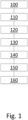
- Fig. 1 depicts a flow diagram of a method according to the present invention.
- the method is performed on a laboratory system or device as described above comprising at least one fluid buffer container, at least one fluid supply container fluidically connected to the fluid buffer container, the fluid supply container comprising a data storage for storing at least data related to the content of the fluid supply container, a scale for determining the content of the fluid buffer container and a control unit connected to the scale.
- control unit determines by means of the scale the content of the fluid buffer container (Vo).
- a second step 110 the control unit then determines if the content of the fluid buffer container (Vo) is below a given threshold. If the content of the fluid buffer container (Vo) is above the given threshold, the method is stopped and the system or device is operated without any further steps until the method is triggered again, e.g. when new orders for performing further activities by the system or device are received.
- control unit determines the filling amount of fluid (FA) to be supplied to the fluid buffer container from the fluid supply container.
- the data related to the content of the fluid supply container (VSo) in the data storage of the fluid supply container is updated by subtracting the filling amount (FA) from the content of the fluid supply container (VSo), therefore setting the content of the fluid supply container to VS 0 - FA.
- step 130 the filling amount (FA) of fluid is supplied from the fluid supply container to the fluid buffer container.
- control unit determines again in step 140 by means of the scale the content of the fluid buffer container (V 1 ) and then, in step 150, if the content of the fluid buffer container (V 1 ) corresponds to the expected content of the fluid buffer container (Vo + FA).
- step 150 it is determined that the content of the fluid buffer container (V 1 ) does not correspond to the expected content (Vo + FA)
- the data related to the content of the fluid supply container in the data storage of the fluid supply container is updated accordingly by subtracting the actually delivered filling amount (V 1 - Vo) from the content of the fluid supply container VSo in a further step 160.
Landscapes
- Physics & Mathematics (AREA)
- Health & Medical Sciences (AREA)
- Life Sciences & Earth Sciences (AREA)
- Chemical & Material Sciences (AREA)
- Analytical Chemistry (AREA)
- Biochemistry (AREA)
- General Health & Medical Sciences (AREA)
- General Physics & Mathematics (AREA)
- Immunology (AREA)
- Pathology (AREA)
- Filling Of Jars Or Cans And Processes For Cleaning And Sealing Jars (AREA)
- Loading And Unloading Of Fuel Tanks Or Ships (AREA)
Priority Applications (1)
| Application Number | Priority Date | Filing Date | Title |
|---|---|---|---|
| EP21208942.9A EP4184177B1 (de) | 2021-11-18 | 2021-11-18 | Verfahren zur fluidvolumenverfolgung in einem laborsystem oder -gerät |
Applications Claiming Priority (1)
| Application Number | Priority Date | Filing Date | Title |
|---|---|---|---|
| EP21208942.9A EP4184177B1 (de) | 2021-11-18 | 2021-11-18 | Verfahren zur fluidvolumenverfolgung in einem laborsystem oder -gerät |
Publications (2)
| Publication Number | Publication Date |
|---|---|
| EP4184177A1 true EP4184177A1 (de) | 2023-05-24 |
| EP4184177B1 EP4184177B1 (de) | 2025-03-26 |
Family
ID=78828045
Family Applications (1)
| Application Number | Title | Priority Date | Filing Date |
|---|---|---|---|
| EP21208942.9A Active EP4184177B1 (de) | 2021-11-18 | 2021-11-18 | Verfahren zur fluidvolumenverfolgung in einem laborsystem oder -gerät |
Country Status (1)
| Country | Link |
|---|---|
| EP (1) | EP4184177B1 (de) |
Citations (4)
| Publication number | Priority date | Publication date | Assignee | Title |
|---|---|---|---|---|
| US20110223682A1 (en) * | 2010-03-11 | 2011-09-15 | Sysmex Corporation | Sample analyzer and reagent management method |
| US20130280129A1 (en) * | 2010-11-29 | 2013-10-24 | Roche Diagnostics Operations Inc. | Automatic analyzer |
| US20190391170A1 (en) * | 2015-07-23 | 2019-12-26 | Meso Scale Technologies, Llc. | Integrated Consumable Data Management System & Platform |
| US20200003768A1 (en) * | 2013-06-19 | 2020-01-02 | Roche Diagnostics Operations, Inc. | Electrochemiluminescence method of detecting an analyte in a liquid sample and analysis system |
-
2021
- 2021-11-18 EP EP21208942.9A patent/EP4184177B1/de active Active
Patent Citations (4)
| Publication number | Priority date | Publication date | Assignee | Title |
|---|---|---|---|---|
| US20110223682A1 (en) * | 2010-03-11 | 2011-09-15 | Sysmex Corporation | Sample analyzer and reagent management method |
| US20130280129A1 (en) * | 2010-11-29 | 2013-10-24 | Roche Diagnostics Operations Inc. | Automatic analyzer |
| US20200003768A1 (en) * | 2013-06-19 | 2020-01-02 | Roche Diagnostics Operations, Inc. | Electrochemiluminescence method of detecting an analyte in a liquid sample and analysis system |
| US20190391170A1 (en) * | 2015-07-23 | 2019-12-26 | Meso Scale Technologies, Llc. | Integrated Consumable Data Management System & Platform |
Also Published As
| Publication number | Publication date |
|---|---|
| EP4184177B1 (de) | 2025-03-26 |
Similar Documents
| Publication | Publication Date | Title |
|---|---|---|
| JP5643339B2 (ja) | 自動分析装置 | |
| JP6602753B2 (ja) | 自動分析装置 | |
| EP2120052A1 (de) | Analysevorrichtung und analyseverfahren | |
| CN103748472A (zh) | 自动分析装置 | |
| US11519770B1 (en) | Systems and methods for tracking fuel deliveries | |
| JP2011117815A (ja) | 液体クロマトグラフ装置、および液体クロマトグラフ装置の管理方法 | |
| EP4184177B1 (de) | Verfahren zur fluidvolumenverfolgung in einem laborsystem oder -gerät | |
| US20190087918A1 (en) | Logistics method and system for planning sequencing of bulk material containers | |
| US20090149968A1 (en) | Control apparatus, control method, and computer program product | |
| JP2010108117A (ja) | Rfidを用いた生産管理システム | |
| JP4405864B2 (ja) | 製品不正積み込み防止支援システム | |
| US12292420B2 (en) | Control of sample separation based on analysis of mobile phase supply from mobile phase container | |
| JP3157618B2 (ja) | 原料在庫管理装置 | |
| US10417610B2 (en) | System and method for verifying a load placed in one or more trucks | |
| JP4520128B2 (ja) | 粘性材料供給装置 | |
| JPS61190494A (ja) | 給油方式 | |
| EP3783550A1 (de) | Nutzungsverwaltung für komponente einer flugzeug-bodenbetankungsanlage | |
| CN121961436A (zh) | 试剂管理系统及试剂管理方法 | |
| CN114380007A (zh) | 一种输砂系统的控制方法、装置、设备及存储介质 | |
| US10288472B2 (en) | Method and apparatus for compensation of wind effects on measured weights | |
| US20070175976A1 (en) | Record management system and method to trace chemicals | |
| JP7536561B2 (ja) | 監視制御装置および不動作原因表示方法 | |
| JPH06208576A (ja) | 在庫管理装置 | |
| CN119790417A (zh) | 用于自动确定灌装线中介质的消耗数据的方法及用于执行该方法的装置 | |
| JPH0948492A (ja) | 貯蔵量管理装置 |
Legal Events
| Date | Code | Title | Description |
|---|---|---|---|
| PUAI | Public reference made under article 153(3) epc to a published international application that has entered the european phase |
Free format text: ORIGINAL CODE: 0009012 |
|
| STAA | Information on the status of an ep patent application or granted ep patent |
Free format text: STATUS: THE APPLICATION HAS BEEN PUBLISHED |
|
| AK | Designated contracting states |
Kind code of ref document: A1 Designated state(s): AL AT BE BG CH CY CZ DE DK EE ES FI FR GB GR HR HU IE IS IT LI LT LU LV MC MK MT NL NO PL PT RO RS SE SI SK SM TR |
|
| STAA | Information on the status of an ep patent application or granted ep patent |
Free format text: STATUS: REQUEST FOR EXAMINATION WAS MADE |
|
| 17P | Request for examination filed |
Effective date: 20231124 |
|
| RBV | Designated contracting states (corrected) |
Designated state(s): AL AT BE BG CH CY CZ DE DK EE ES FI FR GB GR HR HU IE IS IT LI LT LU LV MC MK MT NL NO PL PT RO RS SE SI SK SM TR |
|
| GRAP | Despatch of communication of intention to grant a patent |
Free format text: ORIGINAL CODE: EPIDOSNIGR1 |
|
| STAA | Information on the status of an ep patent application or granted ep patent |
Free format text: STATUS: GRANT OF PATENT IS INTENDED |
|
| INTG | Intention to grant announced |
Effective date: 20241122 |
|
| GRAS | Grant fee paid |
Free format text: ORIGINAL CODE: EPIDOSNIGR3 |
|
| GRAA | (expected) grant |
Free format text: ORIGINAL CODE: 0009210 |
|
| STAA | Information on the status of an ep patent application or granted ep patent |
Free format text: STATUS: THE PATENT HAS BEEN GRANTED |
|
| AK | Designated contracting states |
Kind code of ref document: B1 Designated state(s): AL AT BE BG CH CY CZ DE DK EE ES FI FR GB GR HR HU IE IS IT LI LT LU LV MC MK MT NL NO PL PT RO RS SE SI SK SM TR |
|
| REG | Reference to a national code |
Ref country code: GB Ref legal event code: FG4D |
|
| REG | Reference to a national code |
Ref country code: CH Ref legal event code: EP |
|
| REG | Reference to a national code |
Ref country code: DE Ref legal event code: R096 Ref document number: 602021028072 Country of ref document: DE |
|
| REG | Reference to a national code |
Ref country code: IE Ref legal event code: FG4D |
|
| PG25 | Lapsed in a contracting state [announced via postgrant information from national office to epo] |
Ref country code: RS Free format text: LAPSE BECAUSE OF FAILURE TO SUBMIT A TRANSLATION OF THE DESCRIPTION OR TO PAY THE FEE WITHIN THE PRESCRIBED TIME-LIMIT Effective date: 20250626 |
|
| PG25 | Lapsed in a contracting state [announced via postgrant information from national office to epo] |
Ref country code: FI Free format text: LAPSE BECAUSE OF FAILURE TO SUBMIT A TRANSLATION OF THE DESCRIPTION OR TO PAY THE FEE WITHIN THE PRESCRIBED TIME-LIMIT Effective date: 20250326 |
|
| REG | Reference to a national code |
Ref country code: LT Ref legal event code: MG9D |
|
| PG25 | Lapsed in a contracting state [announced via postgrant information from national office to epo] |
Ref country code: NO Free format text: LAPSE BECAUSE OF FAILURE TO SUBMIT A TRANSLATION OF THE DESCRIPTION OR TO PAY THE FEE WITHIN THE PRESCRIBED TIME-LIMIT Effective date: 20250626 |
|
| PG25 | Lapsed in a contracting state [announced via postgrant information from national office to epo] |
Ref country code: HR Free format text: LAPSE BECAUSE OF FAILURE TO SUBMIT A TRANSLATION OF THE DESCRIPTION OR TO PAY THE FEE WITHIN THE PRESCRIBED TIME-LIMIT Effective date: 20250326 |
|
| PG25 | Lapsed in a contracting state [announced via postgrant information from national office to epo] |
Ref country code: LV Free format text: LAPSE BECAUSE OF FAILURE TO SUBMIT A TRANSLATION OF THE DESCRIPTION OR TO PAY THE FEE WITHIN THE PRESCRIBED TIME-LIMIT Effective date: 20250326 |
|
| PG25 | Lapsed in a contracting state [announced via postgrant information from national office to epo] |
Ref country code: BG Free format text: LAPSE BECAUSE OF FAILURE TO SUBMIT A TRANSLATION OF THE DESCRIPTION OR TO PAY THE FEE WITHIN THE PRESCRIBED TIME-LIMIT Effective date: 20250326 Ref country code: GR Free format text: LAPSE BECAUSE OF FAILURE TO SUBMIT A TRANSLATION OF THE DESCRIPTION OR TO PAY THE FEE WITHIN THE PRESCRIBED TIME-LIMIT Effective date: 20250627 |
|
| REG | Reference to a national code |
Ref country code: NL Ref legal event code: MP Effective date: 20250326 |
|
| PG25 | Lapsed in a contracting state [announced via postgrant information from national office to epo] |
Ref country code: NL Free format text: LAPSE BECAUSE OF FAILURE TO SUBMIT A TRANSLATION OF THE DESCRIPTION OR TO PAY THE FEE WITHIN THE PRESCRIBED TIME-LIMIT Effective date: 20250326 |
|
| PG25 | Lapsed in a contracting state [announced via postgrant information from national office to epo] |
Ref country code: SE Free format text: LAPSE BECAUSE OF FAILURE TO SUBMIT A TRANSLATION OF THE DESCRIPTION OR TO PAY THE FEE WITHIN THE PRESCRIBED TIME-LIMIT Effective date: 20250326 |
|
| REG | Reference to a national code |
Ref country code: AT Ref legal event code: MK05 Ref document number: 1779430 Country of ref document: AT Kind code of ref document: T Effective date: 20250326 |
|
| PG25 | Lapsed in a contracting state [announced via postgrant information from national office to epo] |
Ref country code: SM Free format text: LAPSE BECAUSE OF FAILURE TO SUBMIT A TRANSLATION OF THE DESCRIPTION OR TO PAY THE FEE WITHIN THE PRESCRIBED TIME-LIMIT Effective date: 20250326 |
|
| PG25 | Lapsed in a contracting state [announced via postgrant information from national office to epo] |
Ref country code: ES Free format text: LAPSE BECAUSE OF FAILURE TO SUBMIT A TRANSLATION OF THE DESCRIPTION OR TO PAY THE FEE WITHIN THE PRESCRIBED TIME-LIMIT Effective date: 20250326 Ref country code: PT Free format text: LAPSE BECAUSE OF FAILURE TO SUBMIT A TRANSLATION OF THE DESCRIPTION OR TO PAY THE FEE WITHIN THE PRESCRIBED TIME-LIMIT Effective date: 20250728 |
|
| PG25 | Lapsed in a contracting state [announced via postgrant information from national office to epo] |
Ref country code: PL Free format text: LAPSE BECAUSE OF FAILURE TO SUBMIT A TRANSLATION OF THE DESCRIPTION OR TO PAY THE FEE WITHIN THE PRESCRIBED TIME-LIMIT Effective date: 20250326 Ref country code: IT Free format text: LAPSE BECAUSE OF FAILURE TO SUBMIT A TRANSLATION OF THE DESCRIPTION OR TO PAY THE FEE WITHIN THE PRESCRIBED TIME-LIMIT Effective date: 20250326 |
|
| PG25 | Lapsed in a contracting state [announced via postgrant information from national office to epo] |
Ref country code: AT Free format text: LAPSE BECAUSE OF FAILURE TO SUBMIT A TRANSLATION OF THE DESCRIPTION OR TO PAY THE FEE WITHIN THE PRESCRIBED TIME-LIMIT Effective date: 20250326 |
|
| PG25 | Lapsed in a contracting state [announced via postgrant information from national office to epo] |
Ref country code: EE Free format text: LAPSE BECAUSE OF FAILURE TO SUBMIT A TRANSLATION OF THE DESCRIPTION OR TO PAY THE FEE WITHIN THE PRESCRIBED TIME-LIMIT Effective date: 20250326 |
|
| PG25 | Lapsed in a contracting state [announced via postgrant information from national office to epo] |
Ref country code: RO Free format text: LAPSE BECAUSE OF FAILURE TO SUBMIT A TRANSLATION OF THE DESCRIPTION OR TO PAY THE FEE WITHIN THE PRESCRIBED TIME-LIMIT Effective date: 20250326 |
|
| PG25 | Lapsed in a contracting state [announced via postgrant information from national office to epo] |
Ref country code: SK Free format text: LAPSE BECAUSE OF FAILURE TO SUBMIT A TRANSLATION OF THE DESCRIPTION OR TO PAY THE FEE WITHIN THE PRESCRIBED TIME-LIMIT Effective date: 20250326 |
|
| PG25 | Lapsed in a contracting state [announced via postgrant information from national office to epo] |
Ref country code: IS Free format text: LAPSE BECAUSE OF FAILURE TO SUBMIT A TRANSLATION OF THE DESCRIPTION OR TO PAY THE FEE WITHIN THE PRESCRIBED TIME-LIMIT Effective date: 20250726 |
|
| REG | Reference to a national code |
Ref country code: CH Ref legal event code: U11 Free format text: ST27 STATUS EVENT CODE: U-0-0-U10-U11 (AS PROVIDED BY THE NATIONAL OFFICE) Effective date: 20251201 |
|
| REG | Reference to a national code |
Ref country code: DE Ref legal event code: R097 Ref document number: 602021028072 Country of ref document: DE |
|
| PGFP | Annual fee paid to national office [announced via postgrant information from national office to epo] |
Ref country code: DE Payment date: 20251022 Year of fee payment: 5 |
|
| PGFP | Annual fee paid to national office [announced via postgrant information from national office to epo] |
Ref country code: GB Payment date: 20251023 Year of fee payment: 5 |
|
| PG25 | Lapsed in a contracting state [announced via postgrant information from national office to epo] |
Ref country code: DK Free format text: LAPSE BECAUSE OF FAILURE TO SUBMIT A TRANSLATION OF THE DESCRIPTION OR TO PAY THE FEE WITHIN THE PRESCRIBED TIME-LIMIT Effective date: 20250326 |
|
| PGFP | Annual fee paid to national office [announced via postgrant information from national office to epo] |
Ref country code: FR Payment date: 20251023 Year of fee payment: 5 |
|
| PGFP | Annual fee paid to national office [announced via postgrant information from national office to epo] |
Ref country code: CH Payment date: 20251201 Year of fee payment: 5 |
|
| PG25 | Lapsed in a contracting state [announced via postgrant information from national office to epo] |
Ref country code: CZ Free format text: LAPSE BECAUSE OF FAILURE TO SUBMIT A TRANSLATION OF THE DESCRIPTION OR TO PAY THE FEE WITHIN THE PRESCRIBED TIME-LIMIT Effective date: 20250326 |
|
| PLBE | No opposition filed within time limit |
Free format text: ORIGINAL CODE: 0009261 |
|
| STAA | Information on the status of an ep patent application or granted ep patent |
Free format text: STATUS: NO OPPOSITION FILED WITHIN TIME LIMIT |
|
| REG | Reference to a national code |
Ref country code: CH Ref legal event code: L10 Free format text: ST27 STATUS EVENT CODE: U-0-0-L10-L00 (AS PROVIDED BY THE NATIONAL OFFICE) Effective date: 20260211 |
|
| 26N | No opposition filed |
Effective date: 20260105 |