EP4198231A1 - Système d'inclinaison de porte et procédé de réglage d'un système d'inclinaison de porte - Google Patents
Système d'inclinaison de porte et procédé de réglage d'un système d'inclinaison de porte Download PDFInfo
- Publication number
- EP4198231A1 EP4198231A1 EP21214830.8A EP21214830A EP4198231A1 EP 4198231 A1 EP4198231 A1 EP 4198231A1 EP 21214830 A EP21214830 A EP 21214830A EP 4198231 A1 EP4198231 A1 EP 4198231A1
- Authority
- EP
- European Patent Office
- Prior art keywords
- socket
- door
- tilting system
- relative
- outer socket
- Prior art date
- Legal status (The legal status is an assumption and is not a legal conclusion. Google has not performed a legal analysis and makes no representation as to the accuracy of the status listed.)
- Granted
Links
Images




Classifications
-
- B—PERFORMING OPERATIONS; TRANSPORTING
- B60—VEHICLES IN GENERAL
- B60J—WINDOWS, WINDSCREENS, NON-FIXED ROOFS, DOORS, OR SIMILAR DEVICES FOR VEHICLES; REMOVABLE EXTERNAL PROTECTIVE COVERINGS SPECIALLY ADAPTED FOR VEHICLES
- B60J5/00—Doors
- B60J5/04—Doors arranged at the vehicle sides
- B60J5/06—Doors arranged at the vehicle sides slidable; foldable
-
- E—FIXED CONSTRUCTIONS
- E05—LOCKS; KEYS; WINDOW OR DOOR FITTINGS; SAFES
- E05D—HINGES OR SUSPENSION DEVICES FOR DOORS, WINDOWS OR WINGS
- E05D15/00—Suspension arrangements for wings
- E05D15/06—Suspension arrangements for wings for wings sliding horizontally more or less in their own plane
- E05D15/10—Suspension arrangements for wings for wings sliding horizontally more or less in their own plane movable out of one plane into a second parallel plane
- E05D15/1005—Suspension arrangements for wings for wings sliding horizontally more or less in their own plane movable out of one plane into a second parallel plane the wing being supported on arms movable in horizontal planes
- E05D15/101—Suspension arrangements for wings for wings sliding horizontally more or less in their own plane movable out of one plane into a second parallel plane the wing being supported on arms movable in horizontal planes specially adapted for vehicles
-
- E—FIXED CONSTRUCTIONS
- E05—LOCKS; KEYS; WINDOW OR DOOR FITTINGS; SAFES
- E05D—HINGES OR SUSPENSION DEVICES FOR DOORS, WINDOWS OR WINGS
- E05D5/00—Construction of single parts, e.g. the parts for attachment
- E05D5/10—Pins, sockets or sleeves; Removable pins
- E05D5/14—Construction of sockets or sleeves
-
- E—FIXED CONSTRUCTIONS
- E05—LOCKS; KEYS; WINDOW OR DOOR FITTINGS; SAFES
- E05D—HINGES OR SUSPENSION DEVICES FOR DOORS, WINDOWS OR WINGS
- E05D7/00—Hinges or pivots of special construction
- E05D7/0009—Adjustable hinges
- E05D7/0018—Adjustable hinges at the hinge axis
- E05D7/0045—Adjustable hinges at the hinge axis in a radial direction
- E05D7/0054—Adjustable hinges at the hinge axis in a radial direction by means of eccentric parts
-
- E—FIXED CONSTRUCTIONS
- E05—LOCKS; KEYS; WINDOW OR DOOR FITTINGS; SAFES
- E05D—HINGES OR SUSPENSION DEVICES FOR DOORS, WINDOWS OR WINGS
- E05D15/00—Suspension arrangements for wings
- E05D15/06—Suspension arrangements for wings for wings sliding horizontally more or less in their own plane
- E05D15/10—Suspension arrangements for wings for wings sliding horizontally more or less in their own plane movable out of one plane into a second parallel plane
- E05D2015/1028—Suspension arrangements for wings for wings sliding horizontally more or less in their own plane movable out of one plane into a second parallel plane with only the wing moving transversely
- E05D2015/1031—Suspension arrangements for wings for wings sliding horizontally more or less in their own plane movable out of one plane into a second parallel plane with only the wing moving transversely the wing supported on arms extending from the carriage
-
- E—FIXED CONSTRUCTIONS
- E05—LOCKS; KEYS; WINDOW OR DOOR FITTINGS; SAFES
- E05Y—INDEXING SCHEME ASSOCIATED WITH SUBCLASSES E05D AND E05F, RELATING TO CONSTRUCTION ELEMENTS, ELECTRIC CONTROL, POWER SUPPLY, POWER SIGNAL OR TRANSMISSION, USER INTERFACES, MOUNTING OR COUPLING, DETAILS, ACCESSORIES, AUXILIARY OPERATIONS NOT OTHERWISE PROVIDED FOR, APPLICATION THEREOF
- E05Y2201/00—Constructional elements; Accessories therefor
- E05Y2201/60—Suspension or transmission members; Accessories therefor
- E05Y2201/622—Suspension or transmission members elements
- E05Y2201/624—Arms
-
- E—FIXED CONSTRUCTIONS
- E05—LOCKS; KEYS; WINDOW OR DOOR FITTINGS; SAFES
- E05Y—INDEXING SCHEME ASSOCIATED WITH SUBCLASSES E05D AND E05F, RELATING TO CONSTRUCTION ELEMENTS, ELECTRIC CONTROL, POWER SUPPLY, POWER SIGNAL OR TRANSMISSION, USER INTERFACES, MOUNTING OR COUPLING, DETAILS, ACCESSORIES, AUXILIARY OPERATIONS NOT OTHERWISE PROVIDED FOR, APPLICATION THEREOF
- E05Y2201/00—Constructional elements; Accessories therefor
- E05Y2201/60—Suspension or transmission members; Accessories therefor
- E05Y2201/622—Suspension or transmission members elements
- E05Y2201/628—Bearings
- E05Y2201/632—Sleeves
-
- E—FIXED CONSTRUCTIONS
- E05—LOCKS; KEYS; WINDOW OR DOOR FITTINGS; SAFES
- E05Y—INDEXING SCHEME ASSOCIATED WITH SUBCLASSES E05D AND E05F, RELATING TO CONSTRUCTION ELEMENTS, ELECTRIC CONTROL, POWER SUPPLY, POWER SIGNAL OR TRANSMISSION, USER INTERFACES, MOUNTING OR COUPLING, DETAILS, ACCESSORIES, AUXILIARY OPERATIONS NOT OTHERWISE PROVIDED FOR, APPLICATION THEREOF
- E05Y2201/00—Constructional elements; Accessories therefor
- E05Y2201/60—Suspension or transmission members; Accessories therefor
- E05Y2201/622—Suspension or transmission members elements
- E05Y2201/638—Cams; Ramps
-
- E—FIXED CONSTRUCTIONS
- E05—LOCKS; KEYS; WINDOW OR DOOR FITTINGS; SAFES
- E05Y—INDEXING SCHEME ASSOCIATED WITH SUBCLASSES E05D AND E05F, RELATING TO CONSTRUCTION ELEMENTS, ELECTRIC CONTROL, POWER SUPPLY, POWER SIGNAL OR TRANSMISSION, USER INTERFACES, MOUNTING OR COUPLING, DETAILS, ACCESSORIES, AUXILIARY OPERATIONS NOT OTHERWISE PROVIDED FOR, APPLICATION THEREOF
- E05Y2201/00—Constructional elements; Accessories therefor
- E05Y2201/60—Suspension or transmission members; Accessories therefor
- E05Y2201/622—Suspension or transmission members elements
- E05Y2201/682—Pins
-
- E—FIXED CONSTRUCTIONS
- E05—LOCKS; KEYS; WINDOW OR DOOR FITTINGS; SAFES
- E05Y—INDEXING SCHEME ASSOCIATED WITH SUBCLASSES E05D AND E05F, RELATING TO CONSTRUCTION ELEMENTS, ELECTRIC CONTROL, POWER SUPPLY, POWER SIGNAL OR TRANSMISSION, USER INTERFACES, MOUNTING OR COUPLING, DETAILS, ACCESSORIES, AUXILIARY OPERATIONS NOT OTHERWISE PROVIDED FOR, APPLICATION THEREOF
- E05Y2600/00—Mounting or coupling arrangements for elements provided for in this subclass
- E05Y2600/10—Adjustable
-
- E—FIXED CONSTRUCTIONS
- E05—LOCKS; KEYS; WINDOW OR DOOR FITTINGS; SAFES
- E05Y—INDEXING SCHEME ASSOCIATED WITH SUBCLASSES E05D AND E05F, RELATING TO CONSTRUCTION ELEMENTS, ELECTRIC CONTROL, POWER SUPPLY, POWER SIGNAL OR TRANSMISSION, USER INTERFACES, MOUNTING OR COUPLING, DETAILS, ACCESSORIES, AUXILIARY OPERATIONS NOT OTHERWISE PROVIDED FOR, APPLICATION THEREOF
- E05Y2600/00—Mounting or coupling arrangements for elements provided for in this subclass
- E05Y2600/10—Adjustable
- E05Y2600/12—Adjustable by manual operation
-
- E—FIXED CONSTRUCTIONS
- E05—LOCKS; KEYS; WINDOW OR DOOR FITTINGS; SAFES
- E05Y—INDEXING SCHEME ASSOCIATED WITH SUBCLASSES E05D AND E05F, RELATING TO CONSTRUCTION ELEMENTS, ELECTRIC CONTROL, POWER SUPPLY, POWER SIGNAL OR TRANSMISSION, USER INTERFACES, MOUNTING OR COUPLING, DETAILS, ACCESSORIES, AUXILIARY OPERATIONS NOT OTHERWISE PROVIDED FOR, APPLICATION THEREOF
- E05Y2600/00—Mounting or coupling arrangements for elements provided for in this subclass
- E05Y2600/50—Mounting methods; Positioning
- E05Y2600/502—Clamping
-
- E—FIXED CONSTRUCTIONS
- E05—LOCKS; KEYS; WINDOW OR DOOR FITTINGS; SAFES
- E05Y—INDEXING SCHEME ASSOCIATED WITH SUBCLASSES E05D AND E05F, RELATING TO CONSTRUCTION ELEMENTS, ELECTRIC CONTROL, POWER SUPPLY, POWER SIGNAL OR TRANSMISSION, USER INTERFACES, MOUNTING OR COUPLING, DETAILS, ACCESSORIES, AUXILIARY OPERATIONS NOT OTHERWISE PROVIDED FOR, APPLICATION THEREOF
- E05Y2600/00—Mounting or coupling arrangements for elements provided for in this subclass
- E05Y2600/50—Mounting methods; Positioning
- E05Y2600/56—Positioning, e.g. re-positioning, or pre-mounting
-
- E—FIXED CONSTRUCTIONS
- E05—LOCKS; KEYS; WINDOW OR DOOR FITTINGS; SAFES
- E05Y—INDEXING SCHEME ASSOCIATED WITH SUBCLASSES E05D AND E05F, RELATING TO CONSTRUCTION ELEMENTS, ELECTRIC CONTROL, POWER SUPPLY, POWER SIGNAL OR TRANSMISSION, USER INTERFACES, MOUNTING OR COUPLING, DETAILS, ACCESSORIES, AUXILIARY OPERATIONS NOT OTHERWISE PROVIDED FOR, APPLICATION THEREOF
- E05Y2600/00—Mounting or coupling arrangements for elements provided for in this subclass
- E05Y2600/60—Mounting or coupling members; Accessories therefor
- E05Y2600/632—Screws
-
- E—FIXED CONSTRUCTIONS
- E05—LOCKS; KEYS; WINDOW OR DOOR FITTINGS; SAFES
- E05Y—INDEXING SCHEME ASSOCIATED WITH SUBCLASSES E05D AND E05F, RELATING TO CONSTRUCTION ELEMENTS, ELECTRIC CONTROL, POWER SUPPLY, POWER SIGNAL OR TRANSMISSION, USER INTERFACES, MOUNTING OR COUPLING, DETAILS, ACCESSORIES, AUXILIARY OPERATIONS NOT OTHERWISE PROVIDED FOR, APPLICATION THEREOF
- E05Y2800/00—Details, accessories and auxiliary operations not otherwise provided for
- E05Y2800/26—Form or shape
- E05Y2800/292—Form or shape having apertures
- E05Y2800/296—Slots
-
- E—FIXED CONSTRUCTIONS
- E05—LOCKS; KEYS; WINDOW OR DOOR FITTINGS; SAFES
- E05Y—INDEXING SCHEME ASSOCIATED WITH SUBCLASSES E05D AND E05F, RELATING TO CONSTRUCTION ELEMENTS, ELECTRIC CONTROL, POWER SUPPLY, POWER SIGNAL OR TRANSMISSION, USER INTERFACES, MOUNTING OR COUPLING, DETAILS, ACCESSORIES, AUXILIARY OPERATIONS NOT OTHERWISE PROVIDED FOR, APPLICATION THEREOF
- E05Y2900/00—Application of doors, windows, wings or fittings thereof
- E05Y2900/50—Application of doors, windows, wings or fittings thereof for vehicles
- E05Y2900/53—Type of wing
- E05Y2900/531—Doors
Definitions
- the present disclosure relates to a door tilting system for a slidable vehicle door.
- the door tilting system is forming part of a pivoting joint between the vehicle door and a movable arm structure connecting the vehicle door to a vehicle body structure.
- the disclosure further relates to a vehicle comprising at least one door tilting system and a method for adjusting a door tilting system for a slidable vehicle door.
- vehicle doors There are different types of vehicle doors that are allowing access to an interior compartment of the vehicle, and conventional door constructions are for example hinged vehicle doors that are pivotably connected to a vehicle body structure via hinges, or sliding vehicle doors that are slidingly connected to a vehicle body structure via rails and movable arm structures.
- hinged vehicle doors that are pivotably connected to a vehicle body structure via hinges
- sliding vehicle doors that are slidingly connected to a vehicle body structure via rails and movable arm structures.
- the door connection geometry is commonly set by three connection points formed by two hinges and a door-locking latch.
- the door connection geometry is commonly set by three connection points formed by rails and movable arm structures. These connection points can be adjusted to give correct door position relative to the vehicle body structure in longitudinal, lateral and vertical vehicle directions.
- a correct door position is essential for a sealed connection between the vehicle door and the vehicle body structure, preventing noise, dust, and other contaminants, from entering the interior compartment.
- a correct door position is further essential for an aesthetically correct positioning of the vehicle door relative to the vehicle body structure.
- Door adjustment systems are often complicated and the door adjustment processes are often time-consuming operational steps when assembling the vehicle. There is thus a need for an improved way of adjusting the vehicle doors relative to the vehicle body structure for a fast and efficient vehicle assembly process.
- An object of the present disclosure is to provide a door tilting system for a slidable vehicle door, a vehicle comprising at least one door tilting system, and a method for adjusting a door tilting system for a slidable vehicle door where the previously mentioned problems are avoided.
- This object is at least partly achieved by the features of the independent claims.
- the dependent claims contain further developments of the door tilting system for a slidable vehicle door and the method for adjusting a door tilting system for a slidable vehicle door.
- the disclosure concerns a door tilting system for a slidable vehicle door, where the door tilting system is forming part of a pivoting joint between the vehicle door and a movable arm structure connecting the vehicle door to a vehicle body structure.
- the door tilting system comprises an inner socket and an outer socket, where the inner socket is arranged inside the outer socket and rotatably arranged relative to the outer socket.
- the inner socket comprises a receiving opening configured for receiving a fastening device, where the receiving opening has an elongated configuration and is extending in a first direction along a first axis through the inner socket.
- the door tilting system is configured for changing the first direction of the receiving opening relative to the outer socket upon rotational displacement of the inner socket relative to the outer socket.
- the door tilting system is enabling a simple and efficient way to adjust the vehicle door by changing the first direction of the receiving opening relative to the outer socket upon rotational displacement of the inner socket relative to the outer socket.
- the inner socket is thus rotated relative to the outer socket for achieving a correct door position, and by the rotational displacement a tilt angle of the fastening device is adjusted, which in turn is affecting the door position relative to a vehicle body structure to which the vehicle door is movably attached.
- a correct door position is important for a correct latching position of the vehicle door to the vehicle body structure, and for achieving a sealed connection between the vehicle door and the vehicle body structure, preventing noise, dust, and other contaminants, from entering the interior compartment.
- the simple adjustment through the rotational displacement between the inner socket and the outer socket is further essential for an aesthetically correct positioning of the vehicle door relative to the vehicle body structure.
- the simple door adjustment operation is enabling a fast and efficient vehicle assembly process.
- the slidable vehicle door is defined as any type of vehicle door that is connected to the vehicle body structure via one or more arm structures, where the one or more arm structures are pivoting relative to the vehicle door via pivoting joints allowing a longitudinal displacement of the vehicle door relative to the vehicle body structure, or allowing a combination of longitudinal and lateral displacement of the vehicle door relative to the vehicle body structure.
- the inner socket comprises an outer surface and the outer socket comprises an inner surface.
- the outer surface of the inner socket is arranged in connection to the inner surface of the outer socket, where upon rotational displacement of the inner socket relative to the outer socket, the outer surface of the inner socket is configured to move relative to the inner surface of the outer socket.
- the inner surface of the outer socket is forming an inner opening configured for receiving the inner socket.
- the inner opening is forming a channel-like structure in the outer socket that is configured for receiving the inner socket.
- the outer surface of the inner socket is arranged in connection to the inner surface of the outer socket, and upon rotational displacement of the inner socket relative to the outer socket, the inner socket is rotating within the inner opening of the outer socket.
- the inner opening suitably has a circular cross-sectional shape, allowing a rotational movement of the inner socket relative to the outer socket.
- the inner opening is extending through the outer socket.
- the inner opening is forming a channel-like or tube-like structure in the outer socket that is configured for receiving the inner socket.
- the inner opening suitably has a circular cross-sectional shape for allowing the rotational movement of the inner socket relative to the outer socket.
- the outer surface of the inner socket is arranged as a cylindrical surface
- the inner surface of the outer socket is arranged as a cylindrical surface.
- the cylindrical surfaces are allowing an efficient rotational displacement of the inner socket relative to the outer socket.
- the outer surface of the inner socket is extending in a second direction, where the second direction is different from the first direction. This extension in the second direction is enabling the tilt adjustment operation.
- the outer socket is connected to an outer end of the movable arm structure.
- the outer socket may be attached to or form an integrated structural part of the arm structure.
- the outer socket could for example be welded to the outer end of the arm structure for a strong and secure connection, or attached to the outer end of the arm structure with other suitable attachment means.
- the door tilting system further comprises a first bracket and a second bracket attached to the vehicle door.
- the outer socket and the inner socket are arranged between the first bracket and the second bracket. In this way, the outer socket and the inner socket are each extending between the first bracket and the second bracket.
- the first bracket comprises a first fastening opening and the second bracket comprises a second fastening opening.
- the fastening device is extending through the first fastening opening, the receiving opening, and the second fastening opening.
- This construction is enabling a firm connection between the components involved, and the second fastening opening may for example be threaded for engaging threads arranged on the fastening device for a secure connection between the vehicle door and the arm structure, via the brackets and the sockets.
- a slot is arranged in a side wall structure of the outer socket.
- the inner socket comprises a locking member extending from the inner socket through the slot to an outer side of the outer socket.
- the locking member is configured for releasably attaching the inner socket to the outer socket.
- the slot may have an elongated configuration and is extending through the side wall structure of the outer socket, forming an opening that is giving access to the inner socket from the outside surface of the outer socket. The locking member is allowed to move along the slot upon rotational displacement of the inner socket relative to the outer socket.
- the locking member is in an unlocked state unlocking the inner socket from the outer socket, allowing rotational displacement of the inner socket relative to the outer socket.
- the locking member is in a locked state locking the inner socket to the outer socket through frictional engagement between at least the locking member and the outer socket, preventing rotational displacement of the inner socket relative to the outer socket.
- the locking member is allowed to move along the slot in the unlocked state upon rotational displacement of the inner socket relative to the outer socket, and when the inner socket has reached a desired position, the locking member is arranged in the locked state for preventing rotational displacement of the inner socket relative to the outer socket.
- the locking member may extend from the inner socket through the slot to the outside of the outer socket. The locking and unlocking operations are in this way efficiently enabled from outside the outer socket.
- the inner socket comprises a threaded opening
- the locking member is arranged as a threaded screw configured for being in engagement with the threaded opening.
- the locking member In the locked state, the locking member is in contact with the outer socket.
- the locking member is with this configuration arranged as a screw that is extending from the inner socket through the slot to the outside of the outer socket.
- the locking member is threaded into the inner socket for enabling unlocking of the inner socket from the outer socket and locking of the inner socket to the outer socket.
- the disclosure further concerns a vehicle comprising at least one door tilting system for a slidable vehicle door, as described above.
- the disclosure further concerns a method for adjusting a door tilting system for a slidable vehicle door, where the door tilting system is forming part of a pivoting joint between the vehicle door and a movable arm structure connecting the vehicle door to a vehicle body structure.
- the door tilting system comprises an inner socket and an outer socket, where the inner socket is arranged inside the outer socket and rotatably arranged relative to the outer socket.
- the inner socket comprises a receiving opening configured for receiving a fastening device, where the receiving opening has an elongated configuration and is extending in a first direction along a first axis through the inner socket.
- the method comprises the steps: rotatably displacing the inner socket relative to the outer socket, wherein the rotational displacement of the inner socket relative to the outer socket is changing the first direction of the receiving opening relative to the outer socket.
- the method for adjusting the door tilting system door tilting is providing an efficient way to adjust the vehicle door through simple operational steps by changing the first direction of the receiving opening relative to the outer socket upon rotational displacement of the inner socket relative to the outer socket.
- the inner socket is according to the method being rotated relative to the outer socket for achieving a correct door position, and by the rotational displacement a tilt angle of the fastening device is adjusted, which in turn is affecting the door position relative to a vehicle body structure to which the vehicle door is movably attached.
- a correct door position is important for a correct latching position of the vehicle door to the vehicle body structure, and for achieving a sealed connection between the vehicle door and the vehicle body structure, preventing noise, dust, and other contaminants, from entering the interior compartment.
- the simple adjustment through the rotational displacement between the inner socket and the outer socket is essential for an aesthetically correct positioning of the vehicle door relative to the vehicle body structure.
- the simple door adjustment operation is further enabling a fast and efficient vehicle assembly process.
- a slot is arranged in a side wall structure of the outer socket.
- the inner socket comprises a locking member extending from the inner socket through the slot to an outer side of the outer socket.
- the locking member is configured for releasably attaching the inner socket to the outer socket.
- the method further comprises the steps: unlocking the inner socket from the outer socket by the locking member to an unlocked state for allowing rotational displacement of the inner socket relative to the outer socket; displacing the inner socket relative to the outer socket to a desired position; and locking the inner socket to the outer socket by the locking member to a locked state for preventing rotational displacement of the inner socket relative to the outer socket.
- the slot may have an elongated configuration and is extending through the side wall structure of the outer socket, forming an opening that is giving access to the inner socket from the outside surface of the outer socket.
- the locking member is allowed to move along the slot in the unlocked state upon rotational displacement of the inner socket relative to the outer socket, and when the inner socket has reached a desired position, the locking member is arranged in the locked state for preventing rotational displacement of the inner socket relative to the outer socket.
- the locking member may be arranged as a screw that is extending from the inner socket through the slot to the outside of the outer socket.
- the locking member is suitably threaded into the inner socket for enabling unlocking of the inner socket from the outer socket and locking of the inner socket to the outer socket. The locking and unlocking operations are with this configuration efficiently enabled from outside the outer socket.
- FIGS 1-2 schematically show a vehicle V with a slidable vehicle door D.
- the vehicle door D is connected to a vehicle body structure B and movably arranged between a closed door position and an open door position, as indicated with the double arrow in figure 1 .
- a closed door position access to an interior compartment I of the vehicle V via a door opening in the vehicle body structure B is prevented, and in the open door position, access to the interior compartment I of the vehicle V via the door opening in the vehicle body structure B is enabled.
- the vehicle door D is illustrated in an open door position for illustrative purposes.
- a door tilting system S for the slidable vehicle door D is schematically illustrated.
- the door tilting system S is forming part of a pivoting joint J between the vehicle door D and a movable arm structure A.
- the pivoting joint J is allowing the arm structure to pivot relative to the vehicle door D.
- the arm structure A is connecting the vehicle door D to the vehicle body structure B of the vehicle V.
- the vehicle door D is connected to the vehicle body structure B via two arm structures A arranged at the lower part of the vehicle door D, where each arm structure A is rotatably connected to the vehicle door D via a pivoting joint J.
- each arm structure A is allowed to rotate relative to the vehicle door D for an efficient displacement of the vehicle door D during door opening and closing operations.
- the arm structures A may have any suitable shape or configuration, and in the illustrated embodiment, the arm structures A are rotating in a horizontal plane, or essentially horizontal plane, when opening and closing the vehicle door D.
- slidable vehicle door for all embodiments is defined as any type of vehicle door that is connected to a vehicle body structure via one or more arm structures, where the one or more arm structures are pivoting relative to the vehicle door via pivoting joints allowing a longitudinal displacement of the vehicle door relative to the vehicle body structure, or allowing a combination of longitudinal and lateral displacement of the vehicle door relative to the vehicle body structure.
- the vehicle door D is connected to the vehicle body structure B, as understood from figure 2 , and in the illustrated embodiment two arm structures A are arranged at the lower part of the vehicle door D, as shown in figure 3 .
- the door tilting system S may be arranged in each pivoting joint J between the vehicle door D and respective movable arm structure A.
- Each arm structure A comprises an inner end A IE arranged in connection to the vehicle body structure B and an outer end A OE arranged in connection to the vehicle door D.
- the inner ends A IE of the arm structures A may suitable be rotatably arranged relative to the vehicle body structure B and connected to track structures or similar arrangements for longitudinal displacement in a lower sill area of the vehicle body structure B at the door opening, as indicated in figure 2 .
- each arm structure A is thus arranged as a lower arm for holding and displacing the vehicle door D relative to the vehicle body structure B, and each arm structure A is therefore suitably connected to a lower part of the vehicle body structure B.
- the vehicle door D may further have an upper arm structure for enabling the movable connection between the vehicle door D and the vehicle body structure B.
- one or more arm structures A could connect the vehicle door D to any suitable part of the vehicle body structure B.
- the vehicle door D may in other embodiments be arranged with any suitable number of arm structures A arranged at the lower part and/or the upper part of the vehicle door D, and one or more of the joints J between the arm structures A and the vehicle door D may be arranged with the door tilting system S.
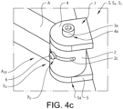
- Embodiments of the door tilting system S are shown in figures 4a-c , 5a-d , and 6a-d .
- the door tilting system S comprises an inner socket 1 and an outer socket 2.
- the inner socket 1 is arranged inside the outer socket 2 and rotatably arranged relative to the outer socket 2, as illustrated with the double arrow in figure 5a and 6a .
- the inner socket 1 comprises a receiving opening 3, and the receiving opening 3 is configured for receiving a fastening device 3a, such as a screw, a bolt, locking pin, or other suitable fastening element, for connecting the arm structure A to the vehicle door D.
- the receiving opening 3 has an elongated configuration and is extending in a first direction D1 along a first axis A1 through the inner socket 1.
- the receiving opening 3 is thus extending through the inner socket 1, and in the illustrated embodiment the receiving opening 3 has a tube-like or channel-like shape with dimensions suitable for receiving the fastening device 3a without too much play between the receiving opening 3 and the fastening device 3a, as understood from figures 5c-d and 6c-d .
- the door tilting system S further comprises a first bracket 4 and a second bracket 5 attached to the vehicle door D, as shown in figures 4a-c , 5c-d , and 6c-d .
- the outer socket 2 and the inner socket 1 are arranged between the first bracket 4 and the second bracket 5. In this way, the outer socket 2 and the inner socket 1 are each extending between the first bracket 4 and the second bracket 5, as understood from figures 5c-d and 6c-d .
- the first bracket 4 comprises a first fastening opening 4a and the second bracket 5 comprises a second fastening opening 5a, and in an assembled state S A of the door tilting system S, as shown in figures 4a-c , 5c-d , and 6c-d , the fastening device 3a is extending through the first fastening opening 4a, the receiving opening 3, and the second fastening opening 5a.
- the arm structure A is rotating around the fastening device 3a relative to the vehicle door D.
- the second fastening opening 5a may for example be threaded for engaging threads arranged on the fastening device 3a for a firm connection between the vehicle door D and the arm structure A, via the brackets and the sockets.
- the outer socket 2 is connected to the outer end A OE of the movable arm structure A, and suitably the outer socket 2 is forming an integrated structural part of the arm structure A.
- the outer socket 2 may for example be welded to the outer end A OE of the arm structure A for a strong and secure connection, or attached to the to the outer end A OE of the arm structure with other suitable attachment means.
- the inner socket 1 is arranged as a separate structural component inside the outer socket 2, and the inner socket 1 is rotatably arranged relative to the outer socket 2.
- the inner socket 1 comprises an outer surface 1a and the outer socket 2 comprises an inner surface 2a.
- the inner surface 2a of the outer socket 2 is in this way forming an inner opening 2b that is configured for receiving the inner socket 1.
- the inner opening 2b is extending through the outer socket 2, and in this way, the inner opening 2b is forming a channel-like or tube-like structure in the outer socket 2 that is configured for receiving the inner socket 1.
- the inner opening 2b suitably has a circular cross-sectional shape for allowing a rotational movement of the inner socket 1 relative to the outer socket 2 around a rotational second axis A2 extending in a second direction D2.
- the inner opening has a circular cross-sectional shape with a constant diameter along its extension.
- the inner opening may in other embodiments have any suitable shape allowing rotational displacement of the inner socket relative to the outer socket, depending on the design of the door tilting system, such as for example conical or conical-like configurations where the inner opening has a circular cross-sectional shape.
- the outer surface 1a of the inner socket 1 is arranged in connection to the inner surface 2a of the outer socket 2, as shown in figures 5c-d and 6c-d , and upon rotational displacement of the inner socket 1 relative to the outer socket 2 the outer surface 1a of the inner socket 1 is moving relative to the inner surface 2a of the outer socket 2.
- An elongated slot 2c is arranged in a side wall structure 2d of the outer socket 2, as shown in figures 4a-c , 5a-b , and 6a-b .
- the slot 2c is extending through the side wall structure 2d of the outer socket 2, from the inner surface 2a to an outer surface 2e of the outer socket 2, forming an opening that is giving access to the inner socket 1 from the outer surface 2e of the outer socket 2.
- the inner socket 1 comprises a locking member 6 extending from the inner socket 1 through the slot 2c to an outer side So of the outer socket 2, wherein the locking member 6 is configured for releasably attaching the inner socket 1 to the outer socket 2.
- the locking member 6 is in an unlocked state Su unlocking the inner socket 1 from the outer socket 2, allowing rotational displacement of the inner socket 1 relative to the outer socket 2.
- the locking member 6 is in a locked state S L locking the inner socket 1 to the outer socket 2 through frictional engagement between at least the locking member 6 and the outer socket 2, and through the frictional engagement rotational displacement of the inner socket 1 relative to the outer socket 2 is prevented.
- the inner socket 1 comprises a threaded opening 1b, as shown in figures 5a-b and 6a-b , and the locking member 6 is arranged as a threaded screw configured for being in engagement with the threaded opening 1b.
- the locking member 6 is in contact with the outer socket 2 for establishing the frictional locking engagement that is preventing relative movement between the inner socket 1 and the outer socket 2.
- the inner socket 1 and the outer socket 2 are thus rotating as a common structure together with the arm structure A around the fastening device 3a upon displacement of the vehicle door D.
- the slot 2c has in the illustrated embodiment an elongated configuration and is extending through the side wall structure 2d of the outer socket, and in this way the slot 2c is forming an opening that is giving access to the inner socket from outside the outer socket 2.
- the locking member 6 is allowed to move along the slot in the unlocked state Su upon rotational displacement of the inner socket 1 relative to the outer socket 2.
- the locking member 6 is arranged in the locked state S L for preventing rotational displacement of the inner socket 1 relative to the outer socket 2.
- the locking member 6 may be arranged as a screw that is extending from the inner socket 1 through the slot 2c to the outside of the outer socket 2.
- the locking member 6 is threaded into the threaded opening 1b of the inner socket 1 for enabling unlocking of the inner socket 1 from the outer socket 2 and locking of the inner socket 1 to the outer socket 2.
- the locking and unlocking operations are with this configuration efficiently enabled from outside the outer socket 2 with a tool T that is rotating the locking member 6 between the locked and unlocked states, as indicated in figure 4b .
- the receiving opening 3 has an elongated configuration and is extending in the first direction D1 along the first axis A1 through the inner socket 1.
- the receiving opening 3 has an inclined extension through the inner socket 1.
- the outer surface 1a of the inner socket 1 is arranged as a cylindrical surface and the inner surface 2a of the outer socket 2 is arranged as a cylindrical surface, and upon rotational displacement of the inner socket 1 relative to the outer socket 2, the inner socket 1 is rotating around the second axis A2 extending in the second direction D2.
- the door tilting system S is through the inclined configuration of the receiving opening 3 relative to the second axis A2 enabling the change of the first direction D1 of the receiving opening 3 relative to the outer socket 2 upon rotational displacement of the inner socket 1 relative to the outer socket 2.
- the change of the first direction D1 of the receiving opening 3 relative to the outer socket 2 upon rotational displacement of the inner socket 1 is changing a tilt position between the vehicle door D and the arm structure A as understood from figures 5c-d and 6c-d .
- the tilt position is defined as the angular relationship between the vehicle door D and the arm structure A, and is defined by the angular relationship between the first axis A1 and the second axis A2.
- the vehicle door D is tilted in an inwards direction D l relative to the arm structure A, positioning an upper end Du of the vehicle door D closer to the vehicle body structure B in the closed door position.
- the vehicle door D is tilted in an outwards direction Do relative to the arm structure A, positioning the upper end Du of the vehicle door D farther from the vehicle body structure B in the closed door position.
- the inner socket 1 is arranged to rotate relative to the outer socket 2 around the rotational second axis A2 extending in the second direction D2, and thus the inner socket 1 is upon rotational displacement relative to the outer socket 2 rotating about the rotational second axis A2.
- the door tilting system S has a configuration where the first direction D1 is different from the second direction D2, and thus the first axis A1 is non-parallel to the second axis A2. This difference in directions between the first axis A1 and the second axis A2 is enabling the change of the first direction D1 of the receiving opening 3 relative to the outer socket 2 upon rotational displacement of the inner socket 1 relative to the outer socket 2 around the second axis A2.
- both the outer surface 1a of the inner socket 1 and the inner surface 2a of the outer socket 2 are thus extending in, or essentially in, the second direction D2, where the second direction D2 is different from the first direction D1.
- the second direction D2 is extending with a straight configuration through the outer socket 2, and with this configuration the inner opening 2b thus has a straight extension through the outer socket 2, as understood from for example figure 5b .
- the second direction D2 is extending with an inclined configuration through the outer socket 2, and with this configuration the inner opening 2b thus has an inclined extension through the outer socket 2 for increased tilting possibilities, as understood from figures 6a-d .
- the inner opening 2b may be inclined in any suitable direction relative to the outer socket 2 and/or the arm structure A, depending on the design and construction of the door tilting system S.
- the receiving opening 3 may instead be arranged with a straight extension through the inner socket 1, and the inner opening 2b is arranged with an inclined extension through the outer socket 2.
- the inner socket 1 is first unlocked from the outer socket 2 by arranging the locking member 6 into an unlocked state Su.
- the tool T is inserted into the locking member 6, and by unscrewing the locking member 6, the locking member 6 is displaced from the locked state S L to the unlocked state Su for allowing rotational displacement of the inner socket 1 relative to the outer socket 2.
- the inner socket 1 can be rotatably displaced relative to the outer socket 2 into any suitable desired position P D enabling a correct tilt position, such as for example the positions illustrated in figures 4a and 4c .
- the inner socket 1 When the inner socket 1 is rotatably displaced relative to the outer socket 2, the outer end of the locking member 6 is sliding within the slot 2c, and the rotational displacement of the inner socket 1 relative to the outer socket 2 is changing the first direction D1 of the receiving opening 3 relative to the outer socket 2.
- the inner socket 1 When the inner socket 1 has been displaced relative to the outer socket 2 to the desired position P D , the inner socket 1 is locked to the outer socket 2 by arranging the locking member 6 into a locked state S L for preventing rotational displacement of the inner socket 1 relative to the outer socket 2.
- the tool T is inserted into the locking member 6, and by screwing the locking member 6 into the inner socket 1, the locking member 6 is displaced from the unlocked state Su to the locked state S L for preventing rotational displacement of the inner socket 1 relative to the outer socket 2.
- the locking member 6 is in the locked state S L locking the inner socket 1 to the outer socket 2 through frictional engagement between at least the locking member 6 and the outer socket 2. Through the frictional engagement, rotational displacement of the inner socket 1 relative to the outer socket 2 is efficiently prevented.
Landscapes
- Engineering & Computer Science (AREA)
- Mechanical Engineering (AREA)
- Lock And Its Accessories (AREA)
Priority Applications (4)
| Application Number | Priority Date | Filing Date | Title |
|---|---|---|---|
| EP21214830.8A EP4198231B1 (fr) | 2021-12-15 | 2021-12-15 | Système d'inclinaison de porte et procédé de réglage d'un système d'inclinaison de porte |
| PCT/CN2022/138008 WO2023109684A1 (fr) | 2021-12-15 | 2022-12-09 | Système d'inclinaison de portière et procédé de réglage d'un système d'inclinaison de portière |
| CN202280082764.2A CN118401734A (zh) | 2021-12-15 | 2022-12-09 | 门倾斜系统和用于调节门倾斜系统的方法 |
| US18/672,797 US20240308308A1 (en) | 2021-12-15 | 2024-05-23 | Door tilting system and a method for adjusting a door tilting system |
Applications Claiming Priority (1)
| Application Number | Priority Date | Filing Date | Title |
|---|---|---|---|
| EP21214830.8A EP4198231B1 (fr) | 2021-12-15 | 2021-12-15 | Système d'inclinaison de porte et procédé de réglage d'un système d'inclinaison de porte |
Publications (2)
| Publication Number | Publication Date |
|---|---|
| EP4198231A1 true EP4198231A1 (fr) | 2023-06-21 |
| EP4198231B1 EP4198231B1 (fr) | 2026-03-11 |
Family
ID=79024209
Family Applications (1)
| Application Number | Title | Priority Date | Filing Date |
|---|---|---|---|
| EP21214830.8A Active EP4198231B1 (fr) | 2021-12-15 | 2021-12-15 | Système d'inclinaison de porte et procédé de réglage d'un système d'inclinaison de porte |
Country Status (4)
| Country | Link |
|---|---|
| US (1) | US20240308308A1 (fr) |
| EP (1) | EP4198231B1 (fr) |
| CN (1) | CN118401734A (fr) |
| WO (1) | WO2023109684A1 (fr) |
Families Citing this family (1)
| Publication number | Priority date | Publication date | Assignee | Title |
|---|---|---|---|---|
| EP4533981B1 (fr) * | 2023-10-06 | 2026-04-15 | Nem USA Inc. | Vitrine pour des produits de vente avec un système pratique de support et de déplacement de panneaux |
Citations (7)
| Publication number | Priority date | Publication date | Assignee | Title |
|---|---|---|---|---|
| DE4240361A1 (de) * | 1992-12-01 | 1994-06-09 | Scharwaechter Gmbh Co Kg | Dreidimensional einstellbare Kraftwagentürscharnier |
| KR19990064501A (ko) * | 1999-03-02 | 1999-08-05 | 김문식 | 선회식 도어의 회동힌지장치 |
| KR20040100075A (ko) * | 2003-05-21 | 2004-12-02 | 기아자동차주식회사 | 슬라이딩 도어의 센터 롤러암 구조 |
| JP2007192015A (ja) * | 2005-12-19 | 2007-08-02 | Toyota Motor Corp | スライドドア構造 |
| EP3150786A1 (fr) * | 2015-09-30 | 2017-04-05 | Edscha Engineering GmbH | Liaison articulée |
| WO2017111749A1 (fr) * | 2015-12-22 | 2017-06-29 | Rollmech Automotive Sanayi Ve Ticaret Anonim Sirketi | Mécanisme de raccordement de porte coulissante réglable |
| WO2020204859A1 (fr) * | 2019-04-04 | 2020-10-08 | Tofas Turk Otomobil Fabrikasi Anonim Sirketi | Mécanisme de réglage de porte |
Family Cites Families (5)
| Publication number | Priority date | Publication date | Assignee | Title |
|---|---|---|---|---|
| DE4218430A1 (de) * | 1992-06-04 | 1993-12-09 | Schuering Fenstertech | Einstellbares Gelenkband für Fenster oder Türen |
| DE102005058373B4 (de) * | 2005-12-06 | 2008-09-25 | Adolf Dietz Gmbh & Co. Kg | Drehlager für einen Lagerkörper |
| CN201794420U (zh) * | 2010-09-08 | 2011-04-13 | 南京康尼机电股份有限公司 | 一种用于丝杆螺母副传动系统上的拨叉结构 |
| CN106285269B (zh) * | 2015-05-28 | 2018-08-17 | 长城汽车股份有限公司 | 车门铰链及车辆 |
| EP3825226B1 (fr) * | 2016-11-28 | 2022-10-26 | AIRBUS HELICOPTERS DEUTSCHLAND GmbH | Aéronef à voilure tournante ayant un élément coulissant, en particulier une porte coulissante ou une fenêtre coulissante |
-
2021
- 2021-12-15 EP EP21214830.8A patent/EP4198231B1/fr active Active
-
2022
- 2022-12-09 CN CN202280082764.2A patent/CN118401734A/zh active Pending
- 2022-12-09 WO PCT/CN2022/138008 patent/WO2023109684A1/fr not_active Ceased
-
2024
- 2024-05-23 US US18/672,797 patent/US20240308308A1/en active Pending
Patent Citations (7)
| Publication number | Priority date | Publication date | Assignee | Title |
|---|---|---|---|---|
| DE4240361A1 (de) * | 1992-12-01 | 1994-06-09 | Scharwaechter Gmbh Co Kg | Dreidimensional einstellbare Kraftwagentürscharnier |
| KR19990064501A (ko) * | 1999-03-02 | 1999-08-05 | 김문식 | 선회식 도어의 회동힌지장치 |
| KR20040100075A (ko) * | 2003-05-21 | 2004-12-02 | 기아자동차주식회사 | 슬라이딩 도어의 센터 롤러암 구조 |
| JP2007192015A (ja) * | 2005-12-19 | 2007-08-02 | Toyota Motor Corp | スライドドア構造 |
| EP3150786A1 (fr) * | 2015-09-30 | 2017-04-05 | Edscha Engineering GmbH | Liaison articulée |
| WO2017111749A1 (fr) * | 2015-12-22 | 2017-06-29 | Rollmech Automotive Sanayi Ve Ticaret Anonim Sirketi | Mécanisme de raccordement de porte coulissante réglable |
| WO2020204859A1 (fr) * | 2019-04-04 | 2020-10-08 | Tofas Turk Otomobil Fabrikasi Anonim Sirketi | Mécanisme de réglage de porte |
Also Published As
| Publication number | Publication date |
|---|---|
| WO2023109684A1 (fr) | 2023-06-22 |
| CN118401734A (zh) | 2024-07-26 |
| EP4198231B1 (fr) | 2026-03-11 |
| US20240308308A1 (en) | 2024-09-19 |
Similar Documents
| Publication | Publication Date | Title |
|---|---|---|
| CN101148963B (zh) | 可调舱盖铰链 | |
| US7946017B2 (en) | Integrated hinge and temporary door checker | |
| US20240308308A1 (en) | Door tilting system and a method for adjusting a door tilting system | |
| US6394510B1 (en) | Sliding door locking system | |
| RU2326222C2 (ru) | Элемент шарнирного крепления для окон и дверей с открывающейся створкой и поворотной открывающейся створкой | |
| US20200070947A1 (en) | Door arrangement for an aircraft, and aircraft | |
| CN114450463A (zh) | 用于窗升降器的紧固设备及窗升降器 | |
| CN1761798B (zh) | 铰链 | |
| EP1767721A1 (fr) | Support de bras d'auvent equipe d'un mecanisme de reglage de l'inclinaison | |
| US20240328223A1 (en) | Hidden hinge system for doors or windows | |
| CN2908785Y (zh) | 位于掩护支架的托梁和支柱之间的支柱头支承 | |
| US20020013978A1 (en) | Pivot connection adjustment assembly | |
| JPH0238681A (ja) | 窓,ドア等の開閉用継手金物 | |
| US5337519A (en) | Vehicle window regulating device | |
| CN115853370B (zh) | 一种铰链及窗户 | |
| KR20050070066A (ko) | 슬라이딩 벽 | |
| CN118742463B (zh) | 一种紧固组件、包括该紧固组件的横杆以及将该横杆和该紧固组件安装到卡车车厢的方法 | |
| US8827348B2 (en) | Self locking and unlocking hinge | |
| EP4124712A1 (fr) | Charnière pour porte ou fenêtre et procédé d'assemblage de la charnière sur une porte ou une fenêtre | |
| HU218321B (en) | Hindge joint for doors, windows or the like | |
| KR102169469B1 (ko) | 스토퍼 기능이 있는 특장차용 도어 힌지 | |
| KR102937346B1 (ko) | 스윙도어의 수평조정 장치 | |
| PL175649B1 (pl) | Zawiasa drzwiowa lub okienna | |
| CN223151963U (zh) | 一种关节结构及具有其的门栏 | |
| CN221143969U (zh) | 铰链结构、车门组件和车辆 |
Legal Events
| Date | Code | Title | Description |
|---|---|---|---|
| PUAI | Public reference made under article 153(3) epc to a published international application that has entered the european phase |
Free format text: ORIGINAL CODE: 0009012 |
|
| STAA | Information on the status of an ep patent application or granted ep patent |
Free format text: STATUS: REQUEST FOR EXAMINATION WAS MADE |
|
| 17P | Request for examination filed |
Effective date: 20211215 |
|
| AK | Designated contracting states |
Kind code of ref document: A1 Designated state(s): AL AT BE BG CH CY CZ DE DK EE ES FI FR GB GR HR HU IE IS IT LI LT LU LV MC MK MT NL NO PL PT RO RS SE SI SK SM TR |
|
| STAA | Information on the status of an ep patent application or granted ep patent |
Free format text: STATUS: EXAMINATION IS IN PROGRESS |
|
| 17Q | First examination report despatched |
Effective date: 20240930 |
|
| GRAP | Despatch of communication of intention to grant a patent |
Free format text: ORIGINAL CODE: EPIDOSNIGR1 |
|
| STAA | Information on the status of an ep patent application or granted ep patent |
Free format text: STATUS: GRANT OF PATENT IS INTENDED |
|
| INTG | Intention to grant announced |
Effective date: 20251006 |
|
| RAP3 | Party data changed (applicant data changed or rights of an application transferred) |
Owner name: NINGBO GEELY AUTOMOBILE RESEARCH &DEVELOPMENT CO., LTD. Owner name: ZHEJIANG GEELY HOLDING GROUP CO., LTD. |
|
| RIN1 | Information on inventor provided before grant (corrected) |
Inventor name: ANDERSSON, KAJ Inventor name: WALLANDER, FREDRIK |
|
| GRAS | Grant fee paid |
Free format text: ORIGINAL CODE: EPIDOSNIGR3 |
|
| GRAA | (expected) grant |
Free format text: ORIGINAL CODE: 0009210 |
|
| STAA | Information on the status of an ep patent application or granted ep patent |
Free format text: STATUS: THE PATENT HAS BEEN GRANTED |
|
| AK | Designated contracting states |
Kind code of ref document: B1 Designated state(s): AL AT BE BG CH CY CZ DE DK EE ES FI FR GB GR HR HU IE IS IT LI LT LU LV MC MK MT NL NO PL PT RO RS SE SI SK SM TR |
|
| REG | Reference to a national code |
Ref country code: CH Ref legal event code: F10 Free format text: ST27 STATUS EVENT CODE: U-0-0-F10-F00 (AS PROVIDED BY THE NATIONAL OFFICE) Effective date: 20260311 Ref country code: GB Ref legal event code: FG4D |
|
| REG | Reference to a national code |
Ref country code: DE Ref legal event code: R096 Ref document number: 602021049641 Country of ref document: DE |
|
| REG | Reference to a national code |
Ref country code: IE Ref legal event code: FG4D |