EP4198380A1 - Dispositif optique pour un phare de véhicule automobile - Google Patents
Dispositif optique pour un phare de véhicule automobile Download PDFInfo
- Publication number
- EP4198380A1 EP4198380A1 EP21215781.2A EP21215781A EP4198380A1 EP 4198380 A1 EP4198380 A1 EP 4198380A1 EP 21215781 A EP21215781 A EP 21215781A EP 4198380 A1 EP4198380 A1 EP 4198380A1
- Authority
- EP
- European Patent Office
- Prior art keywords
- cover
- light
- optical device
- support structure
- light guide
- Prior art date
- Legal status (The legal status is an assumption and is not a legal conclusion. Google has not performed a legal analysis and makes no representation as to the accuracy of the status listed.)
- Granted
Links
Images

Classifications
-
- F—MECHANICAL ENGINEERING; LIGHTING; HEATING; WEAPONS; BLASTING
- F21—LIGHTING
- F21S—NON-PORTABLE LIGHTING DEVICES; SYSTEMS THEREOF; VEHICLE LIGHTING DEVICES SPECIALLY ADAPTED FOR VEHICLE EXTERIORS
- F21S41/00—Illuminating devices specially adapted for vehicle exteriors, e.g. headlamps
- F21S41/20—Illuminating devices specially adapted for vehicle exteriors, e.g. headlamps characterised by refractors, transparent cover plates, light guides or filters
- F21S41/24—Light guides
-
- F—MECHANICAL ENGINEERING; LIGHTING; HEATING; WEAPONS; BLASTING
- F21—LIGHTING
- F21S—NON-PORTABLE LIGHTING DEVICES; SYSTEMS THEREOF; VEHICLE LIGHTING DEVICES SPECIALLY ADAPTED FOR VEHICLE EXTERIORS
- F21S41/00—Illuminating devices specially adapted for vehicle exteriors, e.g. headlamps
- F21S41/50—Illuminating devices specially adapted for vehicle exteriors, e.g. headlamps characterised by aesthetic components not otherwise provided for, e.g. decorative trim, partition walls or covers
- F21S41/55—Attachment thereof
-
- F—MECHANICAL ENGINEERING; LIGHTING; HEATING; WEAPONS; BLASTING
- F21—LIGHTING
- F21S—NON-PORTABLE LIGHTING DEVICES; SYSTEMS THEREOF; VEHICLE LIGHTING DEVICES SPECIALLY ADAPTED FOR VEHICLE EXTERIORS
- F21S43/00—Signalling devices specially adapted for vehicle exteriors, e.g. brake lamps, direction indicator lights or reversing lights
- F21S43/20—Signalling devices specially adapted for vehicle exteriors, e.g. brake lamps, direction indicator lights or reversing lights characterised by refractors, transparent cover plates, light guides or filters
- F21S43/235—Light guides
- F21S43/236—Light guides characterised by the shape of the light guide
- F21S43/237—Light guides characterised by the shape of the light guide rod-shaped
-
- F—MECHANICAL ENGINEERING; LIGHTING; HEATING; WEAPONS; BLASTING
- F21—LIGHTING
- F21S—NON-PORTABLE LIGHTING DEVICES; SYSTEMS THEREOF; VEHICLE LIGHTING DEVICES SPECIALLY ADAPTED FOR VEHICLE EXTERIORS
- F21S43/00—Signalling devices specially adapted for vehicle exteriors, e.g. brake lamps, direction indicator lights or reversing lights
- F21S43/50—Signalling devices specially adapted for vehicle exteriors, e.g. brake lamps, direction indicator lights or reversing lights characterised by aesthetic components not otherwise provided for, e.g. decorative trim, partition walls or covers
- F21S43/51—Attachment thereof
-
- F—MECHANICAL ENGINEERING; LIGHTING; HEATING; WEAPONS; BLASTING
- F21—LIGHTING
- F21S—NON-PORTABLE LIGHTING DEVICES; SYSTEMS THEREOF; VEHICLE LIGHTING DEVICES SPECIALLY ADAPTED FOR VEHICLE EXTERIORS
- F21S43/00—Signalling devices specially adapted for vehicle exteriors, e.g. brake lamps, direction indicator lights or reversing lights
- F21S43/20—Signalling devices specially adapted for vehicle exteriors, e.g. brake lamps, direction indicator lights or reversing lights characterised by refractors, transparent cover plates, light guides or filters
- F21S43/235—Light guides
- F21S43/247—Light guides with a single light source being coupled into the light guide
Definitions
- the present invention relates to an optical device for an automobile headlight, and more particularly to an optical device having a cover to cover a part of the optical device.
- Optical devices are used in automobiles and the like, for lighting the path ahead and also for providing signaling functions. These lighting functions includes low beam light, high beam lights, turn indicator, parking/position lamp, tail/ stop lamp, day running lights (DRL), fog lamp and/ or signature lamp. Most of the modern optical devices use light guides that are attached facing one or more light source. The light produced by these light sources enters the light guide through a light entry portion and is propagated through the light guide by multiple total internal reflection. In optical devices having more than one lighting functions, different light guides each associated with a specific function may be provided, for example individual light guides associated with an amber light source and a white light source for turn indicator and DRL function may be provided.
- the optical devices using light guides are known to be affected by light leakage issues.
- the leakage may affect the optical efficiency of the optical device further affecting the lighting function as well. It is paramount in optical devices disclosed above (specifically having multiple light guides) that the light from one light guide does not leak to the other light guide.
- the leakage may affect the lighting functionality and may create a safety issue due to light mixing, especially light color mixing. Further, the light leakage may affect the visual styling of the vehicle headlamp which may be perceived negatively by the user.
- Some optical devices may be designed such that the light guides need to cross each other in a physical plane. This crossing of light guides is needed in order to fulfil the requirements pertaining to light guide curvature and also to meet regulation. In such optical devices the light leakage is a huge issue and may aggravate the above disclosed issues.
- some optical modules are provided with a cover that are configured to cover a portion of the light guide.
- These covers are usually fixed to the housing or a mask by means of clipping structures such as press clips or snap fit clips. These covers are able to prevent light leakage that can be viewed outside the headlamp. However they are not effective in preventing light leakage between multiple light guides in the optical devices. Further, the cover having clipping structures may involve assembly constraints and may not be able to properly fit to the housing and may not be able to arrest the movement of the cover during harsh vehicle operation conditions leading to failure.
- An object of the present invention is to solve the disadvantages described above of known optical devices.
- it is the object of the present invention is to provide an optical device that can prevent light leakage between the light guides of the optical device.
- an optical device for an automotive vehicle comprises at least one light source configured to produce a light beam, at least one light guide configured to propagate said light beam.
- the at least one light guide includes a light entry portion arranged facing the at least one light source to receive said light beam.
- the optical guide comprises at least one support structure configured to support the at least one light guide and at least one cover assembled with the at least one support structure configured to cover the light entry portion of the at least one light guide.
- the at least one cover and the at least one support structure create a hinge in an assembled state, further, the hinge is configured to rotatably secure the at least one cover and the at least one support structure around a hinge axis.
- the cover is arranged over the light entry portion light guide thus masking light leakage from the said face of the light guide from being visible.
- the hinge allows rotational movement that allows the cover to rotate about the hinge axis providing ease of assembly. Further, the rotation of the hinge allows the light guide to be assembled easily in the optical device.
- the at least one cover comprises a first hinge portion configured to be assembled relative to a second hinge portion of the at least one the support structure.
- the respective hinge portions on the cover and the support structure may enable the assembly to prevent fouling of components while assembly and whilst securing the cover over the at least one light guide.
- the first hinge portion includes at least one supporting leg having plurality of pins that extend from the supporting leg along the hinge axis.
- the plurality of pins extending from the supporting leg allows the first hinge portion to be flexible such that the supporting legs move relative along the hinge axis.
- the second hinge portion includes plurality of slots formed in the at least one support structure.
- the plurality of slots enables the support structure to be constructed with a simple design which allows ease of manufacture. Further, the slots may enable robust structure that can with stand the stress.
- the plurality of pins are configured to mate with the plurality of slots.
- the plurality of pins when mated with the plurality of slots enables the cover to be assembled with the support structure such they rotate along the hinge axis and further, preventing any translational movement between the cover and the support structure.
- the hinge further comprises a hinge channel extending tangentially from the hinge.
- the hinge channel guides the first hinge portion towards the second hinge portion during assembly.
- the hinge channel may compress the first hinge portion whilst assembly.
- the first hinge portion comprises a pin and a supporting leg extending from said pin.
- the supporting leg may allow the first hinge portion to be flexible, thus allowing ease of assembly.
- the pin may allow to act as a male connection member in an assembly.
- the supporting leg comprises a longitudinal slot.
- the longitudinal slot may prevent the translational movement in an assembled state, thus, restricting the degrees of freedom of the assembly.
- the second portion comprises at least one knuckle configured to mate with the pin.
- the at least one knuckle comports a plurality of arms configured to surround the pin.
- the plurality of arms may help the knuckle to assemble to a second component and they can easily assembled using press force.
- At least one of the arm of the knuckle is configured to pass through said longitudinal slot.
- the knuckle When the knuckle is passed through the longitudinal slot, it may prevent the movement of the assembly in all the directions other than a rotational movement about the hinge axis.
- the at least one support structure and the at least one cover are integrally formed having a flexible portion configured to allow relative rotation between the at least one support and at least one cover. This may enable the cover and the support structure to be manufactured as a single part, hence reducing the manufacturing time as well as assembly time as the need for assembling the cover and the support structure is avoided.
- the at least one cover includes at least one segment adapted to surround a portion of the at least one light guide.
- the at least one segment may be adapted to the shape and curvature of the light guide, thus allowing a compact and flush assembly of the cover and the light guide.
- the optical device comprises at least two light guides and at least two light sources, and further, each of the light guides is arranged facing respectively one of the at least two light sources.
- Each of the light guide along with the respective light sources may enable using different lighting functions such as turn indicator and day running light functions.
- the optical device may include a single light guide arranged facing a single or plurality of light sources. In said configuration, the optical device may be configured to perform a single lighting function or different lighting functions.
- At least one cover comprises at least two structure provided on opposite sides of at least one cover.
- the at least one cover further comprises a clipping structure configured secure the at least one cover on the at least one support structure.
- the clipping structure secures the cover arresting the translational movement of the cover when the cover is assembled over the light guide.
- the at least one support structure comprises locking structure configured to mate with the clipping structure.
- the locking structure may be configured to hold the clipping structure thus securing the cover securely.
- the optical device further comprises a bezel configured to hide a portion of the light guides.
- the bezel may hide provide additional styling to the optical device.
- the cover may be designed as the bezel elements and may be configured to cover at least a part of the light guide.
- the bezel may be designed to create a hinge with the at least one support structure in an assembled.
- an assembly process for assembling at least one cover on at least one support structure of an optical device comprises the steps of providing a first light guide on the at least one support structure of the optical device, further, a light entry portion of the first light guide is arranged facing a light source.
- the assembly process further comprises the step of providing at least one cover on said support structure.
- the at least one cover is configured to form a hinge with the at least one support structure.
- the assembly comprises the step of rotating the at least one cover about a hinge axis to cover the light entry portion of the at least one light guide.
- the assembly process further comprises a step of providing a second light guide over the at least one cover.
- the second light guide assembled over the at least one cover enables the light guides to be placed on the opposite side of the cover, thus preventing light leakage between the two light guides.
- the assembly process further comprises a step of securing the at least one cover on the support using a clipping structure. Securing the cover using the clipping structure enables arresting the translational movement of the cover when the cover is assembled over the light guide.
- the assembly process comprises a step of providing a bezel for hiding a portion of the first light guide and the second light guide. Assembling the bezel may hide provide additional styling to the optical devices.
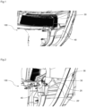
- FIG 1 shows an optical device for an automotive vehicle according to an embodiment of the present invention.
- the optical device 100 of the present invention comprises at least one light source 10 (as seen in Figure 3 ) configured to produce a light beam.
- the light beam produced by the light sources may be used for various lighting functions such as low beam light, high beam lights, turn indicator, parking/position lamp, tail/ stop lamp, day running lights (DRL), fog lamp and/ or signature lamp.
- the light sources 10 may be of amber and white color respectively to achieve the above said functions.
- the light sources 10 may be of red color to achieve stop lamp or tail lamp function, further, the light sources 10 may be adapted to achieve fog lamp function as well.
- the optical device 100 may comprise at least one light guide 20 configured to propagate said light beam.
- the at least one light guide 20 includes a light entry portion 22 arranged facing the at least one light source 10 to receive said light beam.
- the light beam that enters the at least one light guide 20 through the light entry portion 22 may be propagated towards a light exit portion (not shown) of the light guide 20 by means of multiple total internal reflection.
- the light beam exiting from said exit portion may be viewable from outside the optical device 100 to carry out the desired lighting function.
- Light guides are usually supported by a light guide support structure which may be further supported on a housing of the optical device.
- the support structure may also function as a mask that may be configured to mask a other components of the optical device.
- the optical device 100 further comprises at least one support structure 30 configured to support the at least one light guide 20.
- the support structure 30 may allow supporting the at least one light guide 20 with respect to the light sources 10.
- the light guide 20 are arranged such that optimal distance is maintained between the light sources and the at least one light guide 20. The optimal distance signifies the best possible position of the light guide with respect to the light sources so as to allow optimized or maximized amount of light beam produced by the light source 10 transmitted through the entry portion 22.
- the optical device 100 may comprise at least one cover 40 that is assembled with the at least one support structure 30 and may be configured to cover the light entry portion 22 of the at least one light guide 20.
- the at least one cover 40 is a physical structure or part that may be assembled over the specific portion of the light guide 20 so that the light guide may not be visible from outside the optical device 100.
- the at least one cover 40 and the at least one support structure 30 create a hinge 50 in an assembled state.
- a hinge may be defined as a mechanical bearing that is used to connect two solid part, typically allowing only a limited angle of rotation between them. The two parts connected by a hinge rotate relative to each other about a fixed axis of rotation.
- hinges have limited degree of freedom.
- tolerance are provided to allow limited movement between the mating or assembled parts.
- the limited movement may signify the movement between the parts in assembled state.
- the limited movement may enable ease of assembly and may prevent any damage to the parts.
- an ideal hinge only allows the rotation about a fixed axis of rotation, as mentioned above.
- tolerances are necessary, and the rotation or translation movements allowed by theses tolerances should not be considered as degrees of freedom.
- the hinge only has one rotation degree of freedom.
- hinges consists of three components namely, pin, knuckle and leaf and may be made of flexible material or of moving components.
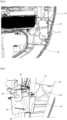
- the hinge 50 is configured to rotatably secure at least one cover 40 and the at least one support structure 30 around a hinge axis A-A' and further prevent translational movement of the at least one cover 40 with respect to the at least one support structure 30.
- At least one cover 40 comprises a first hinge portion 52 that is configured to be assembled relative to a second hinge portion 54 of the at least one the support structure 30.
- the first hinge portion 52 includes at least one supporting leg 521 having plurality of pins 522 that extend from the supporting leg 521 along the hinge axis A-A' and the second hinge portion 54 includes at least one slot 541 formed in the at least one support structure 30.
- the at least one supporting leg 521 may be connected to the at least one cover 40 and may extend away from the at least one cover 40.
- the plurality of pins 522 may be provided as a cantilever shaft projecting from the at least one supporting leg 521.
- the first hinge portion 52 may include two pins 522 that are extending away and opposite to each other along the hinge axis A-A'.
- the least one leg 521 may be flexible to enable easy assembly of the at least one cover 20 and the support structure 30.
- the first hinge portion 52 includes two supporting legs 521 that are connected to the at least one cover 20. Further, an end of the each of supporting legs 521 comprises a pin 522 that project from the supporting leg 521 along the hinge axis A-A'.
- the pins 522 are arranged facing away from each other, alternatively, the pins 522 can also be arranged facing towards each other as well.
- the pins 522 may be configured to mate with the at least one slot 541.
- the plurality of pins 522 when mated with the at least one slot 54 prevents translational movement of the at least one cover 40 but allows rotational motion of the at least one cover 40 around the hinge axis A-A'.
- the flexible nature of the supporting legs 521 allows the legs to be compressed during assembly so as to mate the pins 522 with the at least one slot 541. Once the pins 522 are mated with respective slots 541 the supporting legs are configured to return to its normal state.
- the hinge 50 comprises a hinge channel 56 extending tangentially from the hinge 50. The hinge channel 56 guides the first hinge portion 52 towards the second hinge portion 54 during assembly.
- the hinge channel may be designed such that the first hinge portion 52 gets compressed when entering the hinge channel 56. Further, the hinge channel 56 may end just before the at least one slot of the second hinge portion 54. The first hinge portion 52 when exiting said channel regains its shape and may be locked inside the at least one slot of the second hinge portion 54.
- the first hinge portion 52' comprises a pin 522' and a supporting leg 521' extending from said pin 522'.
- the supporting leg 521' may be attached to the at least one cover 40 and the pin 522' may be configured to mate with the second hinge portion 54.
- the supporting leg 521' may comprises a longitudinal slot 52a.
- the second portion 54 comprises at least one knuckle configured to mate with the pin 522'.
- the knuckle may include at least one arm 54a that may be configured to surround the pin 52' to secure the at least one cover 40 to the at least one support structure 30.
- a hinge 50 may be created between the at least one cover 20 and the supporting structure 30. Further, the at least one arm 54a of the knuckle may configured to pass through said longitudinal slot 52a to allow ease of assembly and prevent translational movement of the at least one cover 40.
- the at least one support structure 30 and the at least one cover 40 are integrally formed having a flexible portion configured to allow relative rotation between the at least one support structure 30 and at least one cover 40.
- the flexible portion may be made of a malleable material to provide flexibility to said flexible portion.
- the flexible portion may be made having a portion with a reduced or lower thickness, compared to at least one support structure 30 and at least one cover 40, to provide flexibility to said flexible portion. Further, the flexible portion may be made as below to accommodate the rotational motion of the cover 20 during assembly.
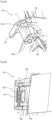
- Fig. 6 shows a preferred embodiment of the at least one cover 40.
- the at least one cover 40 includes at least one segment 42 adapted to surround a portion of the at least one light guide 20.
- the at least one segment 42 may be designed to match the profile and curvature of the at least one light guide 40.
- the light guide 20 may be supported on the supporting structure 30 by dedicated support means such.
- the at least one segment 42 may provide additional support to the at least one light guide inside optical device 100.
- the at least one guide portion 42 may also acts as shield to prevent light leakage from being visible from outside and also from leaking into other light guide. As seen in said Fig.
- At least one guide portion 42 is an integral rib structure formed substantially perpendicular to the planar surface of the at least one cover 40.
- the at least one segment 42 may be metalized or provided with reflective material so that the at least one segment 42 acts as an reflector to reflect any light beam back towards the at least one light guide 20.
- the optical device 100 comprises at least a first light guide 20, and a second light guide 20', configured to propagate light from at least two light sources 10.
- the two light guides 20, 20' may be associated with two light sources 10 such as amber color light source and white color light source for enabling turn indicator function and day running light function respectively.
- the first light guide 20 is associated with an amber color light source
- the second light guide 20' is associated with an white color light source, or opposite.
- both light guides may be associated each respectively with at least one amber color light source and one white color light source.
- the at least one cover 40 comprises at least two segments 42, 44 provided on opposite sides of at least one cover 40.
- the two light guides 20, 20' of the optical device 100 are surrounded by the respective segment 42, 44.
- the first light guide 20 may be surrounded by the segment 42 and the second light guide 20' may be surrounded by the segment 44.
- Alternate arrangements of the light guide 20, 20' with respect to the segments 42, 44 is also possible and may be provided in an alternate embodiment.
- the segments 42, 44 are on opposite sides of the at least one cover 40, the light from the first light guide 20 does not leak into the second light guide 20', and the light from the second light guide 20' does not leak into the first light guide 20.
- the at least one cover 40 as seen in Fig. 6 further comprises a clipping structure 46 configured secure the at least one cover 40 on the at least one support structure 30.
- the at least one support structure 30 comprises locking structure 58 (seen in Fig. 7 ) that may be configured to mate with the clipping structure 46.
- the clipping structure 46 and locking structure 58 may be designed to act as a press fit mechanism or a snap fit mechanism or similar connection means. Once the clipping structure is locked in the locking structure 58 the rotational motion of the cover can be arrested.
- the clipping structure 46 and locking structure 58 are designed such that they can not be separated easily.
- to meet the styling requirements of the optical device 100 may further comprise a bezel that may configured to hide a portion of the light guides.
- the assembly process comprises the steps of providing a first light guide 20 on the at least one support structure 30 of the optical device 100.
- the first light guide is provided such that a light entry portion 22 of the first light guide 20 is arranged facing a light source 10.
- the distance between the first light guide 20 and the light source 10 may be maintained such that optimized or maximized amount of light beam produced by the light source 10 is transmitted through the entry portion 22.
- at least one cover 40 may be provided on said support structure 30.
- the at least one cover 40 may be configured to form a hinge 50 with the at least one support structure 30.
- the hinge 50 comprises a first hinge portion 52 and a second hinge portion 54. Additionally, the first hinge portion 52 may be guided by hinge channel 56 towards the second hinge portion 54. Once the first hinge portion 52 is assembled with the second hinge portion 54, the at least one cover 40 may be rotated about a hinge axis A-A' to cover the light entry portion 22 of the first light guide 20.
- the assembly process comprises a step of providing a second light guide 20' over the at least one cover 40.
- the second light guide 20' may be provided on the opposite side of the at least one cover 40 as compared to the first light guide 20. Similar to the first light guide 20, light entry portion 22' of the second light guide 20' is arranged facing another light source 10.
- the at least one cover may be secured on the support using a clipping structure that are configured to mate with locking structures of the at least one support structure 30.
- a bezel may be provided for hiding a portion 22 of the first light guide 20 and the second light guide 20'.
- the cover 40 is provided with an additional cover element (not shown).
- the cover element may be connected to the cover 40 by means of an additional hinge element that enables the cover element to be rotated about the hinge element axis.
- the cover 40 is assembled to cover the first light guide 20 and the cover element is assembled to cover the second light guide 20' in the assembled state.
Landscapes
- Engineering & Computer Science (AREA)
- General Engineering & Computer Science (AREA)
- Non-Portable Lighting Devices Or Systems Thereof (AREA)
Priority Applications (1)
| Application Number | Priority Date | Filing Date | Title |
|---|---|---|---|
| EP21215781.2A EP4198380B1 (fr) | 2021-12-17 | 2021-12-17 | Dispositif optique pour un phare de véhicule automobile |
Applications Claiming Priority (1)
| Application Number | Priority Date | Filing Date | Title |
|---|---|---|---|
| EP21215781.2A EP4198380B1 (fr) | 2021-12-17 | 2021-12-17 | Dispositif optique pour un phare de véhicule automobile |
Publications (2)
| Publication Number | Publication Date |
|---|---|
| EP4198380A1 true EP4198380A1 (fr) | 2023-06-21 |
| EP4198380B1 EP4198380B1 (fr) | 2025-08-13 |
Family
ID=78957900
Family Applications (1)
| Application Number | Title | Priority Date | Filing Date |
|---|---|---|---|
| EP21215781.2A Active EP4198380B1 (fr) | 2021-12-17 | 2021-12-17 | Dispositif optique pour un phare de véhicule automobile |
Country Status (1)
| Country | Link |
|---|---|
| EP (1) | EP4198380B1 (fr) |
Citations (9)
| Publication number | Priority date | Publication date | Assignee | Title |
|---|---|---|---|---|
| US20030160754A1 (en) * | 2002-02-28 | 2003-08-28 | Palm, Inc. | Cover for electronic device |
| US20040257492A1 (en) * | 2003-04-30 | 2004-12-23 | Che-Kuei Mai | Backlight module |
| US20100000052A1 (en) * | 2008-07-03 | 2010-01-07 | Chia-Ko Chung | Slide hinge |
| US20120069592A1 (en) * | 2010-09-17 | 2012-03-22 | Koito Manufacturing Co., Ltd. | Vehicular lamp |
| KR20120078332A (ko) * | 2010-12-31 | 2012-07-10 | 엘지디스플레이 주식회사 | 액정 표시 장치 |
| CN106382586A (zh) * | 2016-08-29 | 2017-02-08 | 重庆长安汽车股份有限公司 | 一种车灯的防光导漏光结构 |
| CN107893966A (zh) * | 2017-11-14 | 2018-04-10 | 上海小糸车灯有限公司 | 一种防止光导漏光的灯具 |
| FR3066252A1 (fr) * | 2017-05-15 | 2018-11-16 | Automotive Lighting Rear Lamps France | Dispositif d'eclairage pour un feu de signalisation pour vehicule automobile, favorisant la propagation d'une plus grande quantite de lumiere dans un guide de lumiere |
| CN210511493U (zh) * | 2019-06-18 | 2020-05-12 | 法雷奥照明湖北技术中心有限公司 | 光学组件和用于车辆的车灯 |
-
2021
- 2021-12-17 EP EP21215781.2A patent/EP4198380B1/fr active Active
Patent Citations (9)
| Publication number | Priority date | Publication date | Assignee | Title |
|---|---|---|---|---|
| US20030160754A1 (en) * | 2002-02-28 | 2003-08-28 | Palm, Inc. | Cover for electronic device |
| US20040257492A1 (en) * | 2003-04-30 | 2004-12-23 | Che-Kuei Mai | Backlight module |
| US20100000052A1 (en) * | 2008-07-03 | 2010-01-07 | Chia-Ko Chung | Slide hinge |
| US20120069592A1 (en) * | 2010-09-17 | 2012-03-22 | Koito Manufacturing Co., Ltd. | Vehicular lamp |
| KR20120078332A (ko) * | 2010-12-31 | 2012-07-10 | 엘지디스플레이 주식회사 | 액정 표시 장치 |
| CN106382586A (zh) * | 2016-08-29 | 2017-02-08 | 重庆长安汽车股份有限公司 | 一种车灯的防光导漏光结构 |
| FR3066252A1 (fr) * | 2017-05-15 | 2018-11-16 | Automotive Lighting Rear Lamps France | Dispositif d'eclairage pour un feu de signalisation pour vehicule automobile, favorisant la propagation d'une plus grande quantite de lumiere dans un guide de lumiere |
| CN107893966A (zh) * | 2017-11-14 | 2018-04-10 | 上海小糸车灯有限公司 | 一种防止光导漏光的灯具 |
| CN210511493U (zh) * | 2019-06-18 | 2020-05-12 | 法雷奥照明湖北技术中心有限公司 | 光学组件和用于车辆的车灯 |
Also Published As
| Publication number | Publication date |
|---|---|
| EP4198380B1 (fr) | 2025-08-13 |
Similar Documents
| Publication | Publication Date | Title |
|---|---|---|
| US12422121B2 (en) | Optical element and light module of a motor vehicle equipped with such an optical element | |
| EP2253510B1 (fr) | Rétroviseur modulaire et son procédé d'assemblage | |
| US10443803B2 (en) | Lighting device with lightguide assembly which can be locked therein | |
| MX2014003270A (es) | Visera deslizable. | |
| EP2784338A2 (fr) | Structure de support d'articulation à rotule pour unité d'éclairage de véhicule | |
| EP4198380B1 (fr) | Dispositif optique pour un phare de véhicule automobile | |
| CN104832856B (zh) | 模块化车灯装置 | |
| US6817885B2 (en) | Arrangement for the electrical connection of a lamp | |
| JP3279911B2 (ja) | 乗り物用のヘッドランプ−ランプ−ユニット | |
| JP7515006B2 (ja) | 自動車投光器 | |
| EP4481268A1 (fr) | Dispositif optique pour véhicule automobile et procédé d'assemblage associé | |
| US11659897B2 (en) | Seat belt buckle and method for manufacturing a seat belt buckle | |
| EP4331946A1 (fr) | Volant de direction | |
| US12078326B2 (en) | Aircraft light with support board and kinematic coupling fixture and aircraft comprising the same | |
| US7314299B2 (en) | Vehicle lamp and method of manufacturing the vehicle lamp | |
| CN202419417U (zh) | 可调整光束角度的车灯 | |
| CN223869087U (zh) | 一种光学模组及车灯 | |
| CN108698491B (zh) | 遮阳板 | |
| CN219756170U (zh) | 一种挡光组件、灯具及车辆 | |
| CN115698586A (zh) | 用于机动车辆前照灯的部分远光灯模块的附接光学组件 | |
| EP4271933A1 (fr) | Dispositif réfléchissant, lampe de véhicule et véhicule | |
| JP6743673B2 (ja) | 車両用内装部品およびその取付け構造 | |
| CN221629558U (zh) | 固定装置、车灯和车辆 | |
| JP2005129287A (ja) | 室内照明灯 | |
| CN217273942U (zh) | 一种汽车前组合灯透镜组件 |
Legal Events
| Date | Code | Title | Description |
|---|---|---|---|
| PUAI | Public reference made under article 153(3) epc to a published international application that has entered the european phase |
Free format text: ORIGINAL CODE: 0009012 |
|
| STAA | Information on the status of an ep patent application or granted ep patent |
Free format text: STATUS: THE APPLICATION HAS BEEN PUBLISHED |
|
| AK | Designated contracting states |
Kind code of ref document: A1 Designated state(s): AL AT BE BG CH CY CZ DE DK EE ES FI FR GB GR HR HU IE IS IT LI LT LU LV MC MK MT NL NO PL PT RO RS SE SI SK SM TR |
|
| STAA | Information on the status of an ep patent application or granted ep patent |
Free format text: STATUS: REQUEST FOR EXAMINATION WAS MADE |
|
| 17P | Request for examination filed |
Effective date: 20231220 |
|
| RBV | Designated contracting states (corrected) |
Designated state(s): AL AT BE BG CH CY CZ DE DK EE ES FI FR GB GR HR HU IE IS IT LI LT LU LV MC MK MT NL NO PL PT RO RS SE SI SK SM TR |
|
| GRAP | Despatch of communication of intention to grant a patent |
Free format text: ORIGINAL CODE: EPIDOSNIGR1 |
|
| STAA | Information on the status of an ep patent application or granted ep patent |
Free format text: STATUS: GRANT OF PATENT IS INTENDED |
|
| INTG | Intention to grant announced |
Effective date: 20250303 |
|
| GRAS | Grant fee paid |
Free format text: ORIGINAL CODE: EPIDOSNIGR3 |
|
| GRAA | (expected) grant |
Free format text: ORIGINAL CODE: 0009210 |
|
| STAA | Information on the status of an ep patent application or granted ep patent |
Free format text: STATUS: THE PATENT HAS BEEN GRANTED |
|
| AK | Designated contracting states |
Kind code of ref document: B1 Designated state(s): AL AT BE BG CH CY CZ DE DK EE ES FI FR GB GR HR HU IE IS IT LI LT LU LV MC MK MT NL NO PL PT RO RS SE SI SK SM TR |
|
| REG | Reference to a national code |
Ref country code: GB Ref legal event code: FG4D |
|
| REG | Reference to a national code |
Ref country code: CH Ref legal event code: EP |
|
| REG | Reference to a national code |
Ref country code: DE Ref legal event code: R096 Ref document number: 602021036029 Country of ref document: DE |
|
| REG | Reference to a national code |
Ref country code: IE Ref legal event code: FG4D |
|
| REG | Reference to a national code |
Ref country code: NL Ref legal event code: MP Effective date: 20250813 |
|
| PG25 | Lapsed in a contracting state [announced via postgrant information from national office to epo] |
Ref country code: IS Free format text: LAPSE BECAUSE OF FAILURE TO SUBMIT A TRANSLATION OF THE DESCRIPTION OR TO PAY THE FEE WITHIN THE PRESCRIBED TIME-LIMIT Effective date: 20251213 |
|
| PG25 | Lapsed in a contracting state [announced via postgrant information from national office to epo] |
Ref country code: NO Free format text: LAPSE BECAUSE OF FAILURE TO SUBMIT A TRANSLATION OF THE DESCRIPTION OR TO PAY THE FEE WITHIN THE PRESCRIBED TIME-LIMIT Effective date: 20251113 |
|
| REG | Reference to a national code |
Ref country code: LT Ref legal event code: MG9D |
|
| PG25 | Lapsed in a contracting state [announced via postgrant information from national office to epo] |
Ref country code: PT Free format text: LAPSE BECAUSE OF FAILURE TO SUBMIT A TRANSLATION OF THE DESCRIPTION OR TO PAY THE FEE WITHIN THE PRESCRIBED TIME-LIMIT Effective date: 20251215 |
|
| PG25 | Lapsed in a contracting state [announced via postgrant information from national office to epo] |
Ref country code: FI Free format text: LAPSE BECAUSE OF FAILURE TO SUBMIT A TRANSLATION OF THE DESCRIPTION OR TO PAY THE FEE WITHIN THE PRESCRIBED TIME-LIMIT Effective date: 20250813 |
|
| PG25 | Lapsed in a contracting state [announced via postgrant information from national office to epo] |
Ref country code: HR Free format text: LAPSE BECAUSE OF FAILURE TO SUBMIT A TRANSLATION OF THE DESCRIPTION OR TO PAY THE FEE WITHIN THE PRESCRIBED TIME-LIMIT Effective date: 20250813 Ref country code: NL Free format text: LAPSE BECAUSE OF FAILURE TO SUBMIT A TRANSLATION OF THE DESCRIPTION OR TO PAY THE FEE WITHIN THE PRESCRIBED TIME-LIMIT Effective date: 20250813 |
|
| PGFP | Annual fee paid to national office [announced via postgrant information from national office to epo] |
Ref country code: FR Payment date: 20251230 Year of fee payment: 5 |
|
| PG25 | Lapsed in a contracting state [announced via postgrant information from national office to epo] |
Ref country code: GR Free format text: LAPSE BECAUSE OF FAILURE TO SUBMIT A TRANSLATION OF THE DESCRIPTION OR TO PAY THE FEE WITHIN THE PRESCRIBED TIME-LIMIT Effective date: 20251114 |
|
| PG25 | Lapsed in a contracting state [announced via postgrant information from national office to epo] |
Ref country code: SE Free format text: LAPSE BECAUSE OF FAILURE TO SUBMIT A TRANSLATION OF THE DESCRIPTION OR TO PAY THE FEE WITHIN THE PRESCRIBED TIME-LIMIT Effective date: 20250813 |
|
| PG25 | Lapsed in a contracting state [announced via postgrant information from national office to epo] |
Ref country code: LV Free format text: LAPSE BECAUSE OF FAILURE TO SUBMIT A TRANSLATION OF THE DESCRIPTION OR TO PAY THE FEE WITHIN THE PRESCRIBED TIME-LIMIT Effective date: 20250813 |
|
| PG25 | Lapsed in a contracting state [announced via postgrant information from national office to epo] |
Ref country code: PL Free format text: LAPSE BECAUSE OF FAILURE TO SUBMIT A TRANSLATION OF THE DESCRIPTION OR TO PAY THE FEE WITHIN THE PRESCRIBED TIME-LIMIT Effective date: 20250813 Ref country code: BG Free format text: LAPSE BECAUSE OF FAILURE TO SUBMIT A TRANSLATION OF THE DESCRIPTION OR TO PAY THE FEE WITHIN THE PRESCRIBED TIME-LIMIT Effective date: 20250813 |
|
| PG25 | Lapsed in a contracting state [announced via postgrant information from national office to epo] |
Ref country code: RS Free format text: LAPSE BECAUSE OF FAILURE TO SUBMIT A TRANSLATION OF THE DESCRIPTION OR TO PAY THE FEE WITHIN THE PRESCRIBED TIME-LIMIT Effective date: 20251113 |
|
| PG25 | Lapsed in a contracting state [announced via postgrant information from national office to epo] |
Ref country code: ES Free format text: LAPSE BECAUSE OF FAILURE TO SUBMIT A TRANSLATION OF THE DESCRIPTION OR TO PAY THE FEE WITHIN THE PRESCRIBED TIME-LIMIT Effective date: 20250813 |
|
| REG | Reference to a national code |
Ref country code: AT Ref legal event code: MK05 Ref document number: 1824984 Country of ref document: AT Kind code of ref document: T Effective date: 20250813 |
|
| PG25 | Lapsed in a contracting state [announced via postgrant information from national office to epo] |
Ref country code: RO Free format text: LAPSE BECAUSE OF FAILURE TO SUBMIT A TRANSLATION OF THE DESCRIPTION OR TO PAY THE FEE WITHIN THE PRESCRIBED TIME-LIMIT Effective date: 20250813 |
|
| PG25 | Lapsed in a contracting state [announced via postgrant information from national office to epo] |
Ref country code: SM Free format text: LAPSE BECAUSE OF FAILURE TO SUBMIT A TRANSLATION OF THE DESCRIPTION OR TO PAY THE FEE WITHIN THE PRESCRIBED TIME-LIMIT Effective date: 20250813 |
|
| PG25 | Lapsed in a contracting state [announced via postgrant information from national office to epo] |
Ref country code: DK Free format text: LAPSE BECAUSE OF FAILURE TO SUBMIT A TRANSLATION OF THE DESCRIPTION OR TO PAY THE FEE WITHIN THE PRESCRIBED TIME-LIMIT Effective date: 20250813 |
|
| PGFP | Annual fee paid to national office [announced via postgrant information from national office to epo] |
Ref country code: DE Payment date: 20251231 Year of fee payment: 5 |
|
| PG25 | Lapsed in a contracting state [announced via postgrant information from national office to epo] |
Ref country code: AT Free format text: LAPSE BECAUSE OF FAILURE TO SUBMIT A TRANSLATION OF THE DESCRIPTION OR TO PAY THE FEE WITHIN THE PRESCRIBED TIME-LIMIT Effective date: 20250813 |
|
| PG25 | Lapsed in a contracting state [announced via postgrant information from national office to epo] |
Ref country code: IT Free format text: LAPSE BECAUSE OF FAILURE TO SUBMIT A TRANSLATION OF THE DESCRIPTION OR TO PAY THE FEE WITHIN THE PRESCRIBED TIME-LIMIT Effective date: 20250813 |
|
| PG25 | Lapsed in a contracting state [announced via postgrant information from national office to epo] |
Ref country code: CZ Free format text: LAPSE BECAUSE OF FAILURE TO SUBMIT A TRANSLATION OF THE DESCRIPTION OR TO PAY THE FEE WITHIN THE PRESCRIBED TIME-LIMIT Effective date: 20250813 |
|
| PG25 | Lapsed in a contracting state [announced via postgrant information from national office to epo] |
Ref country code: EE Free format text: LAPSE BECAUSE OF FAILURE TO SUBMIT A TRANSLATION OF THE DESCRIPTION OR TO PAY THE FEE WITHIN THE PRESCRIBED TIME-LIMIT Effective date: 20250813 Ref country code: SK Free format text: LAPSE BECAUSE OF FAILURE TO SUBMIT A TRANSLATION OF THE DESCRIPTION OR TO PAY THE FEE WITHIN THE PRESCRIBED TIME-LIMIT Effective date: 20250813 |