EP4201866B1 - Treuil mécanique avec un commutateur mécanique pour terminer l'enroulement d'un câble sur le tambour du treuil - Google Patents
Treuil mécanique avec un commutateur mécanique pour terminer l'enroulement d'un câble sur le tambour du treuil Download PDFInfo
- Publication number
- EP4201866B1 EP4201866B1 EP22212377.0A EP22212377A EP4201866B1 EP 4201866 B1 EP4201866 B1 EP 4201866B1 EP 22212377 A EP22212377 A EP 22212377A EP 4201866 B1 EP4201866 B1 EP 4201866B1
- Authority
- EP
- European Patent Office
- Prior art keywords
- rope
- winch
- housing
- base plate
- plate
- Prior art date
- Legal status (The legal status is an assumption and is not a legal conclusion. Google has not performed a legal analysis and makes no representation as to the accuracy of the status listed.)
- Active
Links
Images


Classifications
-
- B—PERFORMING OPERATIONS; TRANSPORTING
- B66—HOISTING; LIFTING; HAULING
- B66D—CAPSTANS; WINCHES; TACKLES, e.g. PULLEY BLOCKS; HOISTS
- B66D1/00—Rope, cable, or chain winding mechanisms; Capstans
- B66D1/02—Driving gear
- B66D1/14—Power transmissions between power sources and drums or barrels
-
- B—PERFORMING OPERATIONS; TRANSPORTING
- B66—HOISTING; LIFTING; HAULING
- B66D—CAPSTANS; WINCHES; TACKLES, e.g. PULLEY BLOCKS; HOISTS
- B66D1/00—Rope, cable, or chain winding mechanisms; Capstans
- B66D1/02—Driving gear
- B66D1/14—Power transmissions between power sources and drums or barrels
- B66D1/16—Power transmissions between power sources and drums or barrels the drums or barrels being freely rotatable, e.g. having a clutch activated independently of a brake
-
- B—PERFORMING OPERATIONS; TRANSPORTING
- B66—HOISTING; LIFTING; HAULING
- B66D—CAPSTANS; WINCHES; TACKLES, e.g. PULLEY BLOCKS; HOISTS
- B66D1/00—Rope, cable, or chain winding mechanisms; Capstans
- B66D1/02—Driving gear
- B66D1/14—Power transmissions between power sources and drums or barrels
- B66D1/16—Power transmissions between power sources and drums or barrels the drums or barrels being freely rotatable, e.g. having a clutch activated independently of a brake
- B66D1/18—Power transmissions between power sources and drums or barrels the drums or barrels being freely rotatable, e.g. having a clutch activated independently of a brake and the power being transmitted from a continuously operating and irreversible prime mover, i.e. an internal combustion engine, e.g. on a motor vehicle or a portable winch
-
- B—PERFORMING OPERATIONS; TRANSPORTING
- B66—HOISTING; LIFTING; HAULING
- B66D—CAPSTANS; WINCHES; TACKLES, e.g. PULLEY BLOCKS; HOISTS
- B66D1/00—Rope, cable, or chain winding mechanisms; Capstans
- B66D1/54—Safety gear
- B66D1/56—Adaptations of limit switches
Definitions
- the present invention belongs to the field of mechanical engineering, more precisely to the field of forestry winches and safety devices for forestry winches.
- the invention relates to a mechanical winch with a mechanical switch for terminating winding of a rope on a drum of the winch.
- the brake When the first, green rope is pulled for activation of winding, the brake is automatically activated, which ensures that the brake belt slides along the winch drum, but it does not brake, because the drum is rotating in the direction of winding. Consequently, the drum is rotated, rope is wound onto it and the load is pulled towards the winch.
- the drum When the first rope for activation of winding is released with the load attached, the drum would rotate in the direction of unwinding of the rope, which is automatically prevented by the activated brake. This is enabled by an eccentric connected to the brake belt. Thus, the drum does not rotate and the rope is not winding anymore, which consequently holds the load steady.
- the second, red rope for deactivation of the brake has to be pulled, which via a special lever system releases the brake belt, thus allowing rotation of the drum, wherein the said lever system is connected to the brake belt so that the latter can be partly released using a handle.
- the brake can be released in two manners, i.e., proportionally with slight pulling so that the load is released in a step-wise manner, or completely with full movement to the position in which the brake is completely deactivated, thus locking the lever system and allowing the rope to freely unwind.
- the latter is used for example when pulling of the rope is needed during fixing of the load.
- the technical problem which is solved by the present invention, is a constructional design of a mechanism, which will reliably terminate the pulling function in a mechanical winch, wherein the mechanism has to enable easier return into the initial position, in which unwinding of the rope and consequent load pulling is enabled.
- a winch with a safety mechanism for switching off winding of a rope wherein an end switch for switching off rope winding is triggered with a pushing element, which is pushed into the end switch by a rotatably mounted washer on an accessory on a rope guide, when the accessory of an end piece due to winding of the pulling rope reaches the washer and pushes it into its final position.
- the mechanism may be installed in winches with electric, hydraulic or mechanic steering of winding and unwinding of the pulling rope.
- the present invention differs from this disclosure as the termination of winding is not purely mechanical.
- the solution of the stop switch described in patent JPS6050697 is adapted for a winch installed in a car. Termination of the drive of the pulling rope is achieved mechanically, wherein on one side a switching element rotatable around one axis is provided, said switching element can be pushed by the end part of the rope. Upon pressure of the end part of the rope on the switching element, a coupling for turning on and off the PTO shaft is moved, so that the winch terminates winding of the rope.
- This solution differs from the present invention in that termination of winding is achieved in a different manner, as the invention is adapted for a forestry winch, the drum of which is not driven by the PTO shaft.
- Patent application EP3042875 relates to a winch for forestry machines, agricultural machines and the like comprising a drum for winding and unwinding and unwinding a rope which can be connected to a load, and a rotary hydraulic motor whose shaft actuates the drum through a hydraulic distributor with manual control lever.
- the shaft of the hydraulic motor is coupled to the drum through a one-way engagement means which makes the shaft and drum mutually joined in rotation only in the set direction and corresponding to the winding of the rope on the drum.
- Said control lever is provided with a releasable engagement slide member of the rope when the latter is manually pulled to unwind from the drum, so as to displace the control lever to said unwinding position.
- the releasable engagement slid member and the decoupling is achieved in a different manner than in the present invention.
- Patent application US2016101969 discloses a drive train that includes a drive motor, a cable drum connected thereto, a reduction transmission arranged between the drive motor and the cable drum, a service brake provided between the drive motor and the reduction transmission and a safety brake.
- an automatic overrun disconnect means preferably a freewheel, is provided between the drive motor and the service brake, which is achieved through an electrically releasable coupling.
- the present invention does not use a freewheel to ensure winding or termination of winding and also does not use electrically controlled elements.
- Patent application US2019177136 describes a portable winch a safety switch that can be pulled by a cord to change the switch state to an off configuration and thereby kill or shut off the engine.
- a simple pull of a cord will actuate the switch and stop the system in an emergency stop fashion.
- a lanyard or cord is attached to a user switch, which is attached to the housing of the frame.
- a cap of the switch is moved from a coupled or on position to a decoupled or off position, which releases a limit switch allowing it to change state and thereby kill the engine.
- the switch is wired into the electrical system of the engine and thus, changing the state disrupts the electrical system of the engine, thereby shutting the engine off.
- This solution is not mechanical as the present invention, but relies on electrical connections to affect winding with the winch.
- the essence of the mechanical winch with a mechanical stop switch according to the invention is in that the mechanical stop switch has a Bowden inside which a wire rope is led, said wire rope being attached on one end to a pushing element installed at a orifice of a rope guide and on the other end to a switching mechanism, which upon contact of the end part of the rope with the pushing element moves from inactive to active position due to the translation through said wire rope.
- the orifice of the rope guide is provided with a spring-supported pushing element, which is preferably shaped as a washer or a plate with an opening for receiving the rope, which is with support elements connected to the inner part of the pushing element, or housing of the rope guide or the orifice, respectively,
- the Bowden, inside which the wire rope is led, is mounted on the pushing element or its inner part, respectively, wherein the wire rope is attached between the inner part and the outer washer or plate.
- the Bowden and the wire rope inside it are led to the switching mechanism and on the other end the Bowden is attached on the base plate or its accessory, while the wire rope is attached to the switching plate.
- the stop switch mechanism in the interior or the exterior of the winch comprises:
- At least three balls have to be provided, optimally five.
- suitable movable cylinders or pressure pins that operate in the same or similar manner as described balls can be used.
- the mechanical stop switch functions in the following way: the coupling is activated by pulling the green rope on the winch and consequently the base plate, which triggers operation of the winch (winding of the rope on the drum, i.e. pulling of the load.
- the mechanical force is transferred through the wire rope in the Bowden to the switching plate, which is rotated and releases momentum or locking force between the base plate and the housing or the handle of the base plate and the handle of the housing.
- the latter is connected to the coupling mechanism via a rod installed in a bearing of the housing, which consequently jumps to the zero position and terminates pulling with the winch.
- the base plate and the housing are returned to the zero-position due to activity of the spring.
- the balls or the restraining element move from the grooves in the switching plate to the grooves in the housing, which means that the positions of the base plate and the housing are locked again, so that the base plate and the housing are again movable together.
- the coupling mechanism is prepared for activation or pulling of a load with the winch.
- the return to the initial position, in which winding is again possible, can be done with another handle or a lever instead of springs, which is obvious to an expert in the field of machine components and the above description of the invention.
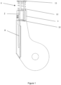
- Figure 1 shows an orifice 1 of the pulley, which is provided with a spring-supported pushing element shaped as a washer or a plate 11 with an opening for receiving the rope, which is with supporting elements 12 connected to an inner part 13 of the pushing element, housing of the guide or the orifice.
- Bowden B inside which the wire rope Z is installed, is mounted on the inner part 13 of the pushing element, while the wire rope is attached in the middle between the inner part 13 and the outer washer or the plate 11.
- the Bowden B and the wire rope Z are then led to the switching mechanism shown in figures 2 , 3 and 4.
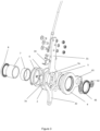
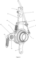
- Figure 4 shows an assembled switching mechanism, while figures 2 and 3 show intermediate bearings for installation on a winch axle, a distancing bush and distancing elements.
- the switching mechanism in the interior of the winch according to the preferred embodiment comprises:
- Figure 5 shows a cross-section of the switching mechanism, wherein the ball is between the base plate 3 and the housing 4, so that they are connected and pulling is enabled.
- the switching plate 2 has the groove, which is upon rotation of the switching plate 2 due to impact of the end part of the rope to the pushing element 11 moved in such a manner to align with holes of the base plate 3, which moves the balls 5 between the base plate 3 and the switching plate 2 and terminates winding.
- pulling the green rope does not activate in pulling, as the elements are disengaged.
- the elements For return into the initial state in which activation is enabled, the elements have to be returned into their initial state, i.e. both plate 3 and housing 4 have to be connected.
- the spring attached to the frame and the leg 32 of the plate 3 ensures the first step, while the plate 3 is pulled into its initial position by pulling the winch red rope. This initial position is needed for any new working cycle (load pulling) that has been terminated using the described switching mechanism.
Landscapes
- Engineering & Computer Science (AREA)
- Mechanical Engineering (AREA)
- Chemical & Material Sciences (AREA)
- Combustion & Propulsion (AREA)
- Storing, Repeated Paying-Out, And Re-Storing Of Elongated Articles (AREA)
- Transmission Devices (AREA)
Claims (4)
- Un treuil mécanique avec un commutateur mécanique pour terminer l'enroulement d'un câble sur le tambour du treuil, qui comprend une poulie comprenant un guide pour le câble avec un orifice (1) pourvu d'un élément de poussée monté sur ressort (13), de préférence ayant la forme d'une rondelle ou d'une plaque (11) munie d'un trou pour recevoir le câble, ladite rondelle ou plaque (11) étant raccordée avec des éléments de support (12) à une partie interne de l'élément de poussée (13), le boîtier du guide ou l'orifice (1), où un Bowden (B) à l'intérieur duquel un câble métallique (Z) est installé, est monté sur l'élément de poussée ou sa partie interne (13), respectivement, tandis que le câble métallique (Z) est fixé entre la partie interne (13) et une rondelle ou une plaque externe, et où le Bowden (B) et le câble métallique sont dirigés vers un mécanisme de commutation à l'intérieur ou à l'extérieur du treuil, ledit mécanisme de commutation comprenant :- une plaque de base (3) ayant la forme d'une rondelle avec deux pieds (31, 32) dirigés dans des directions opposées, où le pied supérieur (31) est connecté au mécanisme d'activation, c.-à-d., le câble vert pour l'activation de l'enroulement du câble sur le tambour du treuil,- une plaque de commutation (2), à laquelle le câble métallique (Z) est raccordé par des vis avec écrous, où le câble métallique est dirigé par le biais d'un accessoire (33) et, ledit câble métallique étant acheminé à l'intérieur du Bowden (B),- un boîtier (4) ayant la forme d'une rondelle avec un pied (41), qui est approximativement perpendiculaire ou à tout autre angle par rapport à un axe des deux pieds (31, 32) de la plaque de base (3), où ledit pied (41) de boîtier est pourvu d'un trou (42) destiné à un roulement pour raccorder l'accouplement de l'entraînement du tambour et une oreille pour le montage d'un ressort (43),- deux ressorts pour le mouvement de retour de la plaque de base (3) et du boîtier (4) depuis leur position finale à leur position initiale (neutre), oùoù les plaques (2, 3) et le boîtier (4) sont installés sur l'axe principal du treuil, sur lequel le tambour du treuil est monté en utilisant des éléments d'écartement appropriés (6, 7) et des roulements (8), et∘ le premier ressort est monté sur le pied de boîtier (4) et un châssis de treuil, et∘ le second ressort est monté sur un support fixé sur un pied de la plaque de base (3) et à la plaque de commutation (2),- entre la plaque de base (3) et le boîtier (4), au moins un élément limiteur (5) est disposé dans des rainures ou des trous adaptés (3a, 4a),- la plaque de commutation (2) est pourvue de rainures ou de trous (2a) pour recevoir ledit élément limiteur (5), et est disposée de façon à pivoter lors du mouvement du câble métallique (Z) à l'intérieur du Bowden (B), ce qui provoque l'alignement des rainures (2a) avec les trous (3a) sur la plaque de base (3), ce qui provoque le mouvement de l'élément limiteur (5), et le désengagement de la connexion entre la plaque de base (3) et le boîtier (4)où lors de l'impact de la partie finale du câble sur l'élément de poussée, la force mécanique est convertie par le biais du câble métallique dans le Bowden vers la plaque de commutation, qui est disposée de façon à pivoter et par conséquent à libérer la quantité de mouvement ou la force de verrouillage entre la plaque de base (3) et le boîtier (4) ou le pied de la plaque de base (3) et le pied du boîtier (4), ce qui se fait par le biais d'une tige installée dans un roulement du boîtier (4) connecté au mécanisme d'accouplement, qui est disposé de façon à se déplacer dans une position neutre et termine la traction par le treuil ; etoù la plaque est disposée de façon à retourner à sa position initiale en utilisant :- un ressort pour le mouvement de retour et la traction du câble rouge du treuil, ou- une manivelle ou un levier supplémentaire, qui est disposé pour la rotation de la plaque de commutation,permettant ainsi à l'élément limiteur d'être déplacé depuis les rainures de la plaque de commutation (2) dans les rainures du boîtier (4), verrouillant ainsi les positions de la plaque de base (3) et du boîtier (4).
- Le treuil mécanique avec un commutateur mécanique pour terminer l'enroulement du câble sur le tambour du treuil selon la revendication 1, où le Bowden (B) est fixé de façon complémentaire sur le pied supérieur plus long (31) de la plaque de base (3) ou une fixation (33) montée dessus.
- Le treuil mécanique avec un commutateur mécanique pour terminer l'enroulement du câble sur le tambour du treuil selon l'une quelconque des revendications précédentes, où l'élément limiteur (5) est sélectionné dans le groupe constitué de boules, cylindres ou chevilles.
- Le treuil mécanique avec un commutateur mécanique pour terminer l'enroulement du câble sur le tambour du treuil selon l'une quelconque des revendications précédentes, où l'élément limiteur (5) est conçu comme se composant d'au moins trois boules, de préférence cinq.
Priority Applications (2)
| Application Number | Priority Date | Filing Date | Title |
|---|---|---|---|
| SI202230056T SI4201866T1 (sl) | 2021-12-20 | 2022-12-08 | Mehanski vitel z mehanskim stikalom za prekinitev navijanja vrvi na boben vitla |
| HRP20241430TT HRP20241430T1 (hr) | 2021-12-20 | 2022-12-08 | Mehaničko vitlo s mehaničkim prekidačem za okončanje namatanja sajle na bubanj vitla |
Applications Claiming Priority (1)
| Application Number | Priority Date | Filing Date | Title |
|---|---|---|---|
| SI202100228A SI26289A (sl) | 2021-12-20 | 2021-12-20 | Mehanski vitel z mehanskim stikalom za prekinitev navijanja vrvi na boben vitla |
Publications (2)
| Publication Number | Publication Date |
|---|---|
| EP4201866A1 EP4201866A1 (fr) | 2023-06-28 |
| EP4201866B1 true EP4201866B1 (fr) | 2024-07-24 |
Family
ID=85158899
Family Applications (1)
| Application Number | Title | Priority Date | Filing Date |
|---|---|---|---|
| EP22212377.0A Active EP4201866B1 (fr) | 2021-12-20 | 2022-12-08 | Treuil mécanique avec un commutateur mécanique pour terminer l'enroulement d'un câble sur le tambour du treuil |
Country Status (4)
| Country | Link |
|---|---|
| EP (1) | EP4201866B1 (fr) |
| HR (1) | HRP20241430T1 (fr) |
| PL (1) | PL4201866T3 (fr) |
| SI (2) | SI26289A (fr) |
Family Cites Families (5)
| Publication number | Priority date | Publication date | Assignee | Title |
|---|---|---|---|---|
| JP6050697B2 (ja) | 2013-02-12 | 2016-12-21 | 株式会社岡村製作所 | 段積み段ばらし装置 |
| DE102013209361A1 (de) * | 2013-05-21 | 2014-11-27 | M.A.T. Malmedie Antriebstechnik Gmbh | Antriebsstrang für Hubwerke |
| EP3042875B1 (fr) * | 2015-01-08 | 2017-12-27 | Ricca Andrea & C. S.n.c. | Treuil pour la foresterie, machines agricoles et similaires |
| SI24997A (sl) | 2015-05-22 | 2016-11-30 | PIĹ EK - VITLI KRPAN, d.o.o. | Vitel z varnostnim mehanizmom za izklop navijanja vrvi |
| US10781087B2 (en) * | 2017-09-28 | 2020-09-22 | Mark S. Soderberg | Trailer mounted capstan winch |
-
2021
- 2021-12-20 SI SI202100228A patent/SI26289A/sl not_active IP Right Cessation
-
2022
- 2022-12-08 SI SI202230056T patent/SI4201866T1/sl unknown
- 2022-12-08 HR HRP20241430TT patent/HRP20241430T1/hr unknown
- 2022-12-08 EP EP22212377.0A patent/EP4201866B1/fr active Active
- 2022-12-08 PL PL22212377.0T patent/PL4201866T3/pl unknown
Also Published As
| Publication number | Publication date |
|---|---|
| SI26289A (sl) | 2023-06-30 |
| SI4201866T1 (sl) | 2025-01-31 |
| HRP20241430T1 (hr) | 2024-12-20 |
| EP4201866A1 (fr) | 2023-06-28 |
| PL4201866T3 (pl) | 2024-12-16 |
Similar Documents
| Publication | Publication Date | Title |
|---|---|---|
| EP3287407B1 (fr) | Régulateur de survitesse d'ascenseur | |
| JP2019202891A (ja) | リフト機構のシステム配置およびシステム配置を作動させる方法 | |
| EP3326952B1 (fr) | Dispositif de déclenchement à distance, ensemble de régulateur de survitesse et ascenseur | |
| EP0878434B1 (fr) | Palan de levage à commande manuelle | |
| KR960005022B1 (ko) | 레버식 권상견인기 | |
| EP0433922B1 (fr) | Mécanisme à frein pour appareil de stockage et de déstockage | |
| IT9019538A1 (it) | Dispositivo di sicurezza per un apparecchio di sollevamento o simile | |
| EP4201866A1 (fr) | Treuil mécanique avec un commutateur mécanique pour terminer l'enroulement d'un câble sur le tambour du treuil | |
| US2809804A (en) | Universal scaffolding machine | |
| US5570872A (en) | Free-rotation control apparatus of hoist and traction machine | |
| US5159996A (en) | Wrap band safety brake | |
| TWI899241B (zh) | 旋轉鎖定裝置、手搖吊車以及起吊機械 | |
| EP3929143A1 (fr) | Un treuil mécanique disposant d'un mécanisme de contrle avec une sécurité améliorée | |
| EP3842201B1 (fr) | Un fendeur a bois avec treuil mecanique et methode d'operation | |
| WO2020050768A1 (fr) | Mécanisme pour un dispositif de sécurité pour une cabine d'ascenseur, dispositif de sécurité pour la protection contre un déplacement de cabine involontaire d'une cabine d'ascenseur et agencement de sécurité pour un système d'ascenseur | |
| EP3988494A1 (fr) | Treuil forestier doté d'un commutateur d'arrêt mécanique | |
| CN2892804Y (zh) | 起重机常闭常开双功能制动器装置 | |
| KR100398962B1 (ko) | 인양기의 추락방지장치 | |
| JPS5841280B2 (ja) | ウインチノ カフカジドウブレ−キソウチ | |
| JPH07172779A (ja) | レバー式巻上牽引機 | |
| US12151919B2 (en) | Winch clutch and winch thereof | |
| JPH02270792A (ja) | エレベータのターニングハンドル機構 | |
| KR20250036549A (ko) | 특장차 부품 연결용 링커 장치 | |
| JP2023553713A (ja) | レバーホイスト | |
| KR20030085922A (ko) | 낚시용 릴 |
Legal Events
| Date | Code | Title | Description |
|---|---|---|---|
| PUAI | Public reference made under article 153(3) epc to a published international application that has entered the european phase |
Free format text: ORIGINAL CODE: 0009012 |
|
| STAA | Information on the status of an ep patent application or granted ep patent |
Free format text: STATUS: THE APPLICATION HAS BEEN PUBLISHED |
|
| AK | Designated contracting states |
Kind code of ref document: A1 Designated state(s): AL AT BE BG CH CY CZ DE DK EE ES FI FR GB GR HR HU IE IS IT LI LT LU LV MC ME MK MT NL NO PL PT RO RS SE SI SK SM TR |
|
| P01 | Opt-out of the competence of the unified patent court (upc) registered |
Effective date: 20230707 |
|
| STAA | Information on the status of an ep patent application or granted ep patent |
Free format text: STATUS: REQUEST FOR EXAMINATION WAS MADE |
|
| 17P | Request for examination filed |
Effective date: 20231122 |
|
| RBV | Designated contracting states (corrected) |
Designated state(s): AL AT BE BG CH CY CZ DE DK EE ES FI FR GB GR HR HU IE IS IT LI LT LU LV MC ME MK MT NL NO PL PT RO RS SE SI SK SM TR |
|
| GRAP | Despatch of communication of intention to grant a patent |
Free format text: ORIGINAL CODE: EPIDOSNIGR1 |
|
| STAA | Information on the status of an ep patent application or granted ep patent |
Free format text: STATUS: GRANT OF PATENT IS INTENDED |
|
| INTG | Intention to grant announced |
Effective date: 20240415 |
|
| GRAS | Grant fee paid |
Free format text: ORIGINAL CODE: EPIDOSNIGR3 |
|
| GRAA | (expected) grant |
Free format text: ORIGINAL CODE: 0009210 |
|
| STAA | Information on the status of an ep patent application or granted ep patent |
Free format text: STATUS: THE PATENT HAS BEEN GRANTED |
|
| AK | Designated contracting states |
Kind code of ref document: B1 Designated state(s): AL AT BE BG CH CY CZ DE DK EE ES FI FR GB GR HR HU IE IS IT LI LT LU LV MC ME MK MT NL NO PL PT RO RS SE SI SK SM TR |
|
| REG | Reference to a national code |
Ref country code: GB Ref legal event code: FG4D |
|
| REG | Reference to a national code |
Ref country code: CH Ref legal event code: EP |
|
| REG | Reference to a national code |
Ref country code: IE Ref legal event code: FG4D Ref country code: DE Ref legal event code: R096 Ref document number: 602022004821 Country of ref document: DE |
|
| REG | Reference to a national code |
Ref country code: LT Ref legal event code: MG9D |
|
| REG | Reference to a national code |
Ref country code: NL Ref legal event code: MP Effective date: 20240724 |
|
| PG25 | Lapsed in a contracting state [announced via postgrant information from national office to epo] |
Ref country code: PT Free format text: LAPSE BECAUSE OF FAILURE TO SUBMIT A TRANSLATION OF THE DESCRIPTION OR TO PAY THE FEE WITHIN THE PRESCRIBED TIME-LIMIT Effective date: 20241125 |
|
| PG25 | Lapsed in a contracting state [announced via postgrant information from national office to epo] |
Ref country code: NL Free format text: LAPSE BECAUSE OF FAILURE TO SUBMIT A TRANSLATION OF THE DESCRIPTION OR TO PAY THE FEE WITHIN THE PRESCRIBED TIME-LIMIT Effective date: 20240724 |
|
| REG | Reference to a national code |
Ref country code: SK Ref legal event code: T3 Ref document number: E 45194 Country of ref document: SK |
|
| REG | Reference to a national code |
Ref country code: HR Ref legal event code: T1PR Ref document number: P20241430 Country of ref document: HR |
|
| PG25 | Lapsed in a contracting state [announced via postgrant information from national office to epo] |
Ref country code: PT Free format text: LAPSE BECAUSE OF FAILURE TO SUBMIT A TRANSLATION OF THE DESCRIPTION OR TO PAY THE FEE WITHIN THE PRESCRIBED TIME-LIMIT Effective date: 20241125 Ref country code: NL Free format text: LAPSE BECAUSE OF FAILURE TO SUBMIT A TRANSLATION OF THE DESCRIPTION OR TO PAY THE FEE WITHIN THE PRESCRIBED TIME-LIMIT Effective date: 20240724 |
|
| PG25 | Lapsed in a contracting state [announced via postgrant information from national office to epo] |
Ref country code: NO Free format text: LAPSE BECAUSE OF FAILURE TO SUBMIT A TRANSLATION OF THE DESCRIPTION OR TO PAY THE FEE WITHIN THE PRESCRIBED TIME-LIMIT Effective date: 20241024 |
|
| PG25 | Lapsed in a contracting state [announced via postgrant information from national office to epo] |
Ref country code: FI Free format text: LAPSE BECAUSE OF FAILURE TO SUBMIT A TRANSLATION OF THE DESCRIPTION OR TO PAY THE FEE WITHIN THE PRESCRIBED TIME-LIMIT Effective date: 20240724 Ref country code: GR Free format text: LAPSE BECAUSE OF FAILURE TO SUBMIT A TRANSLATION OF THE DESCRIPTION OR TO PAY THE FEE WITHIN THE PRESCRIBED TIME-LIMIT Effective date: 20241025 |
|
| REG | Reference to a national code |
Ref country code: HR Ref legal event code: ODRP Ref document number: P20241430 Country of ref document: HR Payment date: 20241204 Year of fee payment: 3 |
|
| PG25 | Lapsed in a contracting state [announced via postgrant information from national office to epo] |
Ref country code: BG Free format text: LAPSE BECAUSE OF FAILURE TO SUBMIT A TRANSLATION OF THE DESCRIPTION OR TO PAY THE FEE WITHIN THE PRESCRIBED TIME-LIMIT Effective date: 20240724 |
|
| PG25 | Lapsed in a contracting state [announced via postgrant information from national office to epo] |
Ref country code: LV Free format text: LAPSE BECAUSE OF FAILURE TO SUBMIT A TRANSLATION OF THE DESCRIPTION OR TO PAY THE FEE WITHIN THE PRESCRIBED TIME-LIMIT Effective date: 20240724 |
|
| PG25 | Lapsed in a contracting state [announced via postgrant information from national office to epo] |
Ref country code: IS Free format text: LAPSE BECAUSE OF FAILURE TO SUBMIT A TRANSLATION OF THE DESCRIPTION OR TO PAY THE FEE WITHIN THE PRESCRIBED TIME-LIMIT Effective date: 20241124 |
|
| PG25 | Lapsed in a contracting state [announced via postgrant information from national office to epo] |
Ref country code: RS Free format text: LAPSE BECAUSE OF FAILURE TO SUBMIT A TRANSLATION OF THE DESCRIPTION OR TO PAY THE FEE WITHIN THE PRESCRIBED TIME-LIMIT Effective date: 20241024 Ref country code: ES Free format text: LAPSE BECAUSE OF FAILURE TO SUBMIT A TRANSLATION OF THE DESCRIPTION OR TO PAY THE FEE WITHIN THE PRESCRIBED TIME-LIMIT Effective date: 20240724 |
|
| PG25 | Lapsed in a contracting state [announced via postgrant information from national office to epo] |
Ref country code: RS Free format text: LAPSE BECAUSE OF FAILURE TO SUBMIT A TRANSLATION OF THE DESCRIPTION OR TO PAY THE FEE WITHIN THE PRESCRIBED TIME-LIMIT Effective date: 20241024 Ref country code: NO Free format text: LAPSE BECAUSE OF FAILURE TO SUBMIT A TRANSLATION OF THE DESCRIPTION OR TO PAY THE FEE WITHIN THE PRESCRIBED TIME-LIMIT Effective date: 20241024 Ref country code: LV Free format text: LAPSE BECAUSE OF FAILURE TO SUBMIT A TRANSLATION OF THE DESCRIPTION OR TO PAY THE FEE WITHIN THE PRESCRIBED TIME-LIMIT Effective date: 20240724 Ref country code: IS Free format text: LAPSE BECAUSE OF FAILURE TO SUBMIT A TRANSLATION OF THE DESCRIPTION OR TO PAY THE FEE WITHIN THE PRESCRIBED TIME-LIMIT Effective date: 20241124 Ref country code: GR Free format text: LAPSE BECAUSE OF FAILURE TO SUBMIT A TRANSLATION OF THE DESCRIPTION OR TO PAY THE FEE WITHIN THE PRESCRIBED TIME-LIMIT Effective date: 20241025 Ref country code: FI Free format text: LAPSE BECAUSE OF FAILURE TO SUBMIT A TRANSLATION OF THE DESCRIPTION OR TO PAY THE FEE WITHIN THE PRESCRIBED TIME-LIMIT Effective date: 20240724 Ref country code: ES Free format text: LAPSE BECAUSE OF FAILURE TO SUBMIT A TRANSLATION OF THE DESCRIPTION OR TO PAY THE FEE WITHIN THE PRESCRIBED TIME-LIMIT Effective date: 20240724 Ref country code: BG Free format text: LAPSE BECAUSE OF FAILURE TO SUBMIT A TRANSLATION OF THE DESCRIPTION OR TO PAY THE FEE WITHIN THE PRESCRIBED TIME-LIMIT Effective date: 20240724 |
|
| PG25 | Lapsed in a contracting state [announced via postgrant information from national office to epo] |
Ref country code: SM Free format text: LAPSE BECAUSE OF FAILURE TO SUBMIT A TRANSLATION OF THE DESCRIPTION OR TO PAY THE FEE WITHIN THE PRESCRIBED TIME-LIMIT Effective date: 20240724 Ref country code: DK Free format text: LAPSE BECAUSE OF FAILURE TO SUBMIT A TRANSLATION OF THE DESCRIPTION OR TO PAY THE FEE WITHIN THE PRESCRIBED TIME-LIMIT Effective date: 20240724 |
|
| PG25 | Lapsed in a contracting state [announced via postgrant information from national office to epo] |
Ref country code: EE Free format text: LAPSE BECAUSE OF FAILURE TO SUBMIT A TRANSLATION OF THE DESCRIPTION OR TO PAY THE FEE WITHIN THE PRESCRIBED TIME-LIMIT Effective date: 20240724 |
|
| REG | Reference to a national code |
Ref country code: DE Ref legal event code: R097 Ref document number: 602022004821 Country of ref document: DE |
|
| PLBE | No opposition filed within time limit |
Free format text: ORIGINAL CODE: 0009261 |
|
| STAA | Information on the status of an ep patent application or granted ep patent |
Free format text: STATUS: NO OPPOSITION FILED WITHIN TIME LIMIT |
|
| 26N | No opposition filed |
Effective date: 20250425 |
|
| PG25 | Lapsed in a contracting state [announced via postgrant information from national office to epo] |
Ref country code: MC Free format text: LAPSE BECAUSE OF FAILURE TO SUBMIT A TRANSLATION OF THE DESCRIPTION OR TO PAY THE FEE WITHIN THE PRESCRIBED TIME-LIMIT Effective date: 20240724 |
|
| PG25 | Lapsed in a contracting state [announced via postgrant information from national office to epo] |
Ref country code: SE Free format text: LAPSE BECAUSE OF FAILURE TO SUBMIT A TRANSLATION OF THE DESCRIPTION OR TO PAY THE FEE WITHIN THE PRESCRIBED TIME-LIMIT Effective date: 20240724 |
|
| REG | Reference to a national code |
Ref country code: BE Ref legal event code: MM Effective date: 20241231 |
|
| REG | Reference to a national code |
Ref country code: AT Ref legal event code: UEP Ref document number: 1706160 Country of ref document: AT Kind code of ref document: T Effective date: 20240724 |
|
| PG25 | Lapsed in a contracting state [announced via postgrant information from national office to epo] |
Ref country code: BE Free format text: LAPSE BECAUSE OF NON-PAYMENT OF DUE FEES Effective date: 20241231 |
|
| PG25 | Lapsed in a contracting state [announced via postgrant information from national office to epo] |
Ref country code: IE Free format text: LAPSE BECAUSE OF NON-PAYMENT OF DUE FEES Effective date: 20241208 |
|
| PGFP | Annual fee paid to national office [announced via postgrant information from national office to epo] |
Ref country code: AT Payment date: 20260113 Year of fee payment: 4 |
|
| PGFP | Annual fee paid to national office [announced via postgrant information from national office to epo] |
Ref country code: LU Payment date: 20251205 Year of fee payment: 4 Ref country code: HR Payment date: 20251208 Year of fee payment: 4 Ref country code: FR Payment date: 20251222 Year of fee payment: 4 |
|
| REG | Reference to a national code |
Ref country code: HR Ref legal event code: ODRP Ref document number: P20241430 Country of ref document: HR Payment date: 20251208 Year of fee payment: 4 |
|
| PGFP | Annual fee paid to national office [announced via postgrant information from national office to epo] |
Ref country code: CZ Payment date: 20251208 Year of fee payment: 4 |
|
| PGFP | Annual fee paid to national office [announced via postgrant information from national office to epo] |
Ref country code: PL Payment date: 20251208 Year of fee payment: 4 |
|
| PGFP | Annual fee paid to national office [announced via postgrant information from national office to epo] |
Ref country code: RO Payment date: 20251208 Year of fee payment: 4 Ref country code: SK Payment date: 20251205 Year of fee payment: 4 |
|
| PGFP | Annual fee paid to national office [announced via postgrant information from national office to epo] |
Ref country code: SI Payment date: 20251205 Year of fee payment: 4 |
|
| PGFP | Annual fee paid to national office [announced via postgrant information from national office to epo] |
Ref country code: DE Payment date: 20251215 Year of fee payment: 4 |
|
| PGFP | Annual fee paid to national office [announced via postgrant information from national office to epo] |
Ref country code: IT Payment date: 20251231 Year of fee payment: 4 |
|
| PG25 | Lapsed in a contracting state [announced via postgrant information from national office to epo] |
Ref country code: CY Free format text: LAPSE BECAUSE OF FAILURE TO SUBMIT A TRANSLATION OF THE DESCRIPTION OR TO PAY THE FEE WITHIN THE PRESCRIBED TIME-LIMIT Effective date: 20240724 |