EP4202122A1 - Carreau à emboîtement - Google Patents
Carreau à emboîtement Download PDFInfo
- Publication number
- EP4202122A1 EP4202122A1 EP22216526.8A EP22216526A EP4202122A1 EP 4202122 A1 EP4202122 A1 EP 4202122A1 EP 22216526 A EP22216526 A EP 22216526A EP 4202122 A1 EP4202122 A1 EP 4202122A1
- Authority
- EP
- European Patent Office
- Prior art keywords
- tile
- coupler
- male
- female
- tiles
- Prior art date
- Legal status (The legal status is an assumption and is not a legal conclusion. Google has not performed a legal analysis and makes no representation as to the accuracy of the status listed.)
- Granted
Links
Images





Classifications
-
- E—FIXED CONSTRUCTIONS
- E01—CONSTRUCTION OF ROADS, RAILWAYS, OR BRIDGES
- E01C—CONSTRUCTION OF, OR SURFACES FOR, ROADS, SPORTS GROUNDS, OR THE LIKE; MACHINES OR AUXILIARY TOOLS FOR CONSTRUCTION OR REPAIR
- E01C13/00—Pavings or foundations specially adapted for playgrounds or sports grounds; Drainage, irrigation or heating of sports grounds
- E01C13/04—Pavings made of prefabricated single units
- E01C13/045—Pavings made of prefabricated single units the prefabricated single units consisting of or including bitumen, rubber or plastics
-
- E—FIXED CONSTRUCTIONS
- E04—BUILDING
- E04F—FINISHING WORK ON BUILDINGS, e.g. STAIRS, FLOORS
- E04F15/00—Flooring
- E04F15/02—Flooring or floor layers composed of a number of similar elements
-
- E—FIXED CONSTRUCTIONS
- E01—CONSTRUCTION OF ROADS, RAILWAYS, OR BRIDGES
- E01C—CONSTRUCTION OF, OR SURFACES FOR, ROADS, SPORTS GROUNDS, OR THE LIKE; MACHINES OR AUXILIARY TOOLS FOR CONSTRUCTION OR REPAIR
- E01C5/00—Pavings made of prefabricated single units
- E01C5/20—Pavings made of prefabricated single units made of units of plastics, e.g. concrete with plastics, linoleum
-
- E—FIXED CONSTRUCTIONS
- E01—CONSTRUCTION OF ROADS, RAILWAYS, OR BRIDGES
- E01C—CONSTRUCTION OF, OR SURFACES FOR, ROADS, SPORTS GROUNDS, OR THE LIKE; MACHINES OR AUXILIARY TOOLS FOR CONSTRUCTION OR REPAIR
- E01C2201/00—Paving elements
- E01C2201/12—Paving elements vertically interlocking
-
- E—FIXED CONSTRUCTIONS
- E01—CONSTRUCTION OF ROADS, RAILWAYS, OR BRIDGES
- E01C—CONSTRUCTION OF, OR SURFACES FOR, ROADS, SPORTS GROUNDS, OR THE LIKE; MACHINES OR AUXILIARY TOOLS FOR CONSTRUCTION OR REPAIR
- E01C2201/00—Paving elements
- E01C2201/20—Drainage details
-
- E—FIXED CONSTRUCTIONS
- E01—CONSTRUCTION OF ROADS, RAILWAYS, OR BRIDGES
- E01C—CONSTRUCTION OF, OR SURFACES FOR, ROADS, SPORTS GROUNDS, OR THE LIKE; MACHINES OR AUXILIARY TOOLS FOR CONSTRUCTION OR REPAIR
- E01C2201/00—Paving elements
- E01C2201/20—Drainage details
- E01C2201/202—Horizontal drainage channels
- E01C2201/207—Horizontal drainage channels channels on the bottom
-
- E—FIXED CONSTRUCTIONS
- E04—BUILDING
- E04F—FINISHING WORK ON BUILDINGS, e.g. STAIRS, FLOORS
- E04F2201/00—Joining sheets or plates or panels
- E04F2201/09—Puzzle-type connections for interlocking male and female panel edge-parts
- E04F2201/095—Puzzle-type connections for interlocking male and female panel edge-parts with both connection parts, i.e. male and female connection parts alternating on one edge
Definitions
- the disclosure relates generally to the field of floor tiles. More specifically, the disclosure relates to interlocking floor tiles and systems and methods incorporating interlocking floor tiles.
- Interlocking floor tiles are known in the art. Such tiles employ various interlocking mechanisms. Often, the interlocking mechanisms result in a rigid connection between tiles, which prevent the tiles from flexing, at least to some degree. Further, such tiles may also require a prepared surface that is generally even. If the surface has too much variation, the locking mechanisms may not work as intended, or at all.
- interlocking tile that allows for deformation or shifting in response to forces applied to the tile surface, e.g., from walking or driving on the surface.
- an interlocking tile in one embodiment, includes a top surface, a bottom surface, and marginal faces disposed along a perimeter of the top surface.
- the tile also includes at least one male coupler disposed on a first marginal face and at least one female coupler extending from the bottom surface and disposed on a second marginal face.
- the at least one female coupler includes an arm, which has a first notch for engaging with a corresponding male coupler of an adjacent tile at a first position, and a second notch for engaging with the corresponding male coupler of the adjacent tile at a second position.
- an interlocking tile system includes a first tile comprising a top surface, marginal faces disposed along at least a portion of a perimeter of the top surface, a male coupler disposed on a first marginal face, and a female coupler disposed on a second marginal face.
- the female coupler includes an arm, the arm comprising a first notch for engaging with a corresponding male coupler of an adjacent tile at a first position, and a second notch for engaging with the corresponding male coupler of the adjacent tile at a second position.
- a method of adjoining interlocking floor tiles on an uneven surface comprises providing a plurality of floor tiles.
- Each tile has a male coupler extending from a first marginal face of the floor tile that includes an aperture.
- Each tile further includes a female coupler disposed along a second marginal face of the floor tile.
- the female coupler includes an arm having a proximal and a distal end and a plurality of notches located generally near the distal end.
- the method further includes positioning a first tile of the plurality of tiles generally adjacent a second tile of the plurality of tiles such that the male coupler of the first tile is generally adjacent the female coupler of the second tile.
- the first and second tiles are interlocked by inserting the arm of the female coupler of the second tile into the aperture of the male coupler of the first tile such that one of the plurality of notches of the arm of the female coupler of the second tile engages with the male coupler of the first tile.
- FIGs. 1 and 2 show an embodiment of a floor tile 100 which has a top surface 110 ( FIG. 1 ), an optional bottom surface 120 ( FIG. 2 ), and marginal faces 130 which may extend at least partially along a perimeter of the top surface 110.
- Top surface 110 may be generally even and regular.
- voids 111 may defined in the top surface 110, e.g., to allow for drainage, as shown in FIG. 4 .
- Bottom surface 120 includes a support structure 122, which supports the tile 100 above the surface.
- the support structure 122 may include portions 123b that extend from the bottom surface 120 provide strength to the tile top surface 110. Additionally, the support structure 122 may include portions 123a that extend beyond the portions 123b. The portions 123a contact the ground surface when the tile 100 is in an installed configuration.
- passages 124 may be defined within the support structure 122.
- the passages 124 may improve the drainage underneath the floor tile 100. Passages 124 may also facilitate additional aspects of the tile 100, for example, allowing for tubing or wiring to pass under the floor tile 100.
- the tubing or wiring may be contained within passages 124.
- the passages 124 may span the entire width of bottom surface 120, in lieu of any support structure 122, e.g., as is the case with channel tiles 200, described in greater detail below
- marginal faces 103 extend around the perimeter of the tile 100, and may be generally perpendicular to the top surface 110. In some embodiments the marginal face 130 may be offset from top surface 110 at a non-perpendicular angle. Marginal faces 130 extend past the bottom surface 120 of the floor tile 100 and may form a part of the support structure 122. In some embodiments, marginal face 130 may be of variable height, as shown in FIG. 5 .
- tile 100 has a generally rectangular shape, although it will be understood by those of skill in the art that tile 100 may resemble a variety of shapes, such as generally triangular, trapezoidal, pentagonal, hexagonal, and octagonal.
- the tile 100 is configured to couple to other tiles 100 and/or tile components.
- FIG. 3 illustrates a tile system showing a first tile 100a coupled to a second tile 100b and tile channels 200a and 200b.
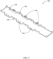
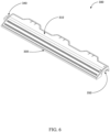
- a tile channel 200 is illustrated in FIGs. 4 and 5 and is substantially similar to floor tile 100, except as specifically noted and/or shown, or as would be inherent.
- reference numbers from 200 to 299 may be used to indicate elements corresponding to those discussed above numbered from 100 to 199 (e.g., top surface 210 corresponds generally to the top surface 110, faces 230 correspond generally to the respective faces 130, et cetera), though with any noted, shown, or inherent deviations.
- tile channel 200 may have a bottom surface 220 which is generally planar.
- Tile channel 200 may vary from tile 100 in that tile channel 200 may not include a supporting structure or any portion which extends outward from the bottom surface 220. This may be desired in order to create a larger passage underneath the tile channel 200 for wiring, piping, drainage, or any other system which may be installed below tile channel 200.
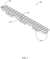
- edge piece 300 may include a top surface 310 which includes a generally planar portion and a portion 330 which is angularly offset from horizontal.
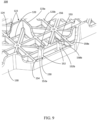
- floor tiles 100 and tile channels 200 may have at least one male coupler 140 ( FIG. 8 ) and at least one female coupler 150 ( FIG. 9 ).
- floor tiles 100 and tile channels 200 may have a plurality of male couplers 140 and female couplers 150.
- the male couplers 140 may be disposed along two adjacent sides 130 of a tile 100, with female couplers 150 being disposed along the remaining two adjacent sides 130.
- male couplers 140 may be disposed along two opposing sides 130 of a tile 100, with female couplers 150 being disposed along the remaining two opposing sides 130.
- each side may have male couplers 150 or female couplers 140.
- the tile channels 200 may include one or more male couplers 240 disposed along a first long edge, with one or more female couplers 250 disposed along an opposing second long edge. Short edges of the tile channels 200 may or may not include couplers 240 and/or 250.
- each edge piece 300 may include at least one male coupler 340 or at least one female coupler 350 along a long edge (or along a straight edge, if it's a corner edge piece). Accordingly, edge pieces 300 may be particularly configured to attach to a side of a tile having either a male coupler 340 or a female coupler 350.
- each short edge of the edge pieces 300 may additionally include a male coupler 340 or a female coupler 350, and preferably may include a male coupler 340 on one short edge and a female coupler 350 on the opposing short edge, to facilitate coupling of the edge piece along the perimeter of the tiles 100.
- a male coupler 140 is illustrated with a tile 100.
- Male couplers 140 may extend outward from marginal face 130 of tile 100.
- the male couplers 140 may extend perpendicularly from the marginal face 130, although it may be advantageous for the couplers 140 to extend at a non-perpendicular angle from the marginal face 130.
- the male couplers 140 do not extend the entire height of the marginal face 130. However, it will be understood by those of skill in the art that the male couplers 140 may extend along the entire height of the marginal face 130.
- Each male coupler 140 may include a central portion and at least one aperture 142 for connecting with a corresponding female coupler 150.
- each male coupler 140 has a plurality of apertures 142.
- a male coupler 240, 340 on a tile channel 200 or an edge piece 300, respectively is substantially similar to the male coupler 140 described herein.
- tile channels 200 FIGs. 4 and 5
- edge pieces 300 FIGs. 6 and 7
- a female coupler 150 is illustrated with a tile 100. It shall be understood that a female coupler 150 on a tile channel 200 or an edge piece 300 is substantially similar to that described herein.
- the female couplers 150 are configured to be complimentary to the male couplers 140, such that floor tiles 100 may be coupled together to form a tile system.
- Female couplers 150 may include at least one arm 152 extending from bottom surface 120 of the floor tile 100, and preferably two opposing arms 152a and 152b. Each arm 152 has a proximal end 154, a distal end 156, and at least one notch 158 on an inside face of an elbow 153 of the arm 152.
- the arms 152 may have two notches 158a and 158b.
- the notices 158a and 158b may not be colinear.
- the first notch 158a may be generally inwardly offset as compared to the second notch 152b.
- the double notch may allow for floor tiles 100 to be installed over an uneven surface so that if a tile 100 is slightly elevated compared to an adjacent tile 100, the first notch 158a may engage with a corresponding male coupler 140 of the adjacent tile 100. If the neighboring tiles 100 are on the same level, the second notch 158b may engage with the corresponding male coupler 140 of the adjacent tile 100.
- adjacent tiles 100 may be adjoined on different horizontal planes depending on which notch 158a or 158b is engaged between respective male and female couplers 140 and 150.
- the arms 152 have two notches, it will be understood by those of skill in the art that arms 152 may have any number of notches 158, and may therefore be able to engage with male coupler 140 at a plurality of heights.
- the arms 152 may be positioned inside of the marginal face 130. Additionally, as shown in FIG. 1 , the top surface 110 may extend over the female coupler 150. This may allow the respective marginal faces 130 of adjacent tiles 100 to more closely abut.
- FIG. 11 illustrates a spring tab 160 disposed along the marginal face 130 of a floor tile 100.
- the spring tab 160 may have an exterior face 162 and a slot 166.
- floor tile 100 has a plurality of spring tabs 160 disposed along the marginal face 130.
- Spring tabs 160 create a gap between adjacent tiles 100. The creation of a gap between tiles 100 may allow for a small amount of deformation during impacts. Furthermore, the gap created by spring tabs 160 may allow for expansion or contraction of the floor tiles 100 when subject to extreme temperatures, thereby minimizing the likelihood of component failure.
- the exterior face 162 of spring tab 160 is generally planar and is substantially parallel to the marginal face 130.
- the exterior face 160 may not be generally planar, and instead may be concave, convex, or angled.
- the spring tabs 160 may be constructed from the same material as the other components of floor tile 100. However, it may be beneficial to construct the spring tabs 160 from a different material than that of the rest of floor tile 100. For example, a more flexible material, in conjunction with various shapes of the spring tabs 160, may provide a more desirable level of impact dispersion and/or temporary deformation.
- tile channels 200 may optionally additionally include spring tabs 160.
- FIG. 11 illustrates another embodiment of a floor tile 400 that is substantially similar to floor tile 100, except as specifically noted and/or shown, or as would be inherent. Further, those skilled in the art will appreciate that the embodiment 100 (and thus the embodiment 400) may be modified in various ways, such as through incorporating all or part of any of the described embodiments, for example. For uniformity and brevity, reference numbers from 400 to 499 may be used to indicate elements corresponding to those discussed above numbered from 100 to 199 (e.g., top surface 410 corresponds generally to the top surface 110, faces 430 correspond generally to the respective faces 130, et cetera), though with any noted, shown, or inherent deviations.
- top surface 410 corresponds generally to the top surface 110
- faces 430 correspond generally to the respective faces 130, et cetera
- Tile 400 may have at least one projection 412 having a proximal end 414 and a distal end 416 and extending from the top surface 410.
- tile 400 may have a plurality of projections 412 extending from the top surface 410. Projections 412 may provide increased resistance against shifting of artificial turf or any other material which may be placed upon the top surface 410. Even without a material atop the tile 400, the projections 412 may friction to the top surface 410 to prevent slippage, e.g., of a person moving atop the tile 400 or a vehicle driving atop the tile 400.
- projections 412 have a general triangular prism shape. However, it will be understood by those of skill in the art that projections 412 may be any shape, including rectangular, conical, cylindrical, pyramid, et cetera.
- the at least one projection 412 may form part of a coupling mechanism with any surface material that may be applied to the tile 100.
- a corresponding recess may be provided in the turf backing or other surface material.
- the projections 412 may greatly reduce unwanted shifting of the material atop the tile 400.
- the projections 412 may reduce or even eliminate the need for adhesives to be applied between the tile 400 and any surface material, which may reduce the time required for installing a tile and surface material systema and further allow for easier maintenance of the system.
- the projections 412 may be molded (e.g., via injection molding, co-injection molding, overmolding, multi-material injection molding, etc.) as part of the floor tile 400.
- the projections 412 may be molded via a removable insert which may be added or removed to the tile mold during the molding process. This may be beneficial, as it allows for a variation in design or functionality of the tiles without the need for bespoke molds.
Landscapes
- Engineering & Computer Science (AREA)
- Architecture (AREA)
- Civil Engineering (AREA)
- Structural Engineering (AREA)
- Floor Finish (AREA)
Applications Claiming Priority (1)
| Application Number | Priority Date | Filing Date | Title |
|---|---|---|---|
| US17/646,034 US12000154B2 (en) | 2021-12-27 | 2021-12-27 | Interlocking tile |
Publications (3)
| Publication Number | Publication Date |
|---|---|
| EP4202122A1 true EP4202122A1 (fr) | 2023-06-28 |
| EP4202122C0 EP4202122C0 (fr) | 2025-02-12 |
| EP4202122B1 EP4202122B1 (fr) | 2025-02-12 |
Family
ID=84604006
Family Applications (1)
| Application Number | Title | Priority Date | Filing Date |
|---|---|---|---|
| EP22216526.8A Active EP4202122B1 (fr) | 2021-12-27 | 2022-12-23 | Carreau à emboîtement |
Country Status (3)
| Country | Link |
|---|---|
| US (1) | US12000154B2 (fr) |
| EP (1) | EP4202122B1 (fr) |
| ES (1) | ES3026883T3 (fr) |
Families Citing this family (4)
| Publication number | Priority date | Publication date | Assignee | Title |
|---|---|---|---|---|
| US20240360632A1 (en) * | 2021-08-31 | 2024-10-31 | Plastic Safety Systems, Inc. | Temporary walkway system with modular tiles interlocking in three-dimensions |
| USD1074983S1 (en) * | 2021-09-01 | 2025-05-13 | Hymie Ades | Modular radiator and air conditioner cover tile |
| CN216822705U (zh) * | 2022-03-01 | 2022-06-28 | 苏州恒瑞达家用地垫有限公司 | 一种隐藏式拼接地垫 |
| CN116607718A (zh) * | 2023-05-26 | 2023-08-18 | 常州市豪优杰智能科技有限公司 | 一种干法铺装瓷砖结构及铺装方法 |
Citations (5)
| Publication number | Priority date | Publication date | Assignee | Title |
|---|---|---|---|---|
| US20080072514A1 (en) * | 2006-09-27 | 2008-03-27 | Barlow David R | Interlocking floor system |
| US8266857B2 (en) * | 2006-09-27 | 2012-09-18 | David Barlow R | Interlocking floor system with barbs for retaining covering |
| US9267244B2 (en) * | 2013-03-15 | 2016-02-23 | Wholesale Turf Supply Llc | Synthetic grass tile system and method |
| CN110644722A (zh) * | 2019-10-16 | 2020-01-03 | 常州泰辉橡塑新材料有限公司 | 运动地板及其制备方法 |
| US10941577B1 (en) * | 2019-10-09 | 2021-03-09 | Ch3 Solutions, Llc | Anti-theft apparatus and systems and methods for using same |
Family Cites Families (28)
| Publication number | Priority date | Publication date | Assignee | Title |
|---|---|---|---|---|
| US3735988A (en) | 1971-06-17 | 1973-05-29 | D J Palmer | Practice putting surface |
| CA1191304A (fr) * | 1983-02-23 | 1985-08-06 | Richard A. Morrison | Tapis couvre-sol modulaire a lisiere d'assemblage |
| US4902540A (en) | 1988-11-17 | 1990-02-20 | Martino Louis D | Modular athletic turf |
| US5076534A (en) * | 1990-09-17 | 1991-12-31 | Bramec Corporation | Base support for air conditioners or the like |
| US5323575A (en) | 1993-06-01 | 1994-06-28 | Yeh Tzung Jzng | Tile and mounting mat assembly |
| ATE193572T1 (de) * | 1994-12-19 | 2000-06-15 | Sportfoerderung Peter Kueng Ag | Elastisches kunststoffelement zum bilden eines bodenbelages |
| US5904021A (en) * | 1997-07-29 | 1999-05-18 | Fisher; Kirk R. | Modular flooring recreational use |
| US7273642B2 (en) | 2000-09-01 | 2007-09-25 | Fieldturf Tarkett Inc. | Modular synthetic grass turf assembly |
| CA2435460A1 (fr) * | 2001-01-29 | 2002-08-08 | Spider Court, Inc. | Carreaux modulaires et systeme de pose de carrelage |
| US6802159B1 (en) | 2002-05-31 | 2004-10-12 | Snap Lock Industries, Inc. | Roll-up floor tile system and the method |
| CA2577590A1 (fr) | 2004-08-20 | 2006-04-27 | Azulindus Y Marti, S.A. | Revetement demontable pour surfaces |
| US20080092473A1 (en) | 2004-10-05 | 2008-04-24 | Heyns Albertus N | Substrate Element, Modular Tiling Element, System Of Interlocking Mechanisms And Method Of Tiling |
| US8407951B2 (en) | 2004-10-06 | 2013-04-02 | Connor Sport Court International, Llc | Modular synthetic floor tile configured for enhanced performance |
| CN101087918B (zh) * | 2004-12-24 | 2010-06-16 | 孙昌燮 | 草皮护垫和护垫组件 |
| US7730696B2 (en) | 2005-05-23 | 2010-06-08 | Scott Reynolds | Method of making a stone wall |
| US7587865B2 (en) | 2005-06-02 | 2009-09-15 | Moller Jr Jorgen J | Modular floor tile with multi level support system |
| US7571572B2 (en) | 2005-06-02 | 2009-08-11 | Moller Jr Jorgen J | Modular floor tile system with sliding lock |
| US20070059481A1 (en) * | 2005-09-15 | 2007-03-15 | Lin Chien J | Floor pads |
| US7930865B2 (en) | 2006-09-27 | 2011-04-26 | Barlow David R | Method of installing an interlocking floor system |
| US7955025B2 (en) | 2007-10-02 | 2011-06-07 | Fieldturf Tarkett Inc. | Tile for synthetic grass system |
| US8141314B2 (en) | 2009-05-26 | 2012-03-27 | Signature Fencing and Flooring Systems, Inc. | Expansion joint for modular flooring system |
| CN102448352B (zh) | 2009-06-01 | 2014-07-09 | 坦德斯地板公司 | 利用非随机安装技术的随机织物块安装 |
| US8782989B2 (en) * | 2009-06-11 | 2014-07-22 | Comc, Llc | Narrow lined modular flooring assemblies |
| US8919054B2 (en) * | 2012-05-04 | 2014-12-30 | Mmi Andersen Company, Llc | Layered floor tile connectable to form an area mat that resists delamination from scuffing |
| US8833007B2 (en) * | 2012-05-04 | 2014-09-16 | MMI Anderson Company, LLC | Modular floor tile connectable with another modular floor tile to form an area mat that resists separation during use |
| US9133628B2 (en) * | 2013-09-19 | 2015-09-15 | Snapsports Company | Multi-stage shock absorbing modular floor tile apparatus |
| US20160129299A1 (en) * | 2014-11-11 | 2016-05-12 | Howard Hancock Newman | Hinged interlocking tiles |
| US10914081B2 (en) * | 2017-12-15 | 2021-02-09 | Wearwell, Llc | Interlocking modular mat with sponge insert |
-
2021
- 2021-12-27 US US17/646,034 patent/US12000154B2/en active Active
-
2022
- 2022-12-23 ES ES22216526T patent/ES3026883T3/es active Active
- 2022-12-23 EP EP22216526.8A patent/EP4202122B1/fr active Active
Patent Citations (5)
| Publication number | Priority date | Publication date | Assignee | Title |
|---|---|---|---|---|
| US20080072514A1 (en) * | 2006-09-27 | 2008-03-27 | Barlow David R | Interlocking floor system |
| US8266857B2 (en) * | 2006-09-27 | 2012-09-18 | David Barlow R | Interlocking floor system with barbs for retaining covering |
| US9267244B2 (en) * | 2013-03-15 | 2016-02-23 | Wholesale Turf Supply Llc | Synthetic grass tile system and method |
| US10941577B1 (en) * | 2019-10-09 | 2021-03-09 | Ch3 Solutions, Llc | Anti-theft apparatus and systems and methods for using same |
| CN110644722A (zh) * | 2019-10-16 | 2020-01-03 | 常州泰辉橡塑新材料有限公司 | 运动地板及其制备方法 |
Also Published As
| Publication number | Publication date |
|---|---|
| US20230203822A1 (en) | 2023-06-29 |
| EP4202122C0 (fr) | 2025-02-12 |
| US12000154B2 (en) | 2024-06-04 |
| ES3026883T3 (en) | 2025-06-12 |
| EP4202122B1 (fr) | 2025-02-12 |
Similar Documents
| Publication | Publication Date | Title |
|---|---|---|
| EP4202122A1 (fr) | Carreau à emboîtement | |
| EP1948883B1 (fr) | Système conçu pour poser des carreaux, ensemble carreau et élément raccord utilisé dans ce système, procédé de pose de carreaux, et procédé de réparation d'un plancher de carreaux | |
| US8863473B2 (en) | Interconnectable panel system and method of panel interconnection | |
| US7958681B2 (en) | Modular floor tile with nonslip insert system | |
| US7908802B2 (en) | System for constructing tread surfaces | |
| US20090282769A1 (en) | Modular floor tile system with sliding lock | |
| US10145124B2 (en) | Modular panels for making an installable / removable temporary floor and method for making said floor | |
| CN102046899A (zh) | 镶板、尤其是地板镶板 | |
| EP0781364B1 (fr) | Panneau de revetement pour structures de terre | |
| US20200173119A1 (en) | Fastening system | |
| US12553191B2 (en) | Foundation system | |
| GB2602732A (en) | Foundation system | |
| JPH0653604U (ja) | 敷板の連結装置 | |
| HK1003901B (en) | Facing panel for earth structures | |
| JPH09273293A (ja) | 床仕上げ材およびその施工方法 |
Legal Events
| Date | Code | Title | Description |
|---|---|---|---|
| PUAI | Public reference made under article 153(3) epc to a published international application that has entered the european phase |
Free format text: ORIGINAL CODE: 0009012 |
|
| STAA | Information on the status of an ep patent application or granted ep patent |
Free format text: STATUS: THE APPLICATION HAS BEEN PUBLISHED |
|
| AK | Designated contracting states |
Kind code of ref document: A1 Designated state(s): AL AT BE BG CH CY CZ DE DK EE ES FI FR GB GR HR HU IE IS IT LI LT LU LV MC ME MK MT NL NO PL PT RO RS SE SI SK SM TR |
|
| STAA | Information on the status of an ep patent application or granted ep patent |
Free format text: STATUS: REQUEST FOR EXAMINATION WAS MADE |
|
| 17P | Request for examination filed |
Effective date: 20231227 |
|
| RBV | Designated contracting states (corrected) |
Designated state(s): AL AT BE BG CH CY CZ DE DK EE ES FI FR GB GR HR HU IE IS IT LI LT LU LV MC ME MK MT NL NO PL PT RO RS SE SI SK SM TR |
|
| GRAP | Despatch of communication of intention to grant a patent |
Free format text: ORIGINAL CODE: EPIDOSNIGR1 |
|
| STAA | Information on the status of an ep patent application or granted ep patent |
Free format text: STATUS: GRANT OF PATENT IS INTENDED |
|
| INTG | Intention to grant announced |
Effective date: 20240827 |
|
| GRAS | Grant fee paid |
Free format text: ORIGINAL CODE: EPIDOSNIGR3 |
|
| GRAA | (expected) grant |
Free format text: ORIGINAL CODE: 0009210 |
|
| STAA | Information on the status of an ep patent application or granted ep patent |
Free format text: STATUS: THE PATENT HAS BEEN GRANTED |
|
| AK | Designated contracting states |
Kind code of ref document: B1 Designated state(s): AL AT BE BG CH CY CZ DE DK EE ES FI FR GB GR HR HU IE IS IT LI LT LU LV MC ME MK MT NL NO PL PT RO RS SE SI SK SM TR |
|
| REG | Reference to a national code |
Ref country code: GB Ref legal event code: FG4D |
|
| REG | Reference to a national code |
Ref country code: CH Ref legal event code: EP |
|
| REG | Reference to a national code |
Ref country code: DE Ref legal event code: R096 Ref document number: 602022010478 Country of ref document: DE |
|
| REG | Reference to a national code |
Ref country code: IE Ref legal event code: FG4D |
|
| U01 | Request for unitary effect filed |
Effective date: 20250310 |
|
| U07 | Unitary effect registered |
Designated state(s): AT BE BG DE DK EE FI FR IT LT LU LV MT NL PT RO SE SI Effective date: 20250317 |
|
| REG | Reference to a national code |
Ref country code: ES Ref legal event code: FG2A Ref document number: 3026883 Country of ref document: ES Kind code of ref document: T3 Effective date: 20250612 |
|
| PG25 | Lapsed in a contracting state [announced via postgrant information from national office to epo] |
Ref country code: RS Free format text: LAPSE BECAUSE OF FAILURE TO SUBMIT A TRANSLATION OF THE DESCRIPTION OR TO PAY THE FEE WITHIN THE PRESCRIBED TIME-LIMIT Effective date: 20250512 |
|
| PG25 | Lapsed in a contracting state [announced via postgrant information from national office to epo] |
Ref country code: PL Free format text: LAPSE BECAUSE OF FAILURE TO SUBMIT A TRANSLATION OF THE DESCRIPTION OR TO PAY THE FEE WITHIN THE PRESCRIBED TIME-LIMIT Effective date: 20250212 |
|
| PG25 | Lapsed in a contracting state [announced via postgrant information from national office to epo] |
Ref country code: NO Free format text: LAPSE BECAUSE OF FAILURE TO SUBMIT A TRANSLATION OF THE DESCRIPTION OR TO PAY THE FEE WITHIN THE PRESCRIBED TIME-LIMIT Effective date: 20250512 Ref country code: IS Free format text: LAPSE BECAUSE OF FAILURE TO SUBMIT A TRANSLATION OF THE DESCRIPTION OR TO PAY THE FEE WITHIN THE PRESCRIBED TIME-LIMIT Effective date: 20250612 |
|
| PG25 | Lapsed in a contracting state [announced via postgrant information from national office to epo] |
Ref country code: HR Free format text: LAPSE BECAUSE OF FAILURE TO SUBMIT A TRANSLATION OF THE DESCRIPTION OR TO PAY THE FEE WITHIN THE PRESCRIBED TIME-LIMIT Effective date: 20250212 |
|
| PG25 | Lapsed in a contracting state [announced via postgrant information from national office to epo] |
Ref country code: GR Free format text: LAPSE BECAUSE OF FAILURE TO SUBMIT A TRANSLATION OF THE DESCRIPTION OR TO PAY THE FEE WITHIN THE PRESCRIBED TIME-LIMIT Effective date: 20250513 |
|
| PG25 | Lapsed in a contracting state [announced via postgrant information from national office to epo] |
Ref country code: SM Free format text: LAPSE BECAUSE OF FAILURE TO SUBMIT A TRANSLATION OF THE DESCRIPTION OR TO PAY THE FEE WITHIN THE PRESCRIBED TIME-LIMIT Effective date: 20250212 |
|
| PG25 | Lapsed in a contracting state [announced via postgrant information from national office to epo] |
Ref country code: CZ Free format text: LAPSE BECAUSE OF FAILURE TO SUBMIT A TRANSLATION OF THE DESCRIPTION OR TO PAY THE FEE WITHIN THE PRESCRIBED TIME-LIMIT Effective date: 20250212 |
|
| PG25 | Lapsed in a contracting state [announced via postgrant information from national office to epo] |
Ref country code: SK Free format text: LAPSE BECAUSE OF FAILURE TO SUBMIT A TRANSLATION OF THE DESCRIPTION OR TO PAY THE FEE WITHIN THE PRESCRIBED TIME-LIMIT Effective date: 20250212 |
|
| PLBE | No opposition filed within time limit |
Free format text: ORIGINAL CODE: 0009261 |
|
| STAA | Information on the status of an ep patent application or granted ep patent |
Free format text: STATUS: NO OPPOSITION FILED WITHIN TIME LIMIT |
|
| 26N | No opposition filed |
Effective date: 20251113 |
|
| U20 | Renewal fee for the european patent with unitary effect paid |
Year of fee payment: 4 Effective date: 20251218 |
|
| PGFP | Annual fee paid to national office [announced via postgrant information from national office to epo] |
Ref country code: ES Payment date: 20260102 Year of fee payment: 4 |