EP4202169A1 - Battant de fenêtre ou de porte et fenêtre ou porte comprenant ledit battant - Google Patents
Battant de fenêtre ou de porte et fenêtre ou porte comprenant ledit battant Download PDFInfo
- Publication number
- EP4202169A1 EP4202169A1 EP22214471.9A EP22214471A EP4202169A1 EP 4202169 A1 EP4202169 A1 EP 4202169A1 EP 22214471 A EP22214471 A EP 22214471A EP 4202169 A1 EP4202169 A1 EP 4202169A1
- Authority
- EP
- European Patent Office
- Prior art keywords
- window
- door leaf
- glazing
- door
- rebate
- Prior art date
- Legal status (The legal status is an assumption and is not a legal conclusion. Google has not performed a legal analysis and makes no representation as to the accuracy of the status listed.)
- Granted
Links
Images


Classifications
-
- E—FIXED CONSTRUCTIONS
- E06—DOORS, WINDOWS, SHUTTERS, OR ROLLER BLINDS IN GENERAL; LADDERS
- E06B—FIXED OR MOVABLE CLOSURES FOR OPENINGS IN BUILDINGS, VEHICLES, FENCES OR LIKE ENCLOSURES IN GENERAL, e.g. DOORS, WINDOWS, BLINDS, GATES
- E06B3/00—Window sashes, door leaves, or like elements for closing wall or like openings; Layout of fixed or moving closures, e.g. windows in wall or like openings; Features of rigidly-mounted outer frames relating to the mounting of wing frames
- E06B3/54—Fixing of glass panes or like plates
- E06B3/58—Fixing of glass panes or like plates by means of borders, cleats, or the like
- E06B3/5807—Fixing of glass panes or like plates by means of borders, cleats, or the like not adjustable
- E06B3/5821—Fixing of glass panes or like plates by means of borders, cleats, or the like not adjustable hooked on or in the frame member, fixed by clips or otherwise elastically fixed
-
- E—FIXED CONSTRUCTIONS
- E06—DOORS, WINDOWS, SHUTTERS, OR ROLLER BLINDS IN GENERAL; LADDERS
- E06B—FIXED OR MOVABLE CLOSURES FOR OPENINGS IN BUILDINGS, VEHICLES, FENCES OR LIKE ENCLOSURES IN GENERAL, e.g. DOORS, WINDOWS, BLINDS, GATES
- E06B1/00—Border constructions of openings in walls, floors, or ceilings; Frames to be rigidly mounted in such openings
- E06B1/04—Frames for doors, windows, or the like to be fixed in openings
- E06B1/26—Frames of plastics
- E06B1/28—Hollow frames
-
- E—FIXED CONSTRUCTIONS
- E06—DOORS, WINDOWS, SHUTTERS, OR ROLLER BLINDS IN GENERAL; LADDERS
- E06B—FIXED OR MOVABLE CLOSURES FOR OPENINGS IN BUILDINGS, VEHICLES, FENCES OR LIKE ENCLOSURES IN GENERAL, e.g. DOORS, WINDOWS, BLINDS, GATES
- E06B3/00—Window sashes, door leaves, or like elements for closing wall or like openings; Layout of fixed or moving closures, e.g. windows in wall or like openings; Features of rigidly-mounted outer frames relating to the mounting of wing frames
- E06B3/04—Wing frames not characterised by the manner of movement
- E06B3/06—Single frames
- E06B3/08—Constructions depending on the use of specified materials
- E06B3/20—Constructions depending on the use of specified materials of plastics
- E06B3/22—Hollow frames
-
- E—FIXED CONSTRUCTIONS
- E06—DOORS, WINDOWS, SHUTTERS, OR ROLLER BLINDS IN GENERAL; LADDERS
- E06B—FIXED OR MOVABLE CLOSURES FOR OPENINGS IN BUILDINGS, VEHICLES, FENCES OR LIKE ENCLOSURES IN GENERAL, e.g. DOORS, WINDOWS, BLINDS, GATES
- E06B3/00—Window sashes, door leaves, or like elements for closing wall or like openings; Layout of fixed or moving closures, e.g. windows in wall or like openings; Features of rigidly-mounted outer frames relating to the mounting of wing frames
- E06B3/04—Wing frames not characterised by the manner of movement
- E06B3/06—Single frames
- E06B3/08—Constructions depending on the use of specified materials
- E06B3/20—Constructions depending on the use of specified materials of plastics
- E06B3/22—Hollow frames
- E06B3/221—Hollow frames with the frame member having local reinforcements in some parts of its cross-section or with a filled cavity
- E06B3/222—Hollow frames with the frame member having local reinforcements in some parts of its cross-section or with a filled cavity with internal prefabricated reinforcing section members inserted after manufacturing of the hollow frame
-
- E—FIXED CONSTRUCTIONS
- E06—DOORS, WINDOWS, SHUTTERS, OR ROLLER BLINDS IN GENERAL; LADDERS
- E06B—FIXED OR MOVABLE CLOSURES FOR OPENINGS IN BUILDINGS, VEHICLES, FENCES OR LIKE ENCLOSURES IN GENERAL, e.g. DOORS, WINDOWS, BLINDS, GATES
- E06B3/00—Window sashes, door leaves, or like elements for closing wall or like openings; Layout of fixed or moving closures, e.g. windows in wall or like openings; Features of rigidly-mounted outer frames relating to the mounting of wing frames
- E06B3/04—Wing frames not characterised by the manner of movement
- E06B3/263—Frames with special provision for insulation
- E06B3/2632—Frames with special provision for insulation with arrangements reducing the heat transmission, other than an interruption in a metal section
-
- E—FIXED CONSTRUCTIONS
- E06—DOORS, WINDOWS, SHUTTERS, OR ROLLER BLINDS IN GENERAL; LADDERS
- E06B—FIXED OR MOVABLE CLOSURES FOR OPENINGS IN BUILDINGS, VEHICLES, FENCES OR LIKE ENCLOSURES IN GENERAL, e.g. DOORS, WINDOWS, BLINDS, GATES
- E06B3/00—Window sashes, door leaves, or like elements for closing wall or like openings; Layout of fixed or moving closures, e.g. windows in wall or like openings; Features of rigidly-mounted outer frames relating to the mounting of wing frames
- E06B3/66—Units comprising two or more parallel glass or like panes permanently secured together
- E06B3/6612—Evacuated glazing units
-
- E—FIXED CONSTRUCTIONS
- E06—DOORS, WINDOWS, SHUTTERS, OR ROLLER BLINDS IN GENERAL; LADDERS
- E06B—FIXED OR MOVABLE CLOSURES FOR OPENINGS IN BUILDINGS, VEHICLES, FENCES OR LIKE ENCLOSURES IN GENERAL, e.g. DOORS, WINDOWS, BLINDS, GATES
- E06B7/00—Special arrangements or measures in connection with doors or windows
- E06B7/12—Measures preventing the formation of condensed water
-
- E—FIXED CONSTRUCTIONS
- E06—DOORS, WINDOWS, SHUTTERS, OR ROLLER BLINDS IN GENERAL; LADDERS
- E06B—FIXED OR MOVABLE CLOSURES FOR OPENINGS IN BUILDINGS, VEHICLES, FENCES OR LIKE ENCLOSURES IN GENERAL, e.g. DOORS, WINDOWS, BLINDS, GATES
- E06B3/00—Window sashes, door leaves, or like elements for closing wall or like openings; Layout of fixed or moving closures, e.g. windows in wall or like openings; Features of rigidly-mounted outer frames relating to the mounting of wing frames
- E06B3/04—Wing frames not characterised by the manner of movement
- E06B3/06—Single frames
- E06B3/08—Constructions depending on the use of specified materials
- E06B3/20—Constructions depending on the use of specified materials of plastics
- E06B3/22—Hollow frames
- E06B3/221—Hollow frames with the frame member having local reinforcements in some parts of its cross-section or with a filled cavity
- E06B3/222—Hollow frames with the frame member having local reinforcements in some parts of its cross-section or with a filled cavity with internal prefabricated reinforcing section members inserted after manufacturing of the hollow frame
- E06B2003/225—Means for stabilising the insert
-
- E—FIXED CONSTRUCTIONS
- E06—DOORS, WINDOWS, SHUTTERS, OR ROLLER BLINDS IN GENERAL; LADDERS
- E06B—FIXED OR MOVABLE CLOSURES FOR OPENINGS IN BUILDINGS, VEHICLES, FENCES OR LIKE ENCLOSURES IN GENERAL, e.g. DOORS, WINDOWS, BLINDS, GATES
- E06B7/00—Special arrangements or measures in connection with doors or windows
- E06B7/16—Sealing arrangements on wings or parts co-operating with the wings
- E06B7/22—Sealing arrangements on wings or parts co-operating with the wings by means of elastic edgings, e.g. elastic rubber tubes; by means of resilient edgings, e.g. felt or plush strips, resilient metal strips
- E06B7/23—Plastic, sponge rubber, or like strips or tubes
- E06B7/2305—Plastic, sponge rubber, or like strips or tubes with an integrally formed part for fixing the edging
- E06B7/2307—Plastic, sponge rubber, or like strips or tubes with an integrally formed part for fixing the edging with a single sealing-line or -plane between the wing and the part co-operating with the wing
- E06B7/231—Plastic, sponge rubber, or like strips or tubes with an integrally formed part for fixing the edging with a single sealing-line or -plane between the wing and the part co-operating with the wing with a solid sealing part
Definitions
- the present invention relates to a window or door sash which (a) a sash frame formed from sections of a window or door sash profile, which has a rebate base and an outer flap, (b) a glazing bead anchored in a glazing bead groove of the window or door sash profile, which together forms a rebate space that is at least partially open on one side with the rebate base and the outer flap, the glazing bead comprising at least one glazing seal; and (c) insulating glazing accommodated in the rebate space on the face side, which comprises at least two panes of glass, the space between which is subjected to negative pressure and which has a glass edge directed towards the base of the rebate, with the at least one glass seal resting at least in sections on the glass pane facing it.
- the present invention also relates to a window or a door, which comprises a window frame or a frame and such a window or door leaf accommodated therein.
- vacuum insulation glazing Due to their outstanding thermal insulation properties, vacuum insulation glazing is being used to an increasing extent as surface elements in doors and windows.
- Such vacuum insulation glazing has Ug values below 1.0 W/(m2K), often even in the range of 0.4 W/(m2K) to 0.5 W/(m2K).
- the use of such vacuum insulating glazing in doors and windows entails the problem that there is a risk of condensation forming in this area due to the low surface temperature in the area of the transition from the vacuum insulating glazing to the glazing bead if there are large differences between the outside temperature and room temperature. This risk is associated with the risk of mold growth.
- the WO 2020/187977 A1 proposed arranging a thermal coupling element or heat conducting element with a high thermal conductivity compared to the material of the frame, spaced apart from the vacuum insulating glazing, on the room side in the area of the edge seal.
- thermal energy is fed to the edge seal from the warmer side of the room, so that the surface temperature in the area of the edge seal increases and the risk of condensation forming is reduced.
- the problem with the solution according to the WO 2020/187977 A1 it is seen that the heat conduction in the area of the edge bond through the thermal coupling element could not be sufficient, especially at low outside temperatures, to To largely prevent the risk of condensation forming in this area of the transition from the vacuum insulating glazing to the glazing bead.
- the present invention comes in, which is based on the object of making available a window or door leaf that overcomes the disadvantages of the prior art.
- the risk of condensation forming in the area of the transition from the vacuum insulating glazing to the glazing bead should be effectively reduced.
- the present invention lies in the provision of a window or a door comprising such a window or door leaf.
- the formation of condensation in the area of the transition from the vacuum insulating glazing to the glazing bead is effectively prevented by the fact that, with a small distance between the glass edge of the vacuum insulating glazing and the rebate base of at most 15 mm, the course of the isotherms that are important for the formation of condensation in a temperature range of + 10°C and + 13°C is shifted in such a way that these isotherms, particularly in the area of the transition from the vacuum insulating glazing to the glazing bead, are no longer on the room-side surface of the vacuum insulating glazing, as well as through the vacuum insulating glazing and the casement profile as well as through that of the window casement to let ingested volume run out. This significantly reduces the risk of condensation and thus mold growth.
- the present invention lies in the provision of a window or door sash which (a) has a sash frame formed from sections of a window or door sash profile and has a rebate base and an outer flap, (b) one anchored in a glass strip groove of the window or door sash profile Glazing bead which, together with the rebate base and the outer flap, forms a rebate space that is at least partially open on one side, the glazing bead comprising at least one glazing seal; and (c) insulating glazing received in the rebate space on the face side, which comprises at least two glass panes, the space between which is subjected to negative pressure and which has a glass edge directed towards the rebate base, the at least one glass seal rests at least in sections on the glass pane facing it, the window or door leaf being characterized according to the invention in that, viewed in cross section of the window or door leaf, the distance between the glass edge and the rebate base is at most 15 mm, preferably at most 10 mm.
- the present invention also relates to
- the distance between the glass edge is no more than 14 mm, no more than 13 mm, no more than 12 mm, no more than 11 mm, no more than 9 mm, no more than 8 mm, no more than 7 mm , not more than 6 mm, not more than 5 mm, not more than 4 mm, not more than 3 mm, not more than 2 mm or not more than 1mm.
- the glass edge of the vacuum insulating glazing stands at least partially directly or at least over a glazing element on the rebate base. In this way, the deep glass depth has a maximum effect on the shift of the relevant isotherms.
- window or door sash and “frame” preferably refer to a sash or frame of a plastic window or door. But there are also wooden windows or wooden doors, as well as composite windows and composite doors into consideration. If it is the casement of a plastic window or a plastic door, the main material of the casement profile of the window or door casement according to the invention is polyvinyl chloride (PVC), in particular hard PVC (PVC-U) or glass fiber reinforced PVC, to which additional additives such as B. stabilizers, plasticizers, pigments and the like are added, preferred. PVC can be dyed or dyed well and hardly absorbs any water.
- PVC polyvinyl chloride
- PVC-U hard PVC
- PVC glass fiber reinforced PVC
- the window or door sash it can be helpful if, viewed from the outside, at least the glass seal of the glazing bead that is furthest away from the rebate base in the cross section of the sash projects beyond the upper dimension of the outer overlap of the window or door sash profile.
- This measure also contributes to the fact that the isotherms that are important for the formation of condensation water in a temperature range of +10°C and +13°C do not run on the room-side surface of the vacuum insulating glazing, so that the risk of condensation water formation in this area is even more reduced.
- the feature of protruding at least the glass seal of the glazing bead that is furthest away from the rebate base beyond the external flap can also be used act as a characterizing feature of an independent claim, also independent of the feature of the distance between the glass edge and the rebate of at most 15 mm.
- a heat-conducting element is arranged between the glazing bead and the rebate base.
- a heat-conducting element transports thermal energy from the interior of the room to the surface of the vacuum insulating glazing and thus helps to prevent condensation from forming in this area.
- the heat conducting element reaches as close as possible to the vacuum insulating glazing. This ensures a particularly large amount of heat with which the vacuum insulation glazing can be heated in the area of the glazing bead.
- the distance between the heat conducting element and the vacuum insulating glazing is therefore preferably at most 2 mm, particularly preferably at most 1 mm and in particular at most 0.7 mm.
- the heat-conducting element rests against the insulating glazing at least in sections.
- the thermally conductive element comprises a material that has a thermal conductivity greater than 15 W/mK, preferably a thermal conductivity greater than 150 W/mK.
- a material with high conductivity promotes heat transfer to the sections on the surface of the vacuum insulating glazing that are relevant for the formation of condensation.
- the heat-conducting element comprises a metallic material at least in regions.
- metals such as stainless steel with a thermal conductivity of approximately 15 W/mK, unalloyed steel with a thermal conductivity of approximately 50 W/mK, aluminum with a thermal conductivity of approximately 160 W/mK and copper with a thermal conductivity of approx. 400 W/mK can be used.
- aluminum has proven to be particularly suitable as a conductive material for the heat-conducting element due to its high thermal conductivity and low environmental impact.
- the area on the surface of the vacuum insulating glazing that is relevant for the formation of condensation can be linked to the room temperature in a particularly effective manner.
- this connection to room temperature can be promoted by the fact that the distance between the heat-conducting element and the side of the glazing bead facing the rebate base is at most 2 mm, preferably at most 1.5 mm, particularly preferably at most 1 mm and in particular is at most 0.7 mm.
- the heat-conducting element bears against the glazing bead at least in sections.
- the heat-conducting element can be, for example, an aluminum foil or an applied aluminum layer, which is arranged on the side of the glazing bead facing the rebate base. Glazing beads made entirely of aluminum can also be used as heat-conducting elements.
- the heat conducting element extends over at least 85% of the distance between the insulating glazing and the glazing bead groove, preferably over at least 90% of the distance between the insulating glazing and the glazing bead groove, viewed in cross section of the window or door leaf.
- the isotherms of the temperature range of + 10°C and + 13°C which are significant for the formation of condensation water, run in sections in the area of the glazing bead almost parallel to the direction of heat transfer and in this way run in the area enclosed by the vacuum insulating glazing and the sash profile as well as by the window sash Volume. This further reduces the risk of condensation forming.
- the thermally conductive element comprises at least one support part, with which the thermal element rests on the bottom of the fold.
- the thermally conductive material can then be applied to the support part, or the support part can consist entirely of the thermally conductive material.
- the heat-conducting element can be easily introduced into the rebate area of the window or door leaf according to the invention.
- a support part can, for example, be a profile, in particular a plastic profile or a profile made of the thermally conductive material.
- the glass seal is made of a plastic material, in particular a soft plastic material.
- a plastic material in particular a soft plastic material.
- Thermoplastic elastomers based on PVC polyvinyl chloride
- PVC polyvinyl chloride
- PP/EPDM polypropylene/ethylene-propylene-diene rubber
- EPDM EPDM
- PREN and TPS styrene block copolymers
- SBS styrene-butadiene-styrene block copolymer
- soft plastic material refers to plastic materials having a Shore Hardness (Shore A) in the range of 50 Shore A to 80 Shore A, with thermoplastic polymeric materials having a Shore Hardness (Shore A) in the range of 60 Shore A to 80 Shore A and especially in the range of 65 Shore A to 75 Shore A are preferred.
- a very particularly preferred plastic material has a hardness of about 70 Shore A (in the range from 68 Shore A to 72 Shore A).
- the specified Shore hardness values refer to the standards DIN 53505:2000-08 and DIN 7868-1:1982-10. Thermoplastic elastomers, preferably with a Shore hardness in these ranges, have proven to be particularly suitable.
- the frame profiles are preferably a hollow chamber profile comprising several hollow chambers, in particular a plastic hollow profile chamber profile comprising several hollow chambers or an aluminum hollow chamber profile comprising several hollow chambers, with plastic hollow profile chamber profiles being particularly preferred in each case .
- wooden profiles, aluminum-wood composite profiles, plastic-wood composite profiles and aluminum-plastic composite profiles can also be used.
- the window or door leaf according to the invention, the blind frame, the frame and the window according to the invention or the door according to the invention are particularly preferably designed as corresponding plastic elements.
- the hollow chamber profiles used therein are then preferably made of polyvinyl chloride (PVC), in particular of hard PVC (PVC-U) or glass fiber reinforced PVC, which can each also contain post-chlorinated PVC (PVC-C).
- PVC polyvinyl chloride
- PVC-U hard PVC
- PVC-C post-chlorinated PVC
- Such hollow chamber profiles can particularly preferably be produced in a manner known per se by extrusion or coextrusion.
- the sash, blind frame and frame profiles can be clad with facing shells.
- Preferred materials for such a facing shell are, in particular, metallic materials such as steel, stainless steel, aluminum or other alloys containing them, but also polymeric materials such as polyvinyl chloride (PVC), in particular hard PVC (PVC-U) or post-chlorinated PVC, Polyamides, polyphenylsulfone (PPSU), polyvinylidene fluoride (PVDF), polyethersulfone (PES), polysulfone (PSU), polyphenylene sulfide (PPS), acrylonitrile butadiene styrene copolymer (ABS), polyoxymethylene (POM), polyester carbonate (PESC) and ASA ( Acrylonitrile-styrene-acrylic ester terpolymer), as well as copolymers and blends of these polymers, whereby these polymer materials can also be used fiber-reinforced, in particular glass-
- a thermal insulation element is arranged between the facing shell and the casement or window frame profile.
- a thermal insulation element is preferably a profile of a foamed plastic material such as foamed PVC (polyvinyl chloride), in particular flexible PVC, PP/EPDM (polypropylene/ethylene propylene diene rubber) and foamed polyurethanes.
- a window or door frame can be obtained by welding mitred pieces of such a hollow chamber profile.
- the window or door frame obtained is intended for installation in an opening in a wall of a building or can be installed in the opening in the wall of a building.
- Such hollow chamber profiles preferably have a main hollow chamber or reinforcement chamber, into which a corresponding reinforcement element is inserted in preferred forms of insertion.
- the reinforcement element is made of a metallic material, in particular aluminum, steel or iron, of a fiber-reinforced polymeric material, in particular a glass-fiber-reinforced polymeric material, or in sections of a combination of the materials mentioned. Such materials have proven to be particularly suitable in practice.
- the window or door sash according to the invention, the window frame according to the invention, the window according to the invention and the door according to the invention as well as individual parts thereof can also be manufactured line by line or in layers using a line-building or layer-building manufacturing process (e.g. 3D printing), but preference is given to Manufacture by extrusion or coextrusion.
- a line-building or layer-building manufacturing process e.g. 3D printing
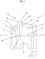
- a section of a cross-sectional view of an embodiment of the sash 1 according to the invention is shown using the example of a window sash with a plastic hollow profile frame formed sash frame 2, which is formed from mitred and welded sections of a window or door sash profile 3.
- the wing frame 2 of the wing 1 according to the invention is made of a thermoplastic polymer material, preferably polyvinyl chloride (PVC), in particular hard PVC (PVC-U) or glass fiber reinforced PVC, the additional additives such. B. stabilizers, plasticizers, pigments and the like are added. It is made up of a large number of hollow chambers, which are each surrounded by webs of the casement frame 2 .
- the profile of the casement 2 comprises a main hollow chamber 4, in which a non-illustrated reinforcement element, in particular a steel reinforcement, can be accommodated.
- the upper web 5 of the main hollow chamber 4 together with an external flap 6 forms a glazing rebate 7 with a rebate base 8.
- the profile 3 of the sash frame 2 has a glazing bead groove 9 in which a glazing bead 10 is anchored.
- a rebate space 11 that is at least partially open on one side is formed by the outer flap 6 , the rebate base 8 and the glazing bead 10 . Insulating glazing 12 is accommodated in the rebate space 11 on the face side.
- the insulating glazing 12 comprises two panes of glass 13, 13', in the space between which there is a negative pressure.
- the insulating glazing 12 is therefore a vacuum insulating glazing 12 .
- the vacuum insulating glazing 12 has a glass edge 14 directed towards the rebate base 8 .
- the glazing bead 10 comprises two glazing seals 15, 15', namely an upper glazing seal 15 that is further away from the rebate base 8 and a lower glazing seal 15' that is closer to the rebate base 8, with the two glass seals 15, 15' on the glazing bead 10 facing pane 13 'of the vacuum insulating glazing 12 abut.
- the two glass seals 15, 15' are extruded onto the glass bead 10 in the illustrated embodiment of the present invention.
- the glazing bead 10 is formed high in the illustrated embodiment.
- the main body of FIG. 10 and in particular that in FIG 1 illustrated installation position upper glass seal 15 'over the outer flap 6 of the wing profile 3 also.
- the glazing bead 10 even protrudes the rollover seal arranged on the outside rollover 6.
- the isotherms important for the formation of condensation water in a temperature range of +10° C. and +13° C. do not run on the room-side surface of the glass pane 13′ of the vacuum insulating glazing 12, but in the volume enclosed by the window sash 1 according to the invention. This significantly reduces the risk of condensation forming in this area.
- the glass inset of the vacuum insulating glazing 12 in the in 1 illustrated embodiment selected as large as possible.
- the glass edge 14 of the vacuum insulating glazing 12 is partially on the rebate base 8 .
- This also contributes to the course of the isotherms, which are important for the formation of condensation water, in a temperature range of +10° C. and +13° C. away from the room-side surface of the vacuum insulating glazing 12 through the vacuum insulating glazing 12 and the window sash profile 3 and through the window sash 1 according to the invention let the ingested volume run out. This also reduces the risk of condensation and thus mold growth.
- a section of a cross-sectional representation of a further embodiment of the window sash 1 according to the invention is shown, the sash frame 2 of which is in turn formed from cut and welded sections of a window sash profile 3 in the form of a plastic hollow chamber profile.
- the glazing bead 10 is compared to that in 1 embodiment shown is no longer so high.
- the upper glass seal 15' protrudes still the upper edge of the outer flap 6.
- the glass edge 14 of the vacuum insulating glazing 12 is partially on the rebate base 8 of the casement profile 3.
- a heat-conducting element 16 is arranged between the glazing bead 10 and the rebate base 8 .
- the heat-conducting element 16 comprises a metal sheet 17 made of a metal with a high thermal conductivity, in particular an aluminum sheet, and a support element 18, which in the embodiment shown is designed as a plastic profile made of polyvinyl chloride (PVC) and through which the heat-conducting element 16 rests on the fold base 8 stands.
- the aluminum sheet 17 rests on the room-side glass pane 13 ′ of the vacuum insulating glazing 12 .
- the aluminum sheet 17 extends approximately over the entire length between the glass pane 13' and the glazing bead 10.
- the aluminum sheet 17 is arranged in the rebate space 11 by the support element 18 in such a way that the distance between the aluminum sheet 17 and that in the installation situation according to 2 lower side of the glazing bead 10 is about 0.5 mm.
- the aluminum sheet 17 can also be in direct contact with the glazing bead 10 .
- Thermal energy from the interior of the room is transported directly to the surface of the glass pane 13 ′ of the vacuum insulating glazing 12 through the aluminum sheet 17 of the heat conducting element 16 , which also contributes to reduced condensation water formation on the surface of the vacuum insulating glazing 12 .
- window sash 1 is in 3 shown as a detail from a cross-sectional view.
- the sash frame 2 of the window sash according to the invention is also formed according to this embodiment from sections of a window sash profile 3 in the form of a plastic hollow chamber profile that are mitred and welded together.
- the installation situation according to FIG 3 upper glass seal 15', the upper edge of the outer flap 6 and the glass edge 14 of the vacuum insulating glazing 12 partially rests on the rebate base 8 of the casement profile 3, which in turn contributes to a less likely formation of condensation on the room-side surface of the glass pane 13' of the vacuum insulating glazing 12.
- the in 3 illustrated window sash 1 in turn comprises a heat-conducting element 16 as a further measure to reduce the risk of condensation.
- the heat-conducting element 16 is made entirely of a metal with high thermal conductivity, in particular aluminum.
- the heat-conducting element 16 comprises an aluminum sheet 17 folded over at one end, the aluminum sheet 17 resting with the folded-over end against the room-side glass pane 13 ′ of the vacuum insulating glazing 12 . From the room-side surface of the glass pane 13 ', the aluminum sheet 17 extends almost over the entire distance between the glass pane 13' and the groove-side profile wall of the glazing bead 10.
- Heat-conducting element 16 shown has two support elements 18, 18', with which the heat-conducting element 16 stands up on the fold base 8.
- the aluminum sheet 17 is arranged by the support elements 18, 18 'in the rebate 11 that the distance between the aluminum sheet 17 and in the installation situation according to 2 lower side of the glazing bead 10 is about 0.4 mm.
- thermal energy from the interior of the room reaches the surface of the room-side glass pane 13′ of the vacuum insulating glazing 12.
- the aforementioned measures largely reduce the likelihood of condensation forming on the surface of the glass pane 13′ and the associated mold growth.
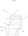
- the window 100 according to the invention comprises a window frame 19 which, in the illustrated embodiment, is formed from sections of a window frame profile 20 made of a plastic material, in particular PVC, which are mitred and welded together.
- the sash 1 according to the invention rests against the window frame 19 via a frame seal 21 and a stop seal 22 on the sash frame 3 when the window 100 according to the invention is closed.
- the sash 1 according to the invention is rotatably mounted on the window frame 19 via fittings (not shown).
Landscapes
- Engineering & Computer Science (AREA)
- Civil Engineering (AREA)
- Structural Engineering (AREA)
- Physics & Mathematics (AREA)
- Thermal Sciences (AREA)
- Securing Of Glass Panes Or The Like (AREA)
Applications Claiming Priority (1)
| Application Number | Priority Date | Filing Date | Title |
|---|---|---|---|
| DE102021134358.5A DE102021134358A1 (de) | 2021-12-22 | 2021-12-22 | Fenster- oder Türflügel sowie diesen umfassende(s) Fenster oder Tür |
Publications (3)
| Publication Number | Publication Date |
|---|---|
| EP4202169A1 true EP4202169A1 (fr) | 2023-06-28 |
| EP4202169B1 EP4202169B1 (fr) | 2025-10-01 |
| EP4202169C0 EP4202169C0 (fr) | 2025-10-01 |
Family
ID=84537892
Family Applications (1)
| Application Number | Title | Priority Date | Filing Date |
|---|---|---|---|
| EP22214471.9A Active EP4202169B1 (fr) | 2021-12-22 | 2022-12-19 | Battant de fenêtre ou de porte et fenêtre ou porte comprenant ledit battant |
Country Status (2)
| Country | Link |
|---|---|
| EP (1) | EP4202169B1 (fr) |
| DE (1) | DE102021134358A1 (fr) |
Citations (3)
| Publication number | Priority date | Publication date | Assignee | Title |
|---|---|---|---|---|
| WO2014008018A1 (fr) * | 2012-07-05 | 2014-01-09 | Guardian Industries Corp. | Procédé de pose de bloc fenêtre à vitrage isolant sous vide (vig) dans un vantail de fenêtre existant et procédé de remplacement de vitrage isolant sans vide par un vitrage isolant sous vide |
| DE102019107996A1 (de) * | 2018-09-25 | 2020-03-26 | SCHÜCO International KG | Rahmen für ein Fenster oder eine Tür |
| WO2020187977A1 (fr) | 2019-03-20 | 2020-09-24 | Harald Schulz | Structure formant cadre pour fenêtre, porte ou vitrage fixe |
Family Cites Families (1)
| Publication number | Priority date | Publication date | Assignee | Title |
|---|---|---|---|---|
| WO2020147908A1 (fr) | 2019-01-14 | 2020-07-23 | Vkr Holding A/S | Solution de cadre avec joint d'étanchéité venant en butée contre la surface d'une unité vig |
-
2021
- 2021-12-22 DE DE102021134358.5A patent/DE102021134358A1/de active Pending
-
2022
- 2022-12-19 EP EP22214471.9A patent/EP4202169B1/fr active Active
Patent Citations (3)
| Publication number | Priority date | Publication date | Assignee | Title |
|---|---|---|---|---|
| WO2014008018A1 (fr) * | 2012-07-05 | 2014-01-09 | Guardian Industries Corp. | Procédé de pose de bloc fenêtre à vitrage isolant sous vide (vig) dans un vantail de fenêtre existant et procédé de remplacement de vitrage isolant sans vide par un vitrage isolant sous vide |
| DE102019107996A1 (de) * | 2018-09-25 | 2020-03-26 | SCHÜCO International KG | Rahmen für ein Fenster oder eine Tür |
| WO2020187977A1 (fr) | 2019-03-20 | 2020-09-24 | Harald Schulz | Structure formant cadre pour fenêtre, porte ou vitrage fixe |
Also Published As
| Publication number | Publication date |
|---|---|
| EP4202169B1 (fr) | 2025-10-01 |
| EP4202169C0 (fr) | 2025-10-01 |
| DE102021134358A1 (de) | 2023-06-22 |
Similar Documents
| Publication | Publication Date | Title |
|---|---|---|
| EP2106491B1 (fr) | Profilé en matière plastique pour des éléments de fenêtre, de porte et de façade | |
| EP2240662A1 (fr) | Utilisation d'une matière plastique renforcée par fibres comme système de renforcement d'un profilé de cadre de fenêtre ou de porte | |
| DE202019107047U1 (de) | Fenster- oder Türflügel sowie diesen umfassendes Fenster oder diesen umfassende Tür | |
| EP2642060B1 (fr) | Battant de fenêtre ou de porte | |
| EP3660256B1 (fr) | Vantail de porte ou fenêtre, et porte ou fenêtre comprenant un tel vantail | |
| EP3825502B1 (fr) | Profilé de chambre creuse pour une fenêtre ou une porte ainsi que module de cadre comportant un tel profilé | |
| EP3922803A1 (fr) | Profilé d'extrusion, procédé de fabrication d'un profilé d'extrusion et système de porte et/ou de fenêtre | |
| EP4198244A1 (fr) | Battant de fenêtre ou de porte, dormant ainsi que fenêtre ou porte comprenant ceux-ci | |
| EP4202169B1 (fr) | Battant de fenêtre ou de porte et fenêtre ou porte comprenant ledit battant | |
| EP4202168B1 (fr) | Battant de fenêtre ou de porte et fenêtre ou porte comprenant ledit battant | |
| EP4575164A1 (fr) | Profilé creux de fenêtre ou de porte et joint d'angle le comprenant | |
| EP4198242A1 (fr) | Profilé creux pour une fenêtre ou une porte ainsi qu'ensemble cadre le comprenant | |
| DE202010003212U1 (de) | Rahmen eines Kunststofffensters oder einer Kunststofftür sowie Mitteldichtung hierfür | |
| WO2011047851A1 (fr) | Bâti de boîtier d'un dispositif de thermorégulation, et dispositif de thermorégulation comportant ce cadre | |
| WO2020187977A1 (fr) | Structure formant cadre pour fenêtre, porte ou vitrage fixe | |
| DE20315913U1 (de) | Rahmenprofil für ein Flächentragelement | |
| WO2019110472A1 (fr) | Profilé creux, en particuliers profilé de fenêtre ou de porte | |
| EP3828373A1 (fr) | Battant de fenêtre ou de porte ainsi que fenêtre ou porte comportant un tel battant | |
| EP3828372B1 (fr) | Battant de fenêtre ou de porte ainsi que fenêtre ou porte comportant un tel battant | |
| EP4015756B1 (fr) | Battant pour une fenêtre ou une porte, ainsi qu'élément de renfort pour un tel battant | |
| DE102024107624A1 (de) | Fenster- oder Türhohlkammerprofils sowie dieses umfassende Eck- verbindung | |
| EP4015746B1 (fr) | Liaison comprenant un battant pour une fenêtre ou une porte | |
| WO2019179912A1 (fr) | Profilé à chambres creuses pour une fenêtre ou une porte et ensemble d'encadrement le comportant | |
| EP4390038A1 (fr) | Battant pour une fenêtre ou une porte, fenêtre le comprenant et porte le comprenant | |
| EP3832063A1 (fr) | Support element for supporting a flat element in a leaf frame of a window or door leaf and this complete window or door leaf |
Legal Events
| Date | Code | Title | Description |
|---|---|---|---|
| PUAI | Public reference made under article 153(3) epc to a published international application that has entered the european phase |
Free format text: ORIGINAL CODE: 0009012 |
|
| STAA | Information on the status of an ep patent application or granted ep patent |
Free format text: STATUS: THE APPLICATION HAS BEEN PUBLISHED |
|
| AK | Designated contracting states |
Kind code of ref document: A1 Designated state(s): AL AT BE BG CH CY CZ DE DK EE ES FI FR GB GR HR HU IE IS IT LI LT LU LV MC ME MK MT NL NO PL PT RO RS SE SI SK SM TR |
|
| STAA | Information on the status of an ep patent application or granted ep patent |
Free format text: STATUS: REQUEST FOR EXAMINATION WAS MADE |
|
| STAA | Information on the status of an ep patent application or granted ep patent |
Free format text: STATUS: EXAMINATION IS IN PROGRESS |
|
| 17P | Request for examination filed |
Effective date: 20231221 |
|
| RBV | Designated contracting states (corrected) |
Designated state(s): AL AT BE BG CH CY CZ DE DK EE ES FI FR GB GR HR HU IE IS IT LI LT LU LV MC ME MK MT NL NO PL PT RO RS SE SI SK SM TR |
|
| 17Q | First examination report despatched |
Effective date: 20240125 |
|
| GRAP | Despatch of communication of intention to grant a patent |
Free format text: ORIGINAL CODE: EPIDOSNIGR1 |
|
| STAA | Information on the status of an ep patent application or granted ep patent |
Free format text: STATUS: GRANT OF PATENT IS INTENDED |
|
| INTG | Intention to grant announced |
Effective date: 20250423 |
|
| GRAS | Grant fee paid |
Free format text: ORIGINAL CODE: EPIDOSNIGR3 |
|
| GRAA | (expected) grant |
Free format text: ORIGINAL CODE: 0009210 |
|
| STAA | Information on the status of an ep patent application or granted ep patent |
Free format text: STATUS: THE PATENT HAS BEEN GRANTED |
|
| AK | Designated contracting states |
Kind code of ref document: B1 Designated state(s): AL AT BE BG CH CY CZ DE DK EE ES FI FR GB GR HR HU IE IS IT LI LT LU LV MC ME MK MT NL NO PL PT RO RS SE SI SK SM TR |
|
| REG | Reference to a national code |
Ref country code: GB Ref legal event code: FG4D Free format text: NOT ENGLISH Ref country code: CH Ref legal event code: F10 Free format text: ST27 STATUS EVENT CODE: U-0-0-F10-F00 (AS PROVIDED BY THE NATIONAL OFFICE) Effective date: 20251001 |
|
| REG | Reference to a national code |
Ref country code: DE Ref legal event code: R096 Ref document number: 502022005624 Country of ref document: DE |
|
| REG | Reference to a national code |
Ref country code: IE Ref legal event code: FG4D Free format text: LANGUAGE OF EP DOCUMENT: GERMAN |
|
| U01 | Request for unitary effect filed |
Effective date: 20251031 |
|
| PGFP | Annual fee paid to national office [announced via postgrant information from national office to epo] |
Ref country code: AT Payment date: 20260113 Year of fee payment: 4 |
|
| U07 | Unitary effect registered |
Designated state(s): AT BE BG DE DK EE FI FR IT LT LU LV MT NL PT RO SE SI Effective date: 20251210 |
|
| U20 | Renewal fee for the european patent with unitary effect paid |
Year of fee payment: 4 Effective date: 20251210 |
|
| PG25 | Lapsed in a contracting state [announced via postgrant information from national office to epo] |
Ref country code: ES Free format text: LAPSE BECAUSE OF FAILURE TO SUBMIT A TRANSLATION OF THE DESCRIPTION OR TO PAY THE FEE WITHIN THE PRESCRIBED TIME-LIMIT Effective date: 20251001 |
|
| PG25 | Lapsed in a contracting state [announced via postgrant information from national office to epo] |
Ref country code: NO Free format text: LAPSE BECAUSE OF FAILURE TO SUBMIT A TRANSLATION OF THE DESCRIPTION OR TO PAY THE FEE WITHIN THE PRESCRIBED TIME-LIMIT Effective date: 20260101 |
|
| PG25 | Lapsed in a contracting state [announced via postgrant information from national office to epo] |
Ref country code: HR Free format text: LAPSE BECAUSE OF FAILURE TO SUBMIT A TRANSLATION OF THE DESCRIPTION OR TO PAY THE FEE WITHIN THE PRESCRIBED TIME-LIMIT Effective date: 20251001 |
|
| PG25 | Lapsed in a contracting state [announced via postgrant information from national office to epo] |
Ref country code: RS Free format text: LAPSE BECAUSE OF FAILURE TO SUBMIT A TRANSLATION OF THE DESCRIPTION OR TO PAY THE FEE WITHIN THE PRESCRIBED TIME-LIMIT Effective date: 20260101 |
|
| PG25 | Lapsed in a contracting state [announced via postgrant information from national office to epo] |
Ref country code: IS Free format text: LAPSE BECAUSE OF FAILURE TO SUBMIT A TRANSLATION OF THE DESCRIPTION OR TO PAY THE FEE WITHIN THE PRESCRIBED TIME-LIMIT Effective date: 20260201 |
|
| PG25 | Lapsed in a contracting state [announced via postgrant information from national office to epo] |
Ref country code: CZ Free format text: LAPSE BECAUSE OF FAILURE TO SUBMIT A TRANSLATION OF THE DESCRIPTION OR TO PAY THE FEE WITHIN THE PRESCRIBED TIME-LIMIT Effective date: 20251001 |
|
| PG25 | Lapsed in a contracting state [announced via postgrant information from national office to epo] |
Ref country code: PL Free format text: LAPSE BECAUSE OF FAILURE TO SUBMIT A TRANSLATION OF THE DESCRIPTION OR TO PAY THE FEE WITHIN THE PRESCRIBED TIME-LIMIT Effective date: 20251001 |