EP4204273B1 - Protection prioritaire à consommation d'énergie réduite - Google Patents
Protection prioritaire à consommation d'énergie réduite Download PDFInfo
- Publication number
- EP4204273B1 EP4204273B1 EP20789021.1A EP20789021A EP4204273B1 EP 4204273 B1 EP4204273 B1 EP 4204273B1 EP 20789021 A EP20789021 A EP 20789021A EP 4204273 B1 EP4204273 B1 EP 4204273B1
- Authority
- EP
- European Patent Office
- Prior art keywords
- buffer
- anticlimber
- contact
- energy absorption
- energy
- Prior art date
- Legal status (The legal status is an assumption and is not a legal conclusion. Google has not performed a legal analysis and makes no representation as to the accuracy of the status listed.)
- Active
Links
Images





Classifications
-
- B—PERFORMING OPERATIONS; TRANSPORTING
- B61—RAILWAYS
- B61D—BODY DETAILS OR KINDS OF RAILWAY VEHICLES
- B61D15/00—Other railway vehicles, e.g. scaffold cars; Adaptations of vehicles for use on railways
- B61D15/06—Buffer cars; Arrangements or construction of railway vehicles for protecting them in case of collisions
-
- B—PERFORMING OPERATIONS; TRANSPORTING
- B61—RAILWAYS
- B61G—COUPLINGS; DRAUGHT AND BUFFING APPLIANCES
- B61G11/00—Buffers
- B61G11/16—Buffers absorbing shocks by permanent deformation of buffer element
-
- B—PERFORMING OPERATIONS; TRANSPORTING
- B61—RAILWAYS
- B61G—COUPLINGS; DRAUGHT AND BUFFING APPLIANCES
- B61G11/00—Buffers
- B61G11/18—Details
Definitions
- the invention relates to an energy absorption-reduced climbing protection device for rail vehicles according to claim 1 and a rail vehicle according to claim 10.
- the energy-absorbing buffers are used to convert the kinetic energy introduced during a collision into deformation energy when the impact energy that can be reversibly absorbed by the buffer is exceeded.
- the structures of rail vehicles are designed to absorb specific forces. If higher forces are expected in a collision than the characteristic curve of the energy-absorbing buffers and/or other energy-absorbing elements can cover, the structures must be designed accordingly stronger and therefore more expensive.
- the DE 10 2013 009 121 B3 an over-buffering protection for a crash buffer, arranged between the underframe for a railway wagon and the crash buffer, consisting of a base plate on the front side of the underframe of the railway wagon, wherein the base plate above the crash buffer has a folded area to which two different sides of the over-buffering protection are attached in the direction of travel, wherein one side of the over-buffering protection is fixed immovably and the other side of the over-buffering protection is movable in the direction of travel.
- the device is equipped with a base plate to which vertically aligned abutments in the form of plates are attached.
- Three pointed teeth are formed on the front face of each abutment, which in turn are mechanically connected to an adjacent abutment plate by horizontally running struts in the form of bars.
- the cutouts between the teeth are wider than the thickness of the connecting bars, so that in the event of a collision, the individual rows of teeth can penetrate into the recesses of the respective complementary anti-climbing device and interlock with it.
- the EP 2 033 868 A1 Describes an anti-climbing device for wagons in the form of bells or shoes, which are mounted on the front of a wagon frame together with a buffer. In the event of a collision, this anti-climbing device projects above and below the buffer in question. Rounded recesses are formed on the sides of the front side remote from the mounting, or a side wall is missing altogether.
- This design is intended to enable the upper and lower wall elements of the anti-climbing device to interlock, in order to form either a complementary anti-climbing device for the colliding wagon in the event of a collision or In the absence of such a buffer, the complementary buffer can be caught and thus prevent the colliding wagons from climbing up against each other.
- the EP 0 532 442 A1 discloses an anti-climbing device for wagons, but with two different designs, a female and a male, each in combination/interaction with an energy-absorbing buffer.
- the buffers are recessed into a recess in the front of the wagon frame so that, in the event of an overload, the excess energy is dissipated through permanent deformation of the energy-absorbing element of the buffer.
- the two anti-climbing devices move closer to each other in accordance with the axial displacement of the two buffer plates, so that they interlock and catch each other from the onset of permanent deformation of the buffer elements, preventing the wagons from climbing onto each other.
- the object of the present invention is to enable high operational reliability for rail vehicles while at the same time ensuring the most cost-effective construction of the rail vehicles.
- the invention relates to an energy absorption-reduced climbing protection for rail vehicles, for arrangement on a rail vehicle in the area of a buffer of the rail vehicle and for preventing the car body of the rail vehicle from being pushed over the car body of a colliding rail vehicle or vice versa, comprising a fastening section for fastening the anti-climbing device to the rail vehicle and/or to the buffer and a collision section for mechanical interaction with an anti-climbing device on the other colliding rail vehicle.
- the energy absorption-reduced climbing protection is characterized in that the collision section has a finger-like contact and guide section pointing in the direction of travel or opposite to the direction of travel, and a support section connecting the contact and guide section to the fastening section and oriented vertically to the direction of travel, wherein the contact and guide section and the support section together have at least two finger-like structures which radiate from a common center in their extension.
- the collision section facing in the direction of travel or opposite to the direction of travel with its finger-like contact and guidance section forms a comparatively small frontal area. This results in a high probability that, in the event of a collision, an anti-climbing device of the other colliding rail vehicle will pass this frontal area and subsequently hook into the collision section and/or the buffer, or conversely, that its own contact and guidance section will pass the collision section and/or the buffer of the other colliding rail vehicle without colliding with this frontal area.
- the support section which connects the contact and guide section with the fastening section and is aligned vertically to the direction of travel, absorbs the forces acting from the colliding rail vehicle in the event of a collision and transfers them into the car body of the own rail vehicle, either directly and/or via the fastening section and/or via the buffer.
- Reduced energy absorption means that if the front of the anti-climbing device collides with a collision object, e.g. the front of the anti-climbing device of another colliding rail vehicle, a certain impact energy is introduced into the anti-climbing device, but the anti-climbing device is designed to be so robust that no fundamental deformation of the anti-climbing device in the sense of an intended energy absorption can be caused.
- a collision object e.g. the front of the anti-climbing device of another colliding rail vehicle
- the rail vehicle's deformation system e.g., an energy-absorbing buffer
- the anti-climbing device does not generate any forces that would affect the energy absorption capacity of the rail vehicle's deformation system and thus its reproducibility.
- the rail vehicle can thus be manufactured with the minimum required structural stability, thus conserving resources and also cost-effectively.
- the at least two finger-like structures which radiate from a common center, widen the capture area of the anti-climbing device by spreading out in comparison to parallel aligned finger-like structures.
- the contact and guide section and the support section together with the finger-like structures, form the cross-sectional shape of a hand with fingers arranged one behind the other and angled at the base of the fingers to the back of the hand.
- This ensures excellent mutual interlocking of the anti-climbing device with a similarly designed anti-climbing device, the contact and guide section of which should enter the area between the contact and guide section and the buffer of the associated rail vehicle, or vice versa, for the contact and guide section of the anti-climbing device if it should enter the corresponding area of a colliding rail vehicle.
- the anti-climbing device can be directed towards the buffer and thus become further entangled if the energy resulting from the collision has not yet been completely dissipated and the anti-climbing device of the colliding rail vehicle is pushed further against its own anti-climbing device.
- the contact and guide section preferably comprises several, in particular three to five, fingers arranged next to one another. This can reinforce the anti-climbing protection with reduced energy absorption.
- the finger-like structures or fingers can be connected to each other by means of at least one stiffening element.
- the stiffening element Preferably in the area of the anti-climbing device facing the buffer, either between the fingers and/or on the side facing the buffer.
- stiffening element is connected to the fingers on the side of the fingers facing the buffer, e.g. in the form of a plate, this can form a sliding surface for another colliding anti-climbing device, on which the anti-climbing device is secured against climbing but is guided so as to be freely movable in the direction of the collision.
- At least one additional stiffening element is formed between at least two fingers, preferably in a vertical alignment with the first stiffening element. This can further increase the stiffening effect, in particular to prevent twisting of the fingers.
- the fingers can also have wedge-shaped tips at their ends, farther from the support section, when viewed from the side, preferably with a slope predominantly pointing away from the buffer. This allows them to form a so-called "sweep" in the transverse direction, essentially a narrow end face of a wedge resting flat on its underside.
- At least one further stiffening element can be formed between at least two fingers, preferably in vertical alignment with the first stiffening element.
- the finger-like contact and guide section viewed from the side, has a further bend, in the manner, compared to a hand and fingers arranged one behind the other and bent at an angle to the back of the hand in the finger root area, also in the first finger joint With angled fingers, this further improves the dissipation of the horizontal collision forces exerted by the other colliding anti-climbing device toward the associated buffer. Firstly, increasing the number of angles flattens the alignment of the adjacent areas relative to one another, and secondly, in the event of further collision, the trapped anti-climbing device repeatedly undergoes a forced change of direction toward the buffer.
- the fastening section is designed to be anodizable with respect to the buffer assigned to it on an energy absorption element and/or the buffer of the rail vehicle, so that the contact and guide section remains aligned in its orientation pointing in the direction of travel or against the direction of travel in the event of collision-related deformation of the buffer and/or the energy absorption element, without deformation of its structure in the sense of energy absorption to reduce the collision energy.
- Figure 1 A general representation of a possible arrangement of an energy-absorbing anti-climbing device 1 for a rail vehicle, for preventing the car body of the rail vehicle from sliding over the car body of a colliding rail vehicle, or vice versa.
- This anti-climbing device 1 is arranged on an energy-absorbing element and/or on a buffer 9 in a manner suitable for transmitting forces occurring in a collision between rail vehicles.
- the buffer 9 can also be designed in such a way that, in particular to reduce damage, In the event of a collision, energy is consumed, e.g., by deformation of material and/or destruction of correspondingly designed structures.
- the buffer 9 can be attached to the energy absorption element 10 and/or to the car body of the rail vehicle in a force-transmitting manner.
- the energy-absorbing anti-climbing device 1 for a rail vehicle comprises a fastening section 2, which, in the embodiment shown here, is attached to the energy-absorbing element 10 (see Fig. 1 , not shown here for reasons of clarity) and is attached to buffer 9.
- the energy-absorbing anti-climbing device 1 also includes a collision section 3 for mechanical interaction with an anti-climbing device on the other colliding rail vehicle.
- the collision section 3 has a contact and guide section 4, which is finger-like when viewed from the side, in the direction of travel or opposite to the direction of travel, and a support section 5, which connects the contact and guide section 4 to the fastening section 2 and is aligned vertically to the direction of travel.
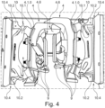
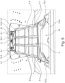
- the contact and guide section 4 can comprise several, in particular three to five, fingers 4.1 arranged next to one another; in the embodiments illustrated here as examples, four fingers 4.1. These fingers 4.1 are connected to one another by means of at least one stiffening element 4.2, preferably designed as a plate, in the area facing the buffer. This stiffening element 4.2 thus forms a sliding surface for a colliding anti-climbing device, along which it can slide in a trapped manner in the event of a sufficiently large anti-climbing force (cf. Figures 4 , 5 and 6 ).
- Further stiffening elements 4.3 are arranged vertically to the first stiffening element 4.2 between the fingers 4.1, in particular to stabilize them against tilting and/or to absorb or eliminate potentially occurring torques.
- the fingers 4.1 At their ends, remote from the support section 5, the fingers 4.1, viewed from the side, have wedge-shaped tips 4.4, with a slope predominantly pointing away from the buffer 9. In the event of a collision, this slope, on the one hand, lifts a locally higher, colliding anti-climbing device. On the other hand, in this case, it simultaneously pushes the anti-climbing device itself downward, causing it to be caught between the other colliding anti-climbing device and the buffer assigned to it, or, in the case of reversed local height positioning, with the opposite effect.
- the finger-like contact and guide section 4 has, viewed from the side, an angle 4.5, in the manner of a hand and one behind the other arranged and bent at an angle to the back of the hand in the finger root area, also fingers bent in the first finger joint (see Figure 3 ).
- the front end of the wedge-like tip 4.4 of the trapped, colliding anti-climbing device can be guided to hook against the buffer 9.
- the contact and guide section 4 is configured in relation to the buffer 9 assigned to it and can be arranged at a vertical distance therefrom such that a free space 4.6 is formed between the contact and guide section 4 and the buffer 9 to accommodate a similarly configured contact and guide section 4 of a collision-resistant, energy-absorbing anti-climbing device 1 for rail vehicles.
- the height of the free space 4.6 is approximately in the range of 1.3 times to, in particular, approximately 1.5 times the height.
- the length ratio of the side 4.1.1 of the contact and guide section 4 facing the buffer and the side 3.1.2 of the contact and guide section 4 facing away from the buffer are matched to one another in such a way that, in the event of a collision with another, similar anti-climbing device, the contact and guide section 4 of the colliding energy absorption-reduced anti-climbing device held in the free space 4.6 is trapped between the contact and guide section 4 and the buffer 9 of the energy absorption-reduced anti-climbing device in the vertical direction (cf. Figures 4 to 6 ).
- the contact and guide section 4 can thus be anodised in relation to the buffer 9 assigned to it on the rail vehicle (cf. Figures 1 , 2 , 7 and 8 ) that its tip is positioned in the longitudinal direction of the buffer 9 so far behind the buffer plate that the latter can develop its energy-absorbing effect unhindered by the energy-absorbing anti-climbing protection 1 (cf. Figures 4 to 6 ).
- Figure 3 also shows a further stabilization option, particularly against torques occurring during a collision, in that at least one finger 4.1 has a support element 4.1.0 at its end near the support section 5.
- a support element 4.1.0 at its end near the support section 5.
- the abutment is formed on an energy absorption element 10 (a so-called crash box).
- an energy absorption element 10 a so-called crash box.
- the support section 5 can be mechanically connected to the energy absorption element 10 (the crash box) in such a way that the energy acting in the event of a possible collision of the rail vehicle with another rail vehicle is introduced into the energy absorption element 10 (crash box) without deformation of the contact and guide section 4 or the support section 5.
- FIGS. 1 , 4 to 6 show, by way of example, several support elements 10.2 on the housing 10.3 of the energy absorption element 10, each designed in the form of an angle 10.2.
- the area surrounding the connection point of the support element 10.2 with the housing 10.3 can be Stabilized against the effects of torques occurring in a collision.
- These support elements 10.2 are preferably also attached to a mounting and/or end plate 10.4 and/or designed to be supported against a support structure formed on the car body of the rail vehicle in the event of a crash in order to further increase the stability effect.
- FIGS. 4 and 5 demonstrate the rotation-stabilizing effectiveness of these support elements 4.1.0 and 10.2, as well as their complementary elements, abutment 10.1 and mounting and/or end plate 10.4, after a crash. Both energy-absorbing anti-climbing devices remain essentially unchanged in their horizontal alignment after the crash. The energy dissipated during this crash was dissipated by the energy-absorbing element 10 and the buffer 9 through their intended deformation and machining.
Landscapes
- Engineering & Computer Science (AREA)
- Mechanical Engineering (AREA)
- Transportation (AREA)
- Vibration Dampers (AREA)
Claims (13)
- Dispositif antichevauchement (1) à absorption réduite d'énergie pour véhicules ferroviaires, destiné à être agencé sur un véhicule ferroviaire dans la zone d'un amortisseur (9) du véhicule ferroviaire et à empêcher le glissement les uns sur les autres du châssis de wagon du véhicule ferroviaire sur le châssis de wagon d'un véhicule ferroviaire entrant en collision ou inversement, comprenant une section de fixation (2) destinée à fixer le dispositif antichevauchement (1) sur le véhicule ferroviaire et/ou sur l'amortisseur (9) et une section de collision (3) destinée à interagir mécaniquement avec un dispositif antichevauchement sur un autre véhicule ferroviaire entrant en collision, la section de collision (3) présentant une zone de contact et de guidage (4) réalisée sous forme de doigts, orientée dans le sens de déplacement ou à l'opposé du sens de déplacement, et une section d'appui (5) reliant la section de contact et de guidage (4) à la section de fixation (2), orientée verticalement par rapport au sens de déplacement, caractérisé en ce que la section de contact et de guidage (4) et la section d'appui (5) présentent ensemble au moins deux structures de type doigt, qui partent radialement dans leur prolongement à partir d'un centre commun et qui élargissent, en divergeant, la zone de capture,
dans lequella section d'appui (5) est reliée à un élément d'absorption d'énergie (10) de manière à transmettre mécaniquement l'énergie de telle sorte que l'énergie agissant lors d'une collision éventuelle du véhicule ferroviaire avec un autre véhicule ferroviaire est introduite, sans déformation de la section de contact et de guidage (4) ou de la section d'appui (5), dans l'élément d'absorption d'énergie (10) eten ce qu'au moins un élément d'appui (10.2) sous forme d'une équerre (10.2) est agencé sur le boîtier (10.3) de l'élément d'absorption d'énergie (10), au moyen duquel élément la zone qui entoure le site de liaison de l'élément d'appui (10.2) au boîtier (10.3) est stabilisée par rapport à l'effet de couples de rotation survenant lors d'une collision, l'élément d'appui (10.2) étant de préférence également fixé à une plaque de montage et/ou de fermeture (10.4) et/ou réalisé de manière à pouvoir s'appuyer en cas de crash par rapport à une structure de butée réalisée sur le châssis de wagon du véhicule ferroviaire. - Dispositif antichevauchement à absorption réduite d'énergie selon la revendication 1, caractérisé en ce que la section de contact et de guidage (4) et la section d'appui (5) forment, conjointement avec les structures de type doigt, la forme transversale d'une main pourvue de doigts agencés les uns derrière les autres et pliés dans la zone de la base des doigts avec un angle par rapport au dos de la main.
- Dispositif antichevauchement à absorption réduite d'énergie selon l'une des revendications susmentionnées, caractérisé en ce que la section de contact et de guidage (4) comprend plusieurs, en particulier trois à cinq, doigts (4.1) agencés les uns à côté des autres.
- Dispositif antichevauchement à absorption réduite d'énergie selon la revendication 1 ou 2, caractérisé en ce que les doigts (4.1) sont reliés les uns aux autres au moyen d'au moins un élément raidisseur (4.2).
- Dispositif antichevauchement à absorption réduite d'énergie selon l'une des revendications précédentes, caractérisé en ce que l'élément raidisseur (4.2) est relié aux doigts sur le côté des doigts (4.1) orienté vers l'amortisseur.
- Dispositif antichevauchement à absorption réduite d'énergie selon l'une des revendications précédentes, caractérisé en ce qu'au moins un autre élément raidisseur (4.3) est réalisé entre au moins deux doigts (4.1), de préférence dans une orientation verticale par rapport au premier élément raidisseur (4.2).
- Dispositif antichevauchement à absorption réduite d'énergie selon l'une des revendications précédentes, caractérisé en ce que les doigts (4.1) présentent, au niveau de leurs extrémités éloignées de la section d'appui (5), vus latéralement, des pointes (4.4) en forme de coin, de préférence avec un biseau s'écartant principalement de l'amortisseur.
- Dispositif antichevauchement à absorption réduite d'énergie selon l'une des revendications précédentes, caractérisé en ce que la zone de contact et de guidage (4) réalisée sous forme de doigts, vue latéralement, présente un coude (4.5) de telle sorte que, par rapport à une main et des doigts agencés les uns derrière les autres et pliés dans la zone de la base des doigts avec un angle par rapport au dos de la main, les doigts sont également pliés au niveau de la première phalange.
- Dispositif antichevauchement à absorption réduite d'énergie selon l'une des revendications précédentes, caractérisé en ce qu'au moins un doigt (4.1) présente, au niveau de son extrémité proche de la section d'appui (5), un élément d'appui (4.1.0) sous la forme d'une structure, vue dans le prolongement de la direction des doigts, orientée vers l'arrière pour l'appui, en particulier pour l'appui des couples de rotation par rapport à une contrebutée (10.1), la contrebutée étant de préférence réalisée au niveau de l'élément d'absorption d'énergie (10), en particulier comme partie de sa paroi (10.3) de boîtier.
- Véhicule ferroviaire présentant au moins un amortisseur et un dispositif antichevauchement à absorption réduite d'énergie selon l'une des revendications précédentes, caractérisé en ce que la section de contact et de guidage (4) est agencée par rapport à l'amortisseur (9) qui y est associé et de manière écartée de celui-ci dans la direction verticale de telle sorte qu'un espace libre (4.6) est réalisé entre la section de contact et de guidage (4) et l'amortisseur (9), lequel espace est destiné à recevoir une section de contact et de guidage (4) réalisée de manière identique d'un dispositif antichevauchement (1) à absorption réduite d'énergie entrant en collision pour véhicules ferroviaires, la hauteur de l'espace libre (4.6) se situant environ dans la plage de 1,3 à, en particulier dans environ la plage de 1,5 fois la hauteur.
- Véhicule ferroviaire présentant au moins un amortisseur et un dispositif antichevauchement à absorption réduite d'énergie selon la revendication 10, caractérisé en ce que le rapport des longueurs du côté (4.1.1) de la section de contact et de guidage (4) orienté vers l'amortisseur et du côté (3.1.2) de la section de contact et de guidage (4) à l'opposé de l'amortisseur est adapté de telle sorte que lors d'une collision avec un autre dispositif antichevauchement du même type, la section de contact et de guidage (4) logée dans l'espace libre (4.6) du dispositif antichevauchement à absorption réduite d'énergie entrant en collision est capturée dans la direction verticale entre la section de contact et de guidage (4) et l'amortisseur (P) du dispositif antichevauchement à absorption réduite d'énergie.
- Véhicule ferroviaire présentant au moins un amortisseur et un dispositif antichevauchement à absorption réduite d'énergie selon l'une des revendications précédentes, caractérisé en ce que la section de contact et de guidage (4) est agencée sur le véhicule ferroviaire par rapport à l'amortisseur (9) qui lui est associé de manière telle que sa pointe est positionnée, dans la direction longitudinale de l'amortisseur (9), derrière l'assiette de l'amortisseur à une distance telle que celle-ci peut déployer sans encombre son effet d'absorption d'énergie du dispositif antichevauchement (1) à absorption réduite d'énergie.
- Véhicule ferroviaire présentant au moins un amortisseur et un dispositif antichevauchement à absorption réduite d'énergie selon l'une des revendications précédentes, caractérisé en ce que la section de fixation (2) est agencée, par rapport à l'amortisseur (9) qui lui est associé, sur un élément d'absorption d'énergie (10) et/ou l'amortisseur (9) du véhicule ferroviaire de manière telle que la section de contact et de guidage (4) reste orientée, lors d'une déformation provoquée par une collision de l'amortisseur (9) et/ou de l'élément d'absorption d'énergie (10), dans son orientation pointant dans le sens du déplacement ou, selon le cas, à l'opposé du sens du déplacement sans déformation de sa structure dans le sens d'une absorption d'énergie pour la réduction de l'énergie de collision.
Priority Applications (1)
| Application Number | Priority Date | Filing Date | Title |
|---|---|---|---|
| PL20789021.1T PL4204273T3 (pl) | 2020-10-01 | 2020-10-01 | Element przeciwnajazdowy o zmniejszonej zdolności pochłaniania energii |
Applications Claiming Priority (1)
| Application Number | Priority Date | Filing Date | Title |
|---|---|---|---|
| PCT/EP2020/077571 WO2022069052A1 (fr) | 2020-10-01 | 2020-10-01 | Protection prioritaire à consommation d'énergie réduite |
Publications (2)
| Publication Number | Publication Date |
|---|---|
| EP4204273A1 EP4204273A1 (fr) | 2023-07-05 |
| EP4204273B1 true EP4204273B1 (fr) | 2025-04-09 |
Family
ID=72811802
Family Applications (1)
| Application Number | Title | Priority Date | Filing Date |
|---|---|---|---|
| EP20789021.1A Active EP4204273B1 (fr) | 2020-10-01 | 2020-10-01 | Protection prioritaire à consommation d'énergie réduite |
Country Status (4)
| Country | Link |
|---|---|
| EP (1) | EP4204273B1 (fr) |
| ES (1) | ES3033549T3 (fr) |
| PL (1) | PL4204273T3 (fr) |
| WO (1) | WO2022069052A1 (fr) |
Family Cites Families (5)
| Publication number | Priority date | Publication date | Assignee | Title |
|---|---|---|---|---|
| FR2681300B1 (fr) * | 1991-09-12 | 1993-12-10 | Dietrich Cie Sa De | Dispositif d'antichevauchement et d'absorption d'energie pour vehicules ferroviaires. |
| ATE554984T1 (de) * | 2007-09-07 | 2012-05-15 | D Orval Atel | Überpufferungsschutzeinrichtung für eisenbahnwaggons, insbesondere tankwaggons |
| PL222364B1 (pl) * | 2012-11-06 | 2016-07-29 | Axtone Spółka Z Ograniczoną Odpowiedzialnością | Urządzenie zabezpieczające przed wspinaniem się wagonów kolejowych na siebie podczas zderzenia |
| DE102012221313B3 (de) * | 2012-11-22 | 2014-01-02 | Waggonbau Graaff Gmbh | Überpufferungsschutz für Schienenfahrzeuge |
| DE102013009121B3 (de) * | 2013-05-29 | 2014-07-31 | Waggonbau Graaff Gmbh | Überpufferungsschutz für Schienenfahrzeuge |
-
2020
- 2020-10-01 EP EP20789021.1A patent/EP4204273B1/fr active Active
- 2020-10-01 WO PCT/EP2020/077571 patent/WO2022069052A1/fr not_active Ceased
- 2020-10-01 ES ES20789021T patent/ES3033549T3/es active Active
- 2020-10-01 PL PL20789021.1T patent/PL4204273T3/pl unknown
Also Published As
| Publication number | Publication date |
|---|---|
| ES3033549T3 (en) | 2025-08-05 |
| WO2022069052A1 (fr) | 2022-04-07 |
| EP4204273A1 (fr) | 2023-07-05 |
| PL4204273T3 (pl) | 2025-08-04 |
Similar Documents
| Publication | Publication Date | Title |
|---|---|---|
| EP1990251B1 (fr) | Dispositif d'absorption d'énergie pour véhicules à éléments multiples | |
| DE102014223633B4 (de) | Stoßfängereinrichtung und Fahrzeug mit einer Stoßfängereinrichtung | |
| DE102016200983B4 (de) | Stoßfängeranordnung mit einem Stoßfängerquerträger für ein Kraftfahrzeug | |
| EP2455546A1 (fr) | Agencement de poteau pour une construction de glissière de sécurité et construction de glissière de sécurité pour sécuriser des bandes de roulement sur des chantiers | |
| EP3530544A1 (fr) | Dispositif de déformation pourvu de protection anti-chevauchement pour véhicules ferroviaires | |
| EP2920041B1 (fr) | Protection anti-montee | |
| EP4204273B1 (fr) | Protection prioritaire à consommation d'énergie réduite | |
| DE102006050028B4 (de) | Vorrichtung an der Fahrzeugfront von Schienenfahrzeugen | |
| EP1306281B1 (fr) | Dispositif d'anti-chevauchement pour véhicules ferroviaires avec tampons latéraux | |
| EP3924239B1 (fr) | Dispositif de protection anti-escalade | |
| DE202020005404U1 (de) | Stoßfängeranordnung für ein Kraftfahrzeug | |
| DE102012221313B3 (de) | Überpufferungsschutz für Schienenfahrzeuge | |
| EP2193970B1 (fr) | Tampon pour un véhicule ferroviaire | |
| EP1830003B1 (fr) | Amortisseur de choc avec segments de plaques | |
| EP2500228B1 (fr) | Véhicule ferroviaire doté d'un moyen de rappel pour la réduction du déplacement contre un partenaire de collision | |
| EP2904153B1 (fr) | Système de retenue et structure de transition entre deux systèmes de retenue de véhicules présentant des rigidités latérales différentes | |
| AT522658A1 (de) | Energieverzehreinrichtung | |
| DE102009052169A1 (de) | Überrollschutzvorrichtung | |
| EP3945161B1 (fr) | Absorbeur de choc pourvu de support d'extrémité | |
| WO2009019182A2 (fr) | Dispositif pour limiter le chevauchement d'un véhicule ferroviaire | |
| DE2707358A1 (de) | Zug- und stossvorrichtung fuer mittelpufferkupplungen von schienenfahrzeugen | |
| EP3631213B1 (fr) | Système de fixation | |
| EP3408119A1 (fr) | Véhicule automobile comportant une partie de véhicule déplaçable par rapport à la carrosserie du véhicule | |
| DE102022117602A1 (de) | Stoßfängeranordnung | |
| EP3608197A1 (fr) | Dispositif anti-chevauchement pourvu d'élément d'écran de protection |
Legal Events
| Date | Code | Title | Description |
|---|---|---|---|
| STAA | Information on the status of an ep patent application or granted ep patent |
Free format text: STATUS: UNKNOWN |
|
| STAA | Information on the status of an ep patent application or granted ep patent |
Free format text: STATUS: THE INTERNATIONAL PUBLICATION HAS BEEN MADE |
|
| PUAI | Public reference made under article 153(3) epc to a published international application that has entered the european phase |
Free format text: ORIGINAL CODE: 0009012 |
|
| STAA | Information on the status of an ep patent application or granted ep patent |
Free format text: STATUS: REQUEST FOR EXAMINATION WAS MADE |
|
| 17P | Request for examination filed |
Effective date: 20230320 |
|
| AK | Designated contracting states |
Kind code of ref document: A1 Designated state(s): AL AT BE BG CH CY CZ DE DK EE ES FI FR GB GR HR HU IE IS IT LI LT LU LV MC MK MT NL NO PL PT RO RS SE SI SK SM TR |
|
| DAV | Request for validation of the european patent (deleted) | ||
| DAX | Request for extension of the european patent (deleted) | ||
| GRAP | Despatch of communication of intention to grant a patent |
Free format text: ORIGINAL CODE: EPIDOSNIGR1 |
|
| STAA | Information on the status of an ep patent application or granted ep patent |
Free format text: STATUS: GRANT OF PATENT IS INTENDED |
|
| INTG | Intention to grant announced |
Effective date: 20241108 |
|
| GRAS | Grant fee paid |
Free format text: ORIGINAL CODE: EPIDOSNIGR3 |
|
| GRAA | (expected) grant |
Free format text: ORIGINAL CODE: 0009210 |
|
| STAA | Information on the status of an ep patent application or granted ep patent |
Free format text: STATUS: THE PATENT HAS BEEN GRANTED |
|
| AK | Designated contracting states |
Kind code of ref document: B1 Designated state(s): AL AT BE BG CH CY CZ DE DK EE ES FI FR GB GR HR HU IE IS IT LI LT LU LV MC MK MT NL NO PL PT RO RS SE SI SK SM TR |
|
| REG | Reference to a national code |
Ref country code: GB Ref legal event code: FG4D Free format text: NOT ENGLISH |
|
| REG | Reference to a national code |
Ref country code: CH Ref legal event code: EP |
|
| REG | Reference to a national code |
Ref country code: DE Ref legal event code: R096 Ref document number: 502020010802 Country of ref document: DE |
|
| REG | Reference to a national code |
Ref country code: IE Ref legal event code: FG4D Free format text: LANGUAGE OF EP DOCUMENT: GERMAN |
|
| REG | Reference to a national code |
Ref country code: ES Ref legal event code: FG2A Ref document number: 3033549 Country of ref document: ES Kind code of ref document: T3 Effective date: 20250805 |
|
| REG | Reference to a national code |
Ref country code: NL Ref legal event code: MP Effective date: 20250409 |
|
| PG25 | Lapsed in a contracting state [announced via postgrant information from national office to epo] |
Ref country code: NL Free format text: LAPSE BECAUSE OF FAILURE TO SUBMIT A TRANSLATION OF THE DESCRIPTION OR TO PAY THE FEE WITHIN THE PRESCRIBED TIME-LIMIT Effective date: 20250409 |
|
| PG25 | Lapsed in a contracting state [announced via postgrant information from national office to epo] |
Ref country code: PT Free format text: LAPSE BECAUSE OF FAILURE TO SUBMIT A TRANSLATION OF THE DESCRIPTION OR TO PAY THE FEE WITHIN THE PRESCRIBED TIME-LIMIT Effective date: 20250811 Ref country code: FI Free format text: LAPSE BECAUSE OF FAILURE TO SUBMIT A TRANSLATION OF THE DESCRIPTION OR TO PAY THE FEE WITHIN THE PRESCRIBED TIME-LIMIT Effective date: 20250409 |
|
| REG | Reference to a national code |
Ref country code: LT Ref legal event code: MG9D |
|
| PG25 | Lapsed in a contracting state [announced via postgrant information from national office to epo] |
Ref country code: NO Free format text: LAPSE BECAUSE OF FAILURE TO SUBMIT A TRANSLATION OF THE DESCRIPTION OR TO PAY THE FEE WITHIN THE PRESCRIBED TIME-LIMIT Effective date: 20250709 Ref country code: GR Free format text: LAPSE BECAUSE OF FAILURE TO SUBMIT A TRANSLATION OF THE DESCRIPTION OR TO PAY THE FEE WITHIN THE PRESCRIBED TIME-LIMIT Effective date: 20250710 |
|
| PGFP | Annual fee paid to national office [announced via postgrant information from national office to epo] |
Ref country code: TR Payment date: 20250924 Year of fee payment: 6 Ref country code: PL Payment date: 20250922 Year of fee payment: 6 |
|
| PG25 | Lapsed in a contracting state [announced via postgrant information from national office to epo] |
Ref country code: BG Free format text: LAPSE BECAUSE OF FAILURE TO SUBMIT A TRANSLATION OF THE DESCRIPTION OR TO PAY THE FEE WITHIN THE PRESCRIBED TIME-LIMIT Effective date: 20250409 |
|
| PG25 | Lapsed in a contracting state [announced via postgrant information from national office to epo] |
Ref country code: HR Free format text: LAPSE BECAUSE OF FAILURE TO SUBMIT A TRANSLATION OF THE DESCRIPTION OR TO PAY THE FEE WITHIN THE PRESCRIBED TIME-LIMIT Effective date: 20250409 |
|
| PG25 | Lapsed in a contracting state [announced via postgrant information from national office to epo] |
Ref country code: RS Free format text: LAPSE BECAUSE OF FAILURE TO SUBMIT A TRANSLATION OF THE DESCRIPTION OR TO PAY THE FEE WITHIN THE PRESCRIBED TIME-LIMIT Effective date: 20250709 |
|
| PGFP | Annual fee paid to national office [announced via postgrant information from national office to epo] |
Ref country code: CZ Payment date: 20250918 Year of fee payment: 6 |
|
| PGFP | Annual fee paid to national office [announced via postgrant information from national office to epo] |
Ref country code: RO Payment date: 20250930 Year of fee payment: 6 |
|
| PG25 | Lapsed in a contracting state [announced via postgrant information from national office to epo] |
Ref country code: IS Free format text: LAPSE BECAUSE OF FAILURE TO SUBMIT A TRANSLATION OF THE DESCRIPTION OR TO PAY THE FEE WITHIN THE PRESCRIBED TIME-LIMIT Effective date: 20250809 |
|
| PG25 | Lapsed in a contracting state [announced via postgrant information from national office to epo] |
Ref country code: LV Free format text: LAPSE BECAUSE OF FAILURE TO SUBMIT A TRANSLATION OF THE DESCRIPTION OR TO PAY THE FEE WITHIN THE PRESCRIBED TIME-LIMIT Effective date: 20250409 |
|
| PGFP | Annual fee paid to national office [announced via postgrant information from national office to epo] |
Ref country code: DE Payment date: 20251020 Year of fee payment: 6 |
|
| REG | Reference to a national code |
Ref country code: DE Ref legal event code: R097 Ref document number: 502020010802 Country of ref document: DE |
|
| PG25 | Lapsed in a contracting state [announced via postgrant information from national office to epo] |
Ref country code: SM Free format text: LAPSE BECAUSE OF FAILURE TO SUBMIT A TRANSLATION OF THE DESCRIPTION OR TO PAY THE FEE WITHIN THE PRESCRIBED TIME-LIMIT Effective date: 20250409 Ref country code: DK Free format text: LAPSE BECAUSE OF FAILURE TO SUBMIT A TRANSLATION OF THE DESCRIPTION OR TO PAY THE FEE WITHIN THE PRESCRIBED TIME-LIMIT Effective date: 20250409 |
|
| PGFP | Annual fee paid to national office [announced via postgrant information from national office to epo] |
Ref country code: FR Payment date: 20251024 Year of fee payment: 6 |
|
| PG25 | Lapsed in a contracting state [announced via postgrant information from national office to epo] |
Ref country code: EE Free format text: LAPSE BECAUSE OF FAILURE TO SUBMIT A TRANSLATION OF THE DESCRIPTION OR TO PAY THE FEE WITHIN THE PRESCRIBED TIME-LIMIT Effective date: 20250409 |
|
| PG25 | Lapsed in a contracting state [announced via postgrant information from national office to epo] |
Ref country code: SK Free format text: LAPSE BECAUSE OF FAILURE TO SUBMIT A TRANSLATION OF THE DESCRIPTION OR TO PAY THE FEE WITHIN THE PRESCRIBED TIME-LIMIT Effective date: 20250409 |
|
| PG25 | Lapsed in a contracting state [announced via postgrant information from national office to epo] |
Ref country code: IT Free format text: LAPSE BECAUSE OF FAILURE TO SUBMIT A TRANSLATION OF THE DESCRIPTION OR TO PAY THE FEE WITHIN THE PRESCRIBED TIME-LIMIT Effective date: 20250409 |
|
| PGFP | Annual fee paid to national office [announced via postgrant information from national office to epo] |
Ref country code: ES Payment date: 20251114 Year of fee payment: 6 |
|
| PLBE | No opposition filed within time limit |
Free format text: ORIGINAL CODE: 0009261 |
|
| STAA | Information on the status of an ep patent application or granted ep patent |
Free format text: STATUS: NO OPPOSITION FILED WITHIN TIME LIMIT |
|
| REG | Reference to a national code |
Ref country code: CH Ref legal event code: L10 Free format text: ST27 STATUS EVENT CODE: U-0-0-L10-L00 (AS PROVIDED BY THE NATIONAL OFFICE) Effective date: 20260218 |
|
| 26N | No opposition filed |
Effective date: 20260112 |