EP4214689B1 - Procédé de détection d'une manipulation ou d'une contrefaçon d'un objet et système correspondant - Google Patents
Procédé de détection d'une manipulation ou d'une contrefaçon d'un objet et système correspondant Download PDFInfo
- Publication number
- EP4214689B1 EP4214689B1 EP21777990.9A EP21777990A EP4214689B1 EP 4214689 B1 EP4214689 B1 EP 4214689B1 EP 21777990 A EP21777990 A EP 21777990A EP 4214689 B1 EP4214689 B1 EP 4214689B1
- Authority
- EP
- European Patent Office
- Prior art keywords
- information
- graphic representation
- recording
- identifier
- data structure
- Prior art date
- Legal status (The legal status is an assumption and is not a legal conclusion. Google has not performed a legal analysis and makes no representation as to the accuracy of the status listed.)
- Active
Links
Images

Classifications
-
- G—PHYSICS
- G06—COMPUTING OR CALCULATING; COUNTING
- G06V—IMAGE OR VIDEO RECOGNITION OR UNDERSTANDING
- G06V20/00—Scenes; Scene-specific elements
- G06V20/95—Pattern authentication; Markers therefor; Forgery detection
-
- G—PHYSICS
- G06—COMPUTING OR CALCULATING; COUNTING
- G06V—IMAGE OR VIDEO RECOGNITION OR UNDERSTANDING
- G06V10/00—Arrangements for image or video recognition or understanding
- G06V10/20—Image preprocessing
- G06V10/24—Aligning, centring, orientation detection or correction of the image
-
- G—PHYSICS
- G06—COMPUTING OR CALCULATING; COUNTING
- G06V—IMAGE OR VIDEO RECOGNITION OR UNDERSTANDING
- G06V10/00—Arrangements for image or video recognition or understanding
- G06V10/70—Arrangements for image or video recognition or understanding using pattern recognition or machine learning
- G06V10/74—Image or video pattern matching; Proximity measures in feature spaces
- G06V10/75—Organisation of the matching processes, e.g. simultaneous or sequential comparisons of image or video features; Coarse-fine approaches, e.g. multi-scale approaches; using context analysis; Selection of dictionaries
- G06V10/751—Comparing pixel values or logical combinations thereof, or feature values having positional relevance, e.g. template matching
-
- G—PHYSICS
- G07—CHECKING-DEVICES
- G07D—HANDLING OF COINS OR VALUABLE PAPERS, e.g. TESTING, SORTING BY DENOMINATIONS, COUNTING, DISPENSING, CHANGING OR DEPOSITING
- G07D7/00—Testing specially adapted to determine the identity or genuineness of valuable papers or for segregating those which are unacceptable, e.g. banknotes that are alien to a currency
- G07D7/004—Testing specially adapted to determine the identity or genuineness of valuable papers or for segregating those which are unacceptable, e.g. banknotes that are alien to a currency using digital security elements, e.g. information coded on a magnetic thread or strip
- G07D7/0043—Testing specially adapted to determine the identity or genuineness of valuable papers or for segregating those which are unacceptable, e.g. banknotes that are alien to a currency using digital security elements, e.g. information coded on a magnetic thread or strip using barcodes
-
- G—PHYSICS
- G07—CHECKING-DEVICES
- G07D—HANDLING OF COINS OR VALUABLE PAPERS, e.g. TESTING, SORTING BY DENOMINATIONS, COUNTING, DISPENSING, CHANGING OR DEPOSITING
- G07D7/00—Testing specially adapted to determine the identity or genuineness of valuable papers or for segregating those which are unacceptable, e.g. banknotes that are alien to a currency
- G07D7/004—Testing specially adapted to determine the identity or genuineness of valuable papers or for segregating those which are unacceptable, e.g. banknotes that are alien to a currency using digital security elements, e.g. information coded on a magnetic thread or strip
- G07D7/0047—Testing specially adapted to determine the identity or genuineness of valuable papers or for segregating those which are unacceptable, e.g. banknotes that are alien to a currency using digital security elements, e.g. information coded on a magnetic thread or strip using checkcodes, e.g. coded numbers derived from serial number and denomination
-
- G—PHYSICS
- G07—CHECKING-DEVICES
- G07D—HANDLING OF COINS OR VALUABLE PAPERS, e.g. TESTING, SORTING BY DENOMINATIONS, COUNTING, DISPENSING, CHANGING OR DEPOSITING
- G07D7/00—Testing specially adapted to determine the identity or genuineness of valuable papers or for segregating those which are unacceptable, e.g. banknotes that are alien to a currency
- G07D7/06—Testing specially adapted to determine the identity or genuineness of valuable papers or for segregating those which are unacceptable, e.g. banknotes that are alien to a currency using wave or particle radiation
- G07D7/12—Visible light, infrared or ultraviolet radiation
-
- G—PHYSICS
- G07—CHECKING-DEVICES
- G07D—HANDLING OF COINS OR VALUABLE PAPERS, e.g. TESTING, SORTING BY DENOMINATIONS, COUNTING, DISPENSING, CHANGING OR DEPOSITING
- G07D7/00—Testing specially adapted to determine the identity or genuineness of valuable papers or for segregating those which are unacceptable, e.g. banknotes that are alien to a currency
- G07D7/20—Testing patterns thereon
- G07D7/202—Testing patterns thereon using pattern matching
- G07D7/2033—Matching unique patterns, i.e. patterns that are unique to each individual paper
-
- G—PHYSICS
- G06—COMPUTING OR CALCULATING; COUNTING
- G06V—IMAGE OR VIDEO RECOGNITION OR UNDERSTANDING
- G06V20/00—Scenes; Scene-specific elements
- G06V20/60—Type of objects
- G06V20/62—Text, e.g. of license plates, overlay texts or captions on TV images
- G06V20/625—License plates
-
- G—PHYSICS
- G06—COMPUTING OR CALCULATING; COUNTING
- G06V—IMAGE OR VIDEO RECOGNITION OR UNDERSTANDING
- G06V30/00—Character recognition; Recognising digital ink; Document-oriented image-based pattern recognition
- G06V30/40—Document-oriented image-based pattern recognition
- G06V30/42—Document-oriented image-based pattern recognition based on the type of document
-
- G—PHYSICS
- G07—CHECKING-DEVICES
- G07D—HANDLING OF COINS OR VALUABLE PAPERS, e.g. TESTING, SORTING BY DENOMINATIONS, COUNTING, DISPENSING, CHANGING OR DEPOSITING
- G07D2207/00—Paper-money testing devices
Definitions
- the subject of the present invention is a method for detecting manipulation or forgery of an object that is marked with a graphic representation of information.
- the subject of the present invention is also a system for detecting manipulation of an object that is marked with a graphic representation of information.
- the graphic representation of the information can in particular be in the form of a 1D code such as a barcode or a 2D code such as a QR code or a data matrix code.
- the information can also be in plain text.
- a method for detecting an unauthorized copy of such an object is also disclosed.
- a wide variety of methods are known from the state of the art for verifying the authenticity of a document that is provided with a graphic representation of information. Newer methods make particular use of the fact that the surface of such a document in a test area already has irregular structures, for example during production, which are characteristic of the specific document and cannot be replicated on another document or can only be replicated with very high technical effort.
- the surface is provided with an artificial irregular structure in a test area as part of a generic method, e.g. by providing the surface in the test area with a random pattern of paint splashes.
- an unprocessed or processed reference image of the test area of the document is stored in a database in a registration step.
- another image of the test area of the document is created and compared with the reference image stored in the database. This technique is also known under the keyword "physical unclonable function" (PUF for short).
- a method for producing security markings whereby these security markings have a Random patterns can be included. This random pattern can be read in and a corresponding "fingerprint" created, which is then compared with the recorded pattern during authentication.
- a unique identification number can be used together with the "fingerprint”.
- the extracted fingerprint can also be saved in a suitable graphic representation on the object to be marked.
- WO 2019/197628 A1 This generally describes a method for optical product authentication.
- the product can be coated with a film that contains randomly distributed, reflective and/or luminescent particles. This particle distribution is recorded and saved as a reference image. A recognition image can then be compared with the previously saved reference image.
- an overlay of the particles with a QR code is disclosed, whereby the QR code is intended to enable digital image registration between the recognition image and the reference image.
- the US 2014/0168690 A1 and the EP 2 724 332 B1 Method for checking documents whereby the surface quality (microstructure) of the object in the area of, for example, printed information (e.g. a serial number) is analyzed and used to generate a reference identifier. This is then stored together with the information and used for checking at a later time.
- printed information e.g. a serial number
- a disadvantage of the methods known from the prior art is that they allow verification of the authenticity of the object carrying the information, but not verification of the authenticity of the information itself.
- Its task is to provide a method for detecting manipulation of an object that is marked with a graphic representation of information.
- the task of the present invention is to provide a system for detecting manipulation of an object that is marked with a graphic representation of information. In both cases, the manipulation can affect both the object itself and the graphic representation. concerning the information.
- the term “approximately” used in the present application indicates a tolerance range that the person skilled in the art in the field in question considers to be usual.
- the term “approximately” is to be understood as a tolerance range of the reference size of up to a maximum of +/-20%, preferably up to a maximum of +/-10%.
- the method according to the invention is intended for the forgery-proof marking of an object with a graphic representation of information, whereby the information can be, for example, a serial number of the object marked with the information.
- a serial number is to be understood as any identifier that uniquely identifies the marked object.
- the information can also relate to the identity of the manufacturer or distributor of the object or the owner or possessor of the object. In principle, the subject of the information is not limited within the context of the present invention.
- the object provided with a forgery-proof marking is particularly preferably an official document, e.g. a driver's license, an official certificate or an identification document such as an identity card or a passport, a means of payment such as a banknote, a credit card or a cheque, a security, an official registration document such as a vehicle registration document or an official proof of validity such as registration papers or a vignette for road use, or a vehicle license plate.
- a vehicle license plate can also be a so-called 3rd license plate, which is intended to be arranged in the interior of a motor vehicle.
- a contrast-providing microstructure is understood to be a structure that can be detected by optical means.
- such a microstructure should be recognizable by means of an optical image of the relevant surface area, e.g. by means of a photograph.
- the structure size of such a microstructure should preferably be smaller than the characteristic dimensions of the graphic representation of the information.
- the contrast-generating microstructure may already have been created during the manufacture of the object; in particular, it may be an inherent product feature of the object.
- the characteristic dimensions of the graphical representation of the information are advantageously chosen to be adapted to the structure size of the microstructure.
- the article is a retroreflective film based on spherical transparent beads embedded in a transparent matrix.
- such an article can be a retroreflective vehicle license plate, which can in particular be provided with an individual legend.
- the microstructure may also have been produced in upstream process steps on or in the article, e.g. by means of a suitable printing process, e.g. by means of the DE 103 04 805 A1 known printing process.
- the structure size of the generated microstructure is advantageously selected to match the desired characteristic dimensions of the graphic representation of the information.
- the invention is based on the fact that a graphic representation of the information is present, in particular in plain text or in the form of a 1D code such as a barcode or a 2D code such as a QR code or a data matrix code.
- An advantageous development of the method according to the invention further comprises the method step of generating a graphic representation of the information.
- the invention assumes that the object is marked with the graphic representation of the information, whereby regions are formed which have a machine-detectable contrast to the surrounding surface regions of the object.
- the aforementioned contrast-generating microstructure of the surface of the object can also be produced by the object having a microstructure in its interior which, when the graphic representation of the information is applied to the object, serves to form a contrast-generating microstructure on the surface of the object, which then becomes visible, ie detectable by means of image processing.
- the graphic representation of the information is generated by means of laser marking of the object.
- a further advantageous development of the method according to the invention therefore further comprises the method step of marking the object with the graphic representation of the information.
- areas are formed on the object by suitable treatment such as laser irradiation or printing, which are optically detectable on the surface of the object against the background of the untreated surface of the object. These areas have a machine-detectable contrast to the surrounding surface areas of the object.
- an area that has a machine-detectable contrast to the surrounding surface areas of the object can be a surface area whose brightness value or color value is measurably different from that of the surrounding surface areas of the object.
- this is referred to as the formation of light and dark areas, since at least the brightness values or the color values of these areas differ measurably from one another.
- the bright areas can be formed from the untreated background of the area of the object provided with the graphic representation of the information.
- the dark areas can be formed by the treated surface areas. In particular, they can appear black.
- both the light and the dark areas of the respective code usually encode the information contained therein.
- the subsequent process steps which serve the purpose of product validation, are carried out at a later date in order to check an object that is at least at first glance identical to the object marked with the graphic representation of the information in the first steps to see whether it is actually the object marked during product registration or whether the object is marked with the information that was applied to the registered object during product registration.
- the process only produces a positive test result if the validated object is actually the registered object and if the product validation shows that the information with which the validated object is marked is identical to the information arranged on the registered object in the registration step.
- the method according to the invention does not necessarily require the information to be extracted from the test recording. Nevertheless, the method allows the information attached to the object to be categorized as manipulated/not manipulated.
- the reference identifier is stored together with the information in the data structure during product registration.
- the reference identifier on which the validation is based is retrieved from the data structure using the information.
- This procedure allows an identifier stored in the data structure that is assigned to the object to be validated to be retrieved in a resource-saving manner.
- the procedure for determining the degree of agreement between the test identifier and the reference identifier retrieved from the data structure only needs to be carried out once.
- the information is not stored together with the reference identifier in the data structure during product registration. Without further measures, there is therefore no possibility of specifically retrieving a reference identifier from the database that is to be used for validation.
- the method for determining the degree of agreement between the check identifier and the reference identifier retrieved from the data structure is therefore usually carried out repeatedly, until either in method step h. an extracted piece of information provides the result "not manipulated” or until all reference identifiers stored in the data structure have been categorized as "manipulated".
- the item checked is the item registered during product registration and the information extracted is the information that was placed on the registered item during product registration. Therefore, there is no tampering or forgery.
- the item being checked is either not the item registered during product registration or/and the information extracted is not the information that was placed on the registered item during product registration. This therefore constitutes manipulation or falsification.
- the data structure is located on the object itself.
- the data structure is designed directly as a graphic coding of the reference identifier, which is arranged in a suitable manner on the object.
- 1D codes such as barcodes
- 2D codes such as QR codes or data matrix codes have proven to be suitable graphic codings.
- plain text is used as graphic coding of the reference identifier.
- the graphic coding is arranged on the object in such a way that manipulation of the graphic coding is made difficult.
- This can be achieved by applying the marking to the object by means of a local, irreversible change to the material of the object, e.g. by means of laser marking.
- laser marking can in particular also be incorporated into the material of the object and is not limited to a purely superficial change to the material of the object.
- the object is at least partially transparent, e.g. by having a transparent layer on the surface, which can be designed as a (partially) transparent film, for example.
- the data structure is designed as a memory chip that is firmly connected to the object.
- this can be a memory chip whose memory content can be read out using wireless communication, for example an RFID chip or an NFC chip.
- the reference identifier is stored in digital form in the memory chip and can be retrieved from it using suitable reading devices.
- the reference identifier is stored in encrypted form in the memory chip
- the memory chip is configured for encrypted wireless communication with a suitable reader.
- the data structure is formed separately from the object.
- the data structure is designed analogously to the above embodiment, ie as a graphic coding or as a reference identifier stored in digital form in a suitable storage medium.
- the data structure is not designed on the object itself, but on a separately designed object.
- the object and the further, separately designed object are arranged separately from one another during normal use.
- a vehicle license plate with a license plate legend that is used worldwide for attachment to the exterior of a motor vehicle can be mentioned as an object and as a further, separately designed object a
- a third license plate which is typically located in the interior of a motor vehicle, e.g. on the windshield or a side window of the vehicle.
- the data structure is designed as a database that can be accessed by a suitably designed reading device via a network in order to at least read data stored in the database, in particular reference identifiers.
- the database may be stored on a medium connected to the Internet or another digital communications network, for example a server or a network storage medium, both of which may advantageously be cloud-based.
- the method according to the invention offers a very high degree of security against forgery by interweaving coded information with the irregular microstructure of the object. This means that the authenticity of the validated object and the coded information arranged therein can be assumed with very good certainty if the extracted information is categorized as "not manipulated" using the method according to the invention.
- the reference identifier was linked to the information when it was stored in the data structure in such a way that the linked reference identifier can be retrieved from the data structure by specifying the information.
- the one reference identifier that is linked to the object to be checked can be retrieved from the data structure by specifying the information decoded from the graphic marking.
- This is particularly advantageous if not just a single reference identifier is stored in the data structure, but a large number of reference identifiers that would otherwise have to be checked for agreement with the test identifier as part of the method according to the invention until either a positive test result is available, i.e. at least a preset minimum degree of agreement is reached, or until the comparison of the test identifier with all reference identifiers stored in the data structure has produced a negative test result.
- This further development of the method according to the invention therefore allows a particularly resource-saving process.
- a position correction of the image to be analyzed is carried out in the bright and/or dark areas during the spatially resolved analysis of the reference image and/or the test image. This can serve in particular to ensure a consistent orientation of the graphic representation of the information present in both the reference image and the test image. This facilitates the implementation of the method to be carried out according to the invention for determining the degree of agreement between reference recording and image recording is made much easier. In addition, the method can produce more reliable results.
- a size correction of the image to be analyzed is carried out in the bright and/or dark areas during the spatially resolved analysis of the reference image and/or the test image. This can be used in particular to ensure that the graphic representation of the information present in both the reference image and the test image is the same size. This also significantly simplifies the implementation of the method to be carried out according to the invention for determining the degree of agreement between the reference image and the test image. In addition, the method can achieve even more reliable results.
- both the aforementioned position correction and the aforementioned size correction are carried out using at least a subset of the light and/or dark areas.
- all light and/or dark areas that make up the graphic representation of the information can also be used for the aforementioned correction steps.
- the above-mentioned correction steps are particularly easy to carry out if the graphic representation of the information is in the form of a standardized machine-readable font, in particular in the form of a 1D code such as a barcode, or a 2D code such as a QR code or a data matrix code.
- the analyzed bright and/or dark areas are broken down into a predetermined number of subsections, wherein these subsections particularly preferably have the same size.
- the characteristic dimensions of the subsections are selected such that they are larger than the structural size of the microstructure on the object, which is used in the process according to the invention.
- the characteristic dimensions of the subsections are at least twice as large as the structural size of the microstructure, particularly preferably at least five times as large and especially preferably at least ten times as large.
- a brightness or color value is assigned to the analyzed image sections during the spatially resolved analysis of the reference and/or test image.
- the identifier generated in each case is based at least on the assigned brightness or color values of the analyzed image sections.
- the identifier generated in each case is at least based on labels that identify the analyzed image sections.
- these labels can number the image sections or indicate the position of the individual image sections in a reference coordinate system.
- a system according to the invention for detecting manipulation of an object that is marked with a graphic representation of information, wherein the object is marked with a graphic representation of the information, in particular in plain text or in the form of a 1D code such as a barcode or a 2D code such as a QR code or a data matrix code, with the formation of light and dark areas. Furthermore, the functioning of the system according to the invention is based on the object having a surface with a contrasting, irregular microstructure.
- the analysis unit, the decoding unit, the comparison unit and/or the categorization unit are implemented in software.
- At least two functional units of the group consisting of analysis unit, decoding unit, comparison unit and categorization unit are formed in a common device, preferably at least three functional units and particularly preferably all four functional units.
- the aforementioned device is designed to be portable, in particular as a notebook, as a tablet computer, as a mobile digital device or as a smartphone.
- the aforementioned device is integrated into a machine for mechanically treating the object.
- Mechanical treatment is understood to mean, for example, printing, laminating, engraving or mechanical forming.
- the aforementioned device can be integrated into a license plate press which is designed to provide a vehicle license plate with a printed or preferably embossed license plate legend.
- the camera of the system according to the invention is integrated into the aforementioned device.
- the camera can also be designed separately from the aforementioned device.
- the camera is preferably arranged in a portable device in the form of a handheld device, which is suitable for being carried around at all times by a person entrusted with the inspection task, in particular in a mobile phone or a tablet computer.
- the camera which is designed separately from the aforementioned device, is configured for wireless or wired communication with the aforementioned device, in particular via a wired or wireless IP-based communication network such as a cellular network or via a short-range wireless communication network such as WiFi or Bluetooth ® .
- a wired or wireless IP-based communication network such as a cellular network or via a short-range wireless communication network such as WiFi or Bluetooth ® .
- the camera may be suitable or even optimized for use in the visible spectral range.
- the camera can be set up to work outside the visible spectral range, in particular in the IR or UV range. This is particularly advantageous if the graphic representation of the information is arranged on the object in such a way that a contrast sufficient to carry out the method according to the invention is only or in particular in at least one of the spectral ranges mentioned.
- a recording of the graphic representation of the information is generated in the visible spectral range.
- a recording of the graphic representation of the information is generated outside the visible spectral range, in particular in the IR or UV range.
- the camera has a control unit which is designed to trigger the recording of an image with the camera only when sufficient lighting conditions are present.
- sufficient lighting conditions are to be understood as meaning that to reliably analyze the image of the surface area of the object in which the graphic representation of the information is arranged, created under such exposure conditions, by the analysis unit.
- the system according to the invention further comprises a decoding unit which is designed to extract the information encoded therein from a recording made by the camera of the surface area of the object in which the graphic representation of the information is arranged.
- the system according to the invention is designed to make the information extracted by the decoding unit available for further processing.
- the decoding unit can be designed to be suitable for this purpose.
- the system according to the invention can form an interface suitable for this purpose.
- the system further comprises a non-volatile memory unit for storing the data structure.
- the non-volatile memory unit is arranged on the object itself.
- the non-volatile data structure is formed separately from the object.
- the data structure is designed so that an identifier can be stored together with the information in the data structure.
- the data structure is designed such that an identifier stored in the data structure can be retrieved using the information from the data structure.
- An example here is the serial number of a vehicle license plate and, as an object correlated with the vehicle license plate, a vehicle which is clearly identified by a serial number in the form of a chassis number.
- the surface of the object is covered with a glass bead-based retroreflective film, such as that offered by 3M under the name "Preclear Reflective License Plate Sheeting Series 4790". Similar films are also offered by Avery Dennison and Orafol.
- Glass bead-based retroreflective films are based on a large number of transparent and non-transparent microscopic gas spheres that are arranged in the plane of the film and embedded in a transparent polymer binder layer. The back of this layer is mirrored, for example by means of a thin metallic layer that can consist in particular of aluminum.
- the transparent glass spheres act as spherical lenses, behind each of which a reflector is arranged so that the focal point of the spherical lens is on the reflector, which results in the retroreflective property of such a film.
- the object is a vehicle license plate, which can be designed to be retroreflective. It is also advantageous if the object is an official document or a means of payment.
- the system further comprises position correction means. These are designed to, during the spatially resolved analysis of a recording of the surface area of the object in which the graphic Representation of the information is arranged to carry out a position correction of the image to be analyzed.
- the position correction means are configured to carry out the position correction based on at least a subset of the light and/or dark areas, but preferably all light and/or dark areas.
- the system has size correction means. These are set up to carry out a size correction of the image to be analyzed in the bright and/or dark areas during spatially resolved analysis of the reference image and/or the test image. This can be used in particular to ensure that the graphic representation of the information present in both the reference image and the test image is the same size. This also makes it significantly easier to determine the degree of agreement between the reference image and the test image, which is to be carried out according to the invention. This results in a system which allows even more reliable test results to be achieved.
- the analysis unit is designed to break down the analyzed light and/or dark areas into a predetermined number of subsections during the spatially resolved analysis of a recording made by the camera of the surface area of the object in which the graphic representation of the information is arranged.
- the analysis unit is set up to assign a brightness or color value to the analyzed subsections.
- a particularly advantageous system according to the invention results if an identifier generated by the analysis unit is at least also based on the assigned brightness or color values.
- an identifier generated by the analysis unit is further based on labels that identify the analyzed image sections.
- system according to the invention has two functional units designed separately from one another.
- the first functional unit is preferably designed as a stationary unit and is further preferably arranged spatially adjacent to or in the production facility in which the object marked with the graphic representation of the information is manufactured.
- the second functional unit is preferably designed as a mobile unit and is intended to be used in the field to check the authenticity of objects or information arranged thereon, preferably by means of the method according to the invention.
- the second functional unit can be designed in the form of a handheld device that is suitable for being carried at all times by a person entrusted with the checking task.
- the camera of the first functional unit and the camera of the second functional unit are identical, ie that the first and the second functional unit share a common camera.
- all means provided according to the invention are arranged in a single device, in particular in a mobile unit as described above.
- product validation can be carried out reliably even if there is no network connection to a central registration point. This ensures reliable operation even in areas with insufficient mobile phone coverage.
- the data structure comprises the database in which at least the identifiers of all registered objects (i.e. the totality of all recorded identifiers) are stored, but preferably also the associated information.
- the database assigned to the data structure only contains a subgroup of the identifiers of all registered objects. This subgroup can be limited to objects that are assigned to a selected user group. Examples of this include the license plates of a police or military unit.
- the only device of the second functional unit is configured to automatically compare the data status of the data structure with that of a central registration office as soon as a preferably IP-based communication connection is established between the device and the central registration office.
- product validation can be carried out reliably even if there is no network connection to a central registration point. This ensures reliable operation even in areas with insufficient mobile phone coverage.
- the means provided according to the invention are distributed over at least two devices.
- the camera is arranged in a mobile unit as described above.
- All other means provided according to the invention are arranged in a separately designed stationary unit with which the mobile unit is in data communication, advantageously via a particularly IP-based communication network.
- the mobile unit is designed to transmit images captured by the camera located in the mobile unit to the stationary unit via the data communication link. The steps required for product validation are then carried out in the stationary unit.
- the stationary unit is set up to transmit the result of the product validation carried out to the mobile unit via the data communication connection.
- the transmitted test result is brought to the attention of a user, e.g. via a display unit integrated in the mobile unit.
- all security-relevant components of the system according to the invention can be arranged in the stationary unit, where they can be protected much more easily against unauthorized access by third parties.
- the stationary unit described above does not necessarily have to be stationary in the sense that it cannot be moved from one place to another.
- the stationary unit is arranged on a mobile computer which - unlike the mobile unit - can easily be prevented from being accessed by unauthorized third parties, e.g. by arranging it in the protected interior of a vehicle.
- a fixed mechanical connection to the vehicle can also be easily implemented.
- the data structure includes the database in which at least the identifiers of all registered objects (ie the totality of all recorded identifiers) are stored, but preferably also the associated information.
- a limited database is also possible in which only a subset of all registered objects (ie the totality of all recorded identifiers), but preferably also the associated information, is stored.
- the object to be tested is actually a license plate attached to a motor vehicle
- the following development of the method according to the invention and the system according to the invention has proven to be particularly advantageous: Due to the harsh operating conditions of license plates, damage to the plate surface in the area of the graphic representation of the information attached to the plate cannot be completely ruled out. This applies in particular to license plates that are attached to the front of the vehicle. If checked using the method or system according to the invention, this could potentially result in a false negative validation result. In order to minimize this risk, an advantageous further development provides for not just one but all (usually two) license plates provided on the vehicle to be registered according to the invention and used for product validation.
- the method according to the invention is expanded to include a test step in which it is checked whether the results of all product validations carried out match and/or whether at least one positive result of a product validation is present. If this is the case, a positive test result is generated for the vehicle equipped with the checked license plates ("license plate OK").
- a warning message is also generated for a user, indicating the presence of a negative test result, so that a more detailed inspection of the vehicle license plate assessed as faulty can be carried out if necessary.
- the system is supplemented by a means suitable for carrying out such a test step.
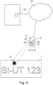
- Figure 1 shows a section of a first embodiment of a system 100 according to the invention, which is intended for detecting manipulation of an object that is marked with a graphic representation of information.
- the manipulation can relate to both the object itself and the information arranged on the object.
- the object which in the exemplary embodiment is a vehicle license plate 1, is marked with a graphic representation of the information in the form of a data matrix code 10.
- the data matrix code 10 forms light and dark areas 11, which are referred to as modules.
- the data matrix code 10 arranged on the license plate 1 encodes a serial number of the circuit board of the vehicle license plate 1.
- the vehicle license plate 1 is made retroreflective by means of a glass bead-based film.
- a glass bead-based film Such films are based on a large number of transparent and white-colored (so-called blind) glass beads, the Diameter is typically in the range between ten and 100 ⁇ m, which are arranged in a common plane parallel to the plane of the license plate plate and embedded in a transparent binder layer.
- the transparent binder layer is mirrored on the back by means of a thin metal layer, for example made of aluminum or silver.
- Such glass bead-based retroreflective films are widely known from the prior art.
- the glass beads embedded in the film are arranged irregularly to a certain extent, and on the other hand, the spatial distribution of transparent and blind glass beads is random and thus highly irregular. This means that the vehicle license plate 1 has a surface on its retroreflective side with an irregular microstructure that provides sufficient contrast. The contrast of the microstructure is further deepened by laser inscription on the film.
- the data matrix code 10 is introduced into the material of the retroreflective film by means of laser marking.
- the system 100 according to the invention has two functional units 40, 70 that are designed separately from one another.
- a first functional unit 40 is intended for carrying out product registration. It is in Figure 1 It is designed as a stationary unit and is intended to be arranged preferably spatially adjacent to or in the production facility in which the object marked with the graphic representation of the information, ie the vehicle license plate 1, is manufactured.
- the first functional unit 40 comprises a separately designed first camera 42, which is in data connection with the first functional unit 40 and is designed to take a picture of the surface area of the license plate 1 in which the graphic representation of the information, ie the data matrix code 10, wherein the resolution of the camera 42 is sufficient to resolve the irregular microstructure produced by the glass beads embedded in the retroreflective film.
- the first functional unit 40 comprises a first analysis unit 44, which is set up to analyze images taken by the first camera 42 of the surface area of the license plate 1, in which the graphic representation of the information, i.e. the data matrix code 10 is arranged, in the light and/or dark areas 11 in a spatially resolved manner in order to generate a first identifier, the so-called reference identifier, which is directly and unambiguously linked to the registered vehicle license plate 1.
- a first analysis unit 44 which is set up to analyze images taken by the first camera 42 of the surface area of the license plate 1, in which the graphic representation of the information, i.e. the data matrix code 10 is arranged, in the light and/or dark areas 11 in a spatially resolved manner in order to generate a first identifier, the so-called reference identifier, which is directly and unambiguously linked to the registered vehicle license plate 1.
- the first functional unit 40 comprises a data structure 50 in which at least one identifier can be provided.
- This is designed as a database that can be accessed by a suitably designed reading device via a network, e.g. the Internet 101, in order to at least read data stored in the database, in particular reference identifiers.
- the database is stored on a server connected to the Internet 101 and can be accessed from virtually anywhere in the world.
- the data structure 50 is designed such that during product registration, the reference identifier can be linked to the information encoded in the graphical representation when it is stored in the data structure 50 in such a way that the linked reference identifier can be retrieved from the data structure 50 by specifying the information.
- the second functional unit 70 is intended for carrying out product validation in the field, i.e. for checking the authenticity of a vehicle license plate that is usually mounted on a motor vehicle.
- the second functional unit 70 is designed as a handheld device, which is suitable for being carried at all times by a person entrusted with checking vehicle license plates.
- the second functional unit 70 has a second camera 72 which is integrated into the housing of the second functional unit 70 and, like the first camera 42, is designed to create a picture of the surface area of the license plate 1 in which the graphic representation of the information, i.e. the data matrix code 10, is arranged, wherein the resolution of the second camera 72 is also sufficient to resolve the irregular microstructure.
- a second camera 72 which is integrated into the housing of the second functional unit 70 and, like the first camera 42, is designed to create a picture of the surface area of the license plate 1 in which the graphic representation of the information, i.e. the data matrix code 10, is arranged, wherein the resolution of the second camera 72 is also sufficient to resolve the irregular microstructure.
- the second functional unit 70 has a second analysis unit 74, which is set up to analyze images taken by the second camera 72 of the surface area of the license plate in which the graphic representation of the information is arranged in the light and/or dark areas 11 in a spatially resolved manner in order to generate a second identifier, a "test identifier".
- a second analysis unit 74 which is set up to analyze images taken by the second camera 72 of the surface area of the license plate in which the graphic representation of the information is arranged in the light and/or dark areas 11 in a spatially resolved manner in order to generate a second identifier, a "test identifier".
- the second testing unit 70 further comprises a decoding unit 76 which is designed to extract the information encoded therein from a recording, taken by the second camera 72, of the surface area of the license plate 1 in which the graphic representation of the information is arranged.
- the second test unit 70 is also set up to make the information extracted by the decoding unit 76 available for further processing.
- the second test unit 70 forms a suitable interface for data communication, e.g. via near field communication, WiFi, BlueTooth ® or via a mobile network. IP-based communication is possible via at least one of these interfaces, in particular for access to the Internet 101.
- the second functional unit 70 comprises a means for retrieving an identifier 78 from the data structure 50.
- This means 78 is set up to specifically retrieve the one reference identifier from the data structure 50, which is stored in the data structure 50 together with the information that is encoded in the graphic identification and stored on the license plate 1.
- the second functional unit 70 also includes a comparison unit 80 which is configured to carry out a method for determining the degree of agreement between two identifiers, which are a reference identifier retrieved from the data structure 50 and the check identifier generated by means of the second functional unit 70.
- the analysis unit 44, 74, the decoding unit 76, the comparison unit 80 and the categorization unit 82 are implemented in software.
- the associated software is executed on a CPU, which in the second functional unit 70 is arranged together with the second camera 72 in a common housing.
- the second functional unit 70 is designed as a smartphone.
- the result determined by the categorization unit 82 is visually displayed on the display 84 of the smartphone.
- At least the second functional unit 70 has position correction means 86. These are designed to carry out a position correction of the image to be analyzed during the spatially resolved analysis of an image of the surface area of the license plate 1 in which the graphic representation of the information is arranged.
- the position correction means 86 are configured to carry out a position correction based on at least a subset of the light and/or dark areas 11 of the data matrix code 10 located on the license plate 1.
- the second functional unit 70 also has size correction means 88. These are designed to carry out a size correction of the image to be analyzed during the spatially resolved analysis of the test image in the bright and/or dark areas 11.
- the position correction means 86 and size correction means 88 provided in the second functional unit 70 serve to ensure that the position and size of the data matrix code 10 are the same in both the reference image and the test image. In the system 1 shown, it is therefore provided to carry out a registration of the reference image and the test image.
- both analysis units 44, 74 are set up to break down the light and/or dark areas 11 forming the data matrix code 10, which are also referred to as modules, into a predetermined number of subsections during the spatially resolved analysis of a recording of the surface area of the license plate in which the data matrix code 10 is arranged, created by one of the cameras 42, 72.
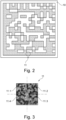
- a data matrix code basically consists of a structure of n ⁇ n squares, which can be light or dark.
- a data matrix code 10 in accordance with this exemplary embodiment is in Fig. 2 shown as an example.
- the data matrix code 10 has 10 ⁇ 10 modules 11. In the embodiment shown, each of these modules 11 is again regularly divided into four square sections 11.1 - 11.4. Each of these square sections 11.1 - 11.4 is assigned a unique identifier.
- Figure 3 shows an arbitrarily selected, dark colored module 11 of the Data Matrix code from Figure 2 .
- Both analysis units 44, 74 are set up to assign a brightness value to the respective analyzed sections 11.1 - 11.4.
- the resolution of the brightness values is 8 bits.
- the identifiers generated by the analysis units 44, 74 are based on the unique identification of the square sections 11.1 - 11.4 and the brightness values assigned to the respective sections.
- the following process steps, which serve the purpose of product validation, are carried out at a later stage in order to check a license plate 1', which is at least at first glance identical to the license plate 1 marked with the graphical representation of the information in the first steps, to see whether it is actually the license plate 1' identified in the context of the product registration or whether the license plate 1' is marked with the information that was already on the registered license plate 1 during product registration.
- the procedure only delivers a positive test result if the validated license plate 1' is actually the registered license plate and if the product validation shows that the information with which the validated license plate 1' is marked is identical to the information present on the registered license plate 1 in the registration step.
- the result of the categorization is presented to a user on the display 84 of the mobile phone.
- the reference identifier is stored together with the information in the data structure 50 during product registration.
- the reference identifier is retrieved from the data structure 50 using the information. This procedure allows an identifier stored in the data structure 50 that is assigned to the object 1 to be validated to be retrieved in a resource-saving manner. In this way, the method for determining the degree of agreement between the test identifier and the reference identifier retrieved from the data structure 50 only needs to be carried out once.
- both a position correction and a size correction of the image to be analyzed are carried out in order to achieve image registration between the reference image and the test image.
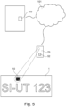
- FIG. 1 and 5 A second embodiment of a system 1 according to the invention is shown. Its structure corresponds in large parts to that of the system according to the first embodiment. Corresponding features are designated with corresponding reference numerals.
- the first functional unit 40 of the system according to the second embodiment is identical to the first functional unit 40 of the system according to the first embodiment.
- the second functional unit 70 of the system according to the second embodiment differs from the second functional unit 70 of the system according to the first embodiment, although it has an otherwise identical structure, in that the second functional unit 70 does not require permanent access to the data structure 50 accessible via the Internet 101 in order to function properly.
- a data structure 52 is arranged on the second functional unit 70, which represents a complete copy of the data structure 50.
- the data structure 50 is not accessed, but rather the locally stored data structure 52.
Landscapes
- Engineering & Computer Science (AREA)
- General Physics & Mathematics (AREA)
- Physics & Mathematics (AREA)
- Health & Medical Sciences (AREA)
- General Health & Medical Sciences (AREA)
- Theoretical Computer Science (AREA)
- Toxicology (AREA)
- Multimedia (AREA)
- Computer Vision & Pattern Recognition (AREA)
- Computer Security & Cryptography (AREA)
- Artificial Intelligence (AREA)
- Computing Systems (AREA)
- Databases & Information Systems (AREA)
- Evolutionary Computation (AREA)
- Medical Informatics (AREA)
- Software Systems (AREA)
- Credit Cards Or The Like (AREA)
- Image Analysis (AREA)
Claims (15)
- Procédure de détection de la manipulation ou de la contrefaçon d'un objet (1), à l'aide d'un système selon la revendication 9, dans lequel l'objet est marqué avec une représentation graphique d'une information, dans lequel la représentation graphique de l'information forme des zones claires et sombres (11) et l'objet (1) présente une surface présentant une microstructure irrégulière et contrastée, comportant les étapes de processus consistant à :a. créer un premier enregistrement de la surface d'un objet (1) à enregistrer, dans lequel la représentation graphique des informations est placée,b. fournir un identifiant de référence généré à partir du premier enregistrement dans une structure de données (50),c. créer un deuxième enregistrement de la surface d'un objet (1') à valider, dans lequel la représentation graphique de l'information est placée, dans lequel tant l'objet (1') que l'information sont au moins apparemment identiques à l'objet enregistré (1) aux étapes a. et b. ou les informations qui y sont placées,d. récupérer un identifiant de référence à partir de la structure de données (50), ete. exécuter une procédure pour déterminer le degré de concordance entre un identifiant de test généré à partir du deuxième enregistrement et l'identifiant de référence extrait de la structure de données, dans lequel pour générer l'identifiant de référence et l'identifiant de test les étapes de procédés suivantes sont exécutées :f. analyse spatialement résolue du premier enregistrement dans les zones claires et/ou sombres (11) et génération d'un identifiant de référence,g. analyse spatialement résolue de la deuxième image de la surface dans les zones claires et/ou sombres (11') et génération d'un identifiant de test,dans lequel le procédé est caractérisé en ce que la surface de l'objet est recouverte d'un film rétroréfléchissant à base de billes de verre qui forme la microstructure irrégulière, dans lequel la représentation graphique de l'information est disposée sur l'objet de telle sorte que la microstructure irrégulière soit délimitée par la représentation graphique de l'information.
- Procédé selon la revendication 1, caractérisé par les étapes de procédé supplémentaires suivantes :
h. catégoriser l'élément à valider (1') commei. « non manipulé » si au moins un degré de concordance minimum prédéfini est atteint, ouii. « manipulé » si un degré de concordance minimum n'est pas atteint. - Procédé selon la revendication 1, caractérisé en ce que dans une étape précédente du procédé, l'objet (1) est marqué d'une représentation graphique de l'information, dans lequel la représentation graphique des informations forme des zones claires et sombres (11) .
- Procédé selon la revendication 1, caractérisé en ce quea. l'identifiant de référence est mémorisé avec les informations dans la structure de données (50), et en ce queb. l'identifiant de référence à l'étape i. est récupéré sur la base des informations provenant de la structure de données (50).
- Procédé selon la revendication 1, caractérisé par l'étape supplémentaire suivante :a. extraire les informations codées dans la représentation graphique des informations, etb. fournir les informations extraites en vue d'un traitement ultérieur.
- Procédé selon la revendication 1, caractérisé en ce que l'objet (1) est un document d'identification, un moyen de paiement ou est une plaque d'immatriculation de véhicule.
- Procédé selon la revendication 1, caractérisé en ce que lors de l'analyse du premier ou du deuxième enregistrement de manière spatialement résolue, une correction de position et/ou une correction de taille de l'enregistrement à analyser est effectuée dans les zones claires et/ou sombres (11, 11').
- Procédé selon la revendication 1, caractérisé en ce que lors de l'analyse du premier ou du deuxième enregistrement de manière spatialement résolue dans les zones claires et/ou sombres (11, 11'), les zones claires et/ou sombres analysées sont divisées en un nombre prédéterminé de sections partielles (11.1-11.4, 11.1'-11.4').
- Système (100) de contrôle d'une identification infalsifiable d'un objet (1, 1') avec information, dans lequel l'objet (1, 1') est marqué avec une représentation graphique d'une information, notamment sous la forme d'un code-barres, d'un code QR ou d'un code Data Matrix (10, 10') pour former des zones claires et sombres (11, 11'), et l'objet (1, 1) présente une surface avec une microstructure irrégulière, contrastée, dans lequel le système (100) comporte les composants suivants :a. une caméra (42, 72) adaptée pour créer un enregistrement de la surface de l'objet (1, 1') dans laquelle la représentation graphique des informations est placée, dans lequel la résolution de la caméra (42, 72) est suffisante pour résoudre la microstructure irrégulière,b. une structure de données (50, 52) dans laquelle au moins un identifiant peut être fourni,c. une unité de décodage (76), qui est configurée pour extraire les informations d'un enregistrement créé par la caméra (42, 72) de la surface de l'objet (1, 1'), dans laquelle la représentation graphique des informations est placée, et pour la fournir en vue d'un traitement ultérieur,d. une unité de comparaison (80) qui est configurée pour fournir un procédé permettant de déterminer le degré de concordance entre deux enregistrements différents de la surface de l'objet (1, 1'), dans laquelle la représentation graphique des informations est placée, pour exécuter les identifiants générés,e. une unité d'analyse (44, 74) qui est configurée pour effectuer une analyse spatialement résolue des enregistrements créés par la caméra de la surface de l'objet (1, 1'), dans laquelle la représentation graphique des informations est placée, dans les zones claires et/ou sombres (11, 11') et générer un identifiant, caractérisé en ce que la surface de l'objet (1, 1') est recouverte d'un film rétroréfléchissant à base de billes de verre, qui forme le microstructure irrégulière, la représentation graphique de l'information étant disposée sur l'objet de telle manière que la microstructure irrégulière soit délimitée par la représentation graphique de l'information.
- Système (100) selon la revendication 9, caractérisé en ce qu'il comprend en outre une unité de catégorisation (82) qui est configurée pour catégoriser les informations extraites en fonction du résultat du procédé effectué par l'unité de comparaison (80) comme suit :i. « non manipulé » si au moins un degré de concordance minimum prédéfini est atteint, ouii. « manipulé » si un degré de concordance minimum n'est pas atteint.
- Système (100) selon la revendication 9, caractérisé en ce que le système (100) comprend en outre des moyens pour récupérer un identifiant à partir de la structure de données (50, 52).
- Système (100) selon la revendication 9, caractérisé en ce que la structure de données (50, 52) est établie de telle sorte qu'un identifiant puisse être mémorisé avec les informations dans la structure de données (50, 52).
- Système (100) selon la revendication 9, caractérisé en ce que l'objet (1) est un document d'identification, un moyen de paiement ou une plaque d'immatriculation d'un véhicule.
- Système (100) selon la revendication 9, caractérisé en ce que le système présente :a. des moyens de correction de position (86) conçus pour, lors de l'analyse spatialement résolue d'un enregistrement de la surface de l'objet (1, 1'), dans laquelle la représentation graphique des informations est placée, effectuer une correction de position de l'enregistrement à analyser, et/oub. des moyens de correction de taille (88), qui sont conçus pour lors de l'analyse spatialement résolue d'un enregistrement de la surface de l'objet (1, 1'), dans laquelle la représentation graphique des informations est placée, effectuer une correction de taille de l'enregistrement à analyser.
- Système (100) selon la revendication 9, caractérisé en ce que l'unité d'analyse (44, 74) est configurée, lors de l'analyse spatialement résolue d'un enregistrement créé par la caméra (42, 72) de la surface de l'objet (1, 1'), dans laquelle la représentation graphique des informations est placée, pour diviser les zones claires et/ou sombres analysées (11, 11') en un nombre prédéterminé de sections partielles (11.1-11.4, 11.1'-11.4').
Applications Claiming Priority (2)
| Application Number | Priority Date | Filing Date | Title |
|---|---|---|---|
| DE102020124060.0A DE102020124060A1 (de) | 2020-09-15 | 2020-09-15 | Verfahren zur Feststellung einer Manipulation oder Fälschung eines Gegenstands sowie System hierzu |
| PCT/EP2021/075255 WO2022058319A1 (fr) | 2020-09-15 | 2021-09-14 | Procédé de détection d'une manipulation ou d'une contrefaçon d'un objet et système correspondant |
Publications (3)
| Publication Number | Publication Date |
|---|---|
| EP4214689A1 EP4214689A1 (fr) | 2023-07-26 |
| EP4214689C0 EP4214689C0 (fr) | 2024-07-31 |
| EP4214689B1 true EP4214689B1 (fr) | 2024-07-31 |
Family
ID=77924363
Family Applications (1)
| Application Number | Title | Priority Date | Filing Date |
|---|---|---|---|
| EP21777990.9A Active EP4214689B1 (fr) | 2020-09-15 | 2021-09-14 | Procédé de détection d'une manipulation ou d'une contrefaçon d'un objet et système correspondant |
Country Status (5)
| Country | Link |
|---|---|
| US (1) | US20230394856A1 (fr) |
| EP (1) | EP4214689B1 (fr) |
| DE (1) | DE102020124060A1 (fr) |
| PL (1) | PL4214689T3 (fr) |
| WO (1) | WO2022058319A1 (fr) |
Citations (1)
| Publication number | Priority date | Publication date | Assignee | Title |
|---|---|---|---|---|
| EP2724332B1 (fr) * | 2011-06-23 | 2018-04-18 | Covectra, Inc. | Systèmes de suivi et d'authentification de produits |
Family Cites Families (13)
| Publication number | Priority date | Publication date | Assignee | Title |
|---|---|---|---|---|
| US5237164A (en) | 1989-05-12 | 1993-08-17 | Sony Corporation | Card having retroreflective bar codes and a magnetic stripe |
| DE10304805A1 (de) | 2003-02-05 | 2004-08-19 | Informium Ag | Verfahren zur Herstellung von Sicherheitskennzeichen |
| US8301893B2 (en) * | 2003-08-13 | 2012-10-30 | Digimarc Corporation | Detecting media areas likely of hosting watermarks |
| DE602005014755D1 (de) * | 2004-03-12 | 2009-07-16 | Ingenia Technology Ltd | Verfahren und vorrichtungen zur erzeugung authentifizierbarer gegenstände und ihrer nachfolgenden überprüfung |
| US20090080760A1 (en) | 2007-09-21 | 2009-03-26 | Microsecurity Lab Inc. | Anti-counterfeiting mark and methods |
| KR101204810B1 (ko) * | 2008-04-30 | 2012-11-26 | 교도 인사쯔 가부시키가이샤 | 재귀 반사체 라벨 시트 및 재귀 반사체 라벨 시트가 고착된 물품 |
| EP2831815A1 (fr) | 2012-03-30 | 2015-02-04 | 3M Innovative Properties Company | Articles rétro-réfléchissants comportant un code lisible par machine |
| CN107924470A (zh) * | 2015-08-21 | 2018-04-17 | 3M创新有限公司 | 增加设置在光学活性制品上的字符的相异性 |
| DE102015219400B4 (de) | 2015-10-07 | 2019-01-17 | Koenig & Bauer Ag | Verfahren zur Prüfung der Identität und/oder Echtheit eines Gegenstandes |
| CN106682912B (zh) | 2015-11-10 | 2021-06-15 | 艾普维真股份有限公司 | 3d结构的认证方法 |
| EP4296998A3 (fr) * | 2016-05-13 | 2024-02-28 | 3M Innovative Properties Company | Détection de contrefaçon d'un article optiquement actif à l'aide d'éléments de sécurité |
| DE102018108741A1 (de) | 2018-04-12 | 2019-10-17 | Klöckner Pentaplast Gmbh | Verfahren für optische Produktauthentifizierung |
| CN111091394A (zh) * | 2019-01-27 | 2020-05-01 | 海南亚元防伪技术研究所(普通合伙) | 产品防伪保险包装方法 |
-
2020
- 2020-09-15 DE DE102020124060.0A patent/DE102020124060A1/de active Pending
-
2021
- 2021-09-14 US US18/026,500 patent/US20230394856A1/en not_active Abandoned
- 2021-09-14 EP EP21777990.9A patent/EP4214689B1/fr active Active
- 2021-09-14 PL PL21777990.9T patent/PL4214689T3/pl unknown
- 2021-09-14 WO PCT/EP2021/075255 patent/WO2022058319A1/fr not_active Ceased
Patent Citations (1)
| Publication number | Priority date | Publication date | Assignee | Title |
|---|---|---|---|---|
| EP2724332B1 (fr) * | 2011-06-23 | 2018-04-18 | Covectra, Inc. | Systèmes de suivi et d'authentification de produits |
Also Published As
| Publication number | Publication date |
|---|---|
| EP4214689A1 (fr) | 2023-07-26 |
| EP4214689C0 (fr) | 2024-07-31 |
| DE102020124060A1 (de) | 2022-03-17 |
| PL4214689T3 (pl) | 2024-11-12 |
| WO2022058319A1 (fr) | 2022-03-24 |
| US20230394856A1 (en) | 2023-12-07 |
Similar Documents
| Publication | Publication Date | Title |
|---|---|---|
| EP2958086B1 (fr) | Procédé de contrôle d'un document de sécurité | |
| EP3746992B1 (fr) | Procédé pour le contrôle de l'authenticité et/ou de l'intégrité d'un document de sécurité comprenant une caractéristique de sécurité imprimée, caractéristique de sécurité et dispositif pour la vérification | |
| DE4311295A1 (de) | Identifikationssystem | |
| EP3424024B1 (fr) | Document de sécurite et procédé permettant d'authentifier ce document | |
| EP0040839A2 (fr) | Système d'identification pour véhicules à moteur, procédé et appareil pour la fabrication d'un tel système, et procédé et appareil pour restituer une information codée contenue dans un tel système | |
| DE10304805A1 (de) | Verfahren zur Herstellung von Sicherheitskennzeichen | |
| EP3074236B2 (fr) | Procédé de fabrication d'un marquage d'objet pour l'authentification optique | |
| DE10162537A1 (de) | Verfahren zur Authentizitätssicherung von Dokumenten | |
| EP2650140A1 (fr) | Elément de sécurité à feuille microperforé | |
| EP3133534B1 (fr) | Objet de valeur et systeme d'identification et de verification d'un objet de valeur | |
| EP4214689B1 (fr) | Procédé de détection d'une manipulation ou d'une contrefaçon d'un objet et système correspondant | |
| DE112021000421B4 (de) | Mechanisch eingepresste unverwechselbare merkmale zur echtheits- und herkunftsverfolgung | |
| EP2930699A1 (fr) | Caractéristique de sécurité comprenant une section de code et de marquage | |
| EP4215378A2 (fr) | Vérification d'un document de sécurité sur la base de morphologies de gouttelettes | |
| EP2769364B1 (fr) | Procédé de vérification d'un document de sécurité par une barrière visuelle à l'aide d'un dispositif d'affichage | |
| EP2394250B1 (fr) | Procédé et dispositif pour vérifier des documents par utilisation d'une transformation en ondelettes | |
| EP3922473B1 (fr) | Procédé de production d'une image imprimée sur un support de données pour un document de sécurité ou de valeur | |
| EP3185221B1 (fr) | Dispositif d'authentification et procede de reconnaissance optique ou acoustique | |
| EP2138322B1 (fr) | Document de valeur ou de sécurité doté d'une caractéristique de sécurité | |
| EP3548300B1 (fr) | Procédé de fabrication et de vérification d'un document de sécurité et document de sécurité | |
| DE102023115512A1 (de) | Sicherheitsdokument-verifizierungsvorrichtung und verfahren zum prüfen eines sicherheitsdokuments | |
| WO2017055422A1 (fr) | Procédé et dispositif d'authentification d'un objet ou d'une personne via un élément de sécurité modulaire | |
| DE102023135932A1 (de) | Verfahren zur Verifikation von Sicherheitsdokumenten | |
| DE102022130970A1 (de) | Verfahren zur Herstellung und Verifizierung eines individualisierten Sicherheitsdokuments | |
| DE102020215403A1 (de) | Verfahren zur Prüfung der Herkunft und/oder Identität eines Produkts |
Legal Events
| Date | Code | Title | Description |
|---|---|---|---|
| STAA | Information on the status of an ep patent application or granted ep patent |
Free format text: STATUS: UNKNOWN |
|
| STAA | Information on the status of an ep patent application or granted ep patent |
Free format text: STATUS: THE INTERNATIONAL PUBLICATION HAS BEEN MADE |
|
| PUAI | Public reference made under article 153(3) epc to a published international application that has entered the european phase |
Free format text: ORIGINAL CODE: 0009012 |
|
| STAA | Information on the status of an ep patent application or granted ep patent |
Free format text: STATUS: REQUEST FOR EXAMINATION WAS MADE |
|
| 17P | Request for examination filed |
Effective date: 20230328 |
|
| AK | Designated contracting states |
Kind code of ref document: A1 Designated state(s): AL AT BE BG CH CY CZ DE DK EE ES FI FR GB GR HR HU IE IS IT LI LT LU LV MC MK MT NL NO PL PT RO RS SE SI SK SM TR |
|
| DAV | Request for validation of the european patent (deleted) | ||
| DAX | Request for extension of the european patent (deleted) | ||
| GRAP | Despatch of communication of intention to grant a patent |
Free format text: ORIGINAL CODE: EPIDOSNIGR1 |
|
| STAA | Information on the status of an ep patent application or granted ep patent |
Free format text: STATUS: GRANT OF PATENT IS INTENDED |
|
| INTG | Intention to grant announced |
Effective date: 20240319 |
|
| GRAS | Grant fee paid |
Free format text: ORIGINAL CODE: EPIDOSNIGR3 |
|
| GRAA | (expected) grant |
Free format text: ORIGINAL CODE: 0009210 |
|
| STAA | Information on the status of an ep patent application or granted ep patent |
Free format text: STATUS: THE PATENT HAS BEEN GRANTED |
|
| AK | Designated contracting states |
Kind code of ref document: B1 Designated state(s): AL AT BE BG CH CY CZ DE DK EE ES FI FR GB GR HR HU IE IS IT LI LT LU LV MC MK MT NL NO PL PT RO RS SE SI SK SM TR |
|
| REG | Reference to a national code |
Ref country code: CH Ref legal event code: EP Ref country code: GB Ref legal event code: FG4D Free format text: NOT ENGLISH |
|
| REG | Reference to a national code |
Ref country code: DE Ref legal event code: R096 Ref document number: 502021004616 Country of ref document: DE |
|
| REG | Reference to a national code |
Ref country code: IE Ref legal event code: FG4D Free format text: LANGUAGE OF EP DOCUMENT: GERMAN |
|
| U01 | Request for unitary effect filed |
Effective date: 20240731 |
|
| U07 | Unitary effect registered |
Designated state(s): AT BE BG DE DK EE FI FR IT LT LU LV MT NL PT SE SI Effective date: 20240806 |
|
| U20 | Renewal fee for the european patent with unitary effect paid |
Year of fee payment: 4 Effective date: 20241028 |
|
| PG25 | Lapsed in a contracting state [announced via postgrant information from national office to epo] |
Ref country code: NO Free format text: LAPSE BECAUSE OF FAILURE TO SUBMIT A TRANSLATION OF THE DESCRIPTION OR TO PAY THE FEE WITHIN THE PRESCRIBED TIME-LIMIT Effective date: 20241031 |
|
| PG25 | Lapsed in a contracting state [announced via postgrant information from national office to epo] |
Ref country code: GR Free format text: LAPSE BECAUSE OF FAILURE TO SUBMIT A TRANSLATION OF THE DESCRIPTION OR TO PAY THE FEE WITHIN THE PRESCRIBED TIME-LIMIT Effective date: 20241101 |
|
| PG25 | Lapsed in a contracting state [announced via postgrant information from national office to epo] |
Ref country code: IS Free format text: LAPSE BECAUSE OF FAILURE TO SUBMIT A TRANSLATION OF THE DESCRIPTION OR TO PAY THE FEE WITHIN THE PRESCRIBED TIME-LIMIT Effective date: 20241130 |
|
| PG25 | Lapsed in a contracting state [announced via postgrant information from national office to epo] |
Ref country code: HR Free format text: LAPSE BECAUSE OF FAILURE TO SUBMIT A TRANSLATION OF THE DESCRIPTION OR TO PAY THE FEE WITHIN THE PRESCRIBED TIME-LIMIT Effective date: 20240731 |
|
| PG25 | Lapsed in a contracting state [announced via postgrant information from national office to epo] |
Ref country code: ES Free format text: LAPSE BECAUSE OF FAILURE TO SUBMIT A TRANSLATION OF THE DESCRIPTION OR TO PAY THE FEE WITHIN THE PRESCRIBED TIME-LIMIT Effective date: 20240731 Ref country code: RS Free format text: LAPSE BECAUSE OF FAILURE TO SUBMIT A TRANSLATION OF THE DESCRIPTION OR TO PAY THE FEE WITHIN THE PRESCRIBED TIME-LIMIT Effective date: 20241031 |
|
| PG25 | Lapsed in a contracting state [announced via postgrant information from national office to epo] |
Ref country code: RS Free format text: LAPSE BECAUSE OF FAILURE TO SUBMIT A TRANSLATION OF THE DESCRIPTION OR TO PAY THE FEE WITHIN THE PRESCRIBED TIME-LIMIT Effective date: 20241031 Ref country code: NO Free format text: LAPSE BECAUSE OF FAILURE TO SUBMIT A TRANSLATION OF THE DESCRIPTION OR TO PAY THE FEE WITHIN THE PRESCRIBED TIME-LIMIT Effective date: 20241031 Ref country code: IS Free format text: LAPSE BECAUSE OF FAILURE TO SUBMIT A TRANSLATION OF THE DESCRIPTION OR TO PAY THE FEE WITHIN THE PRESCRIBED TIME-LIMIT Effective date: 20241130 Ref country code: HR Free format text: LAPSE BECAUSE OF FAILURE TO SUBMIT A TRANSLATION OF THE DESCRIPTION OR TO PAY THE FEE WITHIN THE PRESCRIBED TIME-LIMIT Effective date: 20240731 Ref country code: GR Free format text: LAPSE BECAUSE OF FAILURE TO SUBMIT A TRANSLATION OF THE DESCRIPTION OR TO PAY THE FEE WITHIN THE PRESCRIBED TIME-LIMIT Effective date: 20241101 Ref country code: ES Free format text: LAPSE BECAUSE OF FAILURE TO SUBMIT A TRANSLATION OF THE DESCRIPTION OR TO PAY THE FEE WITHIN THE PRESCRIBED TIME-LIMIT Effective date: 20240731 |
|
| PG25 | Lapsed in a contracting state [announced via postgrant information from national office to epo] |
Ref country code: SM Free format text: LAPSE BECAUSE OF FAILURE TO SUBMIT A TRANSLATION OF THE DESCRIPTION OR TO PAY THE FEE WITHIN THE PRESCRIBED TIME-LIMIT Effective date: 20240731 |
|
| PG25 | Lapsed in a contracting state [announced via postgrant information from national office to epo] |
Ref country code: MC Free format text: LAPSE BECAUSE OF FAILURE TO SUBMIT A TRANSLATION OF THE DESCRIPTION OR TO PAY THE FEE WITHIN THE PRESCRIBED TIME-LIMIT Effective date: 20240731 |
|
| PG25 | Lapsed in a contracting state [announced via postgrant information from national office to epo] |
Ref country code: CZ Free format text: LAPSE BECAUSE OF FAILURE TO SUBMIT A TRANSLATION OF THE DESCRIPTION OR TO PAY THE FEE WITHIN THE PRESCRIBED TIME-LIMIT Effective date: 20240731 |
|
| PG25 | Lapsed in a contracting state [announced via postgrant information from national office to epo] |
Ref country code: SK Free format text: LAPSE BECAUSE OF FAILURE TO SUBMIT A TRANSLATION OF THE DESCRIPTION OR TO PAY THE FEE WITHIN THE PRESCRIBED TIME-LIMIT Effective date: 20240731 |
|
| REG | Reference to a national code |
Ref country code: CH Ref legal event code: PL |
|
| PLBE | No opposition filed within time limit |
Free format text: ORIGINAL CODE: 0009261 |
|
| STAA | Information on the status of an ep patent application or granted ep patent |
Free format text: STATUS: NO OPPOSITION FILED WITHIN TIME LIMIT |
|
| 26N | No opposition filed |
Effective date: 20250501 |
|
| PG25 | Lapsed in a contracting state [announced via postgrant information from national office to epo] |
Ref country code: CH Free format text: LAPSE BECAUSE OF NON-PAYMENT OF DUE FEES Effective date: 20240930 |
|
| PG25 | Lapsed in a contracting state [announced via postgrant information from national office to epo] |
Ref country code: IE Free format text: LAPSE BECAUSE OF NON-PAYMENT OF DUE FEES Effective date: 20240914 |
|
| PGFP | Annual fee paid to national office [announced via postgrant information from national office to epo] |
Ref country code: PL Payment date: 20250829 Year of fee payment: 5 |
|
| U20 | Renewal fee for the european patent with unitary effect paid |
Year of fee payment: 5 Effective date: 20250923 |
|
| PG25 | Lapsed in a contracting state [announced via postgrant information from national office to epo] |
Ref country code: RO Free format text: LAPSE BECAUSE OF FAILURE TO SUBMIT A TRANSLATION OF THE DESCRIPTION OR TO PAY THE FEE WITHIN THE PRESCRIBED TIME-LIMIT Effective date: 20240731 |
|
| PG25 | Lapsed in a contracting state [announced via postgrant information from national office to epo] |
Ref country code: CY Free format text: LAPSE BECAUSE OF FAILURE TO SUBMIT A TRANSLATION OF THE DESCRIPTION OR TO PAY THE FEE WITHIN THE PRESCRIBED TIME-LIMIT; INVALID AB INITIO Effective date: 20210914 |
|
| PG25 | Lapsed in a contracting state [announced via postgrant information from national office to epo] |
Ref country code: HU Free format text: LAPSE BECAUSE OF FAILURE TO SUBMIT A TRANSLATION OF THE DESCRIPTION OR TO PAY THE FEE WITHIN THE PRESCRIBED TIME-LIMIT; INVALID AB INITIO Effective date: 20210914 |