EP4227752A1 - Véhicule - Google Patents
Véhicule Download PDFInfo
- Publication number
- EP4227752A1 EP4227752A1 EP21877191.3A EP21877191A EP4227752A1 EP 4227752 A1 EP4227752 A1 EP 4227752A1 EP 21877191 A EP21877191 A EP 21877191A EP 4227752 A1 EP4227752 A1 EP 4227752A1
- Authority
- EP
- European Patent Office
- Prior art keywords
- tire
- vehicle
- distance
- travel route
- travel
- Prior art date
- Legal status (The legal status is an assumption and is not a legal conclusion. Google has not performed a legal analysis and makes no representation as to the accuracy of the status listed.)
- Granted
Links
Images



Classifications
-
- B—PERFORMING OPERATIONS; TRANSPORTING
- B62—LAND VEHICLES FOR TRAVELLING OTHERWISE THAN ON RAILS
- B62D—MOTOR VEHICLES; TRAILERS
- B62D6/00—Arrangements for automatically controlling steering depending on driving conditions sensed and responded to, e.g. control circuits
-
- G—PHYSICS
- G05—CONTROLLING; REGULATING
- G05D—SYSTEMS FOR CONTROLLING OR REGULATING NON-ELECTRIC VARIABLES
- G05D1/00—Control of position, course, altitude or attitude of land, water, air or space vehicles, e.g. using automatic pilots
- G05D1/02—Control of position or course in two dimensions
- G05D1/021—Control of position or course in two dimensions specially adapted to land vehicles
- G05D1/0212—Control of position or course in two dimensions specially adapted to land vehicles with means for defining a desired trajectory
-
- B—PERFORMING OPERATIONS; TRANSPORTING
- B62—LAND VEHICLES FOR TRAVELLING OTHERWISE THAN ON RAILS
- B62D—MOTOR VEHICLES; TRAILERS
- B62D6/00—Arrangements for automatically controlling steering depending on driving conditions sensed and responded to, e.g. control circuits
- B62D6/002—Arrangements for automatically controlling steering depending on driving conditions sensed and responded to, e.g. control circuits computing target steering angles for front or rear wheels
-
- B—PERFORMING OPERATIONS; TRANSPORTING
- B60—VEHICLES IN GENERAL
- B60W—CONJOINT CONTROL OF VEHICLE SUB-UNITS OF DIFFERENT TYPE OR DIFFERENT FUNCTION; CONTROL SYSTEMS SPECIALLY ADAPTED FOR HYBRID VEHICLES; ROAD VEHICLE DRIVE CONTROL SYSTEMS FOR PURPOSES NOT RELATED TO THE CONTROL OF A PARTICULAR SUB-UNIT
- B60W10/00—Conjoint control of vehicle sub-units of different type or different function
- B60W10/12—Conjoint control of vehicle sub-units of different type or different function including control of differentials
-
- B—PERFORMING OPERATIONS; TRANSPORTING
- B62—LAND VEHICLES FOR TRAVELLING OTHERWISE THAN ON RAILS
- B62D—MOTOR VEHICLES; TRAILERS
- B62D15/00—Steering not otherwise provided for
- B62D15/02—Steering position indicators ; Steering position determination; Steering aids
- B62D15/025—Active steering aids, e.g. helping the driver by actively influencing the steering system after environment evaluation
-
- B—PERFORMING OPERATIONS; TRANSPORTING
- B62—LAND VEHICLES FOR TRAVELLING OTHERWISE THAN ON RAILS
- B62D—MOTOR VEHICLES; TRAILERS
- B62D7/00—Steering linkage; Stub axles or their mountings
- B62D7/06—Steering linkage; Stub axles or their mountings for individually-pivoted wheels, e.g. on king-pins
- B62D7/14—Steering linkage; Stub axles or their mountings for individually-pivoted wheels, e.g. on king-pins the pivotal axes being situated in more than one plane transverse to the longitudinal centre line of the vehicle, e.g. all-wheel steering
- B62D7/15—Steering linkage; Stub axles or their mountings for individually-pivoted wheels, e.g. on king-pins the pivotal axes being situated in more than one plane transverse to the longitudinal centre line of the vehicle, e.g. all-wheel steering characterised by means varying the ratio between the steering angles of the steered wheels
-
- B—PERFORMING OPERATIONS; TRANSPORTING
- B62—LAND VEHICLES FOR TRAVELLING OTHERWISE THAN ON RAILS
- B62D—MOTOR VEHICLES; TRAILERS
- B62D7/00—Steering linkage; Stub axles or their mountings
- B62D7/06—Steering linkage; Stub axles or their mountings for individually-pivoted wheels, e.g. on king-pins
- B62D7/14—Steering linkage; Stub axles or their mountings for individually-pivoted wheels, e.g. on king-pins the pivotal axes being situated in more than one plane transverse to the longitudinal centre line of the vehicle, e.g. all-wheel steering
- B62D7/15—Steering linkage; Stub axles or their mountings for individually-pivoted wheels, e.g. on king-pins the pivotal axes being situated in more than one plane transverse to the longitudinal centre line of the vehicle, e.g. all-wheel steering characterised by means varying the ratio between the steering angles of the steered wheels
- B62D7/159—Steering linkage; Stub axles or their mountings for individually-pivoted wheels, e.g. on king-pins the pivotal axes being situated in more than one plane transverse to the longitudinal centre line of the vehicle, e.g. all-wheel steering characterised by means varying the ratio between the steering angles of the steered wheels characterised by computing methods or stabilisation processes or systems, e.g. responding to yaw rate, lateral wind, load, road condition
Definitions
- the present disclosure relates to a vehicle that travels on a preset travel route.
- Vehicles that travel on preset travel routes include vehicles configured to set a different steering angle for each of a plurality of tires to enable complex movement on the site (see, for example, JP 2010-20515 A (PTL 1)).
- a vehicle configured to travel on a preset travel route, comprising: a plurality of tires including a first tire and a second tire, and each configured to be set at a different steering angle; and a processing device configured to set a steering angle of each of the plurality of tires, wherein the processing device is configured to: when the vehicle deviates from the travel route and returns to the travel route, determine a return position on the travel route, and calculate a target position of the first tire and a target position of the second tire that allow the vehicle to travel on the travel route when located at the return position; find a common central point at which a difference between a distance from a current position of the first tire and a distance from the target position of the first tire is within a predetermined range and a difference between a distance from a current position of the second tire and a distance from the target position of the second tire is within a predetermined range; and set the steering angle of each of the plurality of tires so that the tire will be oriented in a
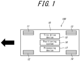
- FIG. 1 is a schematic plan view of the vehicle 100.
- the vehicle 100 travels on a preset travel route.
- the vehicle 100 may be configured to travel autonomously on the travel route, or configured to travel partially manually (for example, manually only during acceleration/deceleration and otherwise autonomously) on the travel route.
- the vehicle 100 includes a vehicle body 10, a plurality of tires 11 to 14, a tire drive device 15, a positioning system 16, and a processing device 17.
- the vehicle body 10 is configured to be able to carry heavy objects.
- the vehicle body 10 has a substantially rectangular shape in a plan view.
- the vehicle 100 travels in the longitudinal direction of the vehicle body 10 with one longitudinal end of the vehicle body 10 in front.
- the left end of the vehicle body 10 in the drawing is in front, and the vehicle 100 travels leftward in the drawing (see the arrow).
- the use, shape, and direction of travel of the vehicle body 10 are not limited to such.
- the plurality of tires 11 to 14 include a first tire 11 corresponding to the right front wheel, a second tire 12 corresponding to the left front wheel, a third tire 13 corresponding to the right rear wheel, and a fourth tire 14 corresponding to the left rear wheel.
- the arrangement of the tires 11 to 14 is, however, not limited to such.
- the number of tires included in the vehicle 100 is not limited to four.
- the tire drive device 15 rotates the tires 11 to 14 and sets their steering angles (i.e. the angles of the tires 11 to 14 with respect to the vehicle body 10).
- the tire drive device 15 in this embodiment can set a different rotation speed and steering angle for each of the tires 11 to 14.
- the tire drive device 15 may rotate the tires 11 to 14 using an internal combustion engine, or rotate the tires 11 to 14 using an electric motor.
- the steering angle of each of the tires 11 to 14 is feedback-controlled based on the results of detection by a steering angle detection sensor.
- the positioning system 16 is a system that measures the current position (which is the center position of the vehicle body 10 in this example, but is not limited to such) and orientation of the vehicle body 10.
- the positioning system 16 in this embodiment includes a global navigation satellite system (GNSS) receivers in the front and rear parts of the vehicle body 10, and can measure the detailed positions of the front and rear parts of the vehicle body 10. Based on the positions of the front and rear parts of the vehicle body 10, the positioning system 16 calculates the current position and orientation of the vehicle body 10.
- the positioning system 16 may measure the current position and orientation of the vehicle body 10 by any method other than the above, such as using a camera.
- the positioning system 16 may include only one receiver that has two antennas.
- the positioning system 16 may include only one receiver, and calculate (obtain) the orientation of the vehicle body 10 based on the measured latest position of the vehicle body 10 and the position of the vehicle body 10 a predetermined time before the latest position.
- the processing device 17 includes a processor, a volatile memory, a nonvolatile memory, an I/O interface, and the like.
- the processing device 17 is electrically connected to the positioning system 16, and can acquire the current position and orientation of the vehicle body 10 from the positioning system 16.
- the processing device 17 is also electrically connected to the tire drive device 15, and can transmit a control signal to the tire drive device 15 to control the tire drive device 15 and set the rotation speed and steering angle of each of the tires 11 to 14.
- the nonvolatile memory in the processing device 17 stores data of the preset travel route of the vehicle 100, and data of a route return program.
- the processor in the processing device 17 performs computation using the volatile memory based on the route return program.
- the processing device 17 transmits a control signal to the tire drive device 15 based on the results of computation in the volatile memory.
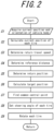
- FIG. 2 is a flowchart of the route return program.
- the route return program is a program for causing the vehicle 100 that has deviated from the travel route to return to the travel route, and is executed during travel on the travel route. The process illustrated in FIG. 2 is executed by the processing device 17.
- the processing device 17 acquires the current position and orientation of the vehicle body 10 (step S1).
- the current position and orientation of the vehicle body 10 can be acquired from the positioning system 16.
- the processing device 17 then calculates the current position of each of the tires 11 to 14 (step S2). Since the relative position of each of the tires 11 to 14 with respect to the vehicle body 10 is known, the current position of each of the tires 11 to 14 can be calculated based on the current position and orientation of the vehicle body 10.
- the processing device 17 determines the travel speed (hereinafter referred to as "return travel speed") when the vehicle 100 returns to the travel route (step S3).
- the return travel speed is determined based on the travel speed of the vehicle 100 during execution of a route travel program and conditions such as the weight of the load on the vehicle body 10. For example, if the load on the vehicle body 10 is light, the return travel speed may be set to be high. Alternatively, the return travel speed may be constant. Step S3 can be omitted in this case.
- the processing device 17 determines a reference distance (step S4).
- the reference distance is determined depending on the return travel speed determined in step S3. In this embodiment, the reference distance is determined to be longer when the return travel speed is higher, and shorter when the return travel speed is lower. The relationship between the return travel speed and the reference distance is, however, not limited to such.
- the processing device 17 determines the return position (step S5).
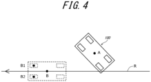
- the return position is determined based on the reference distance determined in step S4. Specifically, as illustrated in FIG. 3 , position B that is on travel route R and is reference distance L away from the current position A of the vehicle 100 is determined as the return position. The return position B is located ahead of the vehicle 100 in the direction of travel of the travel route R.
- the processing device 17 calculates the target position of the first tire 11 and the target position of the second tire 12 (step S6).
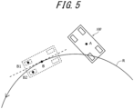
- the target position B 1 of the first tire 11 is such a position of the first tire 11 that allows the vehicle 100 to travel on the travel route R when located at the return position B.
- the target position B2 of the second tire 12 is such a position of the second tire 12 that allows the vehicle 100 to travel on the travel route R when located at the return position B.
- the respective positions of the first tire 11 and the second tire 12 when the vehicle body 10 is located at the return position B and the longitudinal direction (front-back direction) of the vehicle body 10 is parallel to the travel route R are the target position B1 of the first tire 11 and the target position B2 of the second tire 12 .
- the respective positions of the first tire 11 and the second tire 12 when the vehicle body 10 is located at the return position B and the longitudinal direction of the vehicle body 10 is parallel to the tangent to the travel route R are the target position B1 of the first tire 11 and the target position B2 of the second tire 12 .
- the processing device 17 finds a common central point (step S7).
- the common central point X is a point at which the distance from the current position A1 of the first tire 11 and the distance from the target position B1 of the first tire 11 are the same and the distance from the current position A2 of the second tire 12 and the distance from the target position B2 of the second tire 12 are the same. That is, the common central point X is the intersection point of the perpendicular bisector of the straight line connecting the current position A1 and the target position B1 of the first tire 11 and the perpendicular bisector of the straight line connecting the current position A2 and the target position B2 of the second tire 12.
- the processing device 17 sets the steering angle of each of the tires 11 to 14 (step S8). Specifically, as illustrated in FIG. 7 , the steering angle of the first tire 11 is set so that the first tire 11 will be oriented in the direction of the tangent to a clearance circle C1 whose center is the common central point X obtained in step S7 and whose radius is the distance from the current position A1 of the first tire 11 to the common central point X.
- each of the tires 12 to 14 other than the first tire 11 is set so that the tire will be oriented in the direction of the tangent to a corresponding one of clearance circles C2 to C4 whose center is the common central point X and whose radius is the distance from the current position of the tire to the common central point X.
- the processing device 17 then rotates the tires 11 to 14 toward the travel route of the vehicle 100 (step S9).
- the processing device 17 may rotate each of the tires 11 to 14 at the same rotation speed, or at a different rotation speed depending on the distance from the current position to the target position of the tire. For example, a tire for which the distance from the current position to the target position is long may be rotated at a higher rotation speed than a tire for which the distance from the current position to the target position is short.
- step S9 the processing device 17 returns to step S1, and repeats steps S1 to S9 until the vehicle 100 returns to the travel route.
- the processing device 17 constantly updates the return position (step S5) and constantly updates the set steering angle of each of the tires 11 to 14 according to the updated return position (step S8) until the vehicle 100 that has deviated from the travel route returns to the travel route.
- Steps S1 to S8 may be executed while rotating the tires 11 to 14 (i.e. during execution of step S9). In such a case, as the vehicle 100 approaches the travel route, the steering angle of each of the tires 11 to 14 is corrected so that the tire will be oriented in the direction along the travel route. Consequently, upon reaching the return position, the vehicle 100 can immediately travel on the travel route.
- the set steering angle of each of the tires 11 to 14 may be maintained until the vehicle 100 returns to the travel route, without repeating steps S1 to S9. Even in this case, by adjusting the steering angle of each of the tires 11 to 14 so that the tire will be oriented in the direction of travel of the travel route after the vehicle 100 reaches the return position, the vehicle 100 can immediately travel on the travel route. That is, the vehicle 100 can quickly return to the travel route.
- the common central point is a point at which the distance from the current position of the first tire 11 and the distance from the target position of the first tire 11 are the same and the distance from the current position of the second tire 12 and the distance from the target position of the second tire 12 are the same (step S7).
- the common central point may be determined in consideration of the slippage, etc. of each of the tires 11 to 14. That is, the common central point may be a point at which the difference between the distance from the current position of the first tire 11 and the distance from the target position of the first tire 11 is within a predetermined range and the difference between the distance from the current position of the second tire 12 and the distance from the target position of the second tire 12 is within a predetermined range.
- the steering angle of each of the tires 11 to 14 is set so that the tire will be oriented in the direction of the tangent to a clearance circle whose center is the common central point and whose radius is the distance from the tire to the common central point (Step S8).
- the steering angle of each of the tires 11 to 14 may be set so that the tire will be oriented in a direction whose angle difference from the direction of the tangent to the clearance circle whose center is the common central point and whose radius is the distance from the tire to the common central point is within a predetermined range.
- the common central point is determined based on the current position and the target position of each of two tires, i.e. the first tire 11 and the second tire 12 (step S7, FIG. 6 ).
- the common central point may be determined based on the current position and the target position of each of three or more tires.
- the vehicle according to this embodiment is a vehicle configured to travel on a preset travel route, comprising: a plurality of tires including a first tire and a second tire, and each configured to be set at a different steering angle; and a processing device configured to set a steering angle of each of the plurality of tires, wherein the processing device is configured to: when the vehicle deviates from the travel route and returns to the travel route, determine a return position on the travel route, and calculate a target position of the first tire and a target position of the second tire that allow the vehicle to travel on the travel route when located at the return position; find a common central point at which a difference between a distance from a current position of the first tire and a distance from the target position of the first tire is within a predetermined range and a difference between a distance from a current position of the second tire and a distance from the target position of the second tire is within a predetermined range; and set the steering angle of each of the plurality of tires so that the tire will be oriented in a
- the vehicle according to this embodiment can quickly locate each tire at such a position that allows the vehicle to travel on the travel route, and therefore can return to the travel route efficiently.
- the processing device when determining the return position, is configured to determine a reference distance depending on a travel speed when the vehicle returns to the travel route, and determine the return position so that a distance from a current position of the vehicle to the return position will be the reference distance.
- the vehicle according to this embodiment can appropriately determine the return position depending on the travel speed.
- the processing device is configured to constantly update the return position and constantly update the set steering angle of each of the plurality of tires according to the updated return position until the vehicle that has deviated from the travel route returns to the travel route.
- the vehicle according to this embodiment corrects the steering angle of each tire so as to be oriented in the direction along the travel route as the vehicle approaches the travel route. Consequently, upon reaching the return position, the vehicle can immediately travel on the travel route.
Landscapes
- Engineering & Computer Science (AREA)
- Chemical & Material Sciences (AREA)
- Combustion & Propulsion (AREA)
- Transportation (AREA)
- Mechanical Engineering (AREA)
- Physics & Mathematics (AREA)
- Mathematical Physics (AREA)
- Radar, Positioning & Navigation (AREA)
- Aviation & Aerospace Engineering (AREA)
- Remote Sensing (AREA)
- General Physics & Mathematics (AREA)
- Automation & Control Theory (AREA)
- Steering Control In Accordance With Driving Conditions (AREA)
- Control Of Position, Course, Altitude, Or Attitude Of Moving Bodies (AREA)
- Steering-Linkage Mechanisms And Four-Wheel Steering (AREA)
- Traffic Control Systems (AREA)
- Control Of Driving Devices And Active Controlling Of Vehicle (AREA)
- Navigation (AREA)
Applications Claiming Priority (2)
| Application Number | Priority Date | Filing Date | Title |
|---|---|---|---|
| JP2020169211A JP6970264B1 (ja) | 2020-10-06 | 2020-10-06 | 車両 |
| PCT/JP2021/025761 WO2022074887A1 (fr) | 2020-10-06 | 2021-07-08 | Véhicule |
Publications (3)
| Publication Number | Publication Date |
|---|---|
| EP4227752A1 true EP4227752A1 (fr) | 2023-08-16 |
| EP4227752A4 EP4227752A4 (fr) | 2024-01-24 |
| EP4227752B1 EP4227752B1 (fr) | 2024-12-18 |
Family
ID=78605707
Family Applications (1)
| Application Number | Title | Priority Date | Filing Date |
|---|---|---|---|
| EP21877191.3A Active EP4227752B1 (fr) | 2020-10-06 | 2021-07-08 | Véhicule |
Country Status (6)
| Country | Link |
|---|---|
| US (1) | US12275472B2 (fr) |
| EP (1) | EP4227752B1 (fr) |
| JP (2) | JP6970264B1 (fr) |
| KR (1) | KR102865562B1 (fr) |
| CN (1) | CN116261698B (fr) |
| WO (1) | WO2022074887A1 (fr) |
Families Citing this family (1)
| Publication number | Priority date | Publication date | Assignee | Title |
|---|---|---|---|---|
| JP2019005193A (ja) * | 2017-06-23 | 2019-01-17 | 株式会社三洋物産 | 遊技機 |
Family Cites Families (24)
| Publication number | Priority date | Publication date | Assignee | Title |
|---|---|---|---|---|
| JP3012651B2 (ja) * | 1988-12-29 | 2000-02-28 | 日本輸送機株式会社 | 全方向車の走行・操舵制御方法 |
| JPH07172336A (ja) * | 1993-11-05 | 1995-07-11 | Unisia Jecs Corp | 前後輪操舵車両の後輪操舵方法および装置 |
| JP3370200B2 (ja) * | 1994-12-09 | 2003-01-27 | 日立機電工業株式会社 | 無人搬送車の走行輪操舵角度決定方法 |
| JP3952548B2 (ja) * | 1997-08-11 | 2007-08-01 | 神鋼電機株式会社 | 無人走行車の制御方法及びその装置 |
| JP3707379B2 (ja) * | 2000-03-23 | 2005-10-19 | 日産自動車株式会社 | 車両の前後輪舵角制御装置 |
| JP2003022130A (ja) * | 2001-07-05 | 2003-01-24 | Tsubakimoto Chain Co | 搬送台車及び搬送台車の操舵制御方法 |
| JP4433060B2 (ja) * | 2008-02-18 | 2010-03-17 | トヨタ自動車株式会社 | 駐車支援装置 |
| JP4694599B2 (ja) * | 2008-07-10 | 2011-06-08 | 日本車輌製造株式会社 | 無人車両 |
| CN102069858B (zh) * | 2010-12-25 | 2013-04-24 | 浙江吉利汽车研究院有限公司 | 多体车 |
| DE102011120667A1 (de) * | 2011-12-09 | 2013-06-13 | Wabco Gmbh | Fahrstabilisierungsverfahren, Fahrstabbilisierungseinrichtung und Fahrzeug damit |
| JP5949943B2 (ja) * | 2012-12-11 | 2016-07-13 | トヨタ自動車株式会社 | 運転支援装置および運転支援方法 |
| US9296418B2 (en) * | 2013-01-23 | 2016-03-29 | Toyota Jidosha Kabushiki Kaisha | Vehicle control device |
| US20210192956A1 (en) * | 2016-03-15 | 2021-06-24 | Honda Motor Co., Ltd. | Vehicle control system, vehicle control method, and vehicle control program |
| WO2017208781A1 (fr) * | 2016-05-31 | 2017-12-07 | 本田技研工業株式会社 | Système de commande de véhicule, procédé de commande de véhicule et programme de commande de véhicule |
| US10919520B1 (en) * | 2016-08-03 | 2021-02-16 | Apple Inc. | Integrated chassis control |
| CN108082185B (zh) * | 2017-03-30 | 2021-01-01 | 长城汽车股份有限公司 | 一种车辆的行驶控制方法、装置和车辆 |
| JP6863011B2 (ja) * | 2017-03-31 | 2021-04-21 | トヨタ自動車株式会社 | 操舵制御装置 |
| JP6795792B2 (ja) * | 2017-09-28 | 2020-12-02 | トヨタ自動車株式会社 | 運転支援装置 |
| CN107544520B (zh) * | 2017-10-25 | 2020-09-01 | 上海联适导航技术有限公司 | 一种用于四轮载具自动驾驶的控制方法 |
| JP7119367B2 (ja) * | 2017-12-20 | 2022-08-17 | 株式会社明電舎 | 無人搬送車の駆動操舵装置 |
| JP6909168B2 (ja) * | 2018-01-23 | 2021-07-28 | 日立Astemo株式会社 | 駐車支援装置 |
| JP6900930B2 (ja) * | 2018-04-13 | 2021-07-14 | トヨタ自動車株式会社 | 車両走行制御装置 |
| JP2020147175A (ja) * | 2019-03-13 | 2020-09-17 | 日立建機株式会社 | 作業車両 |
| CN112141085A (zh) * | 2019-06-27 | 2020-12-29 | 松下知识产权经营株式会社 | 车辆和停车辅助装置 |
-
2020
- 2020-10-06 JP JP2020169211A patent/JP6970264B1/ja active Active
-
2021
- 2021-07-08 US US18/247,643 patent/US12275472B2/en active Active
- 2021-07-08 KR KR1020237011522A patent/KR102865562B1/ko active Active
- 2021-07-08 CN CN202180067957.6A patent/CN116261698B/zh active Active
- 2021-07-08 EP EP21877191.3A patent/EP4227752B1/fr active Active
- 2021-07-08 WO PCT/JP2021/025761 patent/WO2022074887A1/fr not_active Ceased
- 2021-10-28 JP JP2021176257A patent/JP7554173B2/ja active Active
Also Published As
| Publication number | Publication date |
|---|---|
| JP2022061293A (ja) | 2022-04-18 |
| JP2022061505A (ja) | 2022-04-18 |
| US20230391398A1 (en) | 2023-12-07 |
| JP6970264B1 (ja) | 2021-11-24 |
| KR102865562B1 (ko) | 2025-09-26 |
| CN116261698A (zh) | 2023-06-13 |
| JP7554173B2 (ja) | 2024-09-19 |
| CN116261698B (zh) | 2026-01-23 |
| EP4227752A4 (fr) | 2024-01-24 |
| US12275472B2 (en) | 2025-04-15 |
| EP4227752B1 (fr) | 2024-12-18 |
| WO2022074887A1 (fr) | 2022-04-14 |
| KR20230062859A (ko) | 2023-05-09 |
Similar Documents
| Publication | Publication Date | Title |
|---|---|---|
| US9952597B2 (en) | Apparatus for correcting vehicle location | |
| EP3480560B1 (fr) | Dispositif de localisation de véhicule | |
| CN110709890B (zh) | 地图数据修正方法及装置 | |
| US11300415B2 (en) | Host vehicle position estimation device | |
| EP4134627B1 (fr) | Procédé de correction d'informations cartographiques, procédé d'aide à la conduite et dispositif de correction d'informations cartographiques | |
| US11334088B2 (en) | Vehicle position detector, automatic steering controller, vehicle position detecting method, and automatic steering control method | |
| US10107631B2 (en) | Methods and systems for vehicle positioning feedback | |
| CN117008611A (zh) | 具有基于主方向的坐标校正的航位推算引导系统和方法 | |
| US10435019B2 (en) | Course prediction method and course prediction device | |
| US20200193176A1 (en) | Automatic driving controller and method | |
| JP2019028028A (ja) | 車両の走行車線特定装置 | |
| KR20190044988A (ko) | 자이로 센싱값 보상 장치, 그를 포함한 시스템 및 그 방법 | |
| JP2019066193A (ja) | 自車位置検出装置 | |
| JP6539129B2 (ja) | 自車位置推定装置、及びそれを用いた操舵制御装置、並びに自車位置推定方法 | |
| EP4227752B1 (fr) | Véhicule | |
| CN113465590A (zh) | 路径规划方法和装置、自动驾驶方法和装置及作业机械 | |
| JP6614112B2 (ja) | 前照灯制御装置 | |
| JP6642192B2 (ja) | 車両の位置検出装置 | |
| US12449262B2 (en) | Vehicle position estimation device and vehicle position estimation method | |
| JP2018189462A (ja) | 走行車線特定装置 | |
| JP2019045341A (ja) | 車両位置検出方法及び車両位置検出装置 | |
| JP2014163788A (ja) | 車載装置及びその位置補正方法並びに位置補正プログラム | |
| US12103585B2 (en) | Steering control device, steering control method, and computer program product | |
| CN121947469A (zh) | 车辆的控制装置及车辆的控制方法 |
Legal Events
| Date | Code | Title | Description |
|---|---|---|---|
| STAA | Information on the status of an ep patent application or granted ep patent |
Free format text: STATUS: THE INTERNATIONAL PUBLICATION HAS BEEN MADE |
|
| PUAI | Public reference made under article 153(3) epc to a published international application that has entered the european phase |
Free format text: ORIGINAL CODE: 0009012 |
|
| STAA | Information on the status of an ep patent application or granted ep patent |
Free format text: STATUS: REQUEST FOR EXAMINATION WAS MADE |
|
| 17P | Request for examination filed |
Effective date: 20230427 |
|
| AK | Designated contracting states |
Kind code of ref document: A1 Designated state(s): AL AT BE BG CH CY CZ DE DK EE ES FI FR GB GR HR HU IE IS IT LI LT LU LV MC MK MT NL NO PL PT RO RS SE SI SK SM TR |
|
| DAV | Request for validation of the european patent (deleted) | ||
| DAX | Request for extension of the european patent (deleted) | ||
| A4 | Supplementary search report drawn up and despatched |
Effective date: 20240104 |
|
| RIC1 | Information provided on ipc code assigned before grant |
Ipc: B62D 15/02 20060101ALI20231221BHEP Ipc: B62D 7/15 20060101ALI20231221BHEP Ipc: B62D 6/00 20060101ALI20231221BHEP Ipc: G05D 1/02 20200101AFI20231221BHEP |
|
| REG | Reference to a national code |
Ref legal event code: R079 Ref country code: DE Ref legal event code: R079 Ref document number: 602021023717 Country of ref document: DE Free format text: PREVIOUS MAIN CLASS: G05D0001020000 Ipc: G05D0001000000 |
|
| GRAP | Despatch of communication of intention to grant a patent |
Free format text: ORIGINAL CODE: EPIDOSNIGR1 |
|
| STAA | Information on the status of an ep patent application or granted ep patent |
Free format text: STATUS: GRANT OF PATENT IS INTENDED |
|
| RIC1 | Information provided on ipc code assigned before grant |
Ipc: B62D 15/02 20060101ALI20240826BHEP Ipc: B62D 7/15 20060101ALI20240826BHEP Ipc: B62D 6/00 20060101ALI20240826BHEP Ipc: G05D 1/00 20060101AFI20240826BHEP |
|
| INTG | Intention to grant announced |
Effective date: 20240924 |
|
| GRAS | Grant fee paid |
Free format text: ORIGINAL CODE: EPIDOSNIGR3 |
|
| GRAA | (expected) grant |
Free format text: ORIGINAL CODE: 0009210 |
|
| STAA | Information on the status of an ep patent application or granted ep patent |
Free format text: STATUS: THE PATENT HAS BEEN GRANTED |
|
| AK | Designated contracting states |
Kind code of ref document: B1 Designated state(s): AL AT BE BG CH CY CZ DE DK EE ES FI FR GB GR HR HU IE IS IT LI LT LU LV MC MK MT NL NO PL PT RO RS SE SI SK SM TR |
|
| REG | Reference to a national code |
Ref country code: CH Ref legal event code: EP |
|
| REG | Reference to a national code |
Ref country code: DE Ref legal event code: R096 Ref document number: 602021023717 Country of ref document: DE |
|
| REG | Reference to a national code |
Ref country code: IE Ref legal event code: FG4D |
|
| REG | Reference to a national code |
Ref country code: LT Ref legal event code: MG9D |
|
| PG25 | Lapsed in a contracting state [announced via postgrant information from national office to epo] |
Ref country code: HR Free format text: LAPSE BECAUSE OF FAILURE TO SUBMIT A TRANSLATION OF THE DESCRIPTION OR TO PAY THE FEE WITHIN THE PRESCRIBED TIME-LIMIT Effective date: 20241218 |
|
| PG25 | Lapsed in a contracting state [announced via postgrant information from national office to epo] |
Ref country code: FI Free format text: LAPSE BECAUSE OF FAILURE TO SUBMIT A TRANSLATION OF THE DESCRIPTION OR TO PAY THE FEE WITHIN THE PRESCRIBED TIME-LIMIT Effective date: 20241218 |
|
| PG25 | Lapsed in a contracting state [announced via postgrant information from national office to epo] |
Ref country code: BG Free format text: LAPSE BECAUSE OF FAILURE TO SUBMIT A TRANSLATION OF THE DESCRIPTION OR TO PAY THE FEE WITHIN THE PRESCRIBED TIME-LIMIT Effective date: 20241218 |
|
| PG25 | Lapsed in a contracting state [announced via postgrant information from national office to epo] |
Ref country code: NO Free format text: LAPSE BECAUSE OF FAILURE TO SUBMIT A TRANSLATION OF THE DESCRIPTION OR TO PAY THE FEE WITHIN THE PRESCRIBED TIME-LIMIT Effective date: 20250318 |
|
| REG | Reference to a national code |
Ref country code: NL Ref legal event code: MP Effective date: 20241218 |
|
| PG25 | Lapsed in a contracting state [announced via postgrant information from national office to epo] |
Ref country code: LV Free format text: LAPSE BECAUSE OF FAILURE TO SUBMIT A TRANSLATION OF THE DESCRIPTION OR TO PAY THE FEE WITHIN THE PRESCRIBED TIME-LIMIT Effective date: 20241218 Ref country code: GR Free format text: LAPSE BECAUSE OF FAILURE TO SUBMIT A TRANSLATION OF THE DESCRIPTION OR TO PAY THE FEE WITHIN THE PRESCRIBED TIME-LIMIT Effective date: 20250319 |
|
| PG25 | Lapsed in a contracting state [announced via postgrant information from national office to epo] |
Ref country code: RS Free format text: LAPSE BECAUSE OF FAILURE TO SUBMIT A TRANSLATION OF THE DESCRIPTION OR TO PAY THE FEE WITHIN THE PRESCRIBED TIME-LIMIT Effective date: 20250318 |
|
| PG25 | Lapsed in a contracting state [announced via postgrant information from national office to epo] |
Ref country code: NL Free format text: LAPSE BECAUSE OF FAILURE TO SUBMIT A TRANSLATION OF THE DESCRIPTION OR TO PAY THE FEE WITHIN THE PRESCRIBED TIME-LIMIT Effective date: 20241218 |
|
| REG | Reference to a national code |
Ref country code: AT Ref legal event code: MK05 Ref document number: 1752757 Country of ref document: AT Kind code of ref document: T Effective date: 20241218 |
|
| PG25 | Lapsed in a contracting state [announced via postgrant information from national office to epo] |
Ref country code: SM Free format text: LAPSE BECAUSE OF FAILURE TO SUBMIT A TRANSLATION OF THE DESCRIPTION OR TO PAY THE FEE WITHIN THE PRESCRIBED TIME-LIMIT Effective date: 20241218 |
|
| PG25 | Lapsed in a contracting state [announced via postgrant information from national office to epo] |
Ref country code: PL Free format text: LAPSE BECAUSE OF FAILURE TO SUBMIT A TRANSLATION OF THE DESCRIPTION OR TO PAY THE FEE WITHIN THE PRESCRIBED TIME-LIMIT Effective date: 20241218 |
|
| PG25 | Lapsed in a contracting state [announced via postgrant information from national office to epo] |
Ref country code: ES Free format text: LAPSE BECAUSE OF FAILURE TO SUBMIT A TRANSLATION OF THE DESCRIPTION OR TO PAY THE FEE WITHIN THE PRESCRIBED TIME-LIMIT Effective date: 20241218 |
|
| PG25 | Lapsed in a contracting state [announced via postgrant information from national office to epo] |
Ref country code: IS Free format text: LAPSE BECAUSE OF FAILURE TO SUBMIT A TRANSLATION OF THE DESCRIPTION OR TO PAY THE FEE WITHIN THE PRESCRIBED TIME-LIMIT Effective date: 20250418 |
|
| PG25 | Lapsed in a contracting state [announced via postgrant information from national office to epo] |
Ref country code: PT Free format text: LAPSE BECAUSE OF FAILURE TO SUBMIT A TRANSLATION OF THE DESCRIPTION OR TO PAY THE FEE WITHIN THE PRESCRIBED TIME-LIMIT Effective date: 20250421 |
|
| PG25 | Lapsed in a contracting state [announced via postgrant information from national office to epo] |
Ref country code: EE Free format text: LAPSE BECAUSE OF FAILURE TO SUBMIT A TRANSLATION OF THE DESCRIPTION OR TO PAY THE FEE WITHIN THE PRESCRIBED TIME-LIMIT Effective date: 20241218 |
|
| PG25 | Lapsed in a contracting state [announced via postgrant information from national office to epo] |
Ref country code: AT Free format text: LAPSE BECAUSE OF FAILURE TO SUBMIT A TRANSLATION OF THE DESCRIPTION OR TO PAY THE FEE WITHIN THE PRESCRIBED TIME-LIMIT Effective date: 20241218 Ref country code: RO Free format text: LAPSE BECAUSE OF FAILURE TO SUBMIT A TRANSLATION OF THE DESCRIPTION OR TO PAY THE FEE WITHIN THE PRESCRIBED TIME-LIMIT Effective date: 20241218 |
|
| PG25 | Lapsed in a contracting state [announced via postgrant information from national office to epo] |
Ref country code: SK Free format text: LAPSE BECAUSE OF FAILURE TO SUBMIT A TRANSLATION OF THE DESCRIPTION OR TO PAY THE FEE WITHIN THE PRESCRIBED TIME-LIMIT Effective date: 20241218 |
|
| PGFP | Annual fee paid to national office [announced via postgrant information from national office to epo] |
Ref country code: TR Payment date: 20250610 Year of fee payment: 5 |
|
| PG25 | Lapsed in a contracting state [announced via postgrant information from national office to epo] |
Ref country code: CZ Free format text: LAPSE BECAUSE OF FAILURE TO SUBMIT A TRANSLATION OF THE DESCRIPTION OR TO PAY THE FEE WITHIN THE PRESCRIBED TIME-LIMIT Effective date: 20241218 |
|
| PG25 | Lapsed in a contracting state [announced via postgrant information from national office to epo] |
Ref country code: IT Free format text: LAPSE BECAUSE OF FAILURE TO SUBMIT A TRANSLATION OF THE DESCRIPTION OR TO PAY THE FEE WITHIN THE PRESCRIBED TIME-LIMIT Effective date: 20241218 |
|
| PG25 | Lapsed in a contracting state [announced via postgrant information from national office to epo] |
Ref country code: SE Free format text: LAPSE BECAUSE OF FAILURE TO SUBMIT A TRANSLATION OF THE DESCRIPTION OR TO PAY THE FEE WITHIN THE PRESCRIBED TIME-LIMIT Effective date: 20241218 |
|
| REG | Reference to a national code |
Ref country code: DE Ref legal event code: R097 Ref document number: 602021023717 Country of ref document: DE |
|
| PG25 | Lapsed in a contracting state [announced via postgrant information from national office to epo] |
Ref country code: DK Free format text: LAPSE BECAUSE OF FAILURE TO SUBMIT A TRANSLATION OF THE DESCRIPTION OR TO PAY THE FEE WITHIN THE PRESCRIBED TIME-LIMIT Effective date: 20241218 |
|
| PGFP | Annual fee paid to national office [announced via postgrant information from national office to epo] |
Ref country code: DE Payment date: 20250728 Year of fee payment: 5 |
|
| PGFP | Annual fee paid to national office [announced via postgrant information from national office to epo] |
Ref country code: FR Payment date: 20250707 Year of fee payment: 5 |
|
| PLBE | No opposition filed within time limit |
Free format text: ORIGINAL CODE: 0009261 |
|
| STAA | Information on the status of an ep patent application or granted ep patent |
Free format text: STATUS: NO OPPOSITION FILED WITHIN TIME LIMIT |
|
| REG | Reference to a national code |
Ref country code: CH Ref legal event code: L10 Free format text: ST27 STATUS EVENT CODE: U-0-0-L10-L00 (AS PROVIDED BY THE NATIONAL OFFICE) Effective date: 20251029 |
|
| 26N | No opposition filed |
Effective date: 20250919 |
|
| REG | Reference to a national code |
Ref country code: CH Ref legal event code: H13 Free format text: ST27 STATUS EVENT CODE: U-0-0-H10-H13 (AS PROVIDED BY THE NATIONAL OFFICE) Effective date: 20260224 |
|
| PG25 | Lapsed in a contracting state [announced via postgrant information from national office to epo] |
Ref country code: LU Free format text: LAPSE BECAUSE OF NON-PAYMENT OF DUE FEES Effective date: 20250708 |
|
| GBPC | Gb: european patent ceased through non-payment of renewal fee |
Effective date: 20250708 |
|
| REG | Reference to a national code |
Ref country code: BE Ref legal event code: MM Effective date: 20250731 |
|
| PG25 | Lapsed in a contracting state [announced via postgrant information from national office to epo] |
Ref country code: GB Free format text: LAPSE BECAUSE OF NON-PAYMENT OF DUE FEES Effective date: 20250708 |
|
| PG25 | Lapsed in a contracting state [announced via postgrant information from national office to epo] |
Ref country code: BE Free format text: LAPSE BECAUSE OF NON-PAYMENT OF DUE FEES Effective date: 20250731 |
|
| PG25 | Lapsed in a contracting state [announced via postgrant information from national office to epo] |
Ref country code: CH Free format text: LAPSE BECAUSE OF NON-PAYMENT OF DUE FEES Effective date: 20250731 |