EP4232796B1 - Gabarit de support - Google Patents
Gabarit de support Download PDFInfo
- Publication number
- EP4232796B1 EP4232796B1 EP21819627.7A EP21819627A EP4232796B1 EP 4232796 B1 EP4232796 B1 EP 4232796B1 EP 21819627 A EP21819627 A EP 21819627A EP 4232796 B1 EP4232796 B1 EP 4232796B1
- Authority
- EP
- European Patent Office
- Prior art keywords
- test specimen
- support
- specimen holder
- test
- holder
- Prior art date
- Legal status (The legal status is an assumption and is not a legal conclusion. Google has not performed a legal analysis and makes no representation as to the accuracy of the status listed.)
- Active
Links
Images







Classifications
-
- G—PHYSICS
- G01—MEASURING; TESTING
- G01N—INVESTIGATING OR ANALYSING MATERIALS BY DETERMINING THEIR CHEMICAL OR PHYSICAL PROPERTIES
- G01N3/00—Investigating strength properties of solid materials by application of mechanical stress
- G01N3/02—Details
- G01N3/04—Chucks
-
- G—PHYSICS
- G01—MEASURING; TESTING
- G01N—INVESTIGATING OR ANALYSING MATERIALS BY DETERMINING THEIR CHEMICAL OR PHYSICAL PROPERTIES
- G01N3/00—Investigating strength properties of solid materials by application of mechanical stress
- G01N3/08—Investigating strength properties of solid materials by application of mechanical stress by applying steady tensile or compressive forces
-
- G—PHYSICS
- G01—MEASURING; TESTING
- G01N—INVESTIGATING OR ANALYSING MATERIALS BY DETERMINING THEIR CHEMICAL OR PHYSICAL PROPERTIES
- G01N3/00—Investigating strength properties of solid materials by application of mechanical stress
- G01N3/32—Investigating strength properties of solid materials by application of mechanical stress by applying repeated or pulsating forces
-
- G—PHYSICS
- G01—MEASURING; TESTING
- G01N—INVESTIGATING OR ANALYSING MATERIALS BY DETERMINING THEIR CHEMICAL OR PHYSICAL PROPERTIES
- G01N2203/00—Investigating strength properties of solid materials by application of mechanical stress
- G01N2203/0014—Type of force applied
- G01N2203/0016—Tensile or compressive
- G01N2203/0017—Tensile
-
- G—PHYSICS
- G01—MEASURING; TESTING
- G01N—INVESTIGATING OR ANALYSING MATERIALS BY DETERMINING THEIR CHEMICAL OR PHYSICAL PROPERTIES
- G01N2203/00—Investigating strength properties of solid materials by application of mechanical stress
- G01N2203/02—Details not specific for a particular testing method
- G01N2203/0202—Control of the test
- G01N2203/0206—Means for supplying or positioning specimens or exchangeable parts of the machine such as indenters...
-
- G—PHYSICS
- G01—MEASURING; TESTING
- G01N—INVESTIGATING OR ANALYSING MATERIALS BY DETERMINING THEIR CHEMICAL OR PHYSICAL PROPERTIES
- G01N2203/00—Investigating strength properties of solid materials by application of mechanical stress
- G01N2203/02—Details not specific for a particular testing method
- G01N2203/026—Specifications of the specimen
- G01N2203/0262—Shape of the specimen
- G01N2203/0278—Thin specimens
-
- G—PHYSICS
- G01—MEASURING; TESTING
- G01N—INVESTIGATING OR ANALYSING MATERIALS BY DETERMINING THEIR CHEMICAL OR PHYSICAL PROPERTIES
- G01N2203/00—Investigating strength properties of solid materials by application of mechanical stress
- G01N2203/02—Details not specific for a particular testing method
- G01N2203/026—Specifications of the specimen
- G01N2203/0286—Miniature specimen; Testing on microregions of a specimen
-
- G—PHYSICS
- G01—MEASURING; TESTING
- G01N—INVESTIGATING OR ANALYSING MATERIALS BY DETERMINING THEIR CHEMICAL OR PHYSICAL PROPERTIES
- G01N2203/00—Investigating strength properties of solid materials by application of mechanical stress
- G01N2203/02—Details not specific for a particular testing method
- G01N2203/04—Chucks, fixtures, jaws, holders or anvils
- G01N2203/0405—Features allowing alignment between specimen and chucks
Definitions
- test specimens use geometries that have a minimum length of 25 mm or greater and cross sections of multiple millimeters x multiple millimeters. These specimens can be used in a variety of test specimen holders.
- the holders are installed in a force reaction structure or test machine that applies longitudinal forces along the long axis of the specimen.
- the holders typically have a method of crudely, but repeatably aligning the test specimen in the holder and the holders can be aligned to each other easily to ensure low bending strains as required by ASTM testing procedures.
- the holders also require the user to install the specimen in the holders while the test machine is actively maintaining position and load.
- Document US3309918A relates to a test sample holding and alignment means for tensile testing machines.
- the method for loading a test specimen in a tensile test machine having a first test specimen holder and a second test specimen holder includes: providing a support jig remote from the test machine; mounting the first test specimen holder and the second test specimen holder to the support jig so that heads configured to hold ends of the test specimen face each other and ends of the test specimen holders securable to the test machine face in opposite directions, the test specimen holders being aligned with each other and located on a common alignment axis; securing heads of the first and second test specimen holders to first and second ends, respectively, of the test specimen; and mounting the first test specimen holder and the second test specimen holder in the tensile test machine wherein the support jig holds the first test specimen holder and the second test specimen holder on the alignment axis and in a fixed spatial relationship relative to each other.
- At least one of the mount or the head body comprises one of an aperture opening to an outer surface and extending inwardly transversely to a longitudinal axis of the support shaft or a pin extending away from the outer surface in a direction transversely from the longitudinal axis so as to allowing mounting of the test specimen holder to the support jig.
- FIG. 1 A material testing system 1 for applying force loads to a test specimen is illustrated in FIG. 1 .
- the system 1 typically would include an upper test specimen holder and an identical lower test specimen holder both of the type illustrated and described below.
- the test specimen holders hold a test specimen along a longitudinal axis 2.
- the lower test specimen holder is connected to an actuator 3 through which force loads are applied to the test specimen and reacted against a reaction structure generally indicated at 4.
- the material testing system 1 includes a frame 5 having a base 6.
- a pair of support members 7 extends upwardly from the base 6 and are joined together by a crossbeam 8 which provides a stable support surface.
- a pair of support columns 8A extends upwardly from the crossbeam 8 to a crosshead 8B movable on the support columns 8A.
- a load cell 9 can join the upper test specimen holder to the crosshead 8B, as illustrated, or can join the lower test specimen holder to a rod of the actuator 3. As is known in the art, the load cell 9 provides a signal indicative of tension or compression forces applied to the test specimen.
- the crosshead 8 and the support columns 8A provide the reaction structure. Hydraulic lifts 8C move the crosshead 8 to selectively fixed positions.
- a test specimen holder 100, 200 ( Figs. 4-19 ) is described capable of through zero fatigue loading, tension loading, and compression loading of miniature and sub-miniature test specimens of both flat and round geometries.
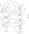
- the test specimen holder 100, 200 works in conjunction with a specimen insertion or support jig 10 ( Figs. 2 , 3 and 20-23 ) that has the purpose of allowing specimen insertion to happen on a workbench or table remotely from the test machine 1.
- the support jig holds the specimen holders 100, 200 rigidly and accurately so that bending strains on the specimen inherent to the installation process are limited and repeatable.
- the support jig 10 provides a method of introducing clamping forces into the specimen holders 100, 200 while not applying errant load to the specimen.
- the support jig 10 allows the user to verify the installation accuracy, and allows the installation of the jig/specimen holder sub-system to be installed into the test machine 1 without errant loads being applied to the test specimen until such time that the test machine 1 is in control and managing loads and displacements.
- An aspect of the disclosure is the support jig 10 ( Figs. 2 , 3 and 20-23 ) that is used to mount a test specimen 15 to test specimen holders or grips 100, 200 so as to be accurately positioned in the holders 100, 200 without undesired loading, which can damage or break the test specimen 15 as well as aligning the test specimen 15 with axes of the test specimen holders 100, 200 so as to perform required testing in the testing machine 1.
- the support jig 10 allows loading the test specimen 15 to the test specimen holders 100, 200 in an accurate and repeatable manner.
- test machine 1 such the test machine 1 described above, can be used to impart forces and/or displacements to the test specimen 15.
- test machines are known in the art as a tension or tensile tester (used for applying monotonic or single directions loads) or a tension/compression tester (which can be used in fatigue testing where alternating tension and compression loads can be applied).
- a rotational actuator not shown, can be part of the test machine 1 with or without the linear actuator 3.
- the support jig 10 allows the test specimen holders 100, 200 and the test specimen 15 attached between the holders 100, 200 to be loaded into the test machine 1 without causing breakage of the test specimen 15 because all loads between the test specimen holders 100, 200 are transferred through the support jig 10 rather than through the test specimen 15.
- the jig 10 can be detached from the test specimen holders 100, 200 so that testing can commence.
- the support jig 10 includes a frame 12 having a base 13.
- a pair of spaced-apart supports 14A, 14B is joined to the base 13.
- Each support 14A, 14B is configured to releasably hold a test specimen holder on an alignment axis 16 ( Fig. 20 ).
- a test specimen support 20 is joined to the frame 12 between the pair of spaced-apart supports 14A, 14B.
- the test specimen support 20 has an end 22 configured to hold the test specimen 15 on the alignment axis 16.
- the test specimen support 20 includes a first portion 20 joined to the base 13 or frame 12 and a second portion 20B having the end 22.
- the second portion 20B is adjustably secured to the first portion 20A so as to adjust a position of the end 22 orthogonally with respect to the alignment axis 16.
- the second portion 20B is linearly adjustable with respect to the first portion 20A.
- the second portion 20B telescopes with respect to the first portion 20A.
- the end 22 can include a recess of size and shape to hold the test specimen 15 on the alignment axis 16.
- a holding device such as a clip, clamp, tape, straps or the like can be provided on the end 22 if desired to aid in holding the test specimen 15 to the end 22.
- Fasteners 24 secure the test specimen support 20 to the frame 12, while a fastener 26 such as a setscrew can be used to fix the second portion 20B at a desired position with respect to the first portion 20A.
- the frame 12 includes an optional alignment guide 30.
- Each of the supports 14A, 14B is supported by the rail 28, but the guide 30 defines the orientation of the alignment axis 16 wherein the alignment axis 16 in effect, remains parallel to the guide 30.
- each of the supports 14A, 14B and the test specimen support 20 include a bore 34A, 34B, 34C, respectively, so as to receive the guide 30.
- the guide 30 is held in a stationary position with respect to the base 13 by a standoff 36, which in the embodiment illustrated, also includes a bore 38 to receive an end of a guide 30 while fasteners such as set screws 40 fix the guide 30 to the standoff 36.
- each fastener comprises a set screw for securing the position of each support 14A, 14B on the guide 30.
- set screw 33 secures support 14A to guide 30, while support 14B includes a similar set screw, which is on a backside of support 14B in Fig. 2 .
- a fastener such as set screw 35 is used to secure the test specimen support 20 to the guide 30.
- the guide 30 is not a requirement.
- the guide 30 is not necessary if the supports 14A, 14B and test specimen support 20 can be secured to rail 28 such that alignment of the supports 14A, 14B and test specimen support 20 are suitably aligned with each other along the alignment axis 16.
- test specimen holders 100, 200 are two different test specimen holders 100, 200.
- the test specimen holder 100 is generally used in tensile testing, but can be used also in fatigue testing at lighter loads.
- the test specimen holder 200 is particularly well suited for fatigue testing.
- Each test specimen holder 100, 200 can be used with the support jig 10.
- Each test specimen holder 100, 200 is releasably secured to each corresponding support 14A, 14B.
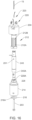
- each of the test specimen holders 100, 200 described below comprises a base or mount 102, 202 and a head body 104, 204 secured to the mount 102, 202 ( Figs. 4 and 14 ).
- the mount 102, 202 typically comprises a cylindrical member that can be inserted into corresponding recess provided in the test machine 1, such as a grip, and secured therein.
- the head body 104, 204 includes wedges that are used to hold an end of the test specimen 15 during testing.
- the supports 14A, 14B are releasably secured to the mounts 102, 202 of each of the test specimen holders 100, 200; however, it should be noted, if desired, the supports 14A, 14B can be configured to releasably secure to each of the head body 104, 204 of the test specimen holders 100, 200.
- Each support 14A, 14B includes a mounting aperture configured to receive a portion of the test specimen holder 100, 200.
- the mounting aperture is formed from a portion 40A, 40B, respectively, removably secured to an end 38A, 38B of each support 14A, 14B.
- Surfaces of the removable portions 40A, 40B and the ends 38A, 38B together engage surfaces of the test specimen holders 100, 200.
- Fasteners 42 secure each removable portion 40A, 40B to its corresponding end 38A, 38B.
- test specimens having generally flat ends to which the test specimen holders 100, 200 are attached require that the test specimen holders 100, 200 be properly oriented about the alignment axis 16 so as to coincide with and properly engage the ends of the test specimen 15.
- each of the test specimen holders 100, 200 should be oriented in the same position with respect to each other so as to orient each of the test specimen holders 100, 200 in their proper position.
- the supports 14A, 14B and holders 100, 200 include a protrusion-aperture connection between the supports 14A, 14B and the test specimen holders 100, 200 so as to align and also hold the test specimen holders 100, 200 in their proper rotational positions about the alignment axis 16.
- the protrusion comprises a pin 50 ( Fig. 3 ).
- the pin 50 can be securely fixed in the support 14A, 14B such as in the removable portion 40A, 40B and/or, as illustrated, in the end 38A, 38B of each support 14A, 14B.
- the test specimen holders 100, 200 include corresponding apertures 101, 201 of size to receive a pin 50.
- the protrusion such as a pin, can be disposed on the test specimen holder 100, 200 wherein then the aperture would be provided on the supports 14A, 14B.
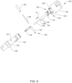
- Figs. 4 - 12 illustrate the test specimen holder 100.
- the test specimen holder 100 includes the mount or base 102 and the head body 104 secured to an end of the mount 102. At an end opposite the head body 104, the mount 102 is inserted into a corresponding recess provided in the test machine 1, which could comprise another, larger test specimen holder..
- a stop-collar 106 limits how far the mount 102 is inserted into the test machine 1.
- test specimen holder 100 be positioned in the support jig 10 where its rotational position is fixed in an accurate and repeatable manner.
- the protrusion-aperture described above can be used.
- the protrusion herein comprising the pin 50 is secured to each of the supports 14A, 14B, while the aperture 101 resides in the mount 102.
- the test specimen holder 100 includes movable wedges 120 that are supported by and slide on a support plate 118.
- Each of the wedges 120 has a specimen engaging face that faces the other wedge and engages the test specimen 15.
- the wedges 120 are planar for use with flat test specimens; however this should not be considered limiting in that the wedges 120 can be configured to hold test specimens having other shapes such as test specimens having cylindrical ends, where for example, the wedges 120 would include notches.
- the wedges 120 engage the test specimen 15 from opposite sides.
- Each wedge 120 includes an inclined back surface 122. Inclined surfaces 124 of a head body 104 engage the inclined back surfaces 122 of each wedge 120 and drive or urge the wedges 120 toward each other with relative displacement between the head body 104 and the wedges 120.
- Springs 130 are attached to the wedges 120 and have a spring bias that drives or urges the wedges 120 away from each other so as to create a space and allow easy insertion of the ends of the test specimen 15 between wedges 120.
- Each of the springs 130 comprise a torsion spring having one end insertable into a recess or aperture 132 ( Fig. 12 ) provided in the wedge 120 while the other end is fixedly retained by the head body 104, herein with an opposite end received in a recess or aperture 134 ( Fig. 8 ).
- the support plate 118 for the wedges 120 is mounted to a support rod or shaft 140 that extends downwardly away from the head body 104.
- the support plate 118 includes upstanding sides or edges that maintain the orientation of the wedges 120 so as to generally face each other but allow movement of the wedges 120 on the support plate 118 towards and away from each other.
- the test specimen holder 100 includes a bias spring 142 that generally biases the support shaft 140 upwardly towards the head body 104 so as to urge the wedges 120 towards each other and to engage the end of the test specimen located therebetween.
- the bias spring 142 herein is a coil spring received in a bore 144 provided in the mount 102.
- the support shaft 140 includes an extending portion 146 having a width allowing it to be inserted into the coils provided in the bias spring 142.
- a flange 148 is provided in the support shaft 140 that engages the uppermost coil of the bias spring 142.
- the driven part 228 can also be formed as a disc having an aperture 228A through which the portion 240A of the support shaft 240 extends therethrough.
- the aperture 228A comprises a slot with a longitudinal axis being transverse to the longitudinal axis of the support shaft 240.
- the slotted aperture 228A allows the driven element 228 to move transversely with respect to the longitudinal axis of a support shaft 240.
- the actuator 230 comprises two separate actuators 230A, 230B wherein a first actuator 230A drives the driven part in the direct indicated by arrow 250A while a second actuator 230B is used to drive the drive element 228 in the opposite direction by arrow 250B.
- One or both of the actuators 230A, 230B can comprise a threaded element threadably engaging the first portion 214.
- the specimen holders 100, 200 can be mounted in the test machine 1, and once secured, the support jig 10 can then be removed.
- one mount of the test specimen holders 100 is installed in the test machine 1 for example with a direct connection via a clevis pin to the load cell 9.
- the test machine 1 can be operated so as to position the other end, for example, having grip 282 so as to grasp the end of the other test specimen holder 100.
- the test machine 1 is placed in force control and operated so that zero force is being applied between the test specimen holders 100. With zero force applied, the jig 10 can then be removed and the test machine 1 is now ready to conduct a test upon the test specimen. Reverification of specimen alignment in the test specimen holders can again be verified through various means-mechanical measurement, optical measurement via light/shadow, lasers, and cameras. Other means of verification like photo elastic paint could also be used.
Landscapes
- Physics & Mathematics (AREA)
- Health & Medical Sciences (AREA)
- Life Sciences & Earth Sciences (AREA)
- Chemical & Material Sciences (AREA)
- Analytical Chemistry (AREA)
- Biochemistry (AREA)
- General Health & Medical Sciences (AREA)
- General Physics & Mathematics (AREA)
- Immunology (AREA)
- Pathology (AREA)
- Investigating Strength Of Materials By Application Of Mechanical Stress (AREA)
Claims (13)
- Gabarit de support (10) destiné à être utilisé avec une machine d'essai (1) appliquant des charges de traction, le gabarit de support (10) comprenant :un cadre (12) ; etune paire de supports (14A, 14B) espacés joints au cadre (12) pour fournir un axe d'alignement (16), chaque support (14A, 14B) étant configuré pour maintenir de manière libérable un dispositif de maintien d'éprouvette (100, 200) sur l'axe d'alignement (16) dans une relation spatiale fixe, des extrémités des dispositifs de maintien d'éprouvette (100, 200) pouvant être montées sur la machine d'essai (1) face à des directions opposées ; etun support d'éprouvette (20) joint au cadre (12) entre la paire de supports (14A, 14B) espacés, le support d'éprouvette (20) ayant une extrémité (22) configurée pour maintenir une éprouvette (15) sur l'axe d'alignement.
- Gabarit de support selon la revendication 1, dans lequel le support d'éprouvette (20) comprend une première partie (20A) jointe au cadre (12) et une deuxième partie (20B) ayant l'extrémité (22), la deuxième partie (20B) étant fixée de manière réglable à la première partie (20A) de manière à régler une position de l'extrémité (22) orthogonalement vis-à-vis de l'axe d'alignement (16), dans lequel la deuxième partie (20B) est de préférence réglable linéairement vis-à-vis de à la première partie (20A) de telle sorte que dans lequel la deuxième partie (20B) est télescopique vis-à-vis de la première partie (20B).
- Gabarit de support (10) selon la revendication 1 ou la revendication 2, dans lequel l'extrémité (22) comprend un évidement configuré pour recevoir une éprouvette (15).
- Gabarit de support (10) selon l'une quelconque des revendications 1 à 3 dans lequel la paire de supports (14A, 14B) comprend un premier support (14A) et un deuxième support (14B), et dans lequel le premier support (14A) peut être positionné de manière réglable sur le cadre (12) pour régler axialement une position du premier support (14A) sur l'axe d'alignement (16), dans lequel le deuxième support (14B) peut être positionné de manière réglable sur le cadre (12) pour régler axialement une position du deuxième support (14B) sur l'axe d'alignement (16).
- Gabarit de support (10) selon l'une quelconque des revendications 1 à 4 dans lequel chaque support (14A, 14B) comporte un évidement ou une saillie espacé de l'axe d'alignement (16) qui est complémentaire d'une saillie ou d'un évidement, respectivement, prévu sur le dispositif de maintien d'éprouvette (100, 200) associé pouvant être fixé au support (14A, 14B).
- Gabarit de support (10) selon l'une quelconque des revendications 1 à 5 dans lequel chaque support (14A, 14B) fournit une ouverture de montage destinée à recevoir une partie du dispositif de maintien d'éprouvette (100, 200).
- Gabarit de support (10) selon l'une quelconque des revendications 1 à 6 dans lequel une extrémité (38A, 38B) de chaque support (14A, 14B) comprend une partie amovible (40A, 40B) pouvant être fixée à l'extrémité (38A, 38B), par exemple dans lequel l'extrémité (38A, 38B) de chaque support (14A, 14B) et la partie amovible (40A, 40B) comportent des surfaces pouvant venir en prise avec le dispositif de maintien d'éprouvette (100, 200) qui sont complémentaires du dispositif de maintien d'éprouvette (100, 200).
- Gabarit de support (10) selon l'une quelconque des revendications 1 à 7 et comprenant en outre un premier dispositif de maintien d'éprouvette (100, 200) pouvant être fixé de manière amovible à l'un des supports (14A, 14B) et un deuxième dispositif de maintien d'éprouvette (100, 200) pouvant être fixé de manière amovible à l'autre des supports (14A, 14B), par exemple dans lequel le premier dispositif de maintien d'éprouvette (100, 200) et le deuxième dispositif de maintien d'éprouvette (100, 200) comportent chacun une tête (104, 204) configurée pour maintenir une extrémité de l'éprouvette (15) et une base (102, 202) attachée à la tête (104, 204), la base (102, 202) ayant chaque extrémité configurée pour un montage sur la machine d'essai de traction (1) dans lequel chaque extrémité (38A, 38B) de chaque support (40A, 40B) est configurée pour mettre en prise libérable une surface externe de la base (102, 202) de chaque dispositif de maintien d'éprouvette (100, 200) correspondant dans lequel chacun des dispositifs de maintien d'éprouvette (100, 200) comporte éventuellement un mécanisme pour appliquer une force de serrage de précharge à l'extrémité de l'éprouvette (15).
- Procédé de chargement d'une éprouvette (15) dans une machine d'essai de traction (1) ayant un premier dispositif de maintien d'éprouvette (100, 200) et un deuxième dispositif de maintien d'éprouvette (100, 200), le procédé comprenant :la fourniture d'un gabarit de support (10) à distance de la machine d'essai (1) ;le montage du premier dispositif de maintien d'éprouvette (100, 200) et du deuxième dispositif de maintien d'éprouvette (100, 200) sur le gabarit de support (10) de sorte que des têtes (104, 204) configurées pour maintenir des extrémités de l'éprouvette (15) sont l'une en face de l'autre et que des extrémités des dispositifs de maintien d'éprouvette (100, 200) pouvant être fixées à la machine d'essai (1) sont face à des directions opposées, les dispositifs de maintien d'éprouvette (100, 200) étant alignés l'un avec l'autre et étant situés sur un axe d'alignement (16) commun ;la fixation de têtes (104, 204) des premier et deuxième dispositifs de maintien d'éprouvette (100, 200) à des première et deuxième extrémités, respectivement, de l'éprouvette (15) ; etle montage du premier dispositif de maintien d'éprouvette (100, 200) et du deuxième dispositif de maintien d'éprouvette (100, 200) dans la machine d'essai de traction (1) dans lequel le gabarit de support (10) maintient le premier dispositif de maintien d'éprouvette (100, 200) et le deuxième dispositif de maintien d'éprouvette (100, 200) sur l'axe d'alignement (16) et dans une relation spatiale fixe l'un par rapport à l'autre ; et le montage de l'éprouvette (15) sur un support d'éprouvette (20) joint au gabarit de support (10) pour qu'elle soit alignée avec l'axe d'alignement (16).
- Procédé selon la revendication 9 dans lequel le montage de l'éprouvette (15) sur le support d'éprouvette (20) pour qu'elle soit alignée avec l'axe d'alignement (16) s'effectue de préférence avant la fixation des têtes (104, 204) du premier dispositif de maintien d'éprouvette (100, 200) et du deuxième dispositif de maintien d'éprouvette (100, 200) sur l'éprouvette (15).
- Procédé selon l'une quelconque des revendications 9 et 10 dans lequel le gabarit (10) comporte un premier support (14A) et un deuxième support (14B) couplés à un cadre (12), et dans lequel le montage du premier dispositif de maintien d'éprouvette (100, 200) et du deuxième dispositif de maintien d'éprouvette (100, 200) sur un gabarit de support (10) comprend le montage du premier dispositif de maintien d'éprouvette (100, 200) sur le premier support (14A) et du deuxième dispositif de maintien d'éprouvette (100, 200) sur le deuxième support (14B).
- Procédé selon l'une quelconque des revendications 9 à 11 dans lequel le montage du premier dispositif de maintien d'éprouvette (100, 200) et du deuxième dispositif de maintien d'éprouvette (100, 200) dans la machine d'essai de traction (1) s'effectue après le montage du premier dispositif de maintien d'éprouvette (100, 200) et du deuxième dispositif de maintien d'éprouvette (100, 200) sur le gabarit de support (10) et/ou la fixation des têtes (104, 204) des premier et deuxième dispositifs de maintien d'éprouvette (100, 200) sur l'éprouvette (15).
- Procédé selon l'une quelconque des revendications 9 à 12 dans lequel le montage du premier dispositif de maintien d'éprouvette (100, 200) et du deuxième dispositif de maintien d'éprouvette (100, 200) sur le gabarit de support (10) comporte la fixation d'une position en rotation de chacun du premiers dispositif de maintien d'éprouvette (100, 200) et du deuxième dispositif de maintien d'éprouvette (100, 200) autour de l'axe d'alignement (16) ; et/ou dans lequel la fixation de têtes (104, 204) des premier et deuxième dispositifs de maintien d'éprouvette (100, 200) à des première et deuxième extrémités, respectivement, de l'éprouvette (15) comporte l'application d'une force de maintien de serrage de précharge à une extrémité de l'éprouvette (15).
Applications Claiming Priority (2)
| Application Number | Priority Date | Filing Date | Title |
|---|---|---|---|
| US202063105199P | 2020-10-23 | 2020-10-23 | |
| PCT/US2021/056319 WO2022087463A1 (fr) | 2020-10-23 | 2021-10-22 | Gabarit de support et spécimen d'épreuve utilisé avec le gabarit de support |
Publications (2)
| Publication Number | Publication Date |
|---|---|
| EP4232796A1 EP4232796A1 (fr) | 2023-08-30 |
| EP4232796B1 true EP4232796B1 (fr) | 2025-07-02 |
Family
ID=78821485
Family Applications (1)
| Application Number | Title | Priority Date | Filing Date |
|---|---|---|---|
| EP21819627.7A Active EP4232796B1 (fr) | 2020-10-23 | 2021-10-22 | Gabarit de support |
Country Status (7)
| Country | Link |
|---|---|
| US (1) | US11808738B2 (fr) |
| EP (1) | EP4232796B1 (fr) |
| JP (1) | JP7835745B2 (fr) |
| KR (1) | KR20230091989A (fr) |
| CN (1) | CN116324370A (fr) |
| CA (1) | CA3197692A1 (fr) |
| WO (1) | WO2022087463A1 (fr) |
Families Citing this family (4)
| Publication number | Priority date | Publication date | Assignee | Title |
|---|---|---|---|---|
| US20240011752A1 (en) * | 2022-07-07 | 2024-01-11 | Illinois Tool Works Inc. | Systems and methods to measure specimen dimensions |
| KR102936668B1 (ko) | 2022-09-19 | 2026-03-10 | (주)인스케이프 | 포고핀 외관 검사를 위한 그리퍼 |
| TWI826100B (zh) * | 2022-11-04 | 2023-12-11 | 國立臺灣海洋大學 | 磨耗試驗機構 |
| US20250164364A1 (en) * | 2023-11-17 | 2025-05-22 | Illinois Tool Works Inc. | Alignment apparatus and methods for testing system |
Family Cites Families (13)
| Publication number | Priority date | Publication date | Assignee | Title |
|---|---|---|---|---|
| US3309918A (en) * | 1965-03-22 | 1967-03-21 | Gen Electric | Test sample holding and alignment means for tensile testing machines |
| US4537080A (en) * | 1982-02-18 | 1985-08-27 | Mts Systems Corporation | Side loading specimen grip |
| JPS60542U (ja) * | 1983-06-16 | 1985-01-05 | 株式会社明石製作所 | 破断試験片保持具 |
| US4594900A (en) * | 1985-04-25 | 1986-06-17 | Washington State University Research Foundation, Inc. | Axial load testing machine |
| JPH10170418A (ja) * | 1996-12-05 | 1998-06-26 | Shimadzu Corp | つかみ具 |
| JPH11281546A (ja) * | 1998-03-27 | 1999-10-15 | Masaki Shiratori | 材料試験機 |
| JP5202998B2 (ja) * | 2008-03-10 | 2013-06-05 | 高周波熱錬株式会社 | チャック装置、引張試験装置、およびチャック装置の製造方法 |
| EP2261633A1 (fr) * | 2009-06-10 | 2010-12-15 | Becton Dickinson France | Dispositif support pour article transparent et procédé pour placer ledit article en compression |
| US9695644B2 (en) * | 2012-05-14 | 2017-07-04 | Drill-Quip Inc. | Smart riser handling tool |
| ITMI20131669A1 (it) * | 2013-10-09 | 2015-04-10 | Freni Brembo Spa | Dispositivo e metodo di caratterizzazione delle proprieta' elastiche di un materiale d'attrito |
| CN103760037B (zh) * | 2014-01-23 | 2016-03-02 | 湖南大学 | 一种轴承式损伤生物力学三点弯曲试验装置和试验方法 |
| JP2016205824A (ja) * | 2015-04-15 | 2016-12-08 | 株式会社島津製作所 | 材料試験機 |
| JP6947748B2 (ja) * | 2016-04-01 | 2021-10-13 | イリノイ トゥール ワークス インコーポレイティド | 側方に作用する空気圧式把持部における布帛を試験するための組込み楔部材 |
-
2021
- 2021-10-22 US US17/508,756 patent/US11808738B2/en active Active
- 2021-10-22 CN CN202180070927.0A patent/CN116324370A/zh active Pending
- 2021-10-22 CA CA3197692A patent/CA3197692A1/fr active Pending
- 2021-10-22 WO PCT/US2021/056319 patent/WO2022087463A1/fr not_active Ceased
- 2021-10-22 KR KR1020237017244A patent/KR20230091989A/ko active Pending
- 2021-10-22 JP JP2023524983A patent/JP7835745B2/ja active Active
- 2021-10-22 EP EP21819627.7A patent/EP4232796B1/fr active Active
Also Published As
| Publication number | Publication date |
|---|---|
| JP2023546957A (ja) | 2023-11-08 |
| CN116324370A (zh) | 2023-06-23 |
| JP7835745B2 (ja) | 2026-03-25 |
| US11808738B2 (en) | 2023-11-07 |
| CA3197692A1 (fr) | 2022-04-28 |
| WO2022087463A1 (fr) | 2022-04-28 |
| EP4232796A1 (fr) | 2023-08-30 |
| KR20230091989A (ko) | 2023-06-23 |
| US20220128440A1 (en) | 2022-04-28 |
Similar Documents
| Publication | Publication Date | Title |
|---|---|---|
| EP4232796B1 (fr) | Gabarit de support | |
| CN110286085B (zh) | 90°剥离强度测试夹具、剥离强度测试设备及方法 | |
| JP2023546957A5 (fr) | ||
| CN111721625B (zh) | 一种高速拉伸试样对中装置和方法 | |
| CN212512774U (zh) | 一种测量工具 | |
| JPS61228182A (ja) | チユーブ挿入装置 | |
| JP2025520812A (ja) | 薄膜試料を配置する方法及び装置 | |
| CN120333991B (zh) | 一种材料检测用拉力试验装置 | |
| KR20210142307A (ko) | 양방향 조절이 가능한 단일-종단 공압 고정장치 | |
| KR20190097897A (ko) | 인장 시험 장치 | |
| CN220985743U (zh) | 一种相机对焦测试平台 | |
| CN222327814U (zh) | 精密凸轮式夹治装置 | |
| JPH0663247U (ja) | クランプ機構およびワーク位置決め装置 | |
| US6765734B1 (en) | Adjustable sample holder for optical equipment | |
| JP2025520675A (ja) | 試験片の材料試験用のモジュール式材料試験装置 | |
| CN110208939B (zh) | 一种载玻片夹持装置及显微镜系统 | |
| KR101564026B1 (ko) | 계측타겟 고정 지그 | |
| CN115533828A (zh) | 组装装置 | |
| KR20120034885A (ko) | 유연소재의 시험장치 | |
| JP2022019919A (ja) | ケーブル加工装置のための位置合わせ方法 | |
| CN109115385A (zh) | 扭力检测固定装置 | |
| CN222143984U (zh) | 用于量具的校验装置 | |
| CN211717937U (zh) | 万能材料试验机 | |
| CN219996850U (zh) | 曲面涂层附着力的测试装置 | |
| CN112945738A (zh) | 力学试验装置 |
Legal Events
| Date | Code | Title | Description |
|---|---|---|---|
| STAA | Information on the status of an ep patent application or granted ep patent |
Free format text: STATUS: UNKNOWN |
|
| STAA | Information on the status of an ep patent application or granted ep patent |
Free format text: STATUS: THE INTERNATIONAL PUBLICATION HAS BEEN MADE |
|
| PUAI | Public reference made under article 153(3) epc to a published international application that has entered the european phase |
Free format text: ORIGINAL CODE: 0009012 |
|
| STAA | Information on the status of an ep patent application or granted ep patent |
Free format text: STATUS: REQUEST FOR EXAMINATION WAS MADE |
|
| 17P | Request for examination filed |
Effective date: 20230309 |
|
| AK | Designated contracting states |
Kind code of ref document: A1 Designated state(s): AL AT BE BG CH CY CZ DE DK EE ES FI FR GB GR HR HU IE IS IT LI LT LU LV MC MK MT NL NO PL PT RO RS SE SI SK SM TR |
|
| DAV | Request for validation of the european patent (deleted) | ||
| DAX | Request for extension of the european patent (deleted) | ||
| GRAP | Despatch of communication of intention to grant a patent |
Free format text: ORIGINAL CODE: EPIDOSNIGR1 |
|
| STAA | Information on the status of an ep patent application or granted ep patent |
Free format text: STATUS: GRANT OF PATENT IS INTENDED |
|
| INTG | Intention to grant announced |
Effective date: 20250225 |
|
| GRAS | Grant fee paid |
Free format text: ORIGINAL CODE: EPIDOSNIGR3 |
|
| GRAA | (expected) grant |
Free format text: ORIGINAL CODE: 0009210 |
|
| STAA | Information on the status of an ep patent application or granted ep patent |
Free format text: STATUS: THE PATENT HAS BEEN GRANTED |
|
| P01 | Opt-out of the competence of the unified patent court (upc) registered |
Free format text: CASE NUMBER: APP_20771/2025 Effective date: 20250430 |
|
| AK | Designated contracting states |
Kind code of ref document: B1 Designated state(s): AL AT BE BG CH CY CZ DE DK EE ES FI FR GB GR HR HU IE IS IT LI LT LU LV MC MK MT NL NO PL PT RO RS SE SI SK SM TR |
|
| REG | Reference to a national code |
Ref country code: GB Ref legal event code: FG4D |
|
| REG | Reference to a national code |
Ref country code: CH Ref legal event code: EP |
|
| REG | Reference to a national code |
Ref country code: DE Ref legal event code: R096 Ref document number: 602021033510 Country of ref document: DE |
|
| REG | Reference to a national code |
Ref country code: IE Ref legal event code: FG4D |
|
| REG | Reference to a national code |
Ref country code: NL Ref legal event code: MP Effective date: 20250702 |
|
| PG25 | Lapsed in a contracting state [announced via postgrant information from national office to epo] |
Ref country code: PT Free format text: LAPSE BECAUSE OF FAILURE TO SUBMIT A TRANSLATION OF THE DESCRIPTION OR TO PAY THE FEE WITHIN THE PRESCRIBED TIME-LIMIT Effective date: 20251103 |
|
| PG25 | Lapsed in a contracting state [announced via postgrant information from national office to epo] |
Ref country code: NL Free format text: LAPSE BECAUSE OF FAILURE TO SUBMIT A TRANSLATION OF THE DESCRIPTION OR TO PAY THE FEE WITHIN THE PRESCRIBED TIME-LIMIT Effective date: 20250702 |
|
| REG | Reference to a national code |
Ref country code: AT Ref legal event code: MK05 Ref document number: 1809711 Country of ref document: AT Kind code of ref document: T Effective date: 20250702 |
|
| PG25 | Lapsed in a contracting state [announced via postgrant information from national office to epo] |
Ref country code: IS Free format text: LAPSE BECAUSE OF FAILURE TO SUBMIT A TRANSLATION OF THE DESCRIPTION OR TO PAY THE FEE WITHIN THE PRESCRIBED TIME-LIMIT Effective date: 20251102 |
|
| PGFP | Annual fee paid to national office [announced via postgrant information from national office to epo] |
Ref country code: DE Payment date: 20251029 Year of fee payment: 5 |
|
| PGFP | Annual fee paid to national office [announced via postgrant information from national office to epo] |
Ref country code: GB Payment date: 20251027 Year of fee payment: 5 |
|
| PG25 | Lapsed in a contracting state [announced via postgrant information from national office to epo] |
Ref country code: NO Free format text: LAPSE BECAUSE OF FAILURE TO SUBMIT A TRANSLATION OF THE DESCRIPTION OR TO PAY THE FEE WITHIN THE PRESCRIBED TIME-LIMIT Effective date: 20251002 |
|
| REG | Reference to a national code |
Ref country code: LT Ref legal event code: MG9D |
|
| PG25 | Lapsed in a contracting state [announced via postgrant information from national office to epo] |
Ref country code: AT Free format text: LAPSE BECAUSE OF FAILURE TO SUBMIT A TRANSLATION OF THE DESCRIPTION OR TO PAY THE FEE WITHIN THE PRESCRIBED TIME-LIMIT Effective date: 20250702 |
|
| PG25 | Lapsed in a contracting state [announced via postgrant information from national office to epo] |
Ref country code: FI Free format text: LAPSE BECAUSE OF FAILURE TO SUBMIT A TRANSLATION OF THE DESCRIPTION OR TO PAY THE FEE WITHIN THE PRESCRIBED TIME-LIMIT Effective date: 20250702 |
|
| PG25 | Lapsed in a contracting state [announced via postgrant information from national office to epo] |
Ref country code: HR Free format text: LAPSE BECAUSE OF FAILURE TO SUBMIT A TRANSLATION OF THE DESCRIPTION OR TO PAY THE FEE WITHIN THE PRESCRIBED TIME-LIMIT Effective date: 20250702 |
|
| PGFP | Annual fee paid to national office [announced via postgrant information from national office to epo] |
Ref country code: FR Payment date: 20251027 Year of fee payment: 5 |
|
| PG25 | Lapsed in a contracting state [announced via postgrant information from national office to epo] |
Ref country code: GR Free format text: LAPSE BECAUSE OF FAILURE TO SUBMIT A TRANSLATION OF THE DESCRIPTION OR TO PAY THE FEE WITHIN THE PRESCRIBED TIME-LIMIT Effective date: 20251003 |
|
| PG25 | Lapsed in a contracting state [announced via postgrant information from national office to epo] |
Ref country code: CZ Free format text: LAPSE BECAUSE OF FAILURE TO SUBMIT A TRANSLATION OF THE DESCRIPTION OR TO PAY THE FEE WITHIN THE PRESCRIBED TIME-LIMIT Effective date: 20250702 Ref country code: SE Free format text: LAPSE BECAUSE OF FAILURE TO SUBMIT A TRANSLATION OF THE DESCRIPTION OR TO PAY THE FEE WITHIN THE PRESCRIBED TIME-LIMIT Effective date: 20250702 |
|
| PG25 | Lapsed in a contracting state [announced via postgrant information from national office to epo] |
Ref country code: LV Free format text: LAPSE BECAUSE OF FAILURE TO SUBMIT A TRANSLATION OF THE DESCRIPTION OR TO PAY THE FEE WITHIN THE PRESCRIBED TIME-LIMIT Effective date: 20250702 |
|
| PG25 | Lapsed in a contracting state [announced via postgrant information from national office to epo] |
Ref country code: PL Free format text: LAPSE BECAUSE OF FAILURE TO SUBMIT A TRANSLATION OF THE DESCRIPTION OR TO PAY THE FEE WITHIN THE PRESCRIBED TIME-LIMIT Effective date: 20250702 Ref country code: BG Free format text: LAPSE BECAUSE OF FAILURE TO SUBMIT A TRANSLATION OF THE DESCRIPTION OR TO PAY THE FEE WITHIN THE PRESCRIBED TIME-LIMIT Effective date: 20250702 |
|
| PG25 | Lapsed in a contracting state [announced via postgrant information from national office to epo] |
Ref country code: RS Free format text: LAPSE BECAUSE OF FAILURE TO SUBMIT A TRANSLATION OF THE DESCRIPTION OR TO PAY THE FEE WITHIN THE PRESCRIBED TIME-LIMIT Effective date: 20251002 |
|
| PG25 | Lapsed in a contracting state [announced via postgrant information from national office to epo] |
Ref country code: ES Free format text: LAPSE BECAUSE OF FAILURE TO SUBMIT A TRANSLATION OF THE DESCRIPTION OR TO PAY THE FEE WITHIN THE PRESCRIBED TIME-LIMIT Effective date: 20250702 |
|
| PG25 | Lapsed in a contracting state [announced via postgrant information from national office to epo] |
Ref country code: RO Free format text: LAPSE BECAUSE OF FAILURE TO SUBMIT A TRANSLATION OF THE DESCRIPTION OR TO PAY THE FEE WITHIN THE PRESCRIBED TIME-LIMIT Effective date: 20250702 |
|
| PG25 | Lapsed in a contracting state [announced via postgrant information from national office to epo] |
Ref country code: SM Free format text: LAPSE BECAUSE OF FAILURE TO SUBMIT A TRANSLATION OF THE DESCRIPTION OR TO PAY THE FEE WITHIN THE PRESCRIBED TIME-LIMIT Effective date: 20250702 |
|
| PG25 | Lapsed in a contracting state [announced via postgrant information from national office to epo] |
Ref country code: DK Free format text: LAPSE BECAUSE OF FAILURE TO SUBMIT A TRANSLATION OF THE DESCRIPTION OR TO PAY THE FEE WITHIN THE PRESCRIBED TIME-LIMIT Effective date: 20250702 |
|
| PG25 | Lapsed in a contracting state [announced via postgrant information from national office to epo] |
Ref country code: IT Free format text: LAPSE BECAUSE OF FAILURE TO SUBMIT A TRANSLATION OF THE DESCRIPTION OR TO PAY THE FEE WITHIN THE PRESCRIBED TIME-LIMIT Effective date: 20250702 |
|
| PG25 | Lapsed in a contracting state [announced via postgrant information from national office to epo] |
Ref country code: SK Free format text: LAPSE BECAUSE OF FAILURE TO SUBMIT A TRANSLATION OF THE DESCRIPTION OR TO PAY THE FEE WITHIN THE PRESCRIBED TIME-LIMIT Effective date: 20250702 Ref country code: EE Free format text: LAPSE BECAUSE OF FAILURE TO SUBMIT A TRANSLATION OF THE DESCRIPTION OR TO PAY THE FEE WITHIN THE PRESCRIBED TIME-LIMIT Effective date: 20250702 |