EP4234776A1 - Système de filage et méthode de contrôle d'un système de filage - Google Patents
Système de filage et méthode de contrôle d'un système de filage Download PDFInfo
- Publication number
- EP4234776A1 EP4234776A1 EP23150248.5A EP23150248A EP4234776A1 EP 4234776 A1 EP4234776 A1 EP 4234776A1 EP 23150248 A EP23150248 A EP 23150248A EP 4234776 A1 EP4234776 A1 EP 4234776A1
- Authority
- EP
- European Patent Office
- Prior art keywords
- spinning
- spinneret
- air
- cooling unit
- molten polymer
- Prior art date
- Legal status (The legal status is an assumption and is not a legal conclusion. Google has not performed a legal analysis and makes no representation as to the accuracy of the status listed.)
- Pending
Links
- 238000009987 spinning Methods 0.000 title claims abstract description 481
- 238000000034 method Methods 0.000 title claims description 16
- 238000001816 cooling Methods 0.000 claims abstract description 274
- 229920000642 polymer Polymers 0.000 claims abstract description 128
- 230000007423 decrease Effects 0.000 claims abstract description 59
- 238000012423 maintenance Methods 0.000 claims description 168
- 230000001629 suppression Effects 0.000 claims description 17
- 238000007664 blowing Methods 0.000 claims description 13
- 238000002360 preparation method Methods 0.000 claims description 13
- 230000007246 mechanism Effects 0.000 claims description 6
- 230000004044 response Effects 0.000 description 19
- 230000004048 modification Effects 0.000 description 13
- 238000012986 modification Methods 0.000 description 13
- 230000000704 physical effect Effects 0.000 description 11
- 238000004519 manufacturing process Methods 0.000 description 10
- 238000004140 cleaning Methods 0.000 description 9
- 238000001514 detection method Methods 0.000 description 7
- 230000008646 thermal stress Effects 0.000 description 7
- 238000011156 evaluation Methods 0.000 description 6
- 238000010186 staining Methods 0.000 description 6
- 238000010586 diagram Methods 0.000 description 5
- 230000008859 change Effects 0.000 description 4
- 239000003795 chemical substances by application Substances 0.000 description 4
- 230000000694 effects Effects 0.000 description 3
- 239000000463 material Substances 0.000 description 3
- 230000009467 reduction Effects 0.000 description 3
- 238000007789 sealing Methods 0.000 description 3
- 238000000638 solvent extraction Methods 0.000 description 3
- 230000033228 biological regulation Effects 0.000 description 2
- 230000003247 decreasing effect Effects 0.000 description 2
- 238000007711 solidification Methods 0.000 description 2
- 230000008023 solidification Effects 0.000 description 2
- 238000011144 upstream manufacturing Methods 0.000 description 2
- 230000004888 barrier function Effects 0.000 description 1
- 230000005540 biological transmission Effects 0.000 description 1
- 125000004122 cyclic group Chemical group 0.000 description 1
- 230000003028 elevating effect Effects 0.000 description 1
- 230000002349 favourable effect Effects 0.000 description 1
- 230000002452 interceptive effect Effects 0.000 description 1
- 239000007788 liquid Substances 0.000 description 1
- 238000002074 melt spinning Methods 0.000 description 1
- 238000012545 processing Methods 0.000 description 1
- 238000004080 punching Methods 0.000 description 1
- 239000007787 solid Substances 0.000 description 1
- 230000000087 stabilizing effect Effects 0.000 description 1
- 239000012209 synthetic fiber Substances 0.000 description 1
- 229920002994 synthetic fiber Polymers 0.000 description 1
- 238000012795 verification Methods 0.000 description 1
Images








Classifications
-
- D—TEXTILES; PAPER
- D01—NATURAL OR MAN-MADE THREADS OR FIBRES; SPINNING
- D01D—MECHANICAL METHODS OR APPARATUS IN THE MANUFACTURE OF ARTIFICIAL FILAMENTS, THREADS, FIBRES, BRISTLES OR RIBBONS
- D01D5/00—Formation of filaments, threads, or the like
- D01D5/08—Melt spinning methods
- D01D5/088—Cooling filaments, threads or the like, leaving the spinnerettes
- D01D5/092—Cooling filaments, threads or the like, leaving the spinnerettes in shafts or chimneys
-
- D—TEXTILES; PAPER
- D01—NATURAL OR MAN-MADE THREADS OR FIBRES; SPINNING
- D01D—MECHANICAL METHODS OR APPARATUS IN THE MANUFACTURE OF ARTIFICIAL FILAMENTS, THREADS, FIBRES, BRISTLES OR RIBBONS
- D01D13/00—Complete machines for producing artificial threads
- D01D13/02—Elements of machines in combination
-
- D—TEXTILES; PAPER
- D01—NATURAL OR MAN-MADE THREADS OR FIBRES; SPINNING
- D01D—MECHANICAL METHODS OR APPARATUS IN THE MANUFACTURE OF ARTIFICIAL FILAMENTS, THREADS, FIBRES, BRISTLES OR RIBBONS
- D01D4/00—Spinnerette packs; Cleaning thereof
- D01D4/04—Cleaning spinnerettes or other parts of the spinnerette packs
Definitions
- the present invention relates to a spinning system and a controlling method thereof.
- a spinning system has been provided with a cooling unit arranged below a spinning beam having a spinning pack inserted therein including a spinneret for allowing high-temperature molten polymer to be spun therefrom.
- the cooling unit includes a spinning cylinder surrounding the high-temperature molten polymer spun from the spinneret.
- the cooling unit is configured to supply cooling air to the spinning cylinder to blow the cooling air on the high-temperature molten polymer so that the molten polymer can be cooled to be solidified, and thereby yarn is formed.
- Patent Document 1 discloses maintenance on a spinning system conducted while a cooling unit is lowered to ensure a working space between the cooling unit and a spinning beam (see paragraph 0026 in particular).
- Patent Document 2 e.g., discloses a filament cooling unit elevated and lowered for exchanging a spinning pack or performing surface cleaning (see paragraph 0023 in particular).
- the present invention has been made in view of the above-described technical problems. It is the objective of the present invention to provide a spinning system configured such that decrease in temperature at a spinneret and in ambient temperature around the spinneret can be suppressed.
- a first aspect of the present invention is a spinning system comprising:
- the cooling unit having been caused to move downward it is possible to stop the air flowing or suppress an amount of the air flowing to the spinning cylinder.
- decrease in temperature at the spinneret and in ambient temperature around the spinneret both to be caused by the air flowing upward from the spinning cylinder can be suppressed.
- the spinning system it is possible to facilitate the yarn threading work after the completion of maintenance while suppressing decrease in temperature at the spinneret and in ambient temperature around the spinneret. More specifically, there are probabilities that stopping supplying the cooling air or suppressing an amount of the supplied cooling air to the spinning cylinder during maintenance on the spinning apparatus would cause the failure to cool and solidify molten polymer spun from the spinneret. Such a failure would impose difficulty in implementing a work itself of threading yarns through the spinning cylinder after the completion of maintenance.
- a fourth aspect of the spinning system in the above-described third aspect is characterized in that the blower stops operation when the spinning beam and the cooling unit abut each other.
- the abutting between the spinning beam and the cooling unit closes an upper opening of the spinning cylinder.
- the closed upper opening of the spinning cylinder causes the cooling air supplied from the cooling unit to mostly flow downward, and therefore decrease in temperature at the spinneret and in ambient temperature around the spinneret can be suppressed.
- a time taken for a temperature at the spinneret and an ambient temperature around the spinneret to return to their respective original levels can be shortened, and eventually, a time taken for yarn to be stabilized in physical properties can be shortened.
- a fifth aspect of the present invention is a method of controlling a spinning system comprising:
- a six aspect of the controlling method in the above-described fifth aspect is characterized in that the temperature decrease suppression step includes: a step of stopping supply of cooling air to the spinning cylinder; or a step of suppressing supply, to the spinning cylinder, of cooling air in amount in comparison with a state before the preparation step is performed.
- air can be blown to the molten polymer passing through a gap formed between the spinning beam and the cooling unit in a direction intersecting a yarn path of the molten polymer.
- This makes it possible to cool and solidify the molten polymer spun from the spinneret while suppressing decrease in temperature at the spinneret and in ambient temperature around the spinneret.
- yarn threading work of threading yarns through the spinning cylinder can be facilitated.
- the supply of cooling air to the spinning cylinder may be stopped or an amount of the supplied cooling air may be suppressed at least in a state of having caused the cooling unit to move downward with respect to the spinning beam.
- a seventh aspect of the controlling method in the above-described sixth aspect is characterized in that the temperature decrease suppression step further includes: an air blowing step of blowing air toward between the spinning beam and the cooling unit in a direction intersecting a yarn path of the molten polymer spun from the spinneret.
- the above-described seventh aspect of the controlling method it is possible to facilitate the yarn threading work after the completion of maintenance while suppressing decrease in temperature at the spinneret and in ambient temperature around the spinneret. More specifically, there are probabilities that stopping supplying the cooling air or suppressing an amount of the supplied cooling air to the spinning cylinder during maintenance on the spinning apparatus would cause the failure to cool and solidify molten polymer spun from the spinneret. Such a failure would impose difficulty in implementing a work itself of threading yarns through the spinning cylinder after the completion of maintenance.
- An eighth aspect of the controlling method in the above-described seventh aspect is characterized in that, in the air blowing step, blowing air is finished, during performance of the restoration step, after having undergone maintenance, or when the restoration step having been finished.
- an upper opening of the spinning cylinder is closed.
- the closed upper opening of the spinning cylinder causes the cooling air supplied from the cooling unit to mostly flow downward, and therefore decrease in temperature at the spinneret and in ambient temperature around the spinneret can be suppressed.
- a time taken for a temperature at the spinneret and an ambient temperature around the spinneret to return to their respective original levels can be shortened, and eventually, a time taken for yarn to be stabilized in physical properties can be shortened.
- the spinning system according to the present invention does not necessarily include all the above-described first aspect to fourth aspect.
- the invention in the above-described first aspect e.g., does not need to encompass all the inventions in the above-described second aspect to fourth aspect.
- the present invention may be obtained by arbitrarily combining the first aspect and at least a part of the second aspect, or by arbitrarily combining the first aspect and at least a part of the third aspect, or by arbitrarily combining the first aspect, at least a part of the second aspect, and at least a part of the third aspect, or by arbitrarily combining the first aspect, at least a part of the second aspect, at least a part of the third aspect, and at least a part of the fourth aspect, to such an extent that consistency can be achieved.
- controlling method according to the present invention does not necessarily include all the above-described fifth aspect to eighth aspect.
- the invention in the above-described fifth aspect e.g., does not need to encompass all the inventions in the above-described sixth aspect to eighth aspect.
- the present invention may be obtained by arbitrarily combining the fifth aspect and at least a part of the sixth aspect, or by arbitrarily combining the fifth aspect and at least a part of the seventh aspect, or by arbitrarily combining the fifth aspect, at least a part of the sixth aspect, and at least a part of the seventh aspect, or by arbitrarily combining the fifth aspect, at least a part of the sixth aspect, at least a part of the seventh aspect, and at least a part of the eighth aspect, to such an extent that consistency can be achieved.
- the present invention it is possible to provide a spinning system configured such that decrease in temperature at a spinneret and in ambient temperature around the spinneret can be suppressed.
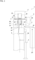
- FIG. 1 depicts an example of side view taken schematically from a right side with respect to a part of the spinning system 1 according to an embodiment of the present invention.
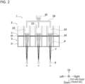
- FIG. 2 depicts an example of front view taken schematically from a forward side with respect to a part of the spinning system 1 shown in FIG. 1 .
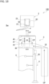
- FIG. 3 depicts an example of schematic view of the spinning system in a state of having caused a cooling unit 3 to move down in the spinning system 1 shown in FIG. 1 .
- the illustrations of a polymer tank 25 and a polymer pipe 26 shown in FIG. 2 are omitted from FIGS. 1 and 3 .
- the yarn Y may be formed as a result of spinning the molten polymer P from a spinneret 24, when the cooling unit 3 is caused to move down, so that the spun molten polymer P is cooled to be solidified through the use of the cooling unit 3 or under other conditions.
- the spinning system 1 is a system for producing a yarn Y made of synthetic fibers.
- the spinning system 1 includes a spinning unit 2, a cooling unit 3, a moving mechanism 5, a blower 6, and a controller 7 (see FIG. 4 to be described later).
- the spinning system 1 includes an oil-agent application unit 8, a take-up unit (not shown), a winder (not shown), and the like. Descriptions of such structures are however omitted here.
- the spinning unit 2 is a melt spinning unit configured to spin molten polymer P as material of a yarn Y.
- the spinning unit 2 includes a spinning beam 21 having a substantially rectangular-solid shape, a plurality of pack housings 22 formed in the spinning beam 21, a plurality of spinning packs 23 (whose number is the same as, e.g., the number of the plurality of pack housings 22) arranged respectively in the plurality of pack housings 22, a polymer tank 25 having polymer stored therein, and a plurality of polymer pipes 26 connecting between their respective spinning packs 23 and the polymer tank 25.
- FIG. 2 For the sake of convenience, three pack housings 22 and three spinning packs 23 are shown in FIG. 2 . However, the invention is not limited to such a configuration. A larger number of pack housings 22 and a larger number of spinning packs 23 (e.g., twelve) may be provided.
- Polymer in the polymer tank 25 is fed through the plurality of polymer pipes 26 to the plurality of spinning packs 23.
- the polymer in the polymer tank 25 and in the polymer pipe 26 is heated by the spinning beam 21 to a predetermined temperature (e.g., 300 oC) to become molten polymer.
- High-temperature heated molten polymer in a liquid state is supplied through the polymer pipe 26 to each spinning pack 23.
- a spinneret 24 is arranged at a lower end portion of each spinning pack 23. That is, the number of the spinnerets 24 is the same as that of the spinning packs 23.
- the spinneret 24 has, e.g., a plurality of nozzles (not shown).
- the spinning pack 23 ejects molten polymer P through the plurality of nozzles of the spinneret 24 (in other words, spins a plurality of yarns Y).
- the molten polymer P ejected through the plurality of nozzles is cooled by the cooling unit 3 to become the plurality of yarns Y having a plurality of filaments.
- one yarn Y is spun from one spinneret 24.
- Each spinneret 24 is not necessarily required to have a plurality of nozzles but may have only one nozzle. In such a case, the yarn Y is produced as monofilament yarn.
- the cooling unit 3 includes a spinning cylinder 31 arranged below the spinning unit 2, a duct 32 connected to the spinning cylinder 31, and a first compressed-air source 37 (see FIG. 4 to be described later) configured to supply cooling air CF to the spinning cylinder 31 through the duct 32.
- a cyclic yarn cooling unit e.g., is used as the cooling unit 3.
- the spinning cylinder 31 is e.g. a hollow box body, and extends in an up-and-down direction so as to surround the molten polymer spun from the spinneret 24 (so as to locate the molten polymer P in a hollow area CE).
- the spinning cylinder 31 includes a flow straightening plate 33 provided therein.
- Air for cooling (the air will be called “cooling air CF") supplied from the first compressed-air source 37 passes through the inside of the duct 32 and is supplied into lower space (space under the flow straightening plate 33) of the spinning cylinder 31.
- the cooling air CF having flowed into the lower space of the spinning cylinder 31 passes through the flow straightening plate 33 to be straightened upward, and then flows into upper space (space over the flow straightening plate 33) of the spinning cylinder 31.
- a plurality of partitioning cylinders 35 is arranged at a position directly below a filter member 36.
- the partitioning cylinder 35 is configured to prevent transmission of the cooling air CF in a radial direction of the partitioning cylinder 35, thereby preventing the cooling air CF from flowing from the lower space of the spinning cylinder 31 directly into the hollow area CE.
- the cooling air CF having flowed into the upper space of the spinning cylinder 31 is straightened in passing through the filter member 36 having, e.g. , a punching filter and a cooling filter, and then flows into the hollow area CE. In such a manner, the cooling air CF is blown on a yarn material from a periphery of the filter member 36, more specifically, from an entire outer perimeter of the filter member 36. As a result, the yarn material is cooled to become the yarn Y.
- a sealing member 40 is provided at a place where the spinning beam 21 and the spinning cylinder 31 are in abutting contact with each other.
- the sealing member 40 can be used for preventing leakage from a surface of the abutting contact between the spinning beam 21 and the spinning cylinder 31.
- the moving mechanism 5 having e.g. an air cylinder (the moving mechanism 5 will be called an air cylinder 5) is configured to cause the cooling unit 3 to move up and down. More specifically, the air cylinder 5 is standing upright on, e.g., a floor surface of a factory.
- the air cylinder 5 has a piston rod 52 extending longitudinally in an up-and-down direction arranged so as to be expandable/contractible in an up-and-down direction.
- the spinning cylinder 31 has a lower end fixed with a wall member 10 extending downward.
- the wall member 10 has a side surface fixed with a tip of the piston rod 52.
- the cooling unit 3 is entirely movable by the actuation of the air cylinder 5 between a first position (see FIG.
- the cooling unit 3 is caused to move up in response to the actuation of the piston rod 52 of the air cylinder 5 in an expanding direction (upward direction in FIG. 1 ) and is caused to move down in response to the actuation of the piston rod 52 in a contracting direction (downward direction in FIG. 1 ).
- the production of the yarn Y is feasible when the cooling unit 3 is at the first position.
- a force acting upward toward the spinning beam 21 is applied to the cooling unit 3 by the air cylinder 5.
- a gap is formed as a working space Sw between the spinning unit 2 (more specifically, the spinning beam 21) and the cooling unit 3 as viewed in an up-and-down direction.
- first position will be called an “upper end”
- second position will be called a “lower end.”
- first position is not limited to the upper end
- second position is not limited to the lower end.
- the blower 6 is a device configured to blow side air SF such that the side air SF flows in a substantially horizontal direction in a working space Sw when the cooling unit 3 is at the lower end.
- blower of air may also be called “release.”
- the blower 6 includes, e.g ., a second compressed-air source 66 (see FIG. 4 to be described later), a plurality of air nozzles 62 through which air (e.g ., compressed air) supplied from the second compressed-air source 66 is releasable as the side air SF, an air pipe 64 connecting the second compressed-air source 66 and each air nozzle 62, and the like.
- the plurality of air nozzles 62 corresponding to the plurality of spinning packs 23, respectively, are arranged side by side in a left-and-right direction.
- the plurality of air nozzles 62 are arranged so as to cause the side air SF released from the air nozzle 62 to flow in one direction from a backward side toward a forward side in a working space Sw formed between the spinning unit 2 and the cooling unit 3 as viewed in an up-and-down direction.
- the reason for causing the side air SF released from the plurality of air nozzles 62 to flow in one direction is to prevent flows of the cooling air CF directed in different directions from interfering with each other.
- the air nozzles 62 may be arranged so as to, e.g., cause the side air SF to flow from a forward side toward a background side.
- the plurality of air nozzles 62 may alternatively be arranged so as to cause the side air SF to flow from a left side toward a right side.
- the plurality of air nozzles 62 are preferably arranged so as to cause the side air SF to flow from a backward side toward a forward side, and vice versa.
- the plurality of air nozzles 62 may be replaced, e.g. , with a single flat nozzle having a greater width than a length in a left-and-right direction from a spinning pack 23 at the left end to a spinning pack 23 at the right end.
- the reason for causing the side air SF released from the air nozzle 62 to flow in a substantially horizontal direction in a working space Sw is to prevent the side air SF released from the air nozzle 62 from going toward the spinneret 24 and toward a place around the spinneret 24.
- the air nozzles 62 are not necessarily required to be arranged so as to cause the compressed air released from the air nozzles 62 to flow as the side air SF in a substantially horizontal direction.
- the air nozzles 62 may be arranged so as to, e.g., cause the compressed air released from the air nozzles 62 to flow diagonally downward. In another case, the air nozzles 62 may be arranged so as to cause the compressed air released from the air nozzles 62 to flow diagonally upward.
- the second compressed-air source 66 for supplying compressed air to the air nozzle 62 and the first compressed-air source 37 for supplying the cooling air CF to the spinning cylinder 31 are provided separately.
- a common compressed-air source may be provided for supplying compressed air to both of the air nozzle 62 and the spinning cylinder 31.
- An air hose e.g., may be used for the connection.
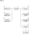
- FIG. 4 depicts an example of function block diagram schematically showing an electrically-connected configuration of the spinning system 1.
- the controller 7 is configured to perform processing relating to operation of the spinning system 1.
- the controller 7 is responsible for controls such as operation and stop of the spinning of molten polymer P from the spinneret 24, actuation and stop of the air cylinder 5, regulation of the flow rate of cooling air CF supplied to the spinning cylinder 31, i.e., into the hollow area CE, and regulation of the flow rate of compressed air released from the air nozzle 62 forming the blower 6.
- temperature decrease suppression means includes the controller 7.
- the controller 7 includes a CPU, ROM, RAM, and the like.
- the controller 7 is connected electrically to units including an operation unit 72 having buttons and the like operable by an operator, an upper end detection sensor 76 for determining that the cooling unit 3 is at the upper end, and a lower end detection sensor 78 for determining that the cooling unit 3 is at the lower end.
- the controller 7 is configured to receive signals from the units including the operation unit 72, the upper end detection sensor 76, and the lower end detection sensor 78.
- the controller 7 is further connected electrically to units including a gear pump 28 capable of causing the spinning of the molten polymer P from the spinneret 24, the first compressed-air source 37, the second compressed-air source 66, and a solenoid 74 configured to actuate the air cylinder.
- a gear pump 28 capable of causing the spinning of the molten polymer P from the spinneret 24, the first compressed-air source 37, the second compressed-air source 66, and a solenoid 74 configured to actuate the air cylinder.
- the controller 7 controls the units including the gear pump 28, the first compressed-air source 37, the second compressed-air source 66, and the solenoid 74.
- the controller 7 controls the solenoid 74 to control actuation of the air cylinder 5.
- the flow rate of the cooling air CF (hereinafter referred to as "air volume") supplied to the spinning cylinder 31 is controlled.
- the flow rate of the side air SF (hereinafter referred to as "air volume” like the cooling air CF) released from the air nozzle 62 is controlled.
- the cooling air CF supplied to the spinning cylinder 31 may be controlled by an automatic valve arranged upstream from the duct 32 instead of operation or stop of the first compressed-air source 37.
- the air volume of the side air SF released from the air nozzle 62 may be controlled by an automatic valve arranged upstream from the air nozzle 62.
- a maintenance step to be undergone by a spinning system will be described. Before description of such a maintenance step according to an embodiment of the present invention conducted for the spinning system 1, a conventional maintenance step will be described by referring to FIGS. 5 to 11 .
- signs given to various structures forming the spinning system 1 according to an embodiment of the present invention are applied as they are to the corresponding structures (including a spinning unit and a cooling unit) forming a conventional spinning system 100.
- the conventional spinning system 100 does not include the above-described blower 6.
- FIG. 5 depicts an example of explanatory view of a maintenance step of the conventional spinning system 100 schematically showing a part thereof in an operational state. While the spinning system 100 is in an operational state, the spinning beam 21 and the cooling unit 3 are in abutting contact with each other. While the spinning system 100 is in operation, the molten polymer P is spun from the spinneret 24 and the cooling air CF is supplied from the first compressed-air source 37 to the spinning cylinder 31 through the duct 32. The cooling air CF supplied to the spinning cylinder 31 flows in a substantially horizontal direction into the hollow area CE to cool the molten polymer P spun from the spinneret 24.
- FIG. 6 depicts an example of explanatory view of a maintenance step of the conventional spinning step schematically showing a part thereof in a state of stopping the spinning of molten polymer 100 in a state where the spinning of the molten polymer P.
- the spinning of the molten polymer P from the spinneret 24 is stopped first, as shown in FIG. 6 .
- the spinning of the molten polymer P is stopped by the controller 7 in response to the operation by, e.g., an operator.
- supply of the cooling air CF by the cooling unit 3 is continued.
- the maintenance corresponds to, e.g. , surface cleaning of the spinneret 24 or exchange of the spinning pack 23.
- FIG. 7 depicts an exemplary view of a maintenance step of the conventional spinning system 100 schematically showing a part thereof in a state of having caused the cooling unit 3 to move down to the lower end with respect to the spinning beam 21.
- the controller 7 actuates the air cylinder 5 in a contracting direction to lower the cooling unit 3 with respect to the spinning beam 21, as shown in FIG. 7 .
- Causing the cooling unit 3 to move down with respect to the spinning beam 21 forms the working space Sw between the spinning unit 2 and the cooling unit 3 as viewed in the up-and-down direction.
- the operator immediately conducts work of covering an upper opening of the spinning cylinder 31 with a cover 42. Covering the upper opening of the spinning cylinder 31 with the cover 42 makes it possible to stop an upward air flow (namely, the cooling air CF) from the upper opening of the spinning cylinder 31.
- FIG. 8 depicts an example of explanatory view of a maintenance step of the conventional spinning system 100 schematically showing a part thereof in a state of allowing the spinning pack 23 to be exchanged.
- FIG. 9 depicts an example of explanatory view of a maintenance step of the conventional spinning system showing a part of the spinning system 100 in a state where the spinning of the molten polymer P is restarted.
- the controller 7 starts (restarts) the spinning of the molten polymer P from the spinneret 24, as shown in FIG. 9 .
- FIG. 10 depicts an example of explanatory view of the maintenance step of the spinning system 100 schematically showing a part thereof in a state of allowing the cover 42 for covering the upper opening of the spinning cylinder 31 to be detached.
- the operator conducts work of detaching the cover 42 covering the upper opening of the spinning cylinder 31.
- FIG. 11 depicts an example of explanatory view of the maintenance step of the spinning system 100 schematically showing a part thereof in a state of allowing the spinning cylinder 31 to have yarn threaded therethrough in yarn threading work.
- the operator conducts yarn threading work of threading the molten polymer P spun from the spinneret 24 (or cooled and solidified yarn Y) through the spinning cylinder 31.
- the controller 7 actuates the air cylinder 5 in an expanding direction to cause the cooling unit 3 to move up so as to make the cooling unit 3 get closer to the spinning beam 21.
- the controller 7 stops actuation of the air cylinder 5, thereby stopping elevation of the cooling unit 3.
- the cooling unit 3 stops at the upper end the spinning beam 21 and the cooling unit 3 abut each other across the sealing member 40. While other preparations for starting production are made in the restoration step, illustrations of these other preparations are omitted.
- the spinning system 100 works normally to be in a state of production.
- the maintenance on the spinning system 100 has conventionally been conducted through the above-described steps.
- FIG. 12 depicts an example of schematic diagram showing a result of circular knit staining evaluation changed with the passage of time from the restoration to an operational state after the maintenance in the conventional maintenance step.
- FIG. 13 depicts a graph showing a result of thermal stress and de-twisting tension on yarn changed with the passage of time from the restoration to an operational state after the maintenance in the conventional maintenance step.
- the result about circular knit staining evaluation is such that, even after passage of about 60 minutes from restoration to a working state, a color is still lighter than a benchmark as a reference (hereinafter called "B. M") so the yarn is not determined to be normal. After passage of about 70 minutes from the restoration to the working state, a color approximate to the B. M is obtained so the yarn is determined to be normal.
- B. M a benchmark as a reference
- both the de-twisting tension and the thermal stress take values approximate to reference values after passage of about 80 to 90 minutes from restoration to a working state.
- B. M as a reference value for the de-twisting tension is about 30.8 [cN], e.g., and B. M as a reference value for the thermal stress is about 83.1 [cN], e.g., the B. M changes in response to the sort of yarn, and the like.
- FIG. 14 depicts a graph showing a surface temperature of the spinneret 24 changed with the passage of time from the starting of maintenance in the conventional maintenance step.
- FIG. 14 when the cooling unit 3 is caused to move down with respect to the spinning beam 21, surface temperature on the spinneret 24 decreases nearly continuously to cause serious decrease of surface temperature on the spinneret 24 at a time when the maintenance is finished.
- surface temperature on the spinneret 24 is recovered gradually.
- a duration of about 2000 s or more is required from start of the elevation of the cooling unit 3.
- maintenance is conducted on the spinning system 1 according to the embodiment of the present invention by a maintenance step described below.
- the following describes the maintenance step conducted on the spinning system 1 according to the embodiment of the present invention.
- the maintenance step according to the present invention will be described by referring to FIGS. 5 , 6 , and 15 to 20 .
- the spinning system 1 according to the embodiment of the present invention largely differs from the conventional spinning system 100 in that the cooling air CF is not supplied to the spinning cylinder 31 in the maintenance step. Since the blower 6 is not in operation in the maintenance step 6, it is to be noted that the spinning system 1 according to the embodiment of the present invention does not necessarily include such a blower 6. The illustration of blower 6 is omitted from FIGS. 15 to 20 .
- the spinning system 1 While the spinning system 1 is working, the lower end of the spinning beam 21 and the upper end of the cooling unit 3 are in abutting contact with each other. While the spinning system 1 is working, the molten polymer P is spun from the spinneret 24 and the cooling air CF is supplied from the first compressed-air source 37 (see FIG. 4 and the same applies to the following cases) to the spinning cylinder 31 through the duct 32.
- the cooling air CF supplied to the spinning cylinder 31 flows in a substantially horizontal direction into the hollow area CE to cool the molten polymer P spun from the spinneret 24.
- the spinning of the molten polymer P from the spinneret 24 is stopped first, as shown in FIG. 6 .
- the spinning of the molten polymer P is stopped by the controller 7 in response to operation by, e.g., an operator.
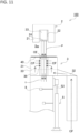
- FIG. 15 depicts an example of view schematically showing a part of the spinning system 1 when the supply of cooling air CF to the spinning cylinder 31 having been stopped.
- the controller 7 Under control by the controller 7, after the spinning of molten polymer P from the spinneret 24 having been stopped, the operation of, e.g., the compressed-air source 37 is stopped, and the supply of cooling air CF to the spinning cylinder 31 is stopped, as shown in, e.g., FIG. 15 .
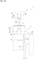
- FIG. 16 depicts an example of view schematically showing a part of the spinning system 1 in a state of having caused the cooling unit 3 to move down to a lower end with respect to the spinning beam 1.
- the controller 7 actuates the air cylinder 5 in a contracting direction to lower the cooling unit 3 with respect to the spinning beam 21, as shown in FIG. 16 .
- Causing the cooling unit 3 to move down with respect to the spinning beam 21 forms the working space Sw between the spinning unit 2 and the cooling unit 3 as viewed in an up-and-down direction.
- the cooling unit 3 is caused to move down with respect to the spinning beam 21, the operator conducts work of covering the upper opening of the spinning cylinder 31 with the cover 42. Covering the upper opening of the spinning cylinder 31 with the cover 42 is not necessarily conducted, however, because the supply of cooling air CF to the spinning cylinder 31 is stopped.
- timing of stopping the spinning of the molten polymer P coincides with a moment before start of causing the cooling unit 3 to move down with respect to the spinning beam 21.
- this is not the only timing but the spinning may be stopped during causing the cooling unit 3 to move down with respect to the spinning beam 21 or after causing the cooling unit 3 to move down to the lower end with respect to the spinning beam 21.
- Timing of stopping supply of the cooling air CF to the spinning cylinder 31 is not limited to a moment after the spinning of the molten polymer P is stopped but may coincide with a moment before the spinning of the molten polymer P is stopped or with a moment substantially simultaneous with stop of the spinning of the molten polymer P.
- the operator After covering the upper opening of the spinning cylinder 31 with the cover 42, which is not necessarily to be conducted, the operator conducts the maintenance including surface cleaning of the spinneret 24 and exchange of the spinning pack 23 in accordance with the purposes. While time required for the maintenance is determined in a manner that depends on the detail of the maintenance, it is generally 10 minutes.
- FIG. 17 depicts an example of view schematically showing a part of the spinning system 1 in a state of restarting the spinning of molten polymer from the spinneret 24.
- the controller 7 starts (restarts) the spinning of the molten polymer P from the spinneret 24, as shown in FIG. 17 .
- FIG. 18 depicts an example of view schematically showing a part of the spinning system 1 in a state of allowing the cover 42 for covering the upper opening of the spinning cylinder 31 to be detached.
- the operator when the spinning of the molten polymer P is restarted, the operator conducts work of detaching the cover 42 covering the upper opening of the spinning cylinder 31. If the upper opening of the spinning cylinder 31 is covered with the cover 42, the operator conducts a work of detaching the cover 42 after the molten polymer P from the spinneret 24 having been started (restarted). At this time, since the supply of cooling air CF to the spinning cylinder 31 is stopped, such a cooling air CF does not flow upward from the upper opening of the spinning cylinder 31.
- Timing of stopping the supply of cooling air CF to the spinning cylinder 31 is as has been described above. If the upper opening of the spinning cylinder 31 is covered with the cover 42, it is only required to stop the supply of cooling air CF to the spinning cylinder 31 at least before detachment of the cover 42. This is because, as long as the upper opening of the spinning cylinder 31 is covered with the cover 42, such a cover 42 can have the function of preventing the cooling air CF from going from the upper opening of the spinning cylinder 31 toward the spinneret 24.
- the step of stopping the supply of cooling air CF to the spinning cylinder 31 corresponds to the temperature decrease suppression step.
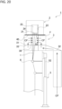
- FIG. 19 depicts an example of view schematically showing a part of the spinning system 1 in a state of allowing the spinning cylinder 31 to have yarn threaded therethrough in yarn threading work.
- the operator conducts yarn threading work of threading the molten polymer P spun from the spinneret 24 (or cooled and solidified yarn Y) through the spinning cylinder 31.
- the cooling air CF is not supplied to the spinning cylinder 31, it is highly likely that the molten polymer P spun from the spinneret 24 will be in a molten state without being cooled and solidified.
- the operator preferably conducts the yarn threading work using a tool such as scissors or the like.
- FIG. 20 depicts an example of view schematically showing a part of the spinning system 1 when having caused the cooling unit 3 to move up to the upper end with respect to the spinning beam 21.
- the controller 7 actuates the air cylinder 5 in an expanding direction to cause the cooling unit 3 to move up so as to be closer to the spinning beam 21, as shown in FIG. 20 .
- the controller 7 stops actuation of the air cylinder 5 to stop causing the cooling unit 3 to move upward.
- the controller 7 restarts operation of the first compressed-air source 37 in response to operation by the operator, e.g., thereby starting the supply of cooling air CF to the spinning cylinder 31, as shown in FIG. 20 .
- Timing of stretching the yarn around the oil-agent application unit 8 is not limited to a moment after having caused the cooling unit 3 to move upward with respect to the spinning beam 21 but may coincide with a moment before causing the cooling unit 3 with respect to the spinning beam 21 is started or with a period when causing the cooling unit 3 to move upward with respect to the spinning beam 21.
- the supply of cooling air CF to the spinning cylinder 31 can be stopped.
- the cooling air CF flowing upward from the spinning cylinder 31 is stopped.
- decrease in temperature at the spinneret 24 and in ambient temperature around the spinneret 24 can be suppressed.
- stopping the supply of cooling air CF is a basis for the descriptions; however, instead of such stopping of the supply, an amount of the supplied cooling air CF to the spinning cylinder 31 may be suppressed.
- the suppressed amount of the cooling air CF supplied to the spinning cylinder 31 results in the suppression of an amount of the cooling air CF supplied from the upper opening of the spinning cylinder 31 to the spinneret 24, and therefore, decrease in temperature at the spinneret 24 and in ambient temperature around the spinneret 24 can be suppressed..
- time for temperature at the spinneret 24 and ambient temperature around the spinneret 24 to recover their original temperatures can be shortened after restoration to a working state to allow reduction in the amount of yarn to be disposed of.
- the maintenance step according to the modification will be described by referring to FIGS. 21 to 27 .
- the state of the spinning system 1 during production or in a working state is the same as that of FIG. 1 , so that a drawing showing the state of the spinning system 1 in a working state is omitted.
- the maintenance step according to the modification largely differs from the maintenance step according to an embodiment of the present invention in that the supply of side air SF to a working space Sw formed in an up-and-down direction between the spinning unit 2 and the cooling unit 3 at least during causing the cooling unit 3 to move downward with respect to the spinning beam 21. It is to be noted that a modified embodiment of the present invention and an embodiment of the present invention are the same as each other in that the cooling air CF is not supplied to the spinning cylinder 31 in the maintenance step.
- the spinning system 1 While the spinning system 1 is in operation, the lower end of the spinning beam 21 and the upper end of the cooling unit 3 are in abutting contact with each other. While the spinning system 1 is in operation, the molten polymer P is spun from the spinneret 24 and the cooling air CF is supplied from the first compressed-air source 37 to the spinning cylinder 31 through the duct 32 (see FIG. 4 ). The cooling air CF supplied to the spinning cylinder 31 flows in a substantially horizontal direction into the hollow area CE to cool the molten polymer P spun from the spinneret 24. While the spinning system 1 is in operation, the side air SF is not released from the air nozzle 62.
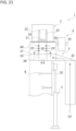
- FIG. 21 depicts an example of view schematically showing a part of the spinning system 1 in a state of stopping the spinning of molten polymer P.
- the spinning of the molten polymer P from the spinneret 24 is stopped first, as shown in FIG. 21 .
- the spinning of the molten polymer P is stopped by the controller 7 in response to operation by, e.g., an operator.
- the blower 6 stops its operation and air is not supplied from the second compressed-air source 66 to the air nozzle 62, so that the side air SF is not released from the air nozzle 62.
- the controller 7 stops operation of the first compressed-air source 37 to stop supply of the cooling air CF to the spinning cylinder 31. Stopping supply of the cooling air CF to the spinning cylinder 31 makes it possible to prevent the cooling air CF from going from the upper opening of the spinning cylinder 31 toward the spinneret 24, thereby preventing serious decrease of temperature at the spinneret 24 and ambient temperature around the spinneret 24.
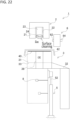
- FIG. 22 depicts an example of view schematically showing a part of the spinning system 1 in a state of having caused the cooling unit 3 to move down to a lower end with respect to the spinning beam 31.
- the controller 7 actuates the air cylinder 5 in a contracting direction to lower the cooling unit 3 with respect to the spinning beam 21, as shown in FIG. 22 .
- Causing the cooling unit 3 to move down with respect to the spinning beam 21 forms the working space Sw between the spinning unit 2 and the cooling unit 3 as viewed in an up-and-down direction.
- the cooling unit 3 is caused to move down with respect to the spinning beam 21, the operator conducts work of covering the upper opening of the spinning cylinder 31 with the cover 42.
- timing of stopping the spinning of the molten polymer P coincides with a moment before start of causing the cooling unit 3 to move down with respect to the spinning beam 21.
- this is not the only timing but the spinning may be stopped during causing the cooling unit 3 with respect to the spinning beam 21 or after causing the cooling unit 3 to move down to the lower end with respect to the spinning beam 21.
- Timing of stopping supply of the cooling air CF to the spinning cylinder 31 is not limited to a moment after the spinning of the molten polymer P is stopped but may coincide with a moment before the spinning of the molten polymer P is stopped or with a moment substantially simultaneous with stop of the spinning of the molten polymer P.
- the operator conducts the maintenance such as surface cleaning of the spinneret 24 or exchange of the spinning pack 23 in response to purpose. While time required for the maintenance is determined in a manner that depends on the detail of the maintenance, it is generally 10 minutes.
- FIG. 23 depicts an example of view schematically showing a part of the spinning system 1 in a state of restarting the spinning of molten polymer P.
- the controller 7 starts (restarts) the spinning of the molten polymer P from the spinneret 24, as shown in FIG. 23 . If the upper opening of the spinning cylinder 31 is covered with the cover 42, the operator conducts work of detaching the cover 42 covering the upper opening of the spinning cylinder 31.
- the foregoing step of stopping supply of the cooling air CF to the spinning cylinder 31 is included in a temperature decrease limiting step. Timing of stopping supply of the cooling air CF to the spinning cylinder 31 is as has been described above. If the upper opening of the spinning cylinder 31 is covered with the cover 42, however, it is only required to stop supply of the cooling air CF to the spinning cylinder 31 at least before detachment of the cover 42. The reason for this is that, while the upper opening of the spinning cylinder 31 is covered with the cover 42, the cover 42 can function to prevent the cooling air CF from going from the upper opening of the spinning cylinder 31 toward the spinneret 24.
- FIG. 24 depicts an example of view schematically showing a part of the spinning system 1 in a state of causing the cooling unit 3 to start operation.
- the controller 7 starts operation of the blower 6.
- the side air SF is released in the working space Sw between the spinning unit 2 and the cooling unit 3 as viewed in an up-and-down direction from the air nozzle 62 in a substantially horizontal direction toward the molten polymer P spun from the spinneret 24.
- a step of releasing the side air SF in the working space Sw from the air nozzle 62 is also included in the temperature decrease limiting step.
- Operation of the blower 6 may be started after detachment of the cover 42 covering the upper opening of the spinning cylinder 31 or before detachment of the cover 42 covering the upper opening of the spinning cylinder 31. At this time, as there is no supply of the cooling air CF to the spinning cylinder 31, serious decrease in temperature at the spinneret 24 and ambient temperature around the spinneret 24 can be suppressed by the cooling air CF going upward from the upper opening of the spinning cylinder 31.
- Timing of starting operation of the blower 6 is not limited to a moment after the spinning of the molten polymer P is restarted but may coincide with a moment before the spinning of the molten polymer P from the spinneret 24 is restarted.
- stopping supply of the cooling air CF to the spinning cylinder 31 makes it possible to limit decrease of temperature at the spinneret 24 and ambient temperature around the spinneret 24.
- stopping supply of the cooling air CF to the spinning cylinder 31 makes it impossible to cool and solidify the molten polymer P spun from the spinneret 24 using the cooling air CF supplied to the spinning cylinder 31.
- Not cooling and solidifying the molten polymer P spun from the spinneret 24 might impose difficulty in conducting yarn threading through the spinning cylinder 31 after the maintenance is finished.
- releasing the side air SF in the working space Sw from the air nozzle 62 toward the molten polymer P spun from the spinneret 24 allows cooling and solidification of the molten polymer P spun from the spinneret 24.
- FIG. 25 depicts an example of view schematically showing a part of the spinning system 1 in a state of allowing the spinning cylinder 31 to have yarn threaded therethrough in yarn threading work.
- the operator when release of the side air SF from the air nozzle 62 is started, the operator conducts yarn threading work of threading the molten polymer P spun from the spinneret 24 (or cooled and solidified yarn Y) through the spinning cylinder 31. At this time, the molten polymer P spun from the spinneret 24 is cooled and solidified by the side air SF released from the air nozzle 62. This allows the operator to conduct the yarn threading work without using a tool.
- FIG. 26 depicts an example of view schematically showing a part of the spinning system 1 in a state of having caused the cooling unit 3 to move up to the upper end with respect to the spinning beam 21.
- the controller 7 actuates the air cylinder 5 in an expanding direction to cause the cooling unit 3 to move up so as to make the cooling unit 3 get closer to the spinning beam 21.
- the controller 7 stops actuation of the air cylinder 5 to stop elevation of the cooling unit 3.
- the controller 7 stops operation of the blower 6 to stop release of the side air SF from the air nozzle 62 so as to finish the air blowing step.
- timing of stopping release of the side air SF from the air nozzle 62 coincides with a moment when the spinning beam 21 and the cooling unit 3 abut each other and elevation of the cooling unit 3 is stopped or a moment after stop of the elevation, as it allows cooling and solidification of the molten polymer P spun from the spinneret 24.
- release of the side air SF from the air nozzle 62 may be stopped before elevation of the cooling unit 3 with respect to the spinning beam 21 is started or during elevation of the cooling unit 3 so as to make the cooling unit 3 get closer to the spinning beam 21.
- the abutting contact between the spinning beam 21 and the cooling unit 3 closes the upper opening of the spinning cylinder 31 to cause the cooling air CF flowing into the hollow area CE to go downward entirely or mostly.
- Timing of stretching the yarn around the oil applicator 8 is not limited to a moment after the cooling unit 3 has been caused to move up with respect to the spinning beam 21 but may coincide with a moment before elevation of the cooling unit 3 with respect to the spinning beam 21 is started or with a period when the cooling unit 3 is being caused to move up with respect to the spinning beam 21. However, this timing preferably coincides with a moment after release of the side air SF from the air nozzle 62 is stopped.
- FIG. 27 depicts an example of view schematically showing a part of the spinning system 1 in a state of being restored to an operational state.
- the controller 7 restarts operation of the first compressed-air source 37 to start supply of the cooling air CF to the spinning cylinder 31.
- Timing of starting supply of the cooling air CF to the spinning cylinder 31 is not limited to a moment when the lower end of the spinning beam 21 and the upper end of the cooling unit 3 abut each other and elevation of the cooling unit 3 is stopped.
- supply of the cooling air CF to the spinning cylinder 31 may be started while the cooling unit 3 is at the lower end.
- Starting supply of the cooling air CF to the spinning cylinder 31 while the cooling unit 3 is at the lower end makes it likely that the cooling air CF will flow from the upper opening of the spinning cylinder 31 toward the spinneret 24.
- the side air SF released from the air nozzle 62 functions as a barrier, it is possible to limit decrease of temperature at the spinneret 24 and ambient temperature around the spinneret 24.
- the foregoing maintenance step according to the modification has been described on the assumption that supply of the cooling air CF to the spinning cylinder 31 is stopped.
- the air volume of the cooling air CF to be supplied to the spinning cylinder 31 may be reduced. Reducing the air volume of the cooling air CF to be supplied to the spinning cylinder 31 reduces the air volume of the cooling air CF to flow from the upper opening of the spinning cylinder 31 toward the spinneret 24, making it possible to limit decrease of temperature at the spinneret 24 and ambient temperature around the spinneret 24.
- this air volume may be reduced at least compared to an air volume during production, namely, before stop of the spinning of the molten polymer P.
- Stopping supply of the cooling air CF to the spinning cylinder 31 or reducing the volume of supply of the cooling air CF during implementation of maintenance on the spinning system 1 might result in the failure to cool and solidify the molten polymer P spun from the spinneret 24 to impose difficulty in the work of threading yarn through the spinning cylinder 31 conducted after the maintenance is finished.
- the side air SF released from the air nozzle 62 flows toward a direction intersecting a yarn path of the molten polymer P spun from the spinneret 24, it is possible to cool and solidify the molten polymer P spun from the spinneret 24.
- FIG. 28 is a schematic view showing result about circular knit staining evaluation that is changed with passage of time from restoration to a working state after implementation of maintenance by the maintenance step according to the present invention.
- FIG. 29 is a graph showing an example of result about thermal stress and de-twisting tension on yarn that are changed with passage of time from restoration to a working state in each of a case where maintenance is conducted by the conventional maintenance step and a case where maintenance is conducted by the maintenance step according to the modification.
- both the de-twisting tension and the thermal stress fulfill more favorable results in the case of implementation of maintenance by the maintenance step of the modification than in the case of implementation of maintenance by the conventional maintenance step.
- FIG. 30 is a graph showing change in surface temperature on the spinneret 24 responsive to passage of time from when maintenance is started by each of the conventional maintenance step, the maintenance step of the present invention, and the maintenance step of the modification.
- (a) shows exemplary change in surface temperature on the spinneret 24 responsive to passage of time from when the maintenance is started by the conventional maintenance step.
- (b) shows exemplary change in surface temperature on the spinneret 24 responsive to passage of time from when the maintenance is started by the maintenance step according to the present invention.
- (c) shows exemplary change in surface temperature on the spinneret 24 responsive to passage of time from when the maintenance is started by the maintenance step according to the modification.
- surface temperature on the spinneret 24 decreases in response to cause the cooling unit 3 to move down with respect to the spinning beam 21 during implementation of each of the conventional maintenance step, the maintenance step of the present invention, and the maintenance step of the modification. After the maintenance is finished and the cooling unit 3 is caused to move up, however, time required for surface temperature on the spinneret 24 to recover its original temperature is shorter in the case of implementation of each of the maintenance step of the present invention and the maintenance step of the modification than in the case of implementation of the conventional maintenance step.
- the cooling air CF is not supplied to the spinning cylinder 31. This results in the absence of the cooling air CF itself to go upward from the upper opening of the spinning cylinder 31 or reduces the air volume of the cooling air CF to go upward from the upper opening of the spinning cylinder 31, thereby allowing limitation on decrease of surface temperature on the spinneret 24.
Landscapes
- Engineering & Computer Science (AREA)
- Mechanical Engineering (AREA)
- Textile Engineering (AREA)
- Spinning Methods And Devices For Manufacturing Artificial Fibers (AREA)
Applications Claiming Priority (1)
| Application Number | Priority Date | Filing Date | Title |
|---|---|---|---|
| JP2022002806 | 2022-01-12 |
Publications (1)
| Publication Number | Publication Date |
|---|---|
| EP4234776A1 true EP4234776A1 (fr) | 2023-08-30 |
Family
ID=84819966
Family Applications (1)
| Application Number | Title | Priority Date | Filing Date |
|---|---|---|---|
| EP23150248.5A Pending EP4234776A1 (fr) | 2022-01-12 | 2023-01-04 | Système de filage et méthode de contrôle d'un système de filage |
Country Status (3)
| Country | Link |
|---|---|
| EP (1) | EP4234776A1 (fr) |
| JP (1) | JP2023102776A (fr) |
| CN (1) | CN116427040A (fr) |
Citations (3)
| Publication number | Priority date | Publication date | Assignee | Title |
|---|---|---|---|---|
| JP2005042227A (ja) | 2003-07-24 | 2005-02-17 | Tmt Machinery Inc | 溶融紡糸装置 |
| JP2006225792A (ja) * | 2005-02-17 | 2006-08-31 | Toray Ind Inc | 合成繊維の溶融紡糸装置およびそれを用いた合成繊維溶融紡糸方法 |
| JP2014145132A (ja) | 2013-01-25 | 2014-08-14 | Tmt Machinery Inc | 紡糸巻取装置 |
Family Cites Families (4)
| Publication number | Priority date | Publication date | Assignee | Title |
|---|---|---|---|---|
| JP2003166114A (ja) * | 2001-11-29 | 2003-06-13 | Teijin Ltd | 溶融紡糸装置 |
| JP2006241611A (ja) * | 2005-03-01 | 2006-09-14 | Teijin Techno Products Ltd | 合成繊維の溶融紡糸装置 |
| CN201339076Y (zh) * | 2009-01-04 | 2009-11-04 | 江苏恒力化纤有限公司 | 纺丝冷却系统的风阀自动控制装置 |
| CN110055607A (zh) * | 2019-04-29 | 2019-07-26 | 吴江精美峰实业有限公司 | 一种纺丝装置 |
-
2022
- 2022-12-21 CN CN202211649337.6A patent/CN116427040A/zh active Pending
-
2023
- 2023-01-04 EP EP23150248.5A patent/EP4234776A1/fr active Pending
- 2023-01-11 JP JP2023002163A patent/JP2023102776A/ja active Pending
Patent Citations (3)
| Publication number | Priority date | Publication date | Assignee | Title |
|---|---|---|---|---|
| JP2005042227A (ja) | 2003-07-24 | 2005-02-17 | Tmt Machinery Inc | 溶融紡糸装置 |
| JP2006225792A (ja) * | 2005-02-17 | 2006-08-31 | Toray Ind Inc | 合成繊維の溶融紡糸装置およびそれを用いた合成繊維溶融紡糸方法 |
| JP2014145132A (ja) | 2013-01-25 | 2014-08-14 | Tmt Machinery Inc | 紡糸巻取装置 |
Also Published As
| Publication number | Publication date |
|---|---|
| CN116427040A (zh) | 2023-07-14 |
| JP2023102776A (ja) | 2023-07-25 |
Similar Documents
| Publication | Publication Date | Title |
|---|---|---|
| US9353463B2 (en) | Spinning point of a spinning machine and method for the operation of the same | |
| US6792744B2 (en) | Spinning device for producing a spun yarn by means of a circulating air flow | |
| US6551545B1 (en) | Method and apparatus for melt spinning a multifilament yarn | |
| JP6094790B2 (ja) | 紡績機及び紡績機における糸の製造を中断する方法 | |
| WO2008116759A2 (fr) | Procédé et dispositif de filature par extrusion, de traitement et d'enroulement d'un fil synthétique | |
| DE102017116893A1 (de) | Fadenführungseinheit, Offenend-Spinnmaschine und Verfahren zum Betreiben einer Spinnstelle | |
| DE19600090A1 (de) | Verfahren und Vorrichtung zur Herstellung von schmelzgesponnenen Monofilen | |
| CN107209127A (zh) | 对丝束的多个熔纺的纤维条子进行质量监控的方法和设备 | |
| EP4234775B1 (fr) | Système de filage et méthode de contrôle d'un système de filage | |
| JPH08506393A (ja) | フィラメントの溶融紡糸方法 | |
| CN106995941B (zh) | 用于制造合成的短纤维的方法和设备 | |
| KR20010049438A (ko) | 용융 방사 공정에서 필라멘트사를 상호혼합, 완화작용 및/또는 열경화하는 장치, 이와 연관되는 처리방법 그리고 이 장치로 제조되는 필라멘트사 | |
| CN120813734A (zh) | 用于供给合成丝线的方法 | |
| JP2021105241A (ja) | 合成糸を溶融紡糸する方法および装置 | |
| JP2007077547A (ja) | 極細ポリアミドマルチフィラメントの製造方法およびポリアミドマルチフィラメント糸の溶融紡糸装置 | |
| JP2023102776A (ja) | 紡糸設備 | |
| EP4471192A2 (fr) | Système d'enroulement de filage et unité d'assistance au filetage de fil | |
| CN114790583A (zh) | 一种tcs涤纶牵伸丝增产设备及方法 | |
| JP3222396B2 (ja) | 多糸条用熱処理装置 | |
| JP2005041673A (ja) | 断糸処理装置 | |
| JP2000027029A (ja) | 高タフネス低収縮ポリエステル繊維の製造方法 | |
| CN215856494U (zh) | 用于形成合成纱线的装置 | |
| JP3598023B2 (ja) | 断糸処理装置 | |
| WO2022211130A1 (fr) | Fibres synthétiques pour coussin de sécurité gonflable, et procédé de fabrication d'étoffe tissée pour coussin de sécurité gonflable utilisant celles-ci | |
| JP4880979B2 (ja) | 多錘延伸装置の断糸処理装置及び断糸処理方法 |
Legal Events
| Date | Code | Title | Description |
|---|---|---|---|
| PUAI | Public reference made under article 153(3) epc to a published international application that has entered the european phase |
Free format text: ORIGINAL CODE: 0009012 |
|
| STAA | Information on the status of an ep patent application or granted ep patent |
Free format text: STATUS: THE APPLICATION HAS BEEN PUBLISHED |
|
| AK | Designated contracting states |
Kind code of ref document: A1 Designated state(s): AL AT BE BG CH CY CZ DE DK EE ES FI FR GB GR HR HU IE IS IT LI LT LU LV MC ME MK MT NL NO PL PT RO RS SE SI SK SM TR |
|
| STAA | Information on the status of an ep patent application or granted ep patent |
Free format text: STATUS: REQUEST FOR EXAMINATION WAS MADE |
|
| 17P | Request for examination filed |
Effective date: 20240229 |
|
| RBV | Designated contracting states (corrected) |
Designated state(s): AL AT BE BG CH CY CZ DE DK EE ES FI FR GB GR HR HU IE IS IT LI LT LU LV MC ME MK MT NL NO PL PT RO RS SE SI SK SM TR |